EP3025821A1 - Procede de soudage pour blindage de l'encoche en forme de z d'aubes en tial - Google Patents
Procede de soudage pour blindage de l'encoche en forme de z d'aubes en tial Download PDFInfo
- Publication number
- EP3025821A1 EP3025821A1 EP15192236.6A EP15192236A EP3025821A1 EP 3025821 A1 EP3025821 A1 EP 3025821A1 EP 15192236 A EP15192236 A EP 15192236A EP 3025821 A1 EP3025821 A1 EP 3025821A1
- Authority
- EP
- European Patent Office
- Prior art keywords
- tank
- molding
- tial
- solder
- armor
- Prior art date
- Legal status (The legal status is an assumption and is not a legal conclusion. Google has not performed a legal analysis and makes no representation as to the accuracy of the status listed.)
- Granted
Links
Images


Classifications
-
- B—PERFORMING OPERATIONS; TRANSPORTING
- B23—MACHINE TOOLS; METAL-WORKING NOT OTHERWISE PROVIDED FOR
- B23K—SOLDERING OR UNSOLDERING; WELDING; CLADDING OR PLATING BY SOLDERING OR WELDING; CUTTING BY APPLYING HEAT LOCALLY, e.g. FLAME CUTTING; WORKING BY LASER BEAM
- B23K1/00—Soldering, e.g. brazing, or unsoldering
- B23K1/0008—Soldering, e.g. brazing, or unsoldering specially adapted for particular articles or work
- B23K1/0018—Brazing of turbine parts
-
- B—PERFORMING OPERATIONS; TRANSPORTING
- B23—MACHINE TOOLS; METAL-WORKING NOT OTHERWISE PROVIDED FOR
- B23K—SOLDERING OR UNSOLDERING; WELDING; CLADDING OR PLATING BY SOLDERING OR WELDING; CUTTING BY APPLYING HEAT LOCALLY, e.g. FLAME CUTTING; WORKING BY LASER BEAM
- B23K11/00—Resistance welding; Severing by resistance heating
- B23K11/002—Resistance welding; Severing by resistance heating specially adapted for particular articles or work
- B23K11/0033—Welding locally a thin plate to a large piece
-
- B—PERFORMING OPERATIONS; TRANSPORTING
- B23—MACHINE TOOLS; METAL-WORKING NOT OTHERWISE PROVIDED FOR
- B23K—SOLDERING OR UNSOLDERING; WELDING; CLADDING OR PLATING BY SOLDERING OR WELDING; CUTTING BY APPLYING HEAT LOCALLY, e.g. FLAME CUTTING; WORKING BY LASER BEAM
- B23K11/00—Resistance welding; Severing by resistance heating
- B23K11/10—Spot welding; Stitch welding
- B23K11/11—Spot welding
-
- B—PERFORMING OPERATIONS; TRANSPORTING
- B23—MACHINE TOOLS; METAL-WORKING NOT OTHERWISE PROVIDED FOR
- B23K—SOLDERING OR UNSOLDERING; WELDING; CLADDING OR PLATING BY SOLDERING OR WELDING; CUTTING BY APPLYING HEAT LOCALLY, e.g. FLAME CUTTING; WORKING BY LASER BEAM
- B23K11/00—Resistance welding; Severing by resistance heating
- B23K11/16—Resistance welding; Severing by resistance heating taking account of the properties of the material to be welded
- B23K11/20—Resistance welding; Severing by resistance heating taking account of the properties of the material to be welded of different metals
-
- B—PERFORMING OPERATIONS; TRANSPORTING
- B23—MACHINE TOOLS; METAL-WORKING NOT OTHERWISE PROVIDED FOR
- B23K—SOLDERING OR UNSOLDERING; WELDING; CLADDING OR PLATING BY SOLDERING OR WELDING; CUTTING BY APPLYING HEAT LOCALLY, e.g. FLAME CUTTING; WORKING BY LASER BEAM
- B23K35/00—Rods, electrodes, materials, or media, for use in soldering, welding, or cutting
- B23K35/02—Rods, electrodes, materials, or media, for use in soldering, welding, or cutting characterised by mechanical features, e.g. shape
- B23K35/0222—Rods, electrodes, materials, or media, for use in soldering, welding, or cutting characterised by mechanical features, e.g. shape for use in soldering or brazing
- B23K35/0233—Sheets or foils
-
- B—PERFORMING OPERATIONS; TRANSPORTING
- B23—MACHINE TOOLS; METAL-WORKING NOT OTHERWISE PROVIDED FOR
- B23K—SOLDERING OR UNSOLDERING; WELDING; CLADDING OR PLATING BY SOLDERING OR WELDING; CUTTING BY APPLYING HEAT LOCALLY, e.g. FLAME CUTTING; WORKING BY LASER BEAM
- B23K35/00—Rods, electrodes, materials, or media, for use in soldering, welding, or cutting
- B23K35/22—Rods, electrodes, materials, or media, for use in soldering, welding, or cutting characterised by the composition or nature of the material
- B23K35/24—Selection of soldering or welding materials proper
- B23K35/30—Selection of soldering or welding materials proper with the principal constituent melting at less than 1550°C
- B23K35/3033—Ni as the principal constituent
-
- B—PERFORMING OPERATIONS; TRANSPORTING
- B23—MACHINE TOOLS; METAL-WORKING NOT OTHERWISE PROVIDED FOR
- B23K—SOLDERING OR UNSOLDERING; WELDING; CLADDING OR PLATING BY SOLDERING OR WELDING; CUTTING BY APPLYING HEAT LOCALLY, e.g. FLAME CUTTING; WORKING BY LASER BEAM
- B23K35/00—Rods, electrodes, materials, or media, for use in soldering, welding, or cutting
- B23K35/22—Rods, electrodes, materials, or media, for use in soldering, welding, or cutting characterised by the composition or nature of the material
- B23K35/24—Selection of soldering or welding materials proper
- B23K35/30—Selection of soldering or welding materials proper with the principal constituent melting at less than 1550°C
- B23K35/3033—Ni as the principal constituent
- B23K35/304—Ni as the principal constituent with Cr as the next major constituent
-
- B—PERFORMING OPERATIONS; TRANSPORTING
- B32—LAYERED PRODUCTS
- B32B—LAYERED PRODUCTS, i.e. PRODUCTS BUILT-UP OF STRATA OF FLAT OR NON-FLAT, e.g. CELLULAR OR HONEYCOMB, FORM
- B32B15/00—Layered products comprising a layer of metal
- B32B15/01—Layered products comprising a layer of metal all layers being exclusively metallic
-
- C—CHEMISTRY; METALLURGY
- C22—METALLURGY; FERROUS OR NON-FERROUS ALLOYS; TREATMENT OF ALLOYS OR NON-FERROUS METALS
- C22C—ALLOYS
- C22C14/00—Alloys based on titanium
-
- C—CHEMISTRY; METALLURGY
- C22—METALLURGY; FERROUS OR NON-FERROUS ALLOYS; TREATMENT OF ALLOYS OR NON-FERROUS METALS
- C22C—ALLOYS
- C22C19/00—Alloys based on nickel or cobalt
- C22C19/03—Alloys based on nickel or cobalt based on nickel
- C22C19/05—Alloys based on nickel or cobalt based on nickel with chromium
-
- C—CHEMISTRY; METALLURGY
- C22—METALLURGY; FERROUS OR NON-FERROUS ALLOYS; TREATMENT OF ALLOYS OR NON-FERROUS METALS
- C22C—ALLOYS
- C22C19/00—Alloys based on nickel or cobalt
- C22C19/03—Alloys based on nickel or cobalt based on nickel
- C22C19/05—Alloys based on nickel or cobalt based on nickel with chromium
- C22C19/058—Alloys based on nickel or cobalt based on nickel with chromium without Mo and W
-
- C—CHEMISTRY; METALLURGY
- C22—METALLURGY; FERROUS OR NON-FERROUS ALLOYS; TREATMENT OF ALLOYS OR NON-FERROUS METALS
- C22C—ALLOYS
- C22C19/00—Alloys based on nickel or cobalt
- C22C19/07—Alloys based on nickel or cobalt based on cobalt
-
- B—PERFORMING OPERATIONS; TRANSPORTING
- B23—MACHINE TOOLS; METAL-WORKING NOT OTHERWISE PROVIDED FOR
- B23K—SOLDERING OR UNSOLDERING; WELDING; CLADDING OR PLATING BY SOLDERING OR WELDING; CUTTING BY APPLYING HEAT LOCALLY, e.g. FLAME CUTTING; WORKING BY LASER BEAM
- B23K2101/00—Articles made by soldering, welding or cutting
- B23K2101/18—Sheet panels
-
- B—PERFORMING OPERATIONS; TRANSPORTING
- B23—MACHINE TOOLS; METAL-WORKING NOT OTHERWISE PROVIDED FOR
- B23K—SOLDERING OR UNSOLDERING; WELDING; CLADDING OR PLATING BY SOLDERING OR WELDING; CUTTING BY APPLYING HEAT LOCALLY, e.g. FLAME CUTTING; WORKING BY LASER BEAM
- B23K2103/00—Materials to be soldered, welded or cut
- B23K2103/08—Non-ferrous metals or alloys
-
- B—PERFORMING OPERATIONS; TRANSPORTING
- B23—MACHINE TOOLS; METAL-WORKING NOT OTHERWISE PROVIDED FOR
- B23K—SOLDERING OR UNSOLDERING; WELDING; CLADDING OR PLATING BY SOLDERING OR WELDING; CUTTING BY APPLYING HEAT LOCALLY, e.g. FLAME CUTTING; WORKING BY LASER BEAM
- B23K2103/00—Materials to be soldered, welded or cut
- B23K2103/08—Non-ferrous metals or alloys
- B23K2103/10—Aluminium or alloys thereof
-
- B—PERFORMING OPERATIONS; TRANSPORTING
- B23—MACHINE TOOLS; METAL-WORKING NOT OTHERWISE PROVIDED FOR
- B23K—SOLDERING OR UNSOLDERING; WELDING; CLADDING OR PLATING BY SOLDERING OR WELDING; CUTTING BY APPLYING HEAT LOCALLY, e.g. FLAME CUTTING; WORKING BY LASER BEAM
- B23K2103/00—Materials to be soldered, welded or cut
- B23K2103/08—Non-ferrous metals or alloys
- B23K2103/14—Titanium or alloys thereof
-
- B—PERFORMING OPERATIONS; TRANSPORTING
- B23—MACHINE TOOLS; METAL-WORKING NOT OTHERWISE PROVIDED FOR
- B23K—SOLDERING OR UNSOLDERING; WELDING; CLADDING OR PLATING BY SOLDERING OR WELDING; CUTTING BY APPLYING HEAT LOCALLY, e.g. FLAME CUTTING; WORKING BY LASER BEAM
- B23K2103/00—Materials to be soldered, welded or cut
- B23K2103/18—Dissimilar materials
-
- C—CHEMISTRY; METALLURGY
- C22—METALLURGY; FERROUS OR NON-FERROUS ALLOYS; TREATMENT OF ALLOYS OR NON-FERROUS METALS
- C22C—ALLOYS
- C22C21/00—Alloys based on aluminium
-
- F—MECHANICAL ENGINEERING; LIGHTING; HEATING; WEAPONS; BLASTING
- F01—MACHINES OR ENGINES IN GENERAL; ENGINE PLANTS IN GENERAL; STEAM ENGINES
- F01D—NON-POSITIVE DISPLACEMENT MACHINES OR ENGINES, e.g. STEAM TURBINES
- F01D5/00—Blades; Blade-carrying members; Heating, heat-insulating, cooling or antivibration means on the blades or the members
- F01D5/12—Blades
- F01D5/22—Blade-to-blade connections, e.g. for damping vibrations
- F01D5/225—Blade-to-blade connections, e.g. for damping vibrations by shrouding
-
- F—MECHANICAL ENGINEERING; LIGHTING; HEATING; WEAPONS; BLASTING
- F05—INDEXING SCHEMES RELATING TO ENGINES OR PUMPS IN VARIOUS SUBCLASSES OF CLASSES F01-F04
- F05D—INDEXING SCHEME FOR ASPECTS RELATING TO NON-POSITIVE-DISPLACEMENT MACHINES OR ENGINES, GAS-TURBINES OR JET-PROPULSION PLANTS
- F05D2230/00—Manufacture
- F05D2230/20—Manufacture essentially without removing material
- F05D2230/23—Manufacture essentially without removing material by permanently joining parts together
- F05D2230/232—Manufacture essentially without removing material by permanently joining parts together by welding
-
- F—MECHANICAL ENGINEERING; LIGHTING; HEATING; WEAPONS; BLASTING
- F05—INDEXING SCHEMES RELATING TO ENGINES OR PUMPS IN VARIOUS SUBCLASSES OF CLASSES F01-F04
- F05D—INDEXING SCHEME FOR ASPECTS RELATING TO NON-POSITIVE-DISPLACEMENT MACHINES OR ENGINES, GAS-TURBINES OR JET-PROPULSION PLANTS
- F05D2230/00—Manufacture
- F05D2230/20—Manufacture essentially without removing material
- F05D2230/23—Manufacture essentially without removing material by permanently joining parts together
- F05D2230/232—Manufacture essentially without removing material by permanently joining parts together by welding
- F05D2230/237—Brazing
-
- F—MECHANICAL ENGINEERING; LIGHTING; HEATING; WEAPONS; BLASTING
- F05—INDEXING SCHEMES RELATING TO ENGINES OR PUMPS IN VARIOUS SUBCLASSES OF CLASSES F01-F04
- F05D—INDEXING SCHEME FOR ASPECTS RELATING TO NON-POSITIVE-DISPLACEMENT MACHINES OR ENGINES, GAS-TURBINES OR JET-PROPULSION PLANTS
- F05D2300/00—Materials; Properties thereof
- F05D2300/10—Metals, alloys or intermetallic compounds
- F05D2300/17—Alloys
- F05D2300/174—Titanium alloys, e.g. TiAl
-
- F—MECHANICAL ENGINEERING; LIGHTING; HEATING; WEAPONS; BLASTING
- F05—INDEXING SCHEMES RELATING TO ENGINES OR PUMPS IN VARIOUS SUBCLASSES OF CLASSES F01-F04
- F05D—INDEXING SCHEME FOR ASPECTS RELATING TO NON-POSITIVE-DISPLACEMENT MACHINES OR ENGINES, GAS-TURBINES OR JET-PROPULSION PLANTS
- F05D2300/00—Materials; Properties thereof
- F05D2300/50—Intrinsic material properties or characteristics
- F05D2300/506—Hardness
Definitions
- the present invention relates to a method of arranging an armor on a TiAl component of a turbomachine, in particular a TiAl engine part, as well as a corresponding component provided with the armor, e.g. an engine component, in particular a blade of a low-pressure turbine.
- Turbomachinery blades for low-pressure turbines of aircraft engines may have shrouds adjacent to each other adjacent to each other.
- the adjacent side surfaces are usually Z-shaped and have contact areas in which the shrouds abut each other directly to contribute to the vibration damping.
- These contact surfaces of the shrouds are usually provided with an armor to keep the mechanical abrasion low.
- Co-Cr alloys in particular so-called Stellite (registered trademark of the company Deloro Stellite), used, for example, by TIG, micro plasma or laser beam welding or by other deposition welding processes are applied.
- Stellite registered trademark of the company Deloro Stellite
- TIG micro plasma or laser beam welding or by other deposition welding processes
- TiAl blades for low-pressure turbines used plasma-sprayed coatings made of Co-Cr alloy T-800 (registered trademark of Deloro Stellite).
- these coatings or armor may not meet the requirements for adhesion properties.
- the armor on a TiAl component with a tank molding which is applied to the TiAl component by means of soldering, wherein the solder used is a nickel-based alloy having the chemical composition 7.5 to 22.5 wt .-% Cr, 0.5 to 7 wt .-% B and the balance nickel and unavoidable impurities.
- solder composition has been found to be advantageous for a stable and reliable solder joint.
- the nickel-base alloy used as a solder may have a chemical composition of 10 to 20% by weight, preferably 12.5 to 17.5% by weight, and most preferably 15% by weight of Cr and 2 to 5% by weight. -%, in particular 3 to 4 wt .-% and most preferably 3.5 wt .-% B, and balance Ni and unavoidable impurities.
- the tank molding can be formed of a metallic material, in particular hard material alloys can be used.
- the material used for the armor is Co - Cr alloys, in particular Co - based alloys with a chromium content of more than 25% by weight and W contents of 4 to 20% by weight. Examples are in particular the Stellite alloys of the company Deloro Stellite.
- the solder can be arranged as a solder foil, wherein, in particular, adhering the solder foil to the shell molding can be realized prior to attaching the armored molding to the TiAl component.
- the adhesion of the solder foil to the tank molding can be realized by spot welding, resistance welding and / or gluing.
- the tank - shaped part can have a special shape, which allows full - surface and secure soldering of the armored molding to the TiAl component.
- the tank molding may have a convex curved surface area, wherein the convex curved surface area may be inserted into a concavely curved surface area of a pocket of the TiAl component to provide complementary configuration of the convex surface portion of the tank molding and the concave surface of the receiving pocket of the TiAl component to realize a particularly stable and secure connection of the molded part to the TiAl component via a solder layer.
- both TiAl components in the area of the application site and the armored molding can be surface treated, in particular by blasting with particles, preferably SiC particles, so that a cleaning and Compaction of the surfaces takes place.
- a surface treatment of only one of the surfaces can also be carried out.
- the shell molding can be fixed during soldering, in particular with a rod that holds the tank molding on the TiAl component.
- the rod can be a ceramic rod, a glass rod or a graphite rod, with a graphite rod in particular being advantageous because, owing to the good thermal conductivity of the graphite, a uniform temperature adjustment over the armored molding during soldering is possible.
- the soldering process itself can be monitored by means of a pyrometer and a thermal imaging camera, so that with the monitoring result, a targeted control and / or regulation of the soldering process is possible.
- the pyrometer and / or thermal imager monitoring results can provide suitable temperature control and / or control.
- the soldering can be carried out at a soldering temperature of 1050 ° C to 1130 ° C, preferably at 1090 ° C, wherein the holding time at the soldering temperature in the range of 10 s to 300 s can be.
- a component which is formed from a TiAl material that is, a material in which the largest components are an alloy composition Ti and Al are included.
- they are TiAl alloys that form intermetallic phases in the form of titanium aluminides, such as gamma-TiAl or ⁇ 2Ti3Al.
- the Fig. 1 shows a plan view of a shroud 1 of a blade, as it can be used for example in a low-pressure turbine of an aircraft engine.
- the moving blade and the shroud 1 consist of a high-strength and high-temperature-resistant titanium aluminide alloy, ie an alloy which is essentially formed of intermetallic phases, such as ⁇ 2 -Ti 3 Al or y-TiAl, and is generally referred to herein as TiAl alloy becomes.
- the shroud 1 has a substantially plate-like shape with two spaced apart, extending in the direction of rotation, outer sealing lips or sealing webs 4, 5 and two Z-shaped side surfaces 2 and 3, which bear against adjacent blades or shrouds.
- the Z-shaped side surfaces 2, 3 each have a contact surface 6, 7 for mutual contact with adjacent blades or shrouds for vibration damping. To reduce the abrasion on the contact surfaces 6, 7, these are each provided with an armor 8, 9.
- the armours 8, 9, which are provided on the contact surfaces 6, 7 of the shroud 1, are formed from shell moldings 10 (see Fig. 2 and 3) soldered to the shroud 1.
- a solder foil 11 is used for soldering, which is attached to the tank - molded part 10.
- the adhesion of the solder foil can be done by spot welding and in particular resistance spot welding or gluing.
- the adhesive with which the brazing foil 11 can be attached to the armor molding 10 should be selected such that the adhesive evaporates rapidly even at a temperature below the brazing temperature in vacuum, so that the adhesive has no negative effects on the production of the brazing layer and not incorporated in the solder layer.
- the thickness of the solder foil 11 can be selected in the range from 25 ⁇ m to 100 ⁇ m, preferably 50 ⁇ m.
- the solder foil can, as in FIG. 2 Shown with protrusion to the tank molding 10, with a protrusion of 0.1 mm to 1 mm with respect to the width B of the tank molding 10 (see FIG. 3b ) or with a protrusion of 0.1 mm to 2 mm in the longitudinal direction L (see FIG. 3a ).
- the supernatant of the solder foil 11 ensures that complete moistening of the tank molding 10 and the bearing surface on the cover strip 1 takes place, so that a full-surface solder layer can be formed.
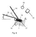
- the tank-shaped part 10 has essentially the basic shape of a parallelepiped, in particular a cuboid, wherein two, extending in the width direction and diagonally opposite edges are rounded in and convex curved surface regions 12, 13 form. With such a shape, the shell moldings can be placed particularly well in pockets 16, which can be formed in the region of the so-called Z-notch (Z-groove), as in FIG FIG. 4 is shown.
- the pockets 16 may have an at least partially complementary shape to the shape of the tank moldings 10, in particular a concave curvature 17, which corresponds to the convex curvature 12, 13 of the tank molding 10 at the rounded edge, so that the tank molding with a continuous extending surface is arranged on the shroud 1.
- convex curvature which is accommodated in the concave curvature of the shroud 1, opposite convex curvature 12 of the tank molding 10 allows on the one hand better contact with the shroud of the adjacent blade and on the other hand the universal use of a corresponding tank - shaped part 10 both on the one as well as on the other side corresponding Z - grooves of the shroud.
- the shell molded parts 10 are defined over a corresponding length L, a height H and a width B, which are adapted to the corresponding dimensions of the associated pockets 16 in the shroud 1 of the TiAl rotor blades ,
- the correspondingly shaped pockets 16 of the shroud 1 as well as the tank - shaped parts 10 can be soldered, in particular before the soldering foil 11 is attached to the tank - shaped part 10, as in FIG. 2 shown surface-treated, so that a cleaning and preparation of the respective surface for the subsequent soldering process is given.
- a suitable surface pretreatment consists, for example, in blasting the surfaces with particles, for example SiC particles, in order to remove corresponding contamination and / or to densify the surface.
- the tank molding 10 After attaching the brazing foil 11 to the tank molding 10 and arranging the thus prepared tank molding 10 in a pocket 16 of the shroud 1, the tank molding 10 is fixed by means of a rod 14, so that during the soldering process a defined position of the tank -Form part can be ensured and a full-surface connection of the tank - molded part 10 can be secured to the shroud 1.
- the rod 14 may be made of glass, ceramic or graphite and in particular be formed of isostatically pressed graphite.
- Graphite or isostatically pressed graphite is preferred because this material has a high thermal conductivity, so that over the rod 14 during the soldering process heat can be dissipated and thus a uniform temperature distribution over the TiAl - base material of the shroud 1 and the Tank - molded part 10 can be achieved.
- a reliable fixation of the tank molding 10 in the pocket 16 is ensured by arranging the TiAl component during the soldering process so inclined that the armor molding 10 and in particular the convex surface thereof through the Gravity in the pocket 16 and the concave bulge 17 is pressed.
- the inclination angle ⁇ may be selected, for example, in the range of 5 ° to 30 ° relative to the horizontal.
- the soldering takes place by means of the solder foil 11 and an inductive heating of the solder foil 11 or the solder, as shown in FIG. 4 is illustrated by the coil 15.
- the soldering process takes place in a vacuum chamber (not shown) or under a suitable protective gas atmosphere.
- the soldering temperature is between 1050 ° C and 1130 ° C, preferably around 1090 ° C.
- the soldering time or the holding time of the soldering temperature is between 10 seconds and 300 seconds, preferably in the range of 30 seconds.
- the cooling to a temperature in the range of 700 ° C to 900 ° C is carried out at a cooling rate in the range of 5 K / min to 100 K / min.
- a pyrometer 18 is provided which influences the operation of the induction coil 15 via a control and / or regulating device, not shown, so that the soldering temperature and the cooling rates are in the desired ranges.
- the melting of the solder foil 11 can be monitored with a thermal imaging camera 19 in order to ensure a secure and stable connection of the tank molding 10 and the cover tape 1 by a controlled and defined soldering process.
- a post-processing of the shroud 1 with the tank - shaped part 10 is usually no longer necessary.
- the proposed method can be used not only to produce armor of a Z-notch on shrouds of TiAl blades, which has previously been described in detail, but also to repair such components.
- the inventive method can of course be used with other components or for the manufacture and repair of other armor and / or other components.
Landscapes
- Engineering & Computer Science (AREA)
- Mechanical Engineering (AREA)
- Chemical & Material Sciences (AREA)
- Materials Engineering (AREA)
- Metallurgy (AREA)
- Organic Chemistry (AREA)
- Turbine Rotor Nozzle Sealing (AREA)
- General Engineering & Computer Science (AREA)
- Ceramic Products (AREA)
- Architecture (AREA)
- Composite Materials (AREA)
Applications Claiming Priority (1)
| Application Number | Priority Date | Filing Date | Title |
|---|---|---|---|
| DE102014224156.1A DE102014224156B4 (de) | 2014-11-26 | 2014-11-26 | Lötverfahren zur Panzerung der Z-Notch von TIAL-Schaufeln und Bauteil einer Strömungsmaschine mit einer solchen Panzerung |
Publications (2)
| Publication Number | Publication Date |
|---|---|
| EP3025821A1 true EP3025821A1 (fr) | 2016-06-01 |
| EP3025821B1 EP3025821B1 (fr) | 2019-06-19 |
Family
ID=54540823
Family Applications (1)
| Application Number | Title | Priority Date | Filing Date |
|---|---|---|---|
| EP15192236.6A Not-in-force EP3025821B1 (fr) | 2014-11-26 | 2015-10-30 | Procede de soudage pour blindage de l'encoche en forme de z d'aubes en tial |
Country Status (4)
| Country | Link |
|---|---|
| US (1) | US20160146020A1 (fr) |
| EP (1) | EP3025821B1 (fr) |
| DE (1) | DE102014224156B4 (fr) |
| ES (1) | ES2738350T3 (fr) |
Families Citing this family (3)
| Publication number | Priority date | Publication date | Assignee | Title |
|---|---|---|---|---|
| US10421147B2 (en) * | 2015-11-17 | 2019-09-24 | General Electric Company | Fixture and method for resistance welding of a pad to a surface |
| US10598030B2 (en) * | 2017-01-10 | 2020-03-24 | General Electric Company | Assembly, treated article, and process of treating a turbine component |
| DE102018202726A1 (de) | 2018-02-22 | 2019-08-22 | MTU Aero Engines AG | Bauteil, insbesondere Laufschaufel, für eine Strömungsmaschine mit einer Panzerungsdoppelschicht |
Citations (5)
| Publication number | Priority date | Publication date | Assignee | Title |
|---|---|---|---|---|
| US5890274A (en) * | 1996-03-14 | 1999-04-06 | Societe Nationale D'etude Et De Construction De Moteurs D'aviation "Snecma", | Method of producing a coating layer on a localized area of a superalloy component |
| EP0999009A1 (fr) * | 1998-11-02 | 2000-05-10 | General Electric Company | Procédé pour appliquer des matériaux résistants à l'usure aux aubes de turbine et aubes de turbine obtenues |
| WO2011009430A1 (fr) | 2009-07-22 | 2011-01-27 | Mtu Aero Engines Gmbh | Procédé de revêtement d'une aube de turbine |
| DE102011086524A1 (de) * | 2011-11-17 | 2013-05-23 | Mtu Aero Engines Gmbh | Panzerung von Dichtfins von TiAl-Schaufeln durch induktives Auftragslöten von Hartstoffpartikeln |
| DE102011087158A1 (de) * | 2011-11-25 | 2013-05-29 | Mtu Aero Engines Gmbh | Verfahren zur Panzerung der Z-Notch von TiAl-Schaufeln |
Family Cites Families (2)
| Publication number | Priority date | Publication date | Assignee | Title |
|---|---|---|---|---|
| US8771439B2 (en) * | 2009-04-01 | 2014-07-08 | Ut-Battelle, Llc | Titanium aluminide intermetallic alloys with improved wear resistance |
| FR2963261B1 (fr) * | 2010-07-29 | 2012-09-07 | Turbomeca | Procede de brasage par induction de pieces de forme complexe, et poste de brasage simple et multiple de mise en ?uvre |
-
2014
- 2014-11-26 DE DE102014224156.1A patent/DE102014224156B4/de not_active Expired - Fee Related
-
2015
- 2015-10-30 EP EP15192236.6A patent/EP3025821B1/fr not_active Not-in-force
- 2015-10-30 ES ES15192236T patent/ES2738350T3/es active Active
- 2015-11-23 US US14/948,526 patent/US20160146020A1/en not_active Abandoned
Patent Citations (5)
| Publication number | Priority date | Publication date | Assignee | Title |
|---|---|---|---|---|
| US5890274A (en) * | 1996-03-14 | 1999-04-06 | Societe Nationale D'etude Et De Construction De Moteurs D'aviation "Snecma", | Method of producing a coating layer on a localized area of a superalloy component |
| EP0999009A1 (fr) * | 1998-11-02 | 2000-05-10 | General Electric Company | Procédé pour appliquer des matériaux résistants à l'usure aux aubes de turbine et aubes de turbine obtenues |
| WO2011009430A1 (fr) | 2009-07-22 | 2011-01-27 | Mtu Aero Engines Gmbh | Procédé de revêtement d'une aube de turbine |
| DE102011086524A1 (de) * | 2011-11-17 | 2013-05-23 | Mtu Aero Engines Gmbh | Panzerung von Dichtfins von TiAl-Schaufeln durch induktives Auftragslöten von Hartstoffpartikeln |
| DE102011087158A1 (de) * | 2011-11-25 | 2013-05-29 | Mtu Aero Engines Gmbh | Verfahren zur Panzerung der Z-Notch von TiAl-Schaufeln |
Also Published As
| Publication number | Publication date |
|---|---|
| ES2738350T3 (es) | 2020-01-22 |
| DE102014224156A1 (de) | 2016-06-02 |
| EP3025821B1 (fr) | 2019-06-19 |
| DE102014224156B4 (de) | 2024-05-23 |
| US20160146020A1 (en) | 2016-05-26 |
Similar Documents
| Publication | Publication Date | Title |
|---|---|---|
| EP2590773B1 (fr) | Procédé et dispositif de dépot de couches de matériau sur une pièce en tial | |
| DE69702416T2 (de) | Nickel-Basis-Hartlotmaterial | |
| EP2780552B1 (fr) | Blindage d'ailettes d'étanchéité d'aubes en tial par dépôt de particules de matériau dur par brasage par induction | |
| EP3153269B1 (fr) | Réparation de surfaces d'objets usées | |
| WO2006069941A1 (fr) | Composant comprenant un canal incorpore, en particulier composant a gaz chauds d'une turbomachine | |
| DE102015205316A1 (de) | Verfahren zum Erzeugen eines Bauteiles aus einer Superlegierung mit einem pulverbettbasierten additiven Herstellungsverfahren und Bauteil aus einer Superlegierung | |
| EP3238868A1 (fr) | Procédé de fabrication d'une lame de rotor pour un moteur de fluide | |
| WO2010121597A2 (fr) | Procédé de production d'un blindage d'un bout d'aube et aubes ainsi produites et turbines à gaz | |
| CH709882A2 (de) | Verfahren zum Zusammenfügen von Hochtemperaturmaterialien und damit hergestellte Artikel. | |
| EP3025821B1 (fr) | Procede de soudage pour blindage de l'encoche en forme de z d'aubes en tial | |
| DE2208070A1 (de) | Plasma-flammgespritzte titancarbidwerkzeugstahl-ueberzuege auf metallsubstraten, die so gebildeten verbundwerkstoffe und verfahren zu deren herstellung | |
| DE102013205956A1 (de) | Blisk mit Titanaluminid-Schaufeln und Verfahren zur Herstellung | |
| EP2808488B1 (fr) | Aube en TiAl dotée d'une modification de surface | |
| EP2371977B1 (fr) | Alliage de cobalt et son procédé de fabrication | |
| DE102019210430A1 (de) | Elektronenstrahlschweißen von Nickelbasis-Superlegierungen und Vorrichtung | |
| DE602004001369T2 (de) | Verfahren zum verbesserten Schweisseindringen durch Bildung einer Oxidschicht und daraus resultiertes Produkt. | |
| DE3212768A1 (de) | Schweissverfahren | |
| DE102016224386A1 (de) | Verfahren zum herstellen einer schaufel für eine strömungsmaschine | |
| DE102014209847A1 (de) | Verfahren zur Reparatur eines Schaufelblattes | |
| EP2840166B1 (fr) | Couche de protection contre l'usure inter-métallique pour matières premières en titane | |
| DE102018212480A1 (de) | Additives Herstellungsverfahren mit selektivem Bestrahlen und gleichzeitigem Auftragen sowie Wärmebehandlung | |
| EP2485863A1 (fr) | Procédé de soudage par fusion d'une pièce monocristalline et d'une pièce polycristalline, et rotor | |
| DE102008036450A1 (de) | Labyrinth-Dichtungssteg-Reparaturverfahren für Gasturbinen | |
| EP3493931A1 (fr) | Procédé de fabrication d'une structure de conduit et constituants | |
| DE102012002285B4 (de) | Verfahren zum Herstellen eines Turbinenrotors |
Legal Events
| Date | Code | Title | Description |
|---|---|---|---|
| PUAI | Public reference made under article 153(3) epc to a published international application that has entered the european phase |
Free format text: ORIGINAL CODE: 0009012 |
|
| AK | Designated contracting states |
Kind code of ref document: A1 Designated state(s): AL AT BE BG CH CY CZ DE DK EE ES FI FR GB GR HR HU IE IS IT LI LT LU LV MC MK MT NL NO PL PT RO RS SE SI SK SM TR |
|
| AX | Request for extension of the european patent |
Extension state: BA ME |
|
| STAA | Information on the status of an ep patent application or granted ep patent |
Free format text: STATUS: REQUEST FOR EXAMINATION WAS MADE |
|
| 17P | Request for examination filed |
Effective date: 20161117 |
|
| RBV | Designated contracting states (corrected) |
Designated state(s): AL AT BE BG CH CY CZ DE DK EE ES FI FR GB GR HR HU IE IS IT LI LT LU LV MC MK MT NL NO PL PT RO RS SE SI SK SM TR |
|
| REG | Reference to a national code |
Ref country code: DE Ref legal event code: R079 Ref document number: 502015009367 Country of ref document: DE Free format text: PREVIOUS MAIN CLASS: B23K0035300000 Ipc: B23K0011000000 |
|
| GRAP | Despatch of communication of intention to grant a patent |
Free format text: ORIGINAL CODE: EPIDOSNIGR1 |
|
| STAA | Information on the status of an ep patent application or granted ep patent |
Free format text: STATUS: GRANT OF PATENT IS INTENDED |
|
| RIC1 | Information provided on ipc code assigned before grant |
Ipc: B23K 35/02 20060101ALI20190211BHEP Ipc: B23K 11/00 20060101AFI20190211BHEP Ipc: B23K 1/00 20060101ALI20190211BHEP Ipc: B23K 103/10 20060101ALI20190211BHEP Ipc: B32B 15/01 20060101ALI20190211BHEP Ipc: C22C 14/00 20060101ALI20190211BHEP Ipc: B23K 103/18 20060101ALI20190211BHEP Ipc: F01D 5/22 20060101ALI20190211BHEP Ipc: B23K 11/20 20060101ALI20190211BHEP Ipc: B23K 103/14 20060101ALI20190211BHEP Ipc: B23K 11/11 20060101ALI20190211BHEP Ipc: C22C 21/00 20060101ALI20190211BHEP Ipc: C22C 19/05 20060101ALI20190211BHEP Ipc: B23K 35/30 20060101ALI20190211BHEP Ipc: B23K 101/18 20060101ALI20190211BHEP Ipc: C22C 19/07 20060101ALI20190211BHEP Ipc: B23K 103/08 20060101ALI20190211BHEP |
|
| INTG | Intention to grant announced |
Effective date: 20190301 |
|
| GRAS | Grant fee paid |
Free format text: ORIGINAL CODE: EPIDOSNIGR3 |
|
| GRAA | (expected) grant |
Free format text: ORIGINAL CODE: 0009210 |
|
| STAA | Information on the status of an ep patent application or granted ep patent |
Free format text: STATUS: THE PATENT HAS BEEN GRANTED |
|
| AK | Designated contracting states |
Kind code of ref document: B1 Designated state(s): AL AT BE BG CH CY CZ DE DK EE ES FI FR GB GR HR HU IE IS IT LI LT LU LV MC MK MT NL NO PL PT RO RS SE SI SK SM TR |
|
| REG | Reference to a national code |
Ref country code: GB Ref legal event code: FG4D Free format text: NOT ENGLISH |
|
| REG | Reference to a national code |
Ref country code: CH Ref legal event code: EP |
|
| REG | Reference to a national code |
Ref country code: IE Ref legal event code: FG4D Free format text: LANGUAGE OF EP DOCUMENT: GERMAN |
|
| REG | Reference to a national code |
Ref country code: DE Ref legal event code: R096 Ref document number: 502015009367 Country of ref document: DE |
|
| REG | Reference to a national code |
Ref country code: AT Ref legal event code: REF Ref document number: 1144862 Country of ref document: AT Kind code of ref document: T Effective date: 20190715 |
|
| REG | Reference to a national code |
Ref country code: NL Ref legal event code: MP Effective date: 20190619 |
|
| PG25 | Lapsed in a contracting state [announced via postgrant information from national office to epo] |
Ref country code: AL Free format text: LAPSE BECAUSE OF FAILURE TO SUBMIT A TRANSLATION OF THE DESCRIPTION OR TO PAY THE FEE WITHIN THE PRESCRIBED TIME-LIMIT Effective date: 20190619 Ref country code: LT Free format text: LAPSE BECAUSE OF FAILURE TO SUBMIT A TRANSLATION OF THE DESCRIPTION OR TO PAY THE FEE WITHIN THE PRESCRIBED TIME-LIMIT Effective date: 20190619 Ref country code: NO Free format text: LAPSE BECAUSE OF FAILURE TO SUBMIT A TRANSLATION OF THE DESCRIPTION OR TO PAY THE FEE WITHIN THE PRESCRIBED TIME-LIMIT Effective date: 20190919 Ref country code: HR Free format text: LAPSE BECAUSE OF FAILURE TO SUBMIT A TRANSLATION OF THE DESCRIPTION OR TO PAY THE FEE WITHIN THE PRESCRIBED TIME-LIMIT Effective date: 20190619 Ref country code: SE Free format text: LAPSE BECAUSE OF FAILURE TO SUBMIT A TRANSLATION OF THE DESCRIPTION OR TO PAY THE FEE WITHIN THE PRESCRIBED TIME-LIMIT Effective date: 20190619 Ref country code: FI Free format text: LAPSE BECAUSE OF FAILURE TO SUBMIT A TRANSLATION OF THE DESCRIPTION OR TO PAY THE FEE WITHIN THE PRESCRIBED TIME-LIMIT Effective date: 20190619 |
|
| REG | Reference to a national code |
Ref country code: LT Ref legal event code: MG4D |
|
| PG25 | Lapsed in a contracting state [announced via postgrant information from national office to epo] |
Ref country code: RS Free format text: LAPSE BECAUSE OF FAILURE TO SUBMIT A TRANSLATION OF THE DESCRIPTION OR TO PAY THE FEE WITHIN THE PRESCRIBED TIME-LIMIT Effective date: 20190619 Ref country code: LV Free format text: LAPSE BECAUSE OF FAILURE TO SUBMIT A TRANSLATION OF THE DESCRIPTION OR TO PAY THE FEE WITHIN THE PRESCRIBED TIME-LIMIT Effective date: 20190619 Ref country code: BG Free format text: LAPSE BECAUSE OF FAILURE TO SUBMIT A TRANSLATION OF THE DESCRIPTION OR TO PAY THE FEE WITHIN THE PRESCRIBED TIME-LIMIT Effective date: 20190919 Ref country code: GR Free format text: LAPSE BECAUSE OF FAILURE TO SUBMIT A TRANSLATION OF THE DESCRIPTION OR TO PAY THE FEE WITHIN THE PRESCRIBED TIME-LIMIT Effective date: 20190920 |
|
| REG | Reference to a national code |
Ref country code: ES Ref legal event code: FG2A Ref document number: 2738350 Country of ref document: ES Kind code of ref document: T3 Effective date: 20200122 |
|
| PG25 | Lapsed in a contracting state [announced via postgrant information from national office to epo] |
Ref country code: NL Free format text: LAPSE BECAUSE OF FAILURE TO SUBMIT A TRANSLATION OF THE DESCRIPTION OR TO PAY THE FEE WITHIN THE PRESCRIBED TIME-LIMIT Effective date: 20190619 Ref country code: SK Free format text: LAPSE BECAUSE OF FAILURE TO SUBMIT A TRANSLATION OF THE DESCRIPTION OR TO PAY THE FEE WITHIN THE PRESCRIBED TIME-LIMIT Effective date: 20190619 Ref country code: RO Free format text: LAPSE BECAUSE OF FAILURE TO SUBMIT A TRANSLATION OF THE DESCRIPTION OR TO PAY THE FEE WITHIN THE PRESCRIBED TIME-LIMIT Effective date: 20190619 Ref country code: CZ Free format text: LAPSE BECAUSE OF FAILURE TO SUBMIT A TRANSLATION OF THE DESCRIPTION OR TO PAY THE FEE WITHIN THE PRESCRIBED TIME-LIMIT Effective date: 20190619 Ref country code: EE Free format text: LAPSE BECAUSE OF FAILURE TO SUBMIT A TRANSLATION OF THE DESCRIPTION OR TO PAY THE FEE WITHIN THE PRESCRIBED TIME-LIMIT Effective date: 20190619 Ref country code: PT Free format text: LAPSE BECAUSE OF FAILURE TO SUBMIT A TRANSLATION OF THE DESCRIPTION OR TO PAY THE FEE WITHIN THE PRESCRIBED TIME-LIMIT Effective date: 20191021 |
|
| PG25 | Lapsed in a contracting state [announced via postgrant information from national office to epo] |
Ref country code: IT Free format text: LAPSE BECAUSE OF FAILURE TO SUBMIT A TRANSLATION OF THE DESCRIPTION OR TO PAY THE FEE WITHIN THE PRESCRIBED TIME-LIMIT Effective date: 20190619 Ref country code: SM Free format text: LAPSE BECAUSE OF FAILURE TO SUBMIT A TRANSLATION OF THE DESCRIPTION OR TO PAY THE FEE WITHIN THE PRESCRIBED TIME-LIMIT Effective date: 20190619 Ref country code: IS Free format text: LAPSE BECAUSE OF FAILURE TO SUBMIT A TRANSLATION OF THE DESCRIPTION OR TO PAY THE FEE WITHIN THE PRESCRIBED TIME-LIMIT Effective date: 20191019 |
|
| PG25 | Lapsed in a contracting state [announced via postgrant information from national office to epo] |
Ref country code: TR Free format text: LAPSE BECAUSE OF FAILURE TO SUBMIT A TRANSLATION OF THE DESCRIPTION OR TO PAY THE FEE WITHIN THE PRESCRIBED TIME-LIMIT Effective date: 20190619 |
|
| PG25 | Lapsed in a contracting state [announced via postgrant information from national office to epo] |
Ref country code: PL Free format text: LAPSE BECAUSE OF FAILURE TO SUBMIT A TRANSLATION OF THE DESCRIPTION OR TO PAY THE FEE WITHIN THE PRESCRIBED TIME-LIMIT Effective date: 20190619 Ref country code: DK Free format text: LAPSE BECAUSE OF FAILURE TO SUBMIT A TRANSLATION OF THE DESCRIPTION OR TO PAY THE FEE WITHIN THE PRESCRIBED TIME-LIMIT Effective date: 20190619 |
|
| PG25 | Lapsed in a contracting state [announced via postgrant information from national office to epo] |
Ref country code: MC Free format text: LAPSE BECAUSE OF FAILURE TO SUBMIT A TRANSLATION OF THE DESCRIPTION OR TO PAY THE FEE WITHIN THE PRESCRIBED TIME-LIMIT Effective date: 20190619 Ref country code: IS Free format text: LAPSE BECAUSE OF FAILURE TO SUBMIT A TRANSLATION OF THE DESCRIPTION OR TO PAY THE FEE WITHIN THE PRESCRIBED TIME-LIMIT Effective date: 20200224 |
|
| REG | Reference to a national code |
Ref country code: CH Ref legal event code: PL |
|
| REG | Reference to a national code |
Ref country code: DE Ref legal event code: R097 Ref document number: 502015009367 Country of ref document: DE |
|
| PLBE | No opposition filed within time limit |
Free format text: ORIGINAL CODE: 0009261 |
|
| STAA | Information on the status of an ep patent application or granted ep patent |
Free format text: STATUS: NO OPPOSITION FILED WITHIN TIME LIMIT |
|
| PG2D | Information on lapse in contracting state deleted |
Ref country code: IS |
|
| PG25 | Lapsed in a contracting state [announced via postgrant information from national office to epo] |
Ref country code: LI Free format text: LAPSE BECAUSE OF NON-PAYMENT OF DUE FEES Effective date: 20191031 Ref country code: LU Free format text: LAPSE BECAUSE OF NON-PAYMENT OF DUE FEES Effective date: 20191030 Ref country code: CH Free format text: LAPSE BECAUSE OF NON-PAYMENT OF DUE FEES Effective date: 20191031 |
|
| 26N | No opposition filed |
Effective date: 20200603 |
|
| REG | Reference to a national code |
Ref country code: BE Ref legal event code: MM Effective date: 20191031 |
|
| PG25 | Lapsed in a contracting state [announced via postgrant information from national office to epo] |
Ref country code: SI Free format text: LAPSE BECAUSE OF FAILURE TO SUBMIT A TRANSLATION OF THE DESCRIPTION OR TO PAY THE FEE WITHIN THE PRESCRIBED TIME-LIMIT Effective date: 20190619 Ref country code: BE Free format text: LAPSE BECAUSE OF NON-PAYMENT OF DUE FEES Effective date: 20191031 |
|
| PG25 | Lapsed in a contracting state [announced via postgrant information from national office to epo] |
Ref country code: IE Free format text: LAPSE BECAUSE OF NON-PAYMENT OF DUE FEES Effective date: 20191030 |
|
| PG25 | Lapsed in a contracting state [announced via postgrant information from national office to epo] |
Ref country code: CY Free format text: LAPSE BECAUSE OF FAILURE TO SUBMIT A TRANSLATION OF THE DESCRIPTION OR TO PAY THE FEE WITHIN THE PRESCRIBED TIME-LIMIT Effective date: 20190619 |
|
| PG25 | Lapsed in a contracting state [announced via postgrant information from national office to epo] |
Ref country code: MT Free format text: LAPSE BECAUSE OF FAILURE TO SUBMIT A TRANSLATION OF THE DESCRIPTION OR TO PAY THE FEE WITHIN THE PRESCRIBED TIME-LIMIT Effective date: 20190619 Ref country code: HU Free format text: LAPSE BECAUSE OF FAILURE TO SUBMIT A TRANSLATION OF THE DESCRIPTION OR TO PAY THE FEE WITHIN THE PRESCRIBED TIME-LIMIT; INVALID AB INITIO Effective date: 20151030 |
|
| REG | Reference to a national code |
Ref country code: AT Ref legal event code: MM01 Ref document number: 1144862 Country of ref document: AT Kind code of ref document: T Effective date: 20201030 |
|
| PG25 | Lapsed in a contracting state [announced via postgrant information from national office to epo] |
Ref country code: AT Free format text: LAPSE BECAUSE OF NON-PAYMENT OF DUE FEES Effective date: 20201030 |
|
| PG25 | Lapsed in a contracting state [announced via postgrant information from national office to epo] |
Ref country code: MK Free format text: LAPSE BECAUSE OF FAILURE TO SUBMIT A TRANSLATION OF THE DESCRIPTION OR TO PAY THE FEE WITHIN THE PRESCRIBED TIME-LIMIT Effective date: 20190619 |
|
| PGFP | Annual fee paid to national office [announced via postgrant information from national office to epo] |
Ref country code: GB Payment date: 20231025 Year of fee payment: 9 |
|
| PGFP | Annual fee paid to national office [announced via postgrant information from national office to epo] |
Ref country code: ES Payment date: 20231117 Year of fee payment: 9 |
|
| PGFP | Annual fee paid to national office [announced via postgrant information from national office to epo] |
Ref country code: FR Payment date: 20231023 Year of fee payment: 9 Ref country code: DE Payment date: 20231018 Year of fee payment: 9 |
|
| REG | Reference to a national code |
Ref country code: DE Ref legal event code: R119 Ref document number: 502015009367 Country of ref document: DE |
|
| GBPC | Gb: european patent ceased through non-payment of renewal fee |
Effective date: 20241030 |
|
| PG25 | Lapsed in a contracting state [announced via postgrant information from national office to epo] |
Ref country code: DE Free format text: LAPSE BECAUSE OF NON-PAYMENT OF DUE FEES Effective date: 20250501 |
|
| PG25 | Lapsed in a contracting state [announced via postgrant information from national office to epo] |
Ref country code: GB Free format text: LAPSE BECAUSE OF NON-PAYMENT OF DUE FEES Effective date: 20241030 |
|
| PG25 | Lapsed in a contracting state [announced via postgrant information from national office to epo] |
Ref country code: FR Free format text: LAPSE BECAUSE OF NON-PAYMENT OF DUE FEES Effective date: 20241031 |
|
| REG | Reference to a national code |
Ref country code: ES Ref legal event code: FD2A Effective date: 20251205 |
|
| PG25 | Lapsed in a contracting state [announced via postgrant information from national office to epo] |
Ref country code: ES Free format text: LAPSE BECAUSE OF NON-PAYMENT OF DUE FEES Effective date: 20241031 |