EP3025827A1 - Coffret d'outil dote de plusieurs stations de charge - Google Patents
Coffret d'outil dote de plusieurs stations de charge Download PDFInfo
- Publication number
- EP3025827A1 EP3025827A1 EP15187824.6A EP15187824A EP3025827A1 EP 3025827 A1 EP3025827 A1 EP 3025827A1 EP 15187824 A EP15187824 A EP 15187824A EP 3025827 A1 EP3025827 A1 EP 3025827A1
- Authority
- EP
- European Patent Office
- Prior art keywords
- charging
- accumulator
- tool
- accumulators
- charging station
- Prior art date
- Legal status (The legal status is an assumption and is not a legal conclusion. Google has not performed a legal analysis and makes no representation as to the accuracy of the status listed.)
- Withdrawn
Links
- 230000000295 complement effect Effects 0.000 claims description 4
- 238000011156 evaluation Methods 0.000 description 5
- 238000003780 insertion Methods 0.000 description 3
- 230000037431 insertion Effects 0.000 description 3
- 238000006243 chemical reaction Methods 0.000 description 2
- 238000012360 testing method Methods 0.000 description 2
- 230000006978 adaptation Effects 0.000 description 1
- 230000015572 biosynthetic process Effects 0.000 description 1
- 238000013461 design Methods 0.000 description 1
- 238000001514 detection method Methods 0.000 description 1
- 238000005755 formation reaction Methods 0.000 description 1
- 238000007689 inspection Methods 0.000 description 1
- 238000012423 maintenance Methods 0.000 description 1
- 230000009466 transformation Effects 0.000 description 1
- 230000000007 visual effect Effects 0.000 description 1
Images

Classifications
-
- B—PERFORMING OPERATIONS; TRANSPORTING
- B25—HAND TOOLS; PORTABLE POWER-DRIVEN TOOLS; MANIPULATORS
- B25H—WORKSHOP EQUIPMENT, e.g. FOR MARKING-OUT WORK; STORAGE MEANS FOR WORKSHOPS
- B25H3/00—Storage means or arrangements for workshops facilitating access to, or handling of, work tools or instruments
- B25H3/02—Boxes
Definitions
- the invention relates to a tool case with a plurality of charging stations for batteries and / or accumulator-operated tools, wherein a supply of the charging station is provided with electric current.
- Such tool cases are, for example, from the DE 10 2012 111 328 A1 and the DE 10 2012 111 321 A1 known.
- the state of the art is also on the DE 10 2009 027 571 A1 to refer.
- the invention has for its object to provide a tool case with several charging stations for accumulators and / or accumulator-operated tools, which allows an advantageous charging of the accumulators and / or accumulator-operated tools.
- the charging stations can be supplied with different charging voltages.
- the charging stations can also be supplied with different charging currents.
- accumulators and / or accumulator-operated tools can be charged at the same time, of which at least two accumulators and / or accumulator-operated tools require different charging voltages and possibly different charging currents. It is also important that with only one charging device, which preferably the mains connection and preferably a transformation of the mains voltage into one or more charging voltages or optionally one or more charging currents brings a plurality of possibly different accumulators and / or accumulator-powered tools can be loaded.
- the charging stations can be supplied with different charging voltages at the same time and that accumulators and / or accumulator-operated tools can be charged at the same time as the charging stations, which accumulators and / or accumulator-operated tools are supplied with different charging voltages. It is then possible, several accumulators and / or several accumulator-powered tools that require different charging voltages, simultaneously, supplied by the same charging device to load in charging stations that are adaptable to the respective required charging voltage and possibly the respective required charging current or are supplied accordingly ,
- an accumulator and / or an accumulator-operated tool can be assigned only to a charging station and configured with the proviso that charging of the accumulator and / or of the accumulator-operated tool takes place or can be carried out exclusively in the charging station assigned to the tool.
- a charging station it is essential that the accumulator or Akkumulator Seaene tool is used in terms of the required charging voltage and, where appropriate, the required charging current in exactly the charging station or is connected to this conductive, suitable with respect to the charging voltage and optionally the charging current is.
- a charging station can be designed as a charging tray into which a substantial part of the accumulator and / or of the accumulator-operated tool can be inserted.
- an overvoltage protection for example in the form of a conventional fuse, can be provided.
- the surge protection can be integrated into the charging device or each charging station can be assigned a separate surge protection.
- accumulator or the accumulator-operated tool In order to ensure that the accumulator or the accumulator-operated tool is only used in or connected to a charging station which is suitably designed with respect to the charging voltage and / or the charging current, means may be provided which avoid that a rechargeable battery or an accumulator-operated tool is connected to or inserted in a mismatched charging station.
- the accumulators and / or the accumulator-operated tools may each have a coding element and the charging station associated with an accumulator and / or an accumulator-operated tool have a coding element that is complementary to the coding element, with loading of the accumulator or of the accumulator-operated tool preferably taking place only when the coding element cooperates with the corresponding coding element.
- the means or the coding element and / or the complementary coding element can, for example, in a first, possibly leading, contacting, which makes a query regarding the appropriate charging voltage or the appropriate charging current, generated acoustic, visual and / or haptic (for example vibrate) signal.
- This signal may originate from the accumulator or the accumulator-operated tool and / or the charging station.
- a shutter member may also be effective to prevent further insertion and actual contact with respect to the charging voltage or the charging current with respect to the rechargeable battery or accumulator-operated tool. It is possible that the charging station reads out a tool-side and / or accumulator-side and preferably accumulator-specific RFID chip and the charging station Charging voltage is adjustable in dependence on the information stored in the RFID chip information in the charging station.
- An evaluation unit required for testing whether an accumulator or an accumulator-operated tool is to be inserted into or connected to a non-matching charging device may be part of the charging device.
- the evaluation unit can in particular make it possible to detect and evaluate measurable currents or voltages when inserting or first contacting the accumulator or accumulator-operated tool with the charging device.
- the evaluation unit can for this purpose have a microprocessor.
- the means which are to ensure the appropriate charging voltage or, where appropriate, the appropriate charging current, from a in a charging connection an individual shape adjustment between the accumulator or the Akkumumulator congressenen tool and the charging station requiring formations on the accumulator or the Akkumumulator congressenen tool on the one hand and the charging station on the other hand. It may be form-coded fits that allow only in accordance with a charge required for conductive connection between the charging station and the accumulator or the accumulator-powered tool. As a result, a purely mechanical test can be carried out so that an evaluation unit as described above can be dispensed with.
- the signals mentioned can be deliverable independently of the specific configuration of the means in one or more of the mentioned embodiments.
- the loading device which supplies the charging stations, can be arranged in the tool box itself.
- the charger can be outside the
- Tool case such as by an electrical connector connectable to the tool box, be provided.
- the loading device can be provided so that it can be connected to the tool case.
- An optionally provided outside the tool case charging device then has a power plug for the power supply of the charging device.
- the power supply takes place by means of a 12V or 24V DC power source, which is preferably provided in cars or trucks.
- the power supply via a 100V to 250V power grid preferably with AC voltage.
- the tool case is preferably modular. This means in particular that one, several or all charging stations can be provided interchangeable.
- the charging stations are exchangeable without tools. They may be provided so interchangeable that while they are conveniently interchangeable as part of a maintenance, but are not interchangeable for a user. This can be achieved by providing certain screws, which require, for example, a special tool for the solution, for exchangeable mounting of at least one charging station in the tool box.
- a charging contact or a unit with several or all related charging contacts in the charging station be provided interchangeable.
- the interchangeability of a charging device or a charging contact and a unit with several or all relevant charging contacts in the charging station can be provided to make a conversion in terms of a different, possibly higher charging voltage and / or charging current.
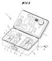
- a tool case 1 Shown and described is a tool case 1 with a plurality of charging stations 2, 3, 4, 5, for accumulator-powered tools 6, 7, 8 and 9.
- the tool case 1 has in further detail a suitcase base 10 and a case lid 11.
- the tools 6, 7, 8, 9 are preferably inextricably linked with their respective accumulator for a user.
- a charging station 2, 3, 4, 5 may be designed to receive only the accumulator.
- the charging stations 2, 3, 4, 5 are formed in the case base 10 in the embodiment.
- a loading device 13 is arranged, which is also received in the suitcase bottom part 10 accordingly.
- the loading device 13 can also be arranged, for example, in the case lid 11-preferably visible. It can also be arranged visible in the case bottom part 10 on the upper side.
- the different charging stations 2, 3, 4 and 5 can be supplied with a charging voltage and a charging current.
- the charging device 13 can be connected via a power cable 14 and a power plug 15, which may be provided on the power cable 14 end, with an electrical network.
- all charging stations 2, 3, 4, 5 can be supplied with a specific charging voltage and a specific charging current.
- means may be provided for establishing a charging connection between an accumulator-operated tool 6 , 7, 8, 9 and a charging station 2, 3, 4, 5, which are not intended for each other to avoid.
- These means may initially consist of an individualized adaptation (not shown in detail) between the accumulator-operated tool 6, 7, 8, 9, specifically its area, which can be inserted into the charging station 2, 3, 4, 5, and the charging station 2, 3 4, 5 on the other hand. So it is a form coding possible. In the simplest case, this can, for example, go from a smallest contact distance to a maximum contact distance.
- An accumulator-operated tool 6, 7, 8, 9 with a larger contact distance can not be inserted into a charging station 2, 3, 4, 5 with a smaller contact distance.
- An accumulator-operated tool 6, 7, 8, 9 with a smaller contact distance can then, for example, although possibly in a charging station 2, 3, 4, 5 are used with a larger contact distance, since this is not an electrical contact to the example. two required contacts can come, so no charging is possible.
- the said means may consist in a detection of resistors and / or currents, which may preferably result in the course of insertion into a charging station 2, 3, 4, 5 (precontact).
- the detected resistances and / or currents are evaluated by an evaluation unit as described above, wherein a charging station 2, 3, 4, 5 is deactivated in case of incorrect insertion of an accumulator-operated tool 6, 7, 8, 9.
- the modular structure may mean that a charging station 2, 3, 4, 5 and / or a charging contact formed in the charging station 2, 3, 4, 5 or a unit of a plurality of charging contacts in a charging station 2, 3, 4, 5 in FIG easily exchangeable.
- the interchangeability may require a tool operation, such as with a screwdriver. But it can also be given with respect to a latch, so that an appropriate replacement can be carried out without tools if necessary.
- the charging device 13 may be provided interchangeable, such as for conversion to a charging station 2, 3, 4, 5 with a different charging voltage and / or another charging current.
Landscapes
- Engineering & Computer Science (AREA)
- Mechanical Engineering (AREA)
- Charge And Discharge Circuits For Batteries Or The Like (AREA)
Applications Claiming Priority (1)
| Application Number | Priority Date | Filing Date | Title |
|---|---|---|---|
| DE102014117239.6A DE102014117239A1 (de) | 2014-11-25 | 2014-11-25 | Werkzeugkoffer mit mehreren Ladestationen |
Publications (1)
| Publication Number | Publication Date |
|---|---|
| EP3025827A1 true EP3025827A1 (fr) | 2016-06-01 |
Family
ID=54256573
Family Applications (1)
| Application Number | Title | Priority Date | Filing Date |
|---|---|---|---|
| EP15187824.6A Withdrawn EP3025827A1 (fr) | 2014-11-25 | 2015-10-01 | Coffret d'outil dote de plusieurs stations de charge |
Country Status (2)
| Country | Link |
|---|---|
| EP (1) | EP3025827A1 (fr) |
| DE (1) | DE102014117239A1 (fr) |
Families Citing this family (2)
| Publication number | Priority date | Publication date | Assignee | Title |
|---|---|---|---|---|
| DE102017210128A1 (de) * | 2017-06-16 | 2018-12-20 | Robert Bosch Gmbh | Stromversorgungsvorrichtung für eine Handwerkzeugmaschine |
| WO2022155867A1 (fr) * | 2021-01-22 | 2022-07-28 | 何春纬 | Mallette de transport médical longue distance |
Citations (5)
| Publication number | Priority date | Publication date | Assignee | Title |
|---|---|---|---|---|
| DE102007057552A1 (de) * | 2007-10-10 | 2009-04-23 | Manfred Gehmeyr | Ladestation und Verfahren zum Laden von Akkumulatoren sowie Ladesystem mit einer Ladestation und mit wenigstens einem Akkumulator |
| US20110006729A1 (en) * | 2009-07-09 | 2011-01-13 | Wolf Matthias | Rechargeable battery charging case |
| DE102010029557A1 (de) * | 2010-06-01 | 2011-12-01 | Robert Bosch Gmbh | Akkuladekoffer |
| DE102012111328A1 (de) | 2012-11-23 | 2014-05-28 | Vorwerk & Co. Interholding Gmbh | Koffer für akkumulatorbetriebene Werkzeuge |
| DE102012111321A1 (de) | 2012-11-23 | 2014-05-28 | Vorwerk & Co. Interholding Gmbh | Trageinrichtung mit Halterungsaufnahmen |
-
2014
- 2014-11-25 DE DE102014117239.6A patent/DE102014117239A1/de not_active Withdrawn
-
2015
- 2015-10-01 EP EP15187824.6A patent/EP3025827A1/fr not_active Withdrawn
Patent Citations (6)
| Publication number | Priority date | Publication date | Assignee | Title |
|---|---|---|---|---|
| DE102007057552A1 (de) * | 2007-10-10 | 2009-04-23 | Manfred Gehmeyr | Ladestation und Verfahren zum Laden von Akkumulatoren sowie Ladesystem mit einer Ladestation und mit wenigstens einem Akkumulator |
| US20110006729A1 (en) * | 2009-07-09 | 2011-01-13 | Wolf Matthias | Rechargeable battery charging case |
| DE102009027571A1 (de) | 2009-07-09 | 2011-05-12 | Robert Bosch Gmbh | Akkuladekoffer |
| DE102010029557A1 (de) * | 2010-06-01 | 2011-12-01 | Robert Bosch Gmbh | Akkuladekoffer |
| DE102012111328A1 (de) | 2012-11-23 | 2014-05-28 | Vorwerk & Co. Interholding Gmbh | Koffer für akkumulatorbetriebene Werkzeuge |
| DE102012111321A1 (de) | 2012-11-23 | 2014-05-28 | Vorwerk & Co. Interholding Gmbh | Trageinrichtung mit Halterungsaufnahmen |
Also Published As
| Publication number | Publication date |
|---|---|
| DE102014117239A1 (de) | 2016-05-25 |
Similar Documents
| Publication | Publication Date | Title |
|---|---|---|
| DE3934799C2 (fr) | ||
| DE4036374A1 (de) | Ladeeinrichtung fuer wiederaufladbare batterien | |
| DE102005029020A1 (de) | Tragbare Werkzeugaufbewahrungsvorrichtung mit Energieversorgungseinheit | |
| EP2841294B1 (fr) | Procédé pour préparation d'alimentation d'énergie d'un véhicule | |
| DE102009027571A1 (de) | Akkuladekoffer | |
| DE4036373A1 (de) | Ladeeinrichtung fuer wiederaufladbare batterien | |
| EP3336954A1 (fr) | Batterie configurable | |
| DE202012100613U1 (de) | Prüfstecker für Ladestationen | |
| DE102012111321A1 (de) | Trageinrichtung mit Halterungsaufnahmen | |
| DE112014007057T5 (de) | Energiespeichersystem basiert auf Batteriepacks | |
| DE102017212496B4 (de) | Hochvoltakkuvorrichtung und Verfahren zum Betreiben einer Hochvoltakkuvorrichtung | |
| WO2019110308A1 (fr) | Station de charge pour charger électriquement des accumulateurs d'énergie de véhicules automobiles | |
| EP3025827A1 (fr) | Coffret d'outil dote de plusieurs stations de charge | |
| DE102011000969A1 (de) | Verfahren und Vorrichtung zur Montage von Akkumulatorbatterien | |
| DE102010026608A1 (de) | Energieversorgungs-Modul und Anschlußvorrichtung hierfür | |
| EP3503313B1 (fr) | Adaptateur de batteries multiples permettant d'établir une connexion électrique entre au moins deux batteries de traction d'un côté et une unité de transmission d'une bicyclette électrique d'un autre côté | |
| DE202013002556U1 (de) | Trolley | |
| EP3031584A1 (fr) | Récipient destiné à ranger au moins un appareil entrainé par batterie | |
| WO2014029582A1 (fr) | Véhicule pour fonctionnement sur réseau ferroviaire et sur batterie | |
| DE202016100637U1 (de) | Batterieanordnung und Batteriehalter zur Verwendung in einem Elektrowerkzeug und Batterieladegerät | |
| DE202017001477U1 (de) | Transportkoffer mit einer Ladevorrichtung für zumindest ein akkubetriebenes Elektrogerät | |
| DE3641908A1 (de) | Selbsteinschaltende, wiederaufladbare pannen-sicherheits-warnblinkleuchte | |
| DE102015204295A1 (de) | Sicherungshalter | |
| DE102021119943A1 (de) | Ladestation | |
| DE102013105025A1 (de) | Verfahren und Steuerungseinrichtung zum Laden eines elektrischen Energiespeichers eines Kraftfahrzeugs sowie Kraftfahrzeug |
Legal Events
| Date | Code | Title | Description |
|---|---|---|---|
| PUAI | Public reference made under article 153(3) epc to a published international application that has entered the european phase |
Free format text: ORIGINAL CODE: 0009012 |
|
| AK | Designated contracting states |
Kind code of ref document: A1 Designated state(s): AL AT BE BG CH CY CZ DE DK EE ES FI FR GB GR HR HU IE IS IT LI LT LU LV MC MK MT NL NO PL PT RO RS SE SI SK SM TR |
|
| AX | Request for extension of the european patent |
Extension state: BA ME |
|
| 17P | Request for examination filed |
Effective date: 20160916 |
|
| RBV | Designated contracting states (corrected) |
Designated state(s): AL AT BE BG CH CY CZ DE DK EE ES FI FR GB GR HR HU IE IS IT LI LT LU LV MC MK MT NL NO PL PT RO RS SE SI SK SM TR |
|
| GRAP | Despatch of communication of intention to grant a patent |
Free format text: ORIGINAL CODE: EPIDOSNIGR1 |
|
| RIC1 | Information provided on ipc code assigned before grant |
Ipc: B25H 3/02 20060101AFI20190628BHEP |
|
| INTG | Intention to grant announced |
Effective date: 20190805 |
|
| STAA | Information on the status of an ep patent application or granted ep patent |
Free format text: STATUS: THE APPLICATION IS DEEMED TO BE WITHDRAWN |
|
| 18D | Application deemed to be withdrawn |
Effective date: 20200701 |