EP3025945B1 - Garde-boue avant de véhicule à selle - Google Patents
Garde-boue avant de véhicule à selle Download PDFInfo
- Publication number
- EP3025945B1 EP3025945B1 EP15195855.0A EP15195855A EP3025945B1 EP 3025945 B1 EP3025945 B1 EP 3025945B1 EP 15195855 A EP15195855 A EP 15195855A EP 3025945 B1 EP3025945 B1 EP 3025945B1
- Authority
- EP
- European Patent Office
- Prior art keywords
- parts
- front fender
- saddle
- fork tubes
- rearwardly
- Prior art date
- Legal status (The legal status is an assumption and is not a legal conclusion. Google has not performed a legal analysis and makes no representation as to the accuracy of the status listed.)
- Active
Links
Images



Classifications
-
- B—PERFORMING OPERATIONS; TRANSPORTING
- B62—LAND VEHICLES FOR TRAVELLING OTHERWISE THAN ON RAILS
- B62J—CYCLE SADDLES OR SEATS; AUXILIARY DEVICES OR ACCESSORIES SPECIALLY ADAPTED TO CYCLES AND NOT OTHERWISE PROVIDED FOR, e.g. ARTICLE CARRIERS OR CYCLE PROTECTORS
- B62J15/00—Mud-guards for wheels
-
- B—PERFORMING OPERATIONS; TRANSPORTING
- B62—LAND VEHICLES FOR TRAVELLING OTHERWISE THAN ON RAILS
- B62J—CYCLE SADDLES OR SEATS; AUXILIARY DEVICES OR ACCESSORIES SPECIALLY ADAPTED TO CYCLES AND NOT OTHERWISE PROVIDED FOR, e.g. ARTICLE CARRIERS OR CYCLE PROTECTORS
- B62J17/00—Weather guards for riders; Fairings or stream-lining parts not otherwise provided for
- B62J17/02—Weather guards for riders; Fairings or stream-lining parts not otherwise provided for shielding only the rider's front
-
- B—PERFORMING OPERATIONS; TRANSPORTING
- B62—LAND VEHICLES FOR TRAVELLING OTHERWISE THAN ON RAILS
- B62J—CYCLE SADDLES OR SEATS; AUXILIARY DEVICES OR ACCESSORIES SPECIALLY ADAPTED TO CYCLES AND NOT OTHERWISE PROVIDED FOR, e.g. ARTICLE CARRIERS OR CYCLE PROTECTORS
- B62J23/00—Other protectors specially adapted for cycles
-
- B—PERFORMING OPERATIONS; TRANSPORTING
- B62—LAND VEHICLES FOR TRAVELLING OTHERWISE THAN ON RAILS
- B62K—CYCLES; CYCLE FRAMES; CYCLE STEERING DEVICES; RIDER-OPERATED TERMINAL CONTROLS SPECIALLY ADAPTED FOR CYCLES; CYCLE AXLE SUSPENSIONS; CYCLE SIDECARS, FORECARS, OR THE LIKE
- B62K11/00—Motorcycles, engine-assisted cycles or motor scooters with one or two wheels
- B62K11/02—Frames
- B62K11/04—Frames characterised by the engine being between front and rear wheels
-
- B—PERFORMING OPERATIONS; TRANSPORTING
- B62—LAND VEHICLES FOR TRAVELLING OTHERWISE THAN ON RAILS
- B62K—CYCLES; CYCLE FRAMES; CYCLE STEERING DEVICES; RIDER-OPERATED TERMINAL CONTROLS SPECIALLY ADAPTED FOR CYCLES; CYCLE AXLE SUSPENSIONS; CYCLE SIDECARS, FORECARS, OR THE LIKE
- B62K25/00—Axle suspensions
- B62K25/04—Axle suspensions for mounting axles resiliently on cycle frame or fork
- B62K25/06—Axle suspensions for mounting axles resiliently on cycle frame or fork with telescopic fork, e.g. including auxiliary rocking arms
- B62K25/08—Axle suspensions for mounting axles resiliently on cycle frame or fork with telescopic fork, e.g. including auxiliary rocking arms for front wheel
-
- B—PERFORMING OPERATIONS; TRANSPORTING
- B62—LAND VEHICLES FOR TRAVELLING OTHERWISE THAN ON RAILS
- B62M—RIDER PROPULSION OF WHEELED VEHICLES OR SLEDGES; POWERED PROPULSION OF SLEDGES OR SINGLE-TRACK CYCLES; TRANSMISSIONS SPECIALLY ADAPTED FOR SUCH VEHICLES
- B62M7/00—Motorcycles characterised by position of motor or engine
- B62M7/02—Motorcycles characterised by position of motor or engine with engine between front and rear wheels
- B62M7/04—Motorcycles characterised by position of motor or engine with engine between front and rear wheels below the frame
Definitions
- the present invention relates to a saddle-type vehicle with a front fender that guides a relative wind (that is, airflow relative to the vehicle, arising from the movement of the vehicle) to an engine and radiators.
- a relative wind flowing on the upper surface of the front fender tends to flow upward along a headlight and a front cover (front number plate and so forth), and it is important to guide the relative wind to the engine side and the side of the radiators disposed in front of the engine for cooling.
- a structure is known in which a wind guide path, which allows the upper surface side and lower surface side of a front fender to communicate with each other, is made in order to cause a relative wind flowing on the upper surface of the front fender to efficiently impinge on an engine (see, for example, Japanese Patent Laid-Open No. 2006-15930 ).
- a saddle-type vehicle said vehicle including a vehicle body frame including a head pipe, a main frame extending downwardly and rearwardly from the head pipe, and a down-frame extending downwardly and rearwardly from the head pipe, an engine disposed below the main frame, a steering shaft pivotally supported by the head pipe so as to be steerable, a bottom bridge attached to a lower end part of the steering shaft, a pair of left and right fork tubes that are attached to left and right end parts of the bottom bridge and support a front wheel at lower end parts of the fork tubes such that the front wheel can move generally vertically, and a front fender fixed to the bottom bridge or the fork tubes, wherein the front fender includes a front fender main body part having a substantially inverted U-shaped section, open downwardly, and step parts extending from left and right end parts of the front fender main body part toward both lateral sides, at least at a part of the front fender to the front of
- the step parts are formed to extend from a front part of the front fender upwardly and rearwardly along an upper edge contour line in side view of the front fender and then extend downwardly and rearwardly at a part near the front side of the fork tubes.
- Radiators are each provided at a position that is offset to at least one of left and right of the down-frame and is lower than the bottom bridge, and extensions of rear end parts of the step parts pass through radiator cores of the radiators in side view.
- a relative wind that impinges on left and right parts of the front fender can be made to flow with orientations along the step parts downwardly and rearwardly.
- the relative wind can be made to impinge on the engine disposed to the rear of the step parts, and cooling of the engine can be promoted. Because this is achieved through the shape of the front fender, there are no increases in the weight and the number of parts of the front fender.
- the relative wind can be effectively guided to the radiator cores and the performance of cooling the radiators can be improved.
- a height difference between the front fender main body part and the step parts gradually becomes larger in a direction from the front side of the front fender toward a rear side. This facilitates the flowing of the relative wind along the step parts.
- an angle ⁇ of rear end parts of the step parts with respect to the fork tubes is set to a substantially right angle or a smaller angle.
- the relative wind is made to flow from the rear end parts of the step parts toward the vehicle body rear side at substantially a right angle or a smaller angle to the fork tubes. This can facilitate guiding of the relative wind to the engine side.
- left and right vertical wall parts forming the front fender main body part located laterally inside the step parts are formed to be located laterally further outward when a position is closer to a rear side.
- step-part vertical wall parts extending downward are provided at laterally outside edge parts of the step parts.
- the rigidity of the step parts and hence the rigidity of the front fender can be enhanced by the step-part vertical wall parts.
- the mud guard performance can be improved.
- an upper surface of the front fender is formed to bend in such a manner that a laterally central part protrudes upward.
- the relative wind that impinges on the laterally central part of the front fender can be distributed to the left and right sides by the protruding upper surface and then be guided to be oriented downwardly and rearwardly by the left and right step parts. This can further improve the performance of cooling the engine.
- FIG. 1 is a side view of a front part of a motorcycle 10 including a front fender 41 according to an embodiment of the present invention.
- the motorcycle 10 is a saddle-type vehicle, in which a front wheel 13 is rotatably supported at a front end part of a vehicle body frame 11 by means of a front fork 12, and an engine 16 is supported at a lower part of the vehicle body frame 11.
- the vehicle body frame 11 includes a head pipe 21 which forms the front end part of the frame, a pair of left and right main frames 22 extending from the head pipe 21 obliquely downwardly and rearwardly, and a down-frame 23 extending obliquely downwardly and rearwardly from the head pipe 21 under the main frames 22.
- the front fork 12 is steerably supported on the head pipe 21.
- a fuel tank 25 is fixed to upper parts of the left and right main frames 22.
- a seat 26 supported by a rear part of the vehicle body frame 11 is disposed to the rear of the fuel tank 25.
- the engine 16 is supported on the left and right main frames 22 and the down-frame 23.
- a pair of left and right radiators 27 and 28 are supported on the down-frame 23, and are disposed on both sides of the down-frame 23 (only the left radiator 27 is shown in FIG. 1 ).
- the front fork 12 includes a pair of left and right fork tubes 31, a top bridge 32, a bottom bridge 33, and a steering stem 34.
- the fork tubes 31 have a telescopic structure and include a spring that supports the weight and a damper that damps vibrations.
- Fork guards 36 are attached to lower parts of the fork tubes 31.
- the top bridge 32 and the bottom bridge 33 couple the pair of left and right fork tubes 31.
- the top bridge 32 is attached to upper end parts of the left and right fork tubes 31, and the bottom bridge 33 is attached to positions on the left and right fork tubes 31 which are lower than the top bridge 32.
- a handlebar 37 is attached to an upper part of the top bridge 32.
- the steering stem 34 is a steering shaft made to extend generally vertically between the lateral centres of the top bridge 32 and the bottom bridge 33, and is rotatably supported by the head pipe 21.
- a number plate 38 on which a number is indicated is attached to the bottom bridge 33 and the handlebar 37.
- the front fender 41 covering the front wheel 13 from above is fixed to a lower part of the bottom bridge 33.
- the front fender 41 is formed to facilitate guiding of a relative wind to the engine 16 and the radiators 27 and 28.
- Reference numeral 42 in the Figures denotes a pair of left and right shrouds that cover part of the main frames 22 and the radiators 27 and 28 from the lateral sides.
- Each shroud 42 is composed of two parts: an outer shroud 43 and an inner shroud 44, part of which is disposed inside the outer shroud 43.
- the engine 16 has a cylinder unit 16A which projects generally upward from a crankcase.
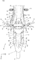
- FIG. 2 is a plan view showing the front part of the motorcycle 10.
- the front fender 41 passes between the left and right fork tubes 31 of the front fork 12 and extends longitudinally (along a front-rear direction). To the left and right of the rear part of the front fender 41 are disposed the pair of left and right shrouds 42, which laterally wide open at their front side and gradually narrow rearwardly. Part of a relative wind whose flow is formed by the front fender 41 is guided to the inside of the left and right shrouds 42 and is made to impinge on the left and right radiators 27 and 28 (see FIG. 4 ).
- reference numerals 51 and 52 denote grips provided at both end parts of the handlebar 37.
- Reference numeral 53 denotes a clutch lever provided at the left side of the handlebar 37.
- Reference numeral 54 denotes a front brake lever provided at the right side of the handlebar 37.
- Reference numeral 56 denotes a cap that seals a filler port of the fuel tank 25.
- Reference numeral 57 denotes an exhaust pipe extending from a front part of the engine 16.
- Reference numeral 58 denotes a heat barrier cover that covers the exhaust pipe 57 from a lateral side.
- Reference numerals 61 denote steps for the driver.
- Reference numeral 62 denotes a gear change pedal and reference numeral 63 denotes a rear brake pedal.
- FIG. 3 is a front view showing the motorcycle 10.
- An upper part of the front fender 41 (the part in front of the left and right fork tubes 31) overlaps with the bottom bridge 33, upper parts of the radiators 27 and 28, a lower end part of the number plate 38, and the left and right fork tubes 31 in front view.
- Left and right louver parts 44a and 44b formed in the left and right inner shrouds 44 are disposed in front of the left and right radiators 27 and 28.
- a relative wind passes through the louver parts 44a and 44b from the front of the vehicle and flows rearwardly to the radiators 27 and 28.
- a lower end part of the right radiator 28 is located vertically higher than a lower end part of the left radiator 27 in order to avoid interference with the exhaust pipe 57, which protrudes toward the right side.
- the right radiator 28 is formed with a smaller vertical extent than the left radiator 27.
- the vertical extent of the right louver part 44b is smaller than the left louver part 44a.
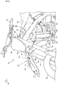
- FIG. 4 is a cross-sectional view taken along line IV-IV in FIG. 1 , and is a diagram obtained by cutting along a vertical plane passing through the highest part of the front fender 41.
- FIG. 5 is an enlarged view of the section around the front fender 41 in FIG. 4 .
- the front fender 41 includes a main body part 41a having a substantially inverted U-shaped section open downwardly, left and right step parts 41b extending laterally from left and right end parts of the main body part 41a integrally, and lower vertical wall parts 41h extending substantially downward from side edges of the step parts 41b integrally.
- the front fender 41 is fixed to the lower part of the bottom bridge 33 by plural bolts 65.
- the main body part 41a is composed of a mountain-shaped part 41d that has a ridge line 41c as a laterally central top part and bends into a mountain shape to protrude upward, and upper vertical wall parts 41e extending integrally from both edges of the mountain-shaped part 41d obliquely laterally and downwardly.
- the mountain-shaped part 41d is formed of left-right inclined parts 41f extending obliquely laterally and downwardly from the ridge line 41c.
- the step part 41b and the upper vertical wall part 41e form a groove whose section is generally L-shaped, and form a wind guide path that guides a relative wind in a predetermined direction (direction toward the radiators 27 and 28 and the engine 16). Furthermore, the left-right inclined parts 41f play a role in distributing the relative wind to the sides of the left and right step parts 41b.
- the lower vertical wall parts 41h serve as reinforcing parts that enhance the rigidity of the step parts 41b (and hence the front fender 41), and also enhance the mud guard performance in preventing mud and so forth which is splashed up by the front wheel 13 (see FIG. 1 ) from flying to the rider side.
- Left and right fork clearance parts 41j that are located between the left and right fork tubes 31 and are close to these fork tubes 31 are also formed in the front fender 41.
- Laterally inner parts (substantially, the inner halves) of the left and right radiators 27 and 28 are disposed behind the left and right fork tubes 31, and laterally outer parts (substantially, the outer halves) are oriented toward the front without being blocked by the fork tubes 31.
- the radiator 27 is composed of an upper tank 27a provided at an upper end part, a lower tank 27b provided at a lower end part, and a radiator core 27c disposed between the upper tank 27a and the lower tank 27b, and has, in the upper tank 27a, a water filler port 27d and a radiator cap 67 that seals the water filler port 27d.
- the radiator 28 is composed of an upper tank 28a provided at an upper end part, a lower tank 28b provided at a lower end part, and a radiator core 28c disposed between the upper tank 28a and the lower tank 28b, and has, in the upper tank 28a, a water filler port 28d and a radiator cap 68 that seals the water filler port 28d.
- the upper tank 27a, the lower tank 27b, the upper tank 28a, and the lower tank 28b are parts in which coolant is temporarily stored.
- the radiator cores 27c and 28c are heat dissipating parts that connect the upper tank 27a and the lower tank 27b and connect the upper tank 28a and the lower tank 28b, respectively, by plural conduits through which the coolant passes, and are provided with fins between the respective conduits.
- the main body parts of the radiators 27 and 28, that is, the parts excluding the water filler ports 27d and 28d and the radiator caps 67 and 68, are disposed lower than the bottom bridge 33.
- a predetermined flow can be formed in a relative wind flowing close to the surface of the front fender 41, and the relative wind can be made to flow toward the radiators 27 and 28 and the engine 16 (see FIG. 1 ).
- the step part 41b of the front fender 41 is formed to extend toward obliquely upwardly and rearwardly generally (but not exactly) parallel to an upper edge contour line 41k that is an upper edge line of the front fender 41 in side view, and extend obliquely downwardly and rearwardly at a position near to the front side of the fork tubes 31.
- a rear inclined part 41m is formed to extend in a straight line obliquely downwardly and rearwardly in side view.
- An extension 71 of the rear inclined part 41m is inclined relative to a front surface 31a of the fork tube 31 by an angle ⁇ .
- the angle ⁇ is about 90° and the extension 71 passes through the radiators 27 and 28 (see FIG. 4 regarding the radiator 28) and the cylinder unit 16A of the engine 16 in side view.
- the angle ⁇ is equal to or smaller than 90°, and favourably the angle ⁇ is equal to or smaller than 100°.
- step parts 41b By providing the step parts 41b in this manner, a relative wind that impinges on left and right side parts of the front fender 41 can be made to flow obliquely downwardly and rearwardly along the step parts 41b. Furthermore, the height difference between the upper edge contour line 41k and the step parts 41b gradually becomes larger in the rearward direction. Because the height difference gradually changes in this manner, the flowing of the relative wind along the step parts 41b can be facilitated.
- the upper vertical wall parts 41e (or the valley lines 41n passing through the boundary between the upper vertical wall part 41e and the step part 41b) are formed to be located laterally further outward when the position is closer to the rear side. This allows the relative wind flowing along the upper vertical wall part 41e and the step part 41b to be oriented to flow outward more as the relative wind moves rearward.
- FIG. 6 is a cross-sectional view taken along line VI-VI in FIG. 1 and is a diagram showing a cross-section parallel to the axes of the fork tubes 31.
- FIG. 7 is an enlarged view of the section around the front fender 41 in FIG. 6 .
- a flat part 41p that couples laterally inner parts of the left-right inclined parts 41f on both sides is formed in the main body part 41a.
- the step parts 41b are inclined to the horizontal (shown by horizontal line 73) by an angle ⁇ so that the laterally outer part is lower than the laterally inner part.
- the angle ⁇ is, for example, 0 to 20° and preferably 0 to 15°.
- the left and right step parts 41b extend toward the left and right fork tubes 31, respectively.
- Wind guide operation by the above-described front fender 41 will now be described with FIGS. 8 to 10 .
- FIG. 8 is a side view showing the wind guide operation of the front fender 41.
- FIG. 9 is a plan view showing the wind guide operation of the front fender 41.
- FIG. 10 is a perspective view showing the wind guide operation of the front fender 41.
- a relative wind moving from the front of the vehicle toward the motorcycle 10 travels as shown by an arrow A and impinges on the front side of the step part 41b of the front fender 41 to begin to travel along the step part 41b as shown by an arrow B.
- the relative wind travels along the step part 41b obliquely upwardly and rearwardly as shown by an arrow C and then travels obliquely downwardly and rearwardly along the rear inclined part 41m of the rear end part of the step part 41b as shown by an arrow D.
- the relative wind travels along the extension 71 of the rear inclined part 41m obliquely downwardly and rearwardly in a substantially straight line manner while moving around the fork tube 31 of the front fork 12. Then, the relative wind passes through the radiator core 27c of the radiator 27 and impinges on the cylinder unit 16A of the engine 16 as shown by an arrow F. As a result, the radiator 27 and the engine 16 are cooled. Similarly, on the right side of the front fender 41, the relative wind passes through the radiator 28 (see FIG. 4 ) and impinges on the cylinder unit 16A of the engine 16, so that the radiator 28 and the engine 16 are cooled.
- a relative wind moving from the front of the vehicle toward the motorcycle 10 travels as shown by arrows H and reaches the left and right step parts 41b of the front fender 41 as shown by arrows J to travel along the step parts 41b and the upper vertical wall parts 41e as shown by arrows K.
- the relative wind moves around the left and right fork tubes 31 from over the step parts 41b and reaches the radiators 27 and 28 (see FIG. 4 ) in the left and right shrouds 42.
- the relative wind flows to the engine 16 (see FIG. 8 ).
- the radiators 27 and 28 and the engine 16 are thereby cooled.
- a relative wind moving from the front of the vehicle toward the motorcycle 10 as shown by an arrow P impinges on the left-right inclined parts 41f (in FIG. 10 , only the left inclined part 41f is shown) of the main body part 41a of the front fender 41 and is distributed to the left and right sides to reach the step parts 41b from the left-right inclined parts 41f as shown by arrows Q and R. Then, as shown by arrows K and L, the relative wind travels rearward along the step parts 41b and moves around the fork tubes 31 from rear parts of the step parts 41b to reach the radiators 27 and 28 and the engine 16.
- the upper vertical wall parts 41e and the step parts 41b of the front fender 41 cooperate with each other.
- the relative wind can be directed to the radiators 27 and 28 (see FIG. 4 regarding the radiator 28) and the engine 16.
- the motorcycle 10 (which is an example of a saddle-type vehicle) including the vehicle body frame 11 including the head pipe 21 and the main frames 22 extending downwardly and rearwardly from the head pipe 21, the engine 16 disposed below the main frames 22, the steering stem 34 as the steering shaft pivotally supported by the head pipe 21 so as to be steerable, the bottom bridge 33 attached to a lower end part of this steering stem 34, the pair of left and right fork tubes 31 that are attached to left and right end parts of this bottom bridge 33 and support the front wheel 13 at lower end parts thereof, and the front fender 41 fixed to the bottom bridge 33 or the fork tubes 31, the front fender 41 includes the main body part 41a as a front fender main body part having a substantially inverted U-shaped section, open downwardly, and the step parts 41b extending from the left and right end parts of this main body part 41a toward both lateral sides, at least at the part of the front fender 41 to the front of the
- the step parts 41b are formed to extend from the front part of the front fender 41 upwardly and rearwardly along the upper edge contour line 41k in side view of the front fender 41 and then extend downwardly and rearwardly at a part near the front side of the fork tubes 31.
- a relative wind that impinges on left and right parts of the front fender 41 can be made to flow with orientations along the step parts 41b downwardly and rearwardly.
- the relative wind can be made to impinge on the engine 16 disposed to the rear of the step parts 41b, and cooling of the engine 16 can be promoted. Because this is achieved as a result of the front fender 41 having the above-described simple shape, increases in the weight and the number of parts of the front fender 41 are not caused. Therefore, weight reduction and cost reduction can be achieved.
- the height difference between the main body part 41a and the step parts 41b gradually becomes larger in the direction from the front side of the front fender 41 toward the rear side. Therefore, the flowing of the relative wind along the step parts 41b can be facilitated.
- the angle ⁇ of the rear end parts (rear inclined parts 41m) of the step parts 41b with respect to the fork tubes 31 is set to substantially a right angle or a smaller angle. Therefore, the relative wind is made to flow from the rear end parts of the step parts 41b toward the vehicle body rear side at substantially a right angle or a smaller angle to the fork tubes 31. This can facilitate guiding of the relative wind to the side of the engine 16.
- the upper vertical wall parts 41e as left and right vertical wall parts forming the main body part 41a located laterally inside of the step parts 41b are formed to be located laterally further outward when the position is closer to the rear side. This allows the relative wind guided along the step parts 41b to be oriented to flow more outward as the relative wind moves toward the rear side by the upper vertical wall parts 41e.
- the amount of relative wind that impinges on a headlight and the fork tubes 31 and flows upward can be reduced and consequently the amount of wind flowing downwardly and rearwardly to the engine 16 can be increased.
- the lower vertical wall parts 41h as step-part vertical wall parts extending downward are provided at laterally outer edge parts of the step parts 41b. Therefore, the rigidity of the step parts 41b and hence the rigidity of the front fender 41 can be enhanced by the lower vertical wall parts 41h. In addition, the mud guard performance can be improved.
- the vehicle body frame 11 includes the down-frame 23 extending downwardly and rearwardly from the head pipe 21.
- the radiators 27 and 28 are each provided at a position that is offset to at least one of the left and right of the down-frame 23 and is lower than the bottom bridge 33, and the extensions 71 of the rear inclined parts 41m as the rear end parts of the step parts 41b pass through the radiator cores 27c and 28c of the radiators 27 and 28 in side view. Therefore, the relative wind can be effectively guided to the radiator cores 27c and 28c and the performance of cooling the radiators 27 and 28 can be improved.
- the upper surface of the front fender 41 is formed to bend in such a manner that the laterally central part protrudes upward. Therefore, the relative wind that impinges on the laterally central part of the front fender 41 can be distributed to the left and right sides by the protruding upper surface (left and right left-right inclined parts 41f) and then be guided to be oriented downwardly and rearwardly by the left and right step parts 41b. This can further improve the performance of cooling the engine 16.
- the above-described embodiment shows one specific aspect of the present invention, and modifications and applications can be made without departing from the scope of the present invention defined by the appended claims.
- the present invention is also not limited to application to the motorcycle 10, and can also be applied to saddle-type vehicles other than the motorcycle 10.
- saddle-type vehicles includes vehicles where a rider rides astride the vehicle body, and included not only motorcycles (including motorized bicycles) but also three-wheeled vehicles and four-wheeled vehicles categorized as ATV (all-terrain vehicles).
Landscapes
- Engineering & Computer Science (AREA)
- Mechanical Engineering (AREA)
- Chemical & Material Sciences (AREA)
- Combustion & Propulsion (AREA)
- Transportation (AREA)
- Automatic Cycles, And Cycles In General (AREA)
Claims (6)
- Véhicule de type à selle, ledit véhicule incluant un châssis de corps de véhicule (11) comprenant un tuyau de tête (21), un châssis principal (22) s'étendant vers le bas et vers l'arrière à partir du tuyau de tête (21) et un châssis plongeant (23) s'étendant vers le bas et vers l'arrière à partir du tuyau de tête (21), un moteur (16) disposé en dessous du châssis principal (22), un arbre de direction (34) supporté en pivotement par le tuyau de tête (21) de façon à pouvoir être orienté, un pont inférieur (33) fixé à une partie d'extrémité inférieure de l'arbre de direction (34), une paire de tubes fourchés de gauche et de droite (31) qui sont fixés à des parties d'extrémité de gauche et de droite du pont inférieur (33) et supportent une roue avant (13) dans des parties d'extrémité inférieures des tubes fourchés (31) de sorte que la roue avant (13) puisse se déplacer de manière générale verticalement, et un garde-boue avant (41) fixé au pont inférieur (33) ou aux tubes fourchés (31),
dans lequel le garde-boue avant (41) inclut une partie de corps principal de garde-boue (41a) ayant une section sensiblement en forme de U à l'envers, ouverte vers le bas, et des parties de marchepied (41b) s'étendant à partir des parties d'extrémité de gauche et de droite de la partie de corps principal (41a) du garde-boue avant vers les deux parois latérales, au moins dans une partie du garde-boue avant (41) vers l'avant de la paire de tubes fourchés de gauche et de droite (31),
dans lequel les parties de marchepied (41b) sont formées pour s'étendre à partir d'une partie avant du garde-boue avant (41) vers le haut et vers l'arrière le long d'une ligne de contour de bord supérieur (41k) en vue latérale du garde-boue avant (41) et s'étendre ensuite vers le bas et vers l'arrière dans une partie proche du côté avant des tubes fourchés (31),
caractérisé en ce que des radiateurs (27, 28) sont prévus chacun dans une position qui est décalée vers au moins la gauche ou la droite du châssis plongeant (23) et est plus basse que le pont inférieur (33), et des extensions (71) de parties d'extrémité arrière (41m) des parties de marchepied (41b) passent à travers les noyaux (27c, 28c) des radiateurs (27, 28) en vue latérale. - Véhicule du type à selle selon la revendication 1, caractérisé en ce qu'une différence de hauteur entre la partie de corps principale (41a) du garde-boue avant et les parties de marchepied (41b) devient graduellement plus grande dans une direction allant du côté avant du garde-boue avant (41) vers un côté arrière.
- Véhicule du type à selle selon la revendication 1 ou 2, caractérisé en ce qu'un angle θ de parties d'extrémité arrière des parties de marchepied (41b) par rapport aux tubes fourchés (31) est réglé à un angle sensiblement droit ou à un angle plus petit.
- Véhicule du type à selle selon l'une quelconque des revendications 1 à 3, caractérisé en ce que des parties de paroi verticales de gauche et de droite (41e) formant la partie de corps principale (41a) du garde-boue avant située latéralement à l'intérieur des parties de marchepied (41b) sont formées pour être situées latéralement plus loin vers l'extérieur lorsqu'une position est plus proche d'un côté arrière.
- Véhicule du type à selle selon l'une quelconque des revendications 1 à 4, caractérisé en ce que les parties de paroi verticales (41h) des parties de marchepied s'étendant vers le bas sont disposées dans des parties de bord latéralement externes des parties de marchepied (41b).
- Véhicule du type à selle selon l'une quelconque des revendications 1 à 5, caractérisé en ce qu'une surface supérieure du garde-boue avant (41) est formée pour se recourber de manière telle qu'une partie latéralement centrale fasse saillie vers le haut.
Applications Claiming Priority (1)
| Application Number | Priority Date | Filing Date | Title |
|---|---|---|---|
| JP2014237589A JP6254511B2 (ja) | 2014-11-25 | 2014-11-25 | 鞍乗り型車両のフロントフェンダー |
Publications (2)
| Publication Number | Publication Date |
|---|---|
| EP3025945A1 EP3025945A1 (fr) | 2016-06-01 |
| EP3025945B1 true EP3025945B1 (fr) | 2018-03-14 |
Family
ID=54697488
Family Applications (1)
| Application Number | Title | Priority Date | Filing Date |
|---|---|---|---|
| EP15195855.0A Active EP3025945B1 (fr) | 2014-11-25 | 2015-11-23 | Garde-boue avant de véhicule à selle |
Country Status (5)
| Country | Link |
|---|---|
| US (1) | US10202160B2 (fr) |
| EP (1) | EP3025945B1 (fr) |
| JP (1) | JP6254511B2 (fr) |
| CA (1) | CA2910617C (fr) |
| ES (1) | ES2665947T3 (fr) |
Families Citing this family (9)
| Publication number | Priority date | Publication date | Assignee | Title |
|---|---|---|---|---|
| JP6126954B2 (ja) * | 2013-09-11 | 2017-05-10 | 本田技研工業株式会社 | 鞍乗型車両 |
| JP6749979B2 (ja) * | 2018-09-27 | 2020-09-02 | 本田技研工業株式会社 | 鞍乗り型電動車両 |
| US10647374B1 (en) * | 2018-12-18 | 2020-05-12 | Kawasaki Jukogyo Kabushiki Kaisha | Straddle type vehicle and rear fender |
| JP7274860B2 (ja) * | 2018-12-26 | 2023-05-17 | カワサキモータース株式会社 | 自動二輪車のエンジン冷却構造 |
| IT201900005674A1 (it) | 2019-04-12 | 2020-10-12 | Rossi&Bossi S R L | Bicicletta con telaio a doppio tubolare. |
| IT201900005670A1 (it) | 2019-04-12 | 2020-10-12 | Rossi&Bossi S R L | Bicicletta con binario. |
| USD935967S1 (en) * | 2019-06-11 | 2021-11-16 | Zhejiang Apollo Motorcycle Manufacturing Co., Ltd. | Vehicle head panel |
| EP4117986A1 (fr) * | 2020-03-11 | 2023-01-18 | TVS Motor Company Limited | Refroidissement de composants générateurs de chaleur dans des véhicules électriques |
| JP2023038648A (ja) * | 2021-09-07 | 2023-03-17 | ヤマハ発動機株式会社 | 鞍乗型車両 |
Family Cites Families (18)
| Publication number | Priority date | Publication date | Assignee | Title |
|---|---|---|---|---|
| JPS58112691U (ja) * | 1981-09-25 | 1983-08-01 | 本田技研工業株式会社 | 2輪車のフロントフエンダ装置 |
| JPS60110187U (ja) * | 1983-12-29 | 1985-07-26 | 本田技研工業株式会社 | 自動二輪車のフロントフエンダ− |
| JPS61113575A (ja) * | 1984-11-08 | 1986-05-31 | 本田技研工業株式会社 | フロントフオ−ク付車両のフロントフエンダ |
| JP4048039B2 (ja) * | 2001-09-07 | 2008-02-13 | 本田技研工業株式会社 | 自動二輪車のフロントバイザ取付け構造 |
| US6651769B2 (en) * | 2002-01-03 | 2003-11-25 | Next World Design, Inc. | Fender assembly and system for racing motorcycle vehicles |
| JP4476720B2 (ja) * | 2004-07-02 | 2010-06-09 | 本田技研工業株式会社 | 自動2輪車用フェンダー構造 |
| US8061468B2 (en) | 2006-11-15 | 2011-11-22 | Yamaha Hatsudoki Kabushiki Kaisha | Vehicle |
| JP2008179336A (ja) * | 2006-12-27 | 2008-08-07 | Yamaha Motor Co Ltd | 車両 |
| US7686116B2 (en) * | 2006-12-27 | 2010-03-30 | Yamaha Hatsudoki Kabushiki Kaisha | Vehicle |
| JP2008162517A (ja) * | 2006-12-28 | 2008-07-17 | Yamaha Motor Co Ltd | 鞍乗型車両 |
| JP5001027B2 (ja) * | 2007-03-02 | 2012-08-15 | 本田技研工業株式会社 | 自動二輪車のフェンダ支持構造 |
| JP3154637U (ja) * | 2008-08-08 | 2009-10-22 | ヤマハ発動機株式会社 | 鞍乗り型車両 |
| JP5690706B2 (ja) * | 2011-11-16 | 2015-03-25 | 本田技研工業株式会社 | 鞍乗型車両のラジエータ構造 |
| JP5816534B2 (ja) * | 2011-11-16 | 2015-11-18 | 本田技研工業株式会社 | 鞍乗型車両 |
| PE20142199A1 (es) * | 2012-02-16 | 2015-01-18 | Honda Motor Co Ltd | Estructura del guardabarros delantero en vehiculo automatico de dos ruedas |
| JP6196083B2 (ja) * | 2013-07-10 | 2017-09-13 | 本田技研工業株式会社 | 自動二輪車 |
| JP6140556B2 (ja) * | 2013-07-10 | 2017-05-31 | 本田技研工業株式会社 | 自動二輪車 |
| US9440697B1 (en) * | 2015-08-24 | 2016-09-13 | Kawasaki Jukogyo Kabushiki Kaisha | Motorcycle front structure |
-
2014
- 2014-11-25 JP JP2014237589A patent/JP6254511B2/ja not_active Expired - Fee Related
-
2015
- 2015-10-28 CA CA2910617A patent/CA2910617C/fr not_active Expired - Fee Related
- 2015-11-17 US US14/943,759 patent/US10202160B2/en active Active
- 2015-11-23 EP EP15195855.0A patent/EP3025945B1/fr active Active
- 2015-11-23 ES ES15195855.0T patent/ES2665947T3/es active Active
Non-Patent Citations (1)
| Title |
|---|
| None * |
Also Published As
| Publication number | Publication date |
|---|---|
| CA2910617C (fr) | 2018-06-19 |
| US20160144921A1 (en) | 2016-05-26 |
| CA2910617A1 (fr) | 2016-05-25 |
| ES2665947T3 (es) | 2018-04-30 |
| US10202160B2 (en) | 2019-02-12 |
| JP2016097864A (ja) | 2016-05-30 |
| EP3025945A1 (fr) | 2016-06-01 |
| JP6254511B2 (ja) | 2017-12-27 |
Similar Documents
| Publication | Publication Date | Title |
|---|---|---|
| EP3025945B1 (fr) | Garde-boue avant de véhicule à selle | |
| US9663175B2 (en) | Front fender structure for saddle-ride type vehicle | |
| CN100453391C (zh) | 车辆 | |
| US8783399B2 (en) | Saddle-riding type vehicle including multi-part shroud | |
| US9580142B2 (en) | Cooling structure for saddle-type vehicle | |
| JP6259467B2 (ja) | 鞍乗型車両 | |
| JP5916456B2 (ja) | 鞍乗り型車両のラジエータ用排風構造 | |
| JP6147540B2 (ja) | 鞍乗り型車両 | |
| CN106005137A (zh) | 跨骑式车辆 | |
| EP3680157B1 (fr) | Véhicule à enfourcher | |
| US9328703B2 (en) | Air intake system of saddle-ride type vehicle | |
| EP2481657B1 (fr) | Véhicule à monture de selle | |
| JP2024155427A (ja) | アンダーカウル | |
| WO2018225199A1 (fr) | Véhicule à selle | |
| EP2910459B1 (fr) | Structure d'enveloppe de radiateur | |
| JP7056352B2 (ja) | フロントカウル構造及び自動二輪車 | |
| JP7592179B2 (ja) | 空気流入用の前面開口部を備えたフェアリング付きモーターサイクル | |
| JP2017074847A (ja) | 自動二輪車のフロントフェンダの導風構造 | |
| TWI584986B (zh) | 跨騎型車輛 | |
| JP7528654B2 (ja) | フロントカウル | |
| JP5883775B2 (ja) | 鞍乗型車両の導風構造 | |
| EP2712795B1 (fr) | Véhicule de type à enfourcher | |
| JP7661386B2 (ja) | 鞍乗り型車両 | |
| CN110325434B (zh) | 跨骑型车辆 | |
| JP6124602B2 (ja) | 鞍乗り型車両 |
Legal Events
| Date | Code | Title | Description |
|---|---|---|---|
| PUAI | Public reference made under article 153(3) epc to a published international application that has entered the european phase |
Free format text: ORIGINAL CODE: 0009012 |
|
| 17P | Request for examination filed |
Effective date: 20151123 |
|
| AK | Designated contracting states |
Kind code of ref document: A1 Designated state(s): AL AT BE BG CH CY CZ DE DK EE ES FI FR GB GR HR HU IE IS IT LI LT LU LV MC MK MT NL NO PL PT RO RS SE SI SK SM TR |
|
| AX | Request for extension of the european patent |
Extension state: BA ME |
|
| 17Q | First examination report despatched |
Effective date: 20170317 |
|
| GRAP | Despatch of communication of intention to grant a patent |
Free format text: ORIGINAL CODE: EPIDOSNIGR1 |
|
| INTG | Intention to grant announced |
Effective date: 20170919 |
|
| GRAS | Grant fee paid |
Free format text: ORIGINAL CODE: EPIDOSNIGR3 |
|
| GRAA | (expected) grant |
Free format text: ORIGINAL CODE: 0009210 |
|
| AK | Designated contracting states |
Kind code of ref document: B1 Designated state(s): AL AT BE BG CH CY CZ DE DK EE ES FI FR GB GR HR HU IE IS IT LI LT LU LV MC MK MT NL NO PL PT RO RS SE SI SK SM TR |
|
| REG | Reference to a national code |
Ref country code: GB Ref legal event code: FG4D |
|
| REG | Reference to a national code |
Ref country code: CH Ref legal event code: EP Ref country code: AT Ref legal event code: REF Ref document number: 978606 Country of ref document: AT Kind code of ref document: T Effective date: 20180315 |
|
| REG | Reference to a national code |
Ref country code: IE Ref legal event code: FG4D |
|
| REG | Reference to a national code |
Ref country code: DE Ref legal event code: R096 Ref document number: 602015008725 Country of ref document: DE |
|
| REG | Reference to a national code |
Ref country code: ES Ref legal event code: FG2A Ref document number: 2665947 Country of ref document: ES Kind code of ref document: T3 Effective date: 20180430 |
|
| REG | Reference to a national code |
Ref country code: NL Ref legal event code: MP Effective date: 20180314 |
|
| REG | Reference to a national code |
Ref country code: LT Ref legal event code: MG4D |
|
| PG25 | Lapsed in a contracting state [announced via postgrant information from national office to epo] |
Ref country code: CY Free format text: LAPSE BECAUSE OF FAILURE TO SUBMIT A TRANSLATION OF THE DESCRIPTION OR TO PAY THE FEE WITHIN THE PRESCRIBED TIME-LIMIT Effective date: 20180314 Ref country code: LT Free format text: LAPSE BECAUSE OF FAILURE TO SUBMIT A TRANSLATION OF THE DESCRIPTION OR TO PAY THE FEE WITHIN THE PRESCRIBED TIME-LIMIT Effective date: 20180314 Ref country code: FI Free format text: LAPSE BECAUSE OF FAILURE TO SUBMIT A TRANSLATION OF THE DESCRIPTION OR TO PAY THE FEE WITHIN THE PRESCRIBED TIME-LIMIT Effective date: 20180314 Ref country code: NO Free format text: LAPSE BECAUSE OF FAILURE TO SUBMIT A TRANSLATION OF THE DESCRIPTION OR TO PAY THE FEE WITHIN THE PRESCRIBED TIME-LIMIT Effective date: 20180614 Ref country code: HR Free format text: LAPSE BECAUSE OF FAILURE TO SUBMIT A TRANSLATION OF THE DESCRIPTION OR TO PAY THE FEE WITHIN THE PRESCRIBED TIME-LIMIT Effective date: 20180314 |
|
| REG | Reference to a national code |
Ref country code: AT Ref legal event code: MK05 Ref document number: 978606 Country of ref document: AT Kind code of ref document: T Effective date: 20180314 |
|
| PG25 | Lapsed in a contracting state [announced via postgrant information from national office to epo] |
Ref country code: RS Free format text: LAPSE BECAUSE OF FAILURE TO SUBMIT A TRANSLATION OF THE DESCRIPTION OR TO PAY THE FEE WITHIN THE PRESCRIBED TIME-LIMIT Effective date: 20180314 Ref country code: SE Free format text: LAPSE BECAUSE OF FAILURE TO SUBMIT A TRANSLATION OF THE DESCRIPTION OR TO PAY THE FEE WITHIN THE PRESCRIBED TIME-LIMIT Effective date: 20180314 Ref country code: LV Free format text: LAPSE BECAUSE OF FAILURE TO SUBMIT A TRANSLATION OF THE DESCRIPTION OR TO PAY THE FEE WITHIN THE PRESCRIBED TIME-LIMIT Effective date: 20180314 Ref country code: BG Free format text: LAPSE BECAUSE OF FAILURE TO SUBMIT A TRANSLATION OF THE DESCRIPTION OR TO PAY THE FEE WITHIN THE PRESCRIBED TIME-LIMIT Effective date: 20180614 Ref country code: GR Free format text: LAPSE BECAUSE OF FAILURE TO SUBMIT A TRANSLATION OF THE DESCRIPTION OR TO PAY THE FEE WITHIN THE PRESCRIBED TIME-LIMIT Effective date: 20180615 |
|
| PG25 | Lapsed in a contracting state [announced via postgrant information from national office to epo] |
Ref country code: AL Free format text: LAPSE BECAUSE OF FAILURE TO SUBMIT A TRANSLATION OF THE DESCRIPTION OR TO PAY THE FEE WITHIN THE PRESCRIBED TIME-LIMIT Effective date: 20180314 Ref country code: PL Free format text: LAPSE BECAUSE OF FAILURE TO SUBMIT A TRANSLATION OF THE DESCRIPTION OR TO PAY THE FEE WITHIN THE PRESCRIBED TIME-LIMIT Effective date: 20180314 Ref country code: RO Free format text: LAPSE BECAUSE OF FAILURE TO SUBMIT A TRANSLATION OF THE DESCRIPTION OR TO PAY THE FEE WITHIN THE PRESCRIBED TIME-LIMIT Effective date: 20180314 Ref country code: NL Free format text: LAPSE BECAUSE OF FAILURE TO SUBMIT A TRANSLATION OF THE DESCRIPTION OR TO PAY THE FEE WITHIN THE PRESCRIBED TIME-LIMIT Effective date: 20180314 Ref country code: EE Free format text: LAPSE BECAUSE OF FAILURE TO SUBMIT A TRANSLATION OF THE DESCRIPTION OR TO PAY THE FEE WITHIN THE PRESCRIBED TIME-LIMIT Effective date: 20180314 |
|
| PG25 | Lapsed in a contracting state [announced via postgrant information from national office to epo] |
Ref country code: SK Free format text: LAPSE BECAUSE OF FAILURE TO SUBMIT A TRANSLATION OF THE DESCRIPTION OR TO PAY THE FEE WITHIN THE PRESCRIBED TIME-LIMIT Effective date: 20180314 Ref country code: SM Free format text: LAPSE BECAUSE OF FAILURE TO SUBMIT A TRANSLATION OF THE DESCRIPTION OR TO PAY THE FEE WITHIN THE PRESCRIBED TIME-LIMIT Effective date: 20180314 Ref country code: AT Free format text: LAPSE BECAUSE OF FAILURE TO SUBMIT A TRANSLATION OF THE DESCRIPTION OR TO PAY THE FEE WITHIN THE PRESCRIBED TIME-LIMIT Effective date: 20180314 Ref country code: CZ Free format text: LAPSE BECAUSE OF FAILURE TO SUBMIT A TRANSLATION OF THE DESCRIPTION OR TO PAY THE FEE WITHIN THE PRESCRIBED TIME-LIMIT Effective date: 20180314 |
|
| REG | Reference to a national code |
Ref country code: DE Ref legal event code: R097 Ref document number: 602015008725 Country of ref document: DE |
|
| PG25 | Lapsed in a contracting state [announced via postgrant information from national office to epo] |
Ref country code: PT Free format text: LAPSE BECAUSE OF FAILURE TO SUBMIT A TRANSLATION OF THE DESCRIPTION OR TO PAY THE FEE WITHIN THE PRESCRIBED TIME-LIMIT Effective date: 20180716 |
|
| PLBE | No opposition filed within time limit |
Free format text: ORIGINAL CODE: 0009261 |
|
| STAA | Information on the status of an ep patent application or granted ep patent |
Free format text: STATUS: NO OPPOSITION FILED WITHIN TIME LIMIT |
|
| PG25 | Lapsed in a contracting state [announced via postgrant information from national office to epo] |
Ref country code: DK Free format text: LAPSE BECAUSE OF FAILURE TO SUBMIT A TRANSLATION OF THE DESCRIPTION OR TO PAY THE FEE WITHIN THE PRESCRIBED TIME-LIMIT Effective date: 20180314 |
|
| 26N | No opposition filed |
Effective date: 20181217 |
|
| PG25 | Lapsed in a contracting state [announced via postgrant information from national office to epo] |
Ref country code: SI Free format text: LAPSE BECAUSE OF FAILURE TO SUBMIT A TRANSLATION OF THE DESCRIPTION OR TO PAY THE FEE WITHIN THE PRESCRIBED TIME-LIMIT Effective date: 20180314 |
|
| PGFP | Annual fee paid to national office [announced via postgrant information from national office to epo] |
Ref country code: IT Payment date: 20181130 Year of fee payment: 4 Ref country code: ES Payment date: 20181203 Year of fee payment: 4 Ref country code: FR Payment date: 20181123 Year of fee payment: 4 |
|
| REG | Reference to a national code |
Ref country code: CH Ref legal event code: PL |
|
| PG25 | Lapsed in a contracting state [announced via postgrant information from national office to epo] |
Ref country code: LU Free format text: LAPSE BECAUSE OF NON-PAYMENT OF DUE FEES Effective date: 20181123 Ref country code: MC Free format text: LAPSE BECAUSE OF FAILURE TO SUBMIT A TRANSLATION OF THE DESCRIPTION OR TO PAY THE FEE WITHIN THE PRESCRIBED TIME-LIMIT Effective date: 20180314 |
|
| REG | Reference to a national code |
Ref country code: BE Ref legal event code: MM Effective date: 20181130 |
|
| REG | Reference to a national code |
Ref country code: IE Ref legal event code: MM4A |
|
| PG25 | Lapsed in a contracting state [announced via postgrant information from national office to epo] |
Ref country code: LI Free format text: LAPSE BECAUSE OF NON-PAYMENT OF DUE FEES Effective date: 20181130 Ref country code: CH Free format text: LAPSE BECAUSE OF NON-PAYMENT OF DUE FEES Effective date: 20181130 |
|
| PG25 | Lapsed in a contracting state [announced via postgrant information from national office to epo] |
Ref country code: IE Free format text: LAPSE BECAUSE OF NON-PAYMENT OF DUE FEES Effective date: 20181123 |
|
| PG25 | Lapsed in a contracting state [announced via postgrant information from national office to epo] |
Ref country code: BE Free format text: LAPSE BECAUSE OF NON-PAYMENT OF DUE FEES Effective date: 20181130 |
|
| REG | Reference to a national code |
Ref country code: DE Ref legal event code: R084 Ref document number: 602015008725 Country of ref document: DE |
|
| PG25 | Lapsed in a contracting state [announced via postgrant information from national office to epo] |
Ref country code: MT Free format text: LAPSE BECAUSE OF NON-PAYMENT OF DUE FEES Effective date: 20181123 |
|
| PG25 | Lapsed in a contracting state [announced via postgrant information from national office to epo] |
Ref country code: TR Free format text: LAPSE BECAUSE OF FAILURE TO SUBMIT A TRANSLATION OF THE DESCRIPTION OR TO PAY THE FEE WITHIN THE PRESCRIBED TIME-LIMIT Effective date: 20180314 |
|
| PG25 | Lapsed in a contracting state [announced via postgrant information from national office to epo] |
Ref country code: HU Free format text: LAPSE BECAUSE OF FAILURE TO SUBMIT A TRANSLATION OF THE DESCRIPTION OR TO PAY THE FEE WITHIN THE PRESCRIBED TIME-LIMIT; INVALID AB INITIO Effective date: 20151123 Ref country code: MK Free format text: LAPSE BECAUSE OF NON-PAYMENT OF DUE FEES Effective date: 20180314 |
|
| PG25 | Lapsed in a contracting state [announced via postgrant information from national office to epo] |
Ref country code: IS Free format text: LAPSE BECAUSE OF FAILURE TO SUBMIT A TRANSLATION OF THE DESCRIPTION OR TO PAY THE FEE WITHIN THE PRESCRIBED TIME-LIMIT Effective date: 20180714 |
|
| GBPC | Gb: european patent ceased through non-payment of renewal fee |
Effective date: 20191123 |
|
| PG25 | Lapsed in a contracting state [announced via postgrant information from national office to epo] |
Ref country code: IT Free format text: LAPSE BECAUSE OF NON-PAYMENT OF DUE FEES Effective date: 20191123 Ref country code: FR Free format text: LAPSE BECAUSE OF NON-PAYMENT OF DUE FEES Effective date: 20191130 Ref country code: GB Free format text: LAPSE BECAUSE OF NON-PAYMENT OF DUE FEES Effective date: 20191123 |
|
| REG | Reference to a national code |
Ref country code: ES Ref legal event code: FD2A Effective date: 20210414 |
|
| PG25 | Lapsed in a contracting state [announced via postgrant information from national office to epo] |
Ref country code: ES Free format text: LAPSE BECAUSE OF NON-PAYMENT OF DUE FEES Effective date: 20191124 |
|
| PGFP | Annual fee paid to national office [announced via postgrant information from national office to epo] |
Ref country code: DE Payment date: 20251022 Year of fee payment: 11 |