EP3026344A1 - Brûleur d'une turbine à gaz - Google Patents
Brûleur d'une turbine à gaz Download PDFInfo
- Publication number
- EP3026344A1 EP3026344A1 EP14194930.5A EP14194930A EP3026344A1 EP 3026344 A1 EP3026344 A1 EP 3026344A1 EP 14194930 A EP14194930 A EP 14194930A EP 3026344 A1 EP3026344 A1 EP 3026344A1
- Authority
- EP
- European Patent Office
- Prior art keywords
- burner
- order
- nozzles
- lobed shape
- trailing edge
- Prior art date
- Legal status (The legal status is an assumption and is not a legal conclusion. Google has not performed a legal analysis and makes no representation as to the accuracy of the status listed.)
- Granted
Links
Images



Classifications
-
- F—MECHANICAL ENGINEERING; LIGHTING; HEATING; WEAPONS; BLASTING
- F23—COMBUSTION APPARATUS; COMBUSTION PROCESSES
- F23R—GENERATING COMBUSTION PRODUCTS OF HIGH PRESSURE OR HIGH VELOCITY, e.g. GAS-TURBINE COMBUSTION CHAMBERS
- F23R3/00—Continuous combustion chambers using liquid or gaseous fuel
- F23R3/28—Continuous combustion chambers using liquid or gaseous fuel characterised by the fuel supply
- F23R3/286—Continuous combustion chambers using liquid or gaseous fuel characterised by the fuel supply having fuel-air premixing devices
-
- F—MECHANICAL ENGINEERING; LIGHTING; HEATING; WEAPONS; BLASTING
- F23—COMBUSTION APPARATUS; COMBUSTION PROCESSES
- F23R—GENERATING COMBUSTION PRODUCTS OF HIGH PRESSURE OR HIGH VELOCITY, e.g. GAS-TURBINE COMBUSTION CHAMBERS
- F23R3/00—Continuous combustion chambers using liquid or gaseous fuel
- F23R3/02—Continuous combustion chambers using liquid or gaseous fuel characterised by the air-flow or gas-flow configuration
- F23R3/04—Air inlet arrangements
- F23R3/10—Air inlet arrangements for primary air
- F23R3/12—Air inlet arrangements for primary air inducing a vortex
-
- F—MECHANICAL ENGINEERING; LIGHTING; HEATING; WEAPONS; BLASTING
- F23—COMBUSTION APPARATUS; COMBUSTION PROCESSES
- F23R—GENERATING COMBUSTION PRODUCTS OF HIGH PRESSURE OR HIGH VELOCITY, e.g. GAS-TURBINE COMBUSTION CHAMBERS
- F23R3/00—Continuous combustion chambers using liquid or gaseous fuel
- F23R3/02—Continuous combustion chambers using liquid or gaseous fuel characterised by the air-flow or gas-flow configuration
- F23R3/04—Air inlet arrangements
- F23R3/10—Air inlet arrangements for primary air
- F23R3/12—Air inlet arrangements for primary air inducing a vortex
- F23R3/14—Air inlet arrangements for primary air inducing a vortex by using swirl vanes
-
- F—MECHANICAL ENGINEERING; LIGHTING; HEATING; WEAPONS; BLASTING
- F23—COMBUSTION APPARATUS; COMBUSTION PROCESSES
- F23R—GENERATING COMBUSTION PRODUCTS OF HIGH PRESSURE OR HIGH VELOCITY, e.g. GAS-TURBINE COMBUSTION CHAMBERS
- F23R3/00—Continuous combustion chambers using liquid or gaseous fuel
- F23R3/02—Continuous combustion chambers using liquid or gaseous fuel characterised by the air-flow or gas-flow configuration
- F23R3/16—Continuous combustion chambers using liquid or gaseous fuel characterised by the air-flow or gas-flow configuration with devices inside the flame tube or the combustion chamber to influence the air or gas flow
- F23R3/18—Flame stabilising means, e.g. flame holders for after-burners of jet-propulsion plants
- F23R3/20—Flame stabilising means, e.g. flame holders for after-burners of jet-propulsion plants incorporating fuel injection means
-
- F—MECHANICAL ENGINEERING; LIGHTING; HEATING; WEAPONS; BLASTING
- F23—COMBUSTION APPARATUS; COMBUSTION PROCESSES
- F23R—GENERATING COMBUSTION PRODUCTS OF HIGH PRESSURE OR HIGH VELOCITY, e.g. GAS-TURBINE COMBUSTION CHAMBERS
- F23R3/00—Continuous combustion chambers using liquid or gaseous fuel
- F23R3/28—Continuous combustion chambers using liquid or gaseous fuel characterised by the fuel supply
-
- F—MECHANICAL ENGINEERING; LIGHTING; HEATING; WEAPONS; BLASTING
- F23—COMBUSTION APPARATUS; COMBUSTION PROCESSES
- F23R—GENERATING COMBUSTION PRODUCTS OF HIGH PRESSURE OR HIGH VELOCITY, e.g. GAS-TURBINE COMBUSTION CHAMBERS
- F23R3/00—Continuous combustion chambers using liquid or gaseous fuel
- F23R3/28—Continuous combustion chambers using liquid or gaseous fuel characterised by the fuel supply
- F23R3/283—Attaching or cooling of fuel injecting means including supports for fuel injectors, stems, or lances
-
- F—MECHANICAL ENGINEERING; LIGHTING; HEATING; WEAPONS; BLASTING
- F23—COMBUSTION APPARATUS; COMBUSTION PROCESSES
- F23R—GENERATING COMBUSTION PRODUCTS OF HIGH PRESSURE OR HIGH VELOCITY, e.g. GAS-TURBINE COMBUSTION CHAMBERS
- F23R3/00—Continuous combustion chambers using liquid or gaseous fuel
- F23R3/42—Continuous combustion chambers using liquid or gaseous fuel characterised by the arrangement or form of the flame tubes or combustion chambers
- F23R3/46—Combustion chambers comprising an annular arrangement of several essentially tubular flame tubes within a common annular casing or within individual casings
-
- F—MECHANICAL ENGINEERING; LIGHTING; HEATING; WEAPONS; BLASTING
- F23—COMBUSTION APPARATUS; COMBUSTION PROCESSES
- F23C—METHODS OR APPARATUS FOR COMBUSTION USING FLUID FUEL OR SOLID FUEL SUSPENDED IN A CARRIER GAS OR AIR
- F23C2900/00—Special features of, or arrangements for combustion apparatus using fluid fuels or solid fuels suspended in air; Combustion processes therefor
- F23C2900/07001—Air swirling vanes incorporating fuel injectors
-
- F—MECHANICAL ENGINEERING; LIGHTING; HEATING; WEAPONS; BLASTING
- F23—COMBUSTION APPARATUS; COMBUSTION PROCESSES
- F23R—GENERATING COMBUSTION PRODUCTS OF HIGH PRESSURE OR HIGH VELOCITY, e.g. GAS-TURBINE COMBUSTION CHAMBERS
- F23R2900/00—Special features of, or arrangements for continuous combustion chambers; Combustion processes therefor
- F23R2900/03341—Sequential combustion chambers or burners
Definitions
- the present invention relates to a burner of a gas turbine.
- the burner is arranged for quickly mixing a liquid or gas fuel with air or hot gas (cooling air is usually mixed as well), such that the mixture of fuel and air/hot gas auto ignites and combusts in a premixed fashion.
- the fuel and air/hot gas are usually supplied into one or more burners, which are located upstream of a combustion chamber; in the burner air/hot gas and fuel are mixed and the mixture is then combusted in a combustion chamber.
- the burners In order to quickly mix fuel and air/hot gas, the burners have a duct which includes structures creating turbulence.
- the air/hot gas passes through these structures acquiring turbulence; the fuel is injected in the turbulent flow such that quick mixing is achieved with the air/hot gas.
- the structures creating turbulence are referred to as vortex generators.
- EP 2 496 884 discloses vortex generators having walls with a substantially straight or curved leading edge and a trailing edge with a lobed shape.
- US 8 528 337 discloses nozzles with nozzle walls with a trailing edge having a first order lobed shape in turn defined by a second order lobed shape. For example figure 8 of US 8 528 337 shows this arrangement.
- the inventors have found a way to improve the performances in terms of mixing of the vortex generators of the kind described in EP 2 496 884 .
- An aspect of the invention includes providing a burner that provides better mixing performances than the burners of the prior art.
- the burner has a second order lobed shape only in the vicinity of the nozzles; this embodiment is easy and cheap to manufacture but at the same time allows quick mixing.
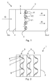
- these show a burner 1 of a gas turbine comprising a duct 2 and one or more vortex generators 3 extending in the duct 2.
- the vortex generators can be connected at one or more ends to the duct 2 and/or a central body, which is inserted into the duct.
- the burner 1 can be a reheat burner, i.e. a burner receiving hot gas still containing oxygen from another upstream burner; in this case the gas turbine configuration is typically but not exclusively a compressor, first burner, first combustion chamber, high pressure turbine, reheat burner, second combustion chamber, low pressure turbine; the reheat burner can also receive hot gas from another gas turbine, in this case the configuration is first gas turbine whose flue gas is supplied to a second gas turbine having the reheat burner. Naturally the burner 1 can also be supplied with air or another gas containing an oxidizer.
- the gas turbine configuration is typically but not exclusively a compressor, first burner, first combustion chamber, high pressure turbine, reheat burner, second combustion chamber, low pressure turbine; the reheat burner can also receive hot gas from another gas turbine, in this case the configuration is first gas turbine whose flue gas is supplied to a second gas turbine having the reheat burner.
- the burner 1 can also be supplied with air or another gas containing an oxidizer.
- the vortex generators 3 have a longitudinal elongated (along the axis L) and transversally streamline (along the axis T) shape with a leading edge 4 and a trailing edge 5. Thereby neither axis L nor T necessarily need to be straight and/or orthogonal respectively in line with the main flow.
- the trailing edge 5 has a first order lobed shape 6, wherein the first order lobed shape 6 is defined by a second order lobed shape 7.
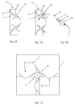
- figure 7 shows the first order lobed shape and the second order lobed shape of the trailing edge; in addition the dashed line shows the first order profile in the zone where the trailing edge has the second order lobed shape.
- the second order lobed shape can extend over the whole first order lobed shape ( figure 15 ) or only a part thereof ( figures 7, 9 , 11, 12 )
- the vortex generator 3 further has at least one or typically more nozzles 8 for fuel injection.
- the second order lobed shape 7 can be only provided in the vicinity of the nozzles 8. This way, the complexity and costs associated to manufacturing of the first and second order lobed shape 7 are limited to selected zones around the nozzles 8.
- the mixing is not affected by this configuration, because the fuel is injected from the nozzles 8 and is mixed with air or hot gas around the nozzles 8; therefore high turbulence around the nozzles 8 helps mixing whereas high turbulence at a small length scale (achievable via second order and possibly further order lobed shape) at zones apart from the nozzles 8 will be dissipated before it reaches the fuel and therefore only allows a limited contribution to the mixing.
- the second order lobed shape 7 can also be defined by a third order lobed shape 9; further order shapes are also possible. Also in this case the third and the possible further order lobed shapes of the trailing edge are preferably provided in the vicinity of the nozzles 8.
- An additional wall 10, also having a lobed shape, can be connected to the vortex generator 3.
- the additional wall 10 is preferably connected to the vortex generators 3 at the nozzles 8, i.e. at a position close to the nozzles 8; this way the turbulence generated by the additional walls 10 is around the nozzles 8, such that mixing of fuel with air/hot gas is increased.
- the additional wall 10 can be connected to the nozzles 8 and/or to a wall 11 between the leading edge 4 and trailing edge 5 of the vortex generator 3.
- the additional walls 10 can have the first order lobed shape ( figure 11 ) or the second order lobed shape ( figures 9, 10 ) or it can have the first order lobed shape in turn defined by a second order lobed shape ( figure 12 ). Further order lobed shapes are also possible ( figure 13 ) and the second, third and the possible further order lobed shapes of the trailing edge 5 are preferably provided at the nozzle 8.
- the additional wall 10 can have order lobed shapes different from the first and/or second and/or further order lobed shape.
- Figure 16 shows an embodiment with additional walls 10 having leading edge 10a extending from the leading edge 4. It is thus clear that the additional wall 10 can have the leading edge 10a extending from the leading edge 4 or from a position downstream of it.
- FIG 14 shows a rear view of an example of the burner 1.
- the burner 1 has four vortex generators 3 each with an elongated and streamline shape and with a leading edge 4 and a trailing edge 5.
- the vortex generators 3 have one end connected together at connection positions 14 and another end connected to the duct 2.
- any number of vortex generators 3 is possible, such as three or more than four vortex generators.
- connection positions 14 generate high turbulence around the connection positions 14, such that nozzles 8 can be advantageously provided at the connection positions 14.
- the nozzles can be provided over the wall 11 at a distance from the trailing edge 5.
- the nozzles 8 can be defined by one or more slots at the trailing edge 5 ( figure 3 ) and/or by one or more slots on the wall 11 ( figure 5 ) and/or by one or more injectors (such as round injectors) at the trailing edge 5 ( figure 4 ) and/or by one or more injectors (such as round injectors) on the wall 11 ( figure 6 ). Any combinations of slots and/or injectors at the trailing edge 5 and/or at on the wall 11 is possible.
- the nozzles 8 can have all the same position over the transversal axis T or they can have different positions over the transversal axis T; in this last case all combinations are possible, such that all nozzles 8 have different positions or the nozzles are divided in groups of nozzles wherein nozzles of the same group have the same position.
- vortex generators having an elongated and streamline shape
- these vortex generators are shown in the drawings with a straight longitudinal axis
- the vortex generators can have any shape and in particular they can have a curved shape defined by a curved longitudinal axis.
- the nozzles 8 are provided with a central passage for oil or other liquid or gas fuel and an annular passage for carrier air or other gas.
- the duct 2 has an inlet 2in and an outlet 2out.
- the burner 1 can be supplied with fresh air or with hot gas still containing oxygen and coming from a gas turbine upstream of the burner 1 or from a combustion chamber (for example a combustion chamber of the gas turbine also having the burner 1) upstream of the burner 1.
- a combustion chamber for example a combustion chamber of the gas turbine also having the burner 1.
- Hot gas G enters the inlet 2in and moves through the duct 2 and around the vortex generators 3, generating vortices.
- Fuel F is thus injected from the nozzles 8 into the vortices, such that hot gas G and fuel F are mixed, generating a mixture M that is combusted, typically in a combustion chamber downstream of the burner.
- the first order lobed shape 6 of the vortex generators 3 induces first order vortices V1 into the hot gas G, these first order vortices V1 generate mixing on a large scale; likewise the second order (and possibly further order) lobed shape of the vortex generators 3 induces second order (and possibly further order) vortices V2 into the hot gas G; these second order (and possibly further order) vortices V2 generate mixing on a smaller scale than the first order vortices V1, such that intimate mixing can be quickly achieved.
- second and possibly higher order lobed shape are provided close to the nozzles 8 and since higher order vortices (i.e. smaller vortices that are generated by the higher order lobed shape of the trailing edge 5 and/or additional wall 10 like the vortices V2) cause local mixing where the fuel is available (i.e. close to the nozzles 8), quick mixing is achieved.
- second and possibly higher order lobed shape are not provided at parts of the trailing edge 5 apart from the nozzles 8 because the small vortices (like the vortices V2) generated by them would cause no or limited mixing of the hot gas G with fuel F, because fuel F is not available or is available only to a limited extend apart from the nozzles 8.
- costs and complications to manufacture second and possibly further lobed order shape at parts of the trailing edge 5 apart from the nozzles 8 are saved.
- the additional walls 10 contribute to the mixing by increasing the vortices and possibly inducing vortices of an order different from the order of the vortices induced by the wall 11 (in case the additional walls 10 have lobed shapes of an order different from the order of the wall 11); this can further improve mixing.
- connection positions 14 can be advantageously used not only for obtaining large turbulence around the connection position 14, but also to have a structure able to compensate for thermal expansion of the materials.
- nozzles 8 located at different positions at the trailing edge 5 or upstream of the trailing edge 5 can be used to inject fuels having different reactivity.
Landscapes
- Engineering & Computer Science (AREA)
- Chemical & Material Sciences (AREA)
- Combustion & Propulsion (AREA)
- Mechanical Engineering (AREA)
- General Engineering & Computer Science (AREA)
- Gas Burners (AREA)
Priority Applications (5)
| Application Number | Priority Date | Filing Date | Title |
|---|---|---|---|
| EP14194930.5A EP3026344B1 (fr) | 2014-11-26 | 2014-11-26 | Brûleur d'une turbine à gaz |
| US14/950,759 US10215416B2 (en) | 2014-11-26 | 2015-11-24 | Burner of a gas turbine with a lobed shape vortex generator |
| KR1020150165595A KR20160063272A (ko) | 2014-11-26 | 2015-11-25 | 가스 터빈의 버너 |
| CN201510835317.1A CN105627369B (zh) | 2014-11-26 | 2015-11-26 | 燃气涡轮的焚烧器 |
| JP2015230523A JP2016105036A (ja) | 2014-11-26 | 2015-11-26 | ガスタービンのバーナ |
Applications Claiming Priority (1)
| Application Number | Priority Date | Filing Date | Title |
|---|---|---|---|
| EP14194930.5A EP3026344B1 (fr) | 2014-11-26 | 2014-11-26 | Brûleur d'une turbine à gaz |
Publications (2)
| Publication Number | Publication Date |
|---|---|
| EP3026344A1 true EP3026344A1 (fr) | 2016-06-01 |
| EP3026344B1 EP3026344B1 (fr) | 2019-05-22 |
Family
ID=51999276
Family Applications (1)
| Application Number | Title | Priority Date | Filing Date |
|---|---|---|---|
| EP14194930.5A Active EP3026344B1 (fr) | 2014-11-26 | 2014-11-26 | Brûleur d'une turbine à gaz |
Country Status (5)
| Country | Link |
|---|---|
| US (1) | US10215416B2 (fr) |
| EP (1) | EP3026344B1 (fr) |
| JP (1) | JP2016105036A (fr) |
| KR (1) | KR20160063272A (fr) |
| CN (1) | CN105627369B (fr) |
Families Citing this family (6)
| Publication number | Priority date | Publication date | Assignee | Title |
|---|---|---|---|---|
| EP2837883B1 (fr) * | 2013-08-16 | 2018-04-04 | Ansaldo Energia Switzerland AG | Chambre de combustion tubulaire pré-mélangée ayant des aubes ondulées pour le deuxième étage d'une turbine à gaz séquentielle |
| EP3354984B1 (fr) * | 2017-01-31 | 2020-09-09 | Ansaldo Energia Switzerland AG | Injecteur à lobes pour une chambre de combustion de turbine à gaz |
| US11242806B2 (en) * | 2017-11-20 | 2022-02-08 | Power Systems Mfg., Llc | Method of controlling fuel injection in a reheat combustor for a combustor unit of a gas turbine |
| FR3162501A1 (fr) * | 2024-05-24 | 2025-11-28 | Safran | Injecteur ondulé de dispositif d’injection pour chambre de combustion |
| FR3162832A1 (fr) * | 2024-05-31 | 2025-12-05 | Safran Aircraft Engines | Dispositif de tourbillonnement radial pour chambre de combustion de turbomachine. |
| US12535216B1 (en) * | 2025-01-02 | 2026-01-27 | General Electric Company | Combustion section for a turbine engine |
Citations (7)
| Publication number | Priority date | Publication date | Assignee | Title |
|---|---|---|---|---|
| EP1894616A1 (fr) * | 2006-08-30 | 2008-03-05 | Fachhochschule Zentralschweiz | Mélangeur statique |
| EP2211109A1 (fr) * | 2009-01-23 | 2010-07-28 | Alstom Technology Ltd | Brûleur de turbine à gaz et procédé pour mélanger un carburant avec un flux gazeux |
| WO2011054757A2 (fr) * | 2009-11-07 | 2011-05-12 | Alstom Technology Ltd | Système d'injection pour brûleur de réchauffage avec lances à combustible |
| WO2011054771A2 (fr) * | 2009-11-07 | 2011-05-12 | Alstom Technology Ltd | Brûleur à prémélange pour chambre de combustion de turbine à gaz |
| EP2496884A2 (fr) | 2009-11-07 | 2012-09-12 | ALSTOM Technology Ltd | Système d'injection de brûleur de postcombustion |
| US8528337B2 (en) | 2008-01-22 | 2013-09-10 | General Electric Company | Lobe nozzles for fuel and air injection |
| EP2644997A1 (fr) * | 2012-03-26 | 2013-10-02 | Alstom Technology Ltd | Agencement de mélange pour mélanger un combustible avec un flux de gaz contenant de l'oxygène |
Family Cites Families (11)
| Publication number | Priority date | Publication date | Assignee | Title |
|---|---|---|---|---|
| GB1253097A (fr) * | 1969-03-21 | 1971-11-10 | ||
| US3973395A (en) * | 1974-12-18 | 1976-08-10 | United Technologies Corporation | Low emission combustion chamber |
| US4830315A (en) * | 1986-04-30 | 1989-05-16 | United Technologies Corporation | Airfoil-shaped body |
| US5235813A (en) * | 1990-12-24 | 1993-08-17 | United Technologies Corporation | Mechanism for controlling the rate of mixing in combusting flows |
| US6655145B2 (en) * | 2001-12-20 | 2003-12-02 | Solar Turbings Inc | Fuel nozzle for a gas turbine engine |
| US6895756B2 (en) * | 2002-09-13 | 2005-05-24 | The Boeing Company | Compact swirl augmented afterburners for gas turbine engines |
| GB2437977A (en) * | 2006-05-12 | 2007-11-14 | Siemens Ag | A swirler for use in a burner of a gas turbine engine |
| EP1867925A1 (fr) * | 2006-06-12 | 2007-12-19 | Siemens Aktiengesellschaft | Brûleur |
| WO2011054739A2 (fr) * | 2009-11-07 | 2011-05-12 | Alstom Technology Ltd | Système d'injection pour brûleur de réchauffage |
| RU2550370C2 (ru) * | 2011-05-11 | 2015-05-10 | Альстом Текнолоджи Лтд | Центробежная форсунка с выступающими частями |
| US8938971B2 (en) * | 2011-05-11 | 2015-01-27 | Alstom Technology Ltd | Flow straightener and mixer |
-
2014
- 2014-11-26 EP EP14194930.5A patent/EP3026344B1/fr active Active
-
2015
- 2015-11-24 US US14/950,759 patent/US10215416B2/en active Active
- 2015-11-25 KR KR1020150165595A patent/KR20160063272A/ko not_active Withdrawn
- 2015-11-26 CN CN201510835317.1A patent/CN105627369B/zh active Active
- 2015-11-26 JP JP2015230523A patent/JP2016105036A/ja active Pending
Patent Citations (7)
| Publication number | Priority date | Publication date | Assignee | Title |
|---|---|---|---|---|
| EP1894616A1 (fr) * | 2006-08-30 | 2008-03-05 | Fachhochschule Zentralschweiz | Mélangeur statique |
| US8528337B2 (en) | 2008-01-22 | 2013-09-10 | General Electric Company | Lobe nozzles for fuel and air injection |
| EP2211109A1 (fr) * | 2009-01-23 | 2010-07-28 | Alstom Technology Ltd | Brûleur de turbine à gaz et procédé pour mélanger un carburant avec un flux gazeux |
| WO2011054757A2 (fr) * | 2009-11-07 | 2011-05-12 | Alstom Technology Ltd | Système d'injection pour brûleur de réchauffage avec lances à combustible |
| WO2011054771A2 (fr) * | 2009-11-07 | 2011-05-12 | Alstom Technology Ltd | Brûleur à prémélange pour chambre de combustion de turbine à gaz |
| EP2496884A2 (fr) | 2009-11-07 | 2012-09-12 | ALSTOM Technology Ltd | Système d'injection de brûleur de postcombustion |
| EP2644997A1 (fr) * | 2012-03-26 | 2013-10-02 | Alstom Technology Ltd | Agencement de mélange pour mélanger un combustible avec un flux de gaz contenant de l'oxygène |
Also Published As
| Publication number | Publication date |
|---|---|
| EP3026344B1 (fr) | 2019-05-22 |
| KR20160063272A (ko) | 2016-06-03 |
| JP2016105036A (ja) | 2016-06-09 |
| US10215416B2 (en) | 2019-02-26 |
| US20160146470A1 (en) | 2016-05-26 |
| CN105627369A (zh) | 2016-06-01 |
| CN105627369B (zh) | 2020-06-05 |
Similar Documents
| Publication | Publication Date | Title |
|---|---|---|
| EP3023696B1 (fr) | Lance à lobes pour chambre de combustion d'une turbine à gaz | |
| US10215416B2 (en) | Burner of a gas turbine with a lobed shape vortex generator | |
| JP5638613B2 (ja) | 燃焼装置用の入口予混合器 | |
| CN106164592B (zh) | 燃烧器、具有这种燃烧器的燃气轮机和燃料喷嘴 | |
| US8579214B2 (en) | Swirler vane | |
| EP2400216A1 (fr) | Lance de brûleur post-combustion | |
| US10920986B2 (en) | Gas turbine combustor base plate configuration | |
| EP2211109A1 (fr) | Brûleur de turbine à gaz et procédé pour mélanger un carburant avec un flux gazeux | |
| US9194587B2 (en) | Gas turbine combustion chamber | |
| CN107525096B (zh) | 多管延迟贫喷射器 | |
| CN102818290A (zh) | 具有旋流叶片的燃料喷嘴 | |
| EP2933559A1 (fr) | Agencement de mélange de carburant et chambre de combustion avec un tel agencement | |
| EP3147569A1 (fr) | Générateur de vortex et système d'injection de carburant d'une turbine à gaz avec un tel générateur | |
| US9441837B2 (en) | Premix burner of the multi-cone type for a gas turbine | |
| US8950187B2 (en) | Premix burner of the multi-cone type for a gas turbine | |
| JP6417620B2 (ja) | 燃焼器、ガスタービン | |
| EP2420730B1 (fr) | Brûleur de post-combustion | |
| EP2685162A1 (fr) | Brûleur de prémélange du type multi-cônes destiné à une turbine à gaz et procédé de fonctionnement d'un tel brûleur | |
| CN120390864A (zh) | 氢气燃烧装置 |
Legal Events
| Date | Code | Title | Description |
|---|---|---|---|
| PUAI | Public reference made under article 153(3) epc to a published international application that has entered the european phase |
Free format text: ORIGINAL CODE: 0009012 |
|
| AK | Designated contracting states |
Kind code of ref document: A1 Designated state(s): AL AT BE BG CH CY CZ DE DK EE ES FI FR GB GR HR HU IE IS IT LI LT LU LV MC MK MT NL NO PL PT RO RS SE SI SK SM TR |
|
| AX | Request for extension of the european patent |
Extension state: BA ME |
|
| RAP1 | Party data changed (applicant data changed or rights of an application transferred) |
Owner name: GENERAL ELECTRIC TECHNOLOGY GMBH |
|
| STAA | Information on the status of an ep patent application or granted ep patent |
Free format text: STATUS: REQUEST FOR EXAMINATION WAS MADE |
|
| 17P | Request for examination filed |
Effective date: 20161125 |
|
| RBV | Designated contracting states (corrected) |
Designated state(s): AL AT BE BG CH CY CZ DE DK EE ES FI FR GB GR HR HU IE IS IT LI LT LU LV MC MK MT NL NO PL PT RO RS SE SI SK SM TR |
|
| RAP1 | Party data changed (applicant data changed or rights of an application transferred) |
Owner name: ANSALDO ENERGIA SWITZERLAND AG |
|
| STAA | Information on the status of an ep patent application or granted ep patent |
Free format text: STATUS: EXAMINATION IS IN PROGRESS |
|
| 17Q | First examination report despatched |
Effective date: 20180717 |
|
| GRAP | Despatch of communication of intention to grant a patent |
Free format text: ORIGINAL CODE: EPIDOSNIGR1 |
|
| STAA | Information on the status of an ep patent application or granted ep patent |
Free format text: STATUS: GRANT OF PATENT IS INTENDED |
|
| INTG | Intention to grant announced |
Effective date: 20181214 |
|
| GRAS | Grant fee paid |
Free format text: ORIGINAL CODE: EPIDOSNIGR3 |
|
| GRAA | (expected) grant |
Free format text: ORIGINAL CODE: 0009210 |
|
| STAA | Information on the status of an ep patent application or granted ep patent |
Free format text: STATUS: THE PATENT HAS BEEN GRANTED |
|
| AK | Designated contracting states |
Kind code of ref document: B1 Designated state(s): AL AT BE BG CH CY CZ DE DK EE ES FI FR GB GR HR HU IE IS IT LI LT LU LV MC MK MT NL NO PL PT RO RS SE SI SK SM TR |
|
| REG | Reference to a national code |
Ref country code: GB Ref legal event code: FG4D |
|
| REG | Reference to a national code |
Ref country code: CH Ref legal event code: EP |
|
| REG | Reference to a national code |
Ref country code: IE Ref legal event code: FG4D |
|
| REG | Reference to a national code |
Ref country code: AT Ref legal event code: REF Ref document number: 1136568 Country of ref document: AT Kind code of ref document: T Effective date: 20190615 |
|
| REG | Reference to a national code |
Ref country code: DE Ref legal event code: R096 Ref document number: 602014047137 Country of ref document: DE |
|
| REG | Reference to a national code |
Ref country code: NL Ref legal event code: MP Effective date: 20190522 |
|
| REG | Reference to a national code |
Ref country code: LT Ref legal event code: MG4D |
|
| PG25 | Lapsed in a contracting state [announced via postgrant information from national office to epo] |
Ref country code: NO Free format text: LAPSE BECAUSE OF FAILURE TO SUBMIT A TRANSLATION OF THE DESCRIPTION OR TO PAY THE FEE WITHIN THE PRESCRIBED TIME-LIMIT Effective date: 20190822 Ref country code: AL Free format text: LAPSE BECAUSE OF FAILURE TO SUBMIT A TRANSLATION OF THE DESCRIPTION OR TO PAY THE FEE WITHIN THE PRESCRIBED TIME-LIMIT Effective date: 20190522 Ref country code: FI Free format text: LAPSE BECAUSE OF FAILURE TO SUBMIT A TRANSLATION OF THE DESCRIPTION OR TO PAY THE FEE WITHIN THE PRESCRIBED TIME-LIMIT Effective date: 20190522 Ref country code: SE Free format text: LAPSE BECAUSE OF FAILURE TO SUBMIT A TRANSLATION OF THE DESCRIPTION OR TO PAY THE FEE WITHIN THE PRESCRIBED TIME-LIMIT Effective date: 20190522 Ref country code: PT Free format text: LAPSE BECAUSE OF FAILURE TO SUBMIT A TRANSLATION OF THE DESCRIPTION OR TO PAY THE FEE WITHIN THE PRESCRIBED TIME-LIMIT Effective date: 20190922 Ref country code: HR Free format text: LAPSE BECAUSE OF FAILURE TO SUBMIT A TRANSLATION OF THE DESCRIPTION OR TO PAY THE FEE WITHIN THE PRESCRIBED TIME-LIMIT Effective date: 20190522 Ref country code: NL Free format text: LAPSE BECAUSE OF FAILURE TO SUBMIT A TRANSLATION OF THE DESCRIPTION OR TO PAY THE FEE WITHIN THE PRESCRIBED TIME-LIMIT Effective date: 20190522 Ref country code: LT Free format text: LAPSE BECAUSE OF FAILURE TO SUBMIT A TRANSLATION OF THE DESCRIPTION OR TO PAY THE FEE WITHIN THE PRESCRIBED TIME-LIMIT Effective date: 20190522 Ref country code: ES Free format text: LAPSE BECAUSE OF FAILURE TO SUBMIT A TRANSLATION OF THE DESCRIPTION OR TO PAY THE FEE WITHIN THE PRESCRIBED TIME-LIMIT Effective date: 20190522 |
|
| PG25 | Lapsed in a contracting state [announced via postgrant information from national office to epo] |
Ref country code: BG Free format text: LAPSE BECAUSE OF FAILURE TO SUBMIT A TRANSLATION OF THE DESCRIPTION OR TO PAY THE FEE WITHIN THE PRESCRIBED TIME-LIMIT Effective date: 20190822 Ref country code: RS Free format text: LAPSE BECAUSE OF FAILURE TO SUBMIT A TRANSLATION OF THE DESCRIPTION OR TO PAY THE FEE WITHIN THE PRESCRIBED TIME-LIMIT Effective date: 20190522 Ref country code: LV Free format text: LAPSE BECAUSE OF FAILURE TO SUBMIT A TRANSLATION OF THE DESCRIPTION OR TO PAY THE FEE WITHIN THE PRESCRIBED TIME-LIMIT Effective date: 20190522 Ref country code: GR Free format text: LAPSE BECAUSE OF FAILURE TO SUBMIT A TRANSLATION OF THE DESCRIPTION OR TO PAY THE FEE WITHIN THE PRESCRIBED TIME-LIMIT Effective date: 20190823 |
|
| REG | Reference to a national code |
Ref country code: AT Ref legal event code: MK05 Ref document number: 1136568 Country of ref document: AT Kind code of ref document: T Effective date: 20190522 |
|
| PG25 | Lapsed in a contracting state [announced via postgrant information from national office to epo] |
Ref country code: RO Free format text: LAPSE BECAUSE OF FAILURE TO SUBMIT A TRANSLATION OF THE DESCRIPTION OR TO PAY THE FEE WITHIN THE PRESCRIBED TIME-LIMIT Effective date: 20190522 Ref country code: SK Free format text: LAPSE BECAUSE OF FAILURE TO SUBMIT A TRANSLATION OF THE DESCRIPTION OR TO PAY THE FEE WITHIN THE PRESCRIBED TIME-LIMIT Effective date: 20190522 Ref country code: CZ Free format text: LAPSE BECAUSE OF FAILURE TO SUBMIT A TRANSLATION OF THE DESCRIPTION OR TO PAY THE FEE WITHIN THE PRESCRIBED TIME-LIMIT Effective date: 20190522 Ref country code: EE Free format text: LAPSE BECAUSE OF FAILURE TO SUBMIT A TRANSLATION OF THE DESCRIPTION OR TO PAY THE FEE WITHIN THE PRESCRIBED TIME-LIMIT Effective date: 20190522 Ref country code: AT Free format text: LAPSE BECAUSE OF FAILURE TO SUBMIT A TRANSLATION OF THE DESCRIPTION OR TO PAY THE FEE WITHIN THE PRESCRIBED TIME-LIMIT Effective date: 20190522 Ref country code: DK Free format text: LAPSE BECAUSE OF FAILURE TO SUBMIT A TRANSLATION OF THE DESCRIPTION OR TO PAY THE FEE WITHIN THE PRESCRIBED TIME-LIMIT Effective date: 20190522 |
|
| REG | Reference to a national code |
Ref country code: DE Ref legal event code: R097 Ref document number: 602014047137 Country of ref document: DE |
|
| PG25 | Lapsed in a contracting state [announced via postgrant information from national office to epo] |
Ref country code: IT Free format text: LAPSE BECAUSE OF FAILURE TO SUBMIT A TRANSLATION OF THE DESCRIPTION OR TO PAY THE FEE WITHIN THE PRESCRIBED TIME-LIMIT Effective date: 20190522 Ref country code: SM Free format text: LAPSE BECAUSE OF FAILURE TO SUBMIT A TRANSLATION OF THE DESCRIPTION OR TO PAY THE FEE WITHIN THE PRESCRIBED TIME-LIMIT Effective date: 20190522 |
|
| PLBE | No opposition filed within time limit |
Free format text: ORIGINAL CODE: 0009261 |
|
| STAA | Information on the status of an ep patent application or granted ep patent |
Free format text: STATUS: NO OPPOSITION FILED WITHIN TIME LIMIT |
|
| PG25 | Lapsed in a contracting state [announced via postgrant information from national office to epo] |
Ref country code: TR Free format text: LAPSE BECAUSE OF FAILURE TO SUBMIT A TRANSLATION OF THE DESCRIPTION OR TO PAY THE FEE WITHIN THE PRESCRIBED TIME-LIMIT Effective date: 20190522 |
|
| 26N | No opposition filed |
Effective date: 20200225 |
|
| PG25 | Lapsed in a contracting state [announced via postgrant information from national office to epo] |
Ref country code: PL Free format text: LAPSE BECAUSE OF FAILURE TO SUBMIT A TRANSLATION OF THE DESCRIPTION OR TO PAY THE FEE WITHIN THE PRESCRIBED TIME-LIMIT Effective date: 20190522 |
|
| PG25 | Lapsed in a contracting state [announced via postgrant information from national office to epo] |
Ref country code: SI Free format text: LAPSE BECAUSE OF FAILURE TO SUBMIT A TRANSLATION OF THE DESCRIPTION OR TO PAY THE FEE WITHIN THE PRESCRIBED TIME-LIMIT Effective date: 20190522 |
|
| REG | Reference to a national code |
Ref country code: CH Ref legal event code: PL |
|
| PG25 | Lapsed in a contracting state [announced via postgrant information from national office to epo] |
Ref country code: LI Free format text: LAPSE BECAUSE OF NON-PAYMENT OF DUE FEES Effective date: 20191130 Ref country code: CH Free format text: LAPSE BECAUSE OF NON-PAYMENT OF DUE FEES Effective date: 20191130 Ref country code: LU Free format text: LAPSE BECAUSE OF NON-PAYMENT OF DUE FEES Effective date: 20191126 Ref country code: MC Free format text: LAPSE BECAUSE OF FAILURE TO SUBMIT A TRANSLATION OF THE DESCRIPTION OR TO PAY THE FEE WITHIN THE PRESCRIBED TIME-LIMIT Effective date: 20190522 |
|
| REG | Reference to a national code |
Ref country code: BE Ref legal event code: MM Effective date: 20191130 |
|
| GBPC | Gb: european patent ceased through non-payment of renewal fee |
Effective date: 20191126 |
|
| PG25 | Lapsed in a contracting state [announced via postgrant information from national office to epo] |
Ref country code: GB Free format text: LAPSE BECAUSE OF NON-PAYMENT OF DUE FEES Effective date: 20191126 Ref country code: IE Free format text: LAPSE BECAUSE OF NON-PAYMENT OF DUE FEES Effective date: 20191126 Ref country code: FR Free format text: LAPSE BECAUSE OF NON-PAYMENT OF DUE FEES Effective date: 20191130 |
|
| PG25 | Lapsed in a contracting state [announced via postgrant information from national office to epo] |
Ref country code: BE Free format text: LAPSE BECAUSE OF NON-PAYMENT OF DUE FEES Effective date: 20191130 |
|
| PG25 | Lapsed in a contracting state [announced via postgrant information from national office to epo] |
Ref country code: CY Free format text: LAPSE BECAUSE OF FAILURE TO SUBMIT A TRANSLATION OF THE DESCRIPTION OR TO PAY THE FEE WITHIN THE PRESCRIBED TIME-LIMIT Effective date: 20190522 |
|
| PG25 | Lapsed in a contracting state [announced via postgrant information from national office to epo] |
Ref country code: IS Free format text: LAPSE BECAUSE OF FAILURE TO SUBMIT A TRANSLATION OF THE DESCRIPTION OR TO PAY THE FEE WITHIN THE PRESCRIBED TIME-LIMIT Effective date: 20190922 |
|
| PG25 | Lapsed in a contracting state [announced via postgrant information from national office to epo] |
Ref country code: MT Free format text: LAPSE BECAUSE OF FAILURE TO SUBMIT A TRANSLATION OF THE DESCRIPTION OR TO PAY THE FEE WITHIN THE PRESCRIBED TIME-LIMIT Effective date: 20190522 Ref country code: HU Free format text: LAPSE BECAUSE OF FAILURE TO SUBMIT A TRANSLATION OF THE DESCRIPTION OR TO PAY THE FEE WITHIN THE PRESCRIBED TIME-LIMIT; INVALID AB INITIO Effective date: 20141126 |
|
| PG25 | Lapsed in a contracting state [announced via postgrant information from national office to epo] |
Ref country code: MK Free format text: LAPSE BECAUSE OF FAILURE TO SUBMIT A TRANSLATION OF THE DESCRIPTION OR TO PAY THE FEE WITHIN THE PRESCRIBED TIME-LIMIT Effective date: 20190522 |
|
| P01 | Opt-out of the competence of the unified patent court (upc) registered |
Effective date: 20240430 |
|
| PGFP | Annual fee paid to national office [announced via postgrant information from national office to epo] |
Ref country code: DE Payment date: 20251118 Year of fee payment: 12 |