EP3026768A1 - Élément d'espacement phase-terre anti-ratés - Google Patents
Élément d'espacement phase-terre anti-ratés Download PDFInfo
- Publication number
- EP3026768A1 EP3026768A1 EP13889866.3A EP13889866A EP3026768A1 EP 3026768 A1 EP3026768 A1 EP 3026768A1 EP 13889866 A EP13889866 A EP 13889866A EP 3026768 A1 EP3026768 A1 EP 3026768A1
- Authority
- EP
- European Patent Office
- Prior art keywords
- spacer
- spacer body
- ground
- phase
- galloping
- Prior art date
- Legal status (The legal status is an assumption and is not a legal conclusion. Google has not performed a legal analysis and makes no representation as to the accuracy of the status listed.)
- Granted
Links
Images


Classifications
-
- H—ELECTRICITY
- H02—GENERATION; CONVERSION OR DISTRIBUTION OF ELECTRIC POWER
- H02G—INSTALLATION OF ELECTRIC CABLES OR LINES, OR OF COMBINED OPTICAL AND ELECTRIC CABLES OR LINES
- H02G7/00—Overhead installations of electric lines or cables
- H02G7/14—Arrangements or devices for damping mechanical oscillations of lines, e.g. for reducing production of sound
-
- H—ELECTRICITY
- H02—GENERATION; CONVERSION OR DISTRIBUTION OF ELECTRIC POWER
- H02G—INSTALLATION OF ELECTRIC CABLES OR LINES, OR OF COMBINED OPTICAL AND ELECTRIC CABLES OR LINES
- H02G7/00—Overhead installations of electric lines or cables
- H02G7/12—Devices for maintaining distance between parallel conductors, e.g. spacer
- H02G7/125—Damping spacers
Definitions
- the present invention relates to the field of anti-galloping devices, and specifically to a spacer.
- Galloping mainly acts on wires by wind, as a result, the distance between adjacent wires may be less than the minimum safe insulation distance at an operating voltage to cause an air insulation breakdown, leading to a power supply accident.
- a common practice is to dispose a phase-to-phase spacer between adjacent wires, and connect galloping two-phase wires by using the phase-phase spacer, where the wires restrict each other when galloping, to limit their respective galloping amplitude, and ensure a phase-to-phase insulation distance to prevent line mixing, and the phase-to-phase spacer can play a role of preventing line mixing.
- a phase-to-phase spacer is mainly used to suppress asynchronous galloping of adjacent two-phase wires, so that the two wires gradually move synchronously, so as to reduce the galloping amplitude. Years of operating experience also indicates that the phase-to-phase spacer indeed plays a role in managing galloping.
- phase-to-phase spacer used currently cannot effectively suppress synchronous galloping of two adjacent wires because the phase-to-phase spacer has the following obvious defects:
- An object of the present invention is to provide an anti-galloping phase-to-ground spacer, which can effectively improve suppression effects of synchronous galloping and asynchronous galloping of transmission lines, and significantly improve force conditions of the spacer and a fitting.
- the spacer body is a rigid spacer body, the rigid spacer body is formed by an inside epoxy resin glass drawing rod and an outside silicone rubber composite material layer; and the insulation umbrella skirt and the silicone rubber composite material layer are of a one-piece structure.
- the spacer body is a flexible spacer body, and the flexible spacer body comprises a spacer core and a silicone rubber composite material layer, the silicone rubber composite material layer is located on an outer layer of the spacer core, and the spacer core is made of a high-strength force-bearing nylon material.
- the spacer body is an adjustable spacer, the adjustable spacer comprises an upper spacer body, a lower spacer body, and a middle rod connected between the upper spacer body and the lower spacer body.
- An upper end of the upper spacer body is connected to the connecting fitting, a lower end of the lower spacer body is connected to the adjusting plate, outer circumferences of both the upper spacer body and the lower spacer body are connected to the insulation umbrella skirt, an upper side of the insulation umbrella skirt of the upper spacer body is connected to an end-portion accessory, and a lower side of the insulation umbrella skirt of the lower spacer body is also connected to an end-portion accessory; both a lower end of the upper spacer body and an upper end of the lower spacer body are connected to an end-portion accessory, and the two ends of the span wire are separately connected to the adjusting plate and the ground.
- Both the upper spacer body and the lower spacer body are formed by an inside epoxy resin glass reinforced plastic drawing rod and an outside silicone rubber composite material layer; and the insulation umbrella skirt and the silicone rubber composite material layer are of a one-piece structure.
- the number of the middle rod is one or more.
- the middle rod is movably connected to the upper spacer body and the lower spacer body.
- the middle rod is connected to the upper spacer body and the lower spacer body by a fixing ring.
- the spacer body between the lower end-portion accessory and the adjusting plate is further provided with an anti-snake device.
- the anti-snake device comprises a sphere with a smooth surface, the sphere is provided with a through hole, a gap is provided between the through hole and the rigid spacer body, and upper and lower sides of the sphere are provided with limiting sleeves for fixing the position of the sphere.
- the spacer comprises a sub-spacer whose two ends are connected to wires, wherein the connecting fitting is connected to the sub-spacer.
- the connecting fitting is a high-voltage end fitting.
- the end-portion accessories are grading rings.
- a sectional combined phase-to-ground spacer in the present invention while effectively improving management effects of synchronous galloping and asynchronous galloping of transmission lines, has good insulating effects and an adjustable length, and has the following advantages:
- the present invention is applied to a high-voltage transmission line within a range of 110 kV to 1000 kV.
- the present invention mainly comprises a spacer body 3, an adjusting plate 6, and a span wire 7.
- the rigid spacer body 3 is formed by an inside core made of glass fiber reinforced epoxy resin and an outside silicone rubber composite material layer.
- the insulation umbrella skirt 4 and the silicone rubber composite material layer are of a one-piece structure.
- An upper end and a lower end of the rigid spacer body 3 are respectively connected to a high-voltage end fitting 1 (connecting fitting) and the adjusting plate 6, and the high-voltage end fitting 1 is used to connect a sub-spacer 9.
- the rigid spacer body 3 between the high-voltage end fitting 1 and the adjusting plate 6 is sleeved with two end-portion accessories: an upper grading ring 2 and a lower grading ring 13, and the insulation umbrella skirt 4 is located between the upper grading ring 2 and the lower grading ring 13.
- a lower end of the adjusting plate 6 is connected to the span wire 7, and a lower end of the span wire 7 is connected to the ground 8.
- the rigid spacer body 3 between the lower grading ring 13 and the adjusting plate 6 is further provided with an anti-snake device 5.
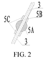
- the anti-snake device 5 comprises a sphere 5A with a smooth surface, the sphere 5A is provided with a through hole 5B, a gap is provided between the through hole 5B and the rigid spacer body 3, to facilitate penetration.
- the upper and lower sides of the sphere 5A are provided with limiting sleeves 5C for fixing the position of the sphere 5A.
- the lower end of the adjusting plate 6 is connected to the span wire 7, and the span wire 7 is fixed onto the ground 8 by using a ground anchor 11.
- the adjusting plate 6 can adjust the length of the span wire 7, thereby changing and adjusting a distance to the ground in the present invention.
- Both the span wire 7 and the adjusting plate 6 are made of special high-strength anti-theft materials.
- the present invention describes an installation manner of the phase-to-ground spacer by using a twin-bundled single-phase wire as an example (for installation manners of a quad-bundled wire, a hexa-bundled wire, an octant-bundled wire and other bundled wires, reference may be made to this embodiment).
- the high-voltage end fitting 1 is connected to the sub-spacer 9 of a wire 10, and the span wire 7 is fixed onto the ground by using the ground anchor 11.
- a phase-to-ground connection manner is used, which can suppress synchronous galloping of two-phase wires and can also suppress asynchronous galloping.
- a land protection pile 12 (a concrete pile) is added, and yellow warning lines are marked on the land protection pile 12, as marks, to prevent damage to the span wire 7 during farming.
- Embodiment 2 is the same as that of Embodiment 1, and Embodiment 2 is different from Embodiment 1 in that, the spacer body in this embodiment is a flexible spacer body 3, which comprises a spacer core and a silicone rubber composite material layer, the spacer core is made of a high-strength force-bearing nylon material, and the silicone rubber composite material layer is located on an outer layer of the spacer core.
- the spacer body in this embodiment is a flexible spacer body 3, which comprises a spacer core and a silicone rubber composite material layer, the spacer core is made of a high-strength force-bearing nylon material, and the silicone rubber composite material layer is located on an outer layer of the spacer core.
- An upper end and a lower end of the flexible spacer body 3 are respectively connected to the connecting fitting and the adjusting plate 6, the connecting fittings is the high-voltage end fitting 1, and the high-voltage end fitting 1 is used to connect the sub-spacer 9.
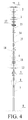
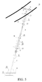
- Embodiment 3 is different from Embodiment 1 in that, as shown in Fig. 4 and Fig. 5 , the spacer body in the present invention is an adjustable spacer (that is, a sectional combined phase-to-ground spacer), and comprises upper and lower spacers: an upper spacer body 3 and a lower spacer body 16, the two spacer bodies are both formed by an inside epoxy resin glass reinforced plastic drawing rod and an outside silicone rubber composite material layer, the insulation umbrella skirt 4 is located on outer sides of the upper spacer body 3 and the lower spacer body 16, and the insulation umbrella skirt 4 and the silicone rubber composite material layer are of a one-piece structure, and are formed integrally.
- the spacer body in the present invention is an adjustable spacer (that is, a sectional combined phase-to-ground spacer), and comprises upper and lower spacers: an upper spacer body 3 and a lower spacer body 16, the two spacer bodies are both formed by an inside epoxy resin glass reinforced plastic drawing rod and an outside silicone rubber composite material layer, the insulation umbrella skirt 4 is located on outer sides
- a middle rod 14 is disposed between the upper spacer body 3 and the lower spacer body 16. Two ends of the middle rod 14 are separately provided with a connecting structure matching a connecting fitting on an end portion of a lower end of the upper spacer body 3 and a connecting structure matching a connecting fitting on an end portion of an upper end of the lower spacer body 16, and a moveable connection manner is used.
- a connecting member used in the connecting structure is a fixing ring 15, and the fixing ring 15 performs a sectional connection of the two spacers.
- middle rods 14 are connected end to end, the middle rods 14 are also connected by using the fixing ring 15, and are moveably connected, and the middle rods 14 are made of the same material as that of the upper spacer body 3 and the lower spacer body 16.
- the uppermost end and the lowest end of the connected middle rods 14 are respectively connected to the end portion of the lower end of the upper spacer body 3 and the end portion of the upper end of the lower spacer body 16.
- An upper end of the upper spacer body 3 is connected to the connecting fitting, the connecting fitting is the high-voltage end fitting 1, the high-voltage end fitting 1 is used to connect the sub-spacer 9, and a lower end of the lower spacer body 16 is connected to the adjusting plate 6.
- the upper end of the upper spacer body 3 is further sleeved with an end-portion accessory: the upper grading ring 2, and the lower end of the upper spacer body 3 is provided with an end-portion accessory: a small upper grading ring 17; the upper end of the lower spacer body 16 is provided with an end-portion accessory: a small lower grading ring 18, and a lower side of the lower spacer body 16 is sleeved with an end-portion accessory: the lower grading ring 13.
- the lower end of the adjusting plate 6 is connected to the span wire 7, and the lower end of the span wire 7 is connected to the ground 8.
- the lower spacer body 16 between the lower grading ring 13 and the adjusting plate 6 is further provided with the anti-snake device 5.
- the structure of the anti-snake device 5 is the same as that in Embodiment 1, and the installation manner is also the same as that in Embodiment 1.
- a spacer formed by a rigid spacer body is referred to as a rigid phase-to-ground spacer; a spacer formed by a flexible spacer body is referred to as a flexible phase-to-ground spacer; and a spacer formed by an adjustable spacer body is referred to as a sectional combined phase-to-ground spacer.
Landscapes
- Suspension Of Electric Lines Or Cables (AREA)
Applications Claiming Priority (4)
| Application Number | Priority Date | Filing Date | Title |
|---|---|---|---|
| CN201310310300.5A CN103414135B (zh) | 2013-07-23 | 2013-07-23 | 一种防舞动刚性相地间隔棒 |
| CN201310310480.7A CN103441462B (zh) | 2013-07-23 | 2013-07-23 | 分节组合式防舞动复合相地间隔棒 |
| CN201310310227.1A CN103457220B (zh) | 2013-07-23 | 2013-07-23 | 一种防舞动柔性复合相地间隔棒 |
| PCT/CN2013/088050 WO2015010403A1 (fr) | 2013-07-23 | 2013-11-28 | Élément d'espacement phase-terre anti-ratés |
Publications (3)
| Publication Number | Publication Date |
|---|---|
| EP3026768A1 true EP3026768A1 (fr) | 2016-06-01 |
| EP3026768A4 EP3026768A4 (fr) | 2017-08-09 |
| EP3026768B1 EP3026768B1 (fr) | 2020-07-29 |
Family
ID=52392657
Family Applications (1)
| Application Number | Title | Priority Date | Filing Date |
|---|---|---|---|
| EP13889866.3A Active EP3026768B1 (fr) | 2013-07-23 | 2013-11-28 | Élément d'espacement phase-terre anti-ratés |
Country Status (2)
| Country | Link |
|---|---|
| EP (1) | EP3026768B1 (fr) |
| WO (1) | WO2015010403A1 (fr) |
Cited By (2)
| Publication number | Priority date | Publication date | Assignee | Title |
|---|---|---|---|---|
| CN106099813A (zh) * | 2016-06-24 | 2016-11-09 | 国网河南省电力公司电力科学研究院 | 一种特高压垂直布置输电线路综合防舞方法 |
| CN106129944A (zh) * | 2016-06-24 | 2016-11-16 | 国网河南省电力公司电力科学研究院 | 一种特高压水平布置输电线路防舞方法 |
Family Cites Families (12)
| Publication number | Priority date | Publication date | Assignee | Title |
|---|---|---|---|---|
| FR2643757B1 (fr) * | 1989-02-24 | 1991-06-07 | Cahors App Elec | Procede et outil pour poser depuis le sol un espaceur de conducteurs d'une ligne electrique aerienne, et espaceur s'y rapportant |
| US5700980A (en) * | 1995-05-18 | 1997-12-23 | Conductron Corporation | Aerial cable spacer |
| JP2000308246A (ja) * | 1999-02-15 | 2000-11-02 | Furukawa Electric Co Ltd:The | ギャロッピング防止装置 |
| JP2003224924A (ja) * | 2002-01-29 | 2003-08-08 | Kansai Electric Power Co Inc:The | 送電線用相間スペーサ |
| CN101931192A (zh) * | 2009-06-23 | 2010-12-29 | 江苏省电力公司仪征市供电公司 | 一种绝缘护线装置 |
| KR101103553B1 (ko) * | 2011-03-07 | 2012-01-06 | 대원전기 주식회사 | 간격유지용 절연 가이더를 이용한 배전선로의 무정전 바이패스 공법 |
| CN202262345U (zh) * | 2011-09-28 | 2012-06-06 | 吕海波 | 防蛇鼠器滚筒 |
| CN202772532U (zh) * | 2012-07-11 | 2013-03-06 | 广州市迈克林电力有限公司 | 地、导线能量释放棒及地、导线间隔棒 |
| CN203434573U (zh) * | 2013-07-23 | 2014-02-12 | 国家电网公司 | 分节组合式防舞动复合相地间隔棒 |
| CN203522087U (zh) * | 2013-07-23 | 2014-04-02 | 国家电网公司 | 一种防舞动刚性相地间隔棒 |
| CN203339620U (zh) * | 2013-07-23 | 2013-12-11 | 国家电网公司 | 一种防舞动柔性复合相地间隔棒 |
| CN103414135B (zh) * | 2013-07-23 | 2016-06-01 | 国家电网公司 | 一种防舞动刚性相地间隔棒 |
-
2013
- 2013-11-28 EP EP13889866.3A patent/EP3026768B1/fr active Active
- 2013-11-28 WO PCT/CN2013/088050 patent/WO2015010403A1/fr not_active Ceased
Non-Patent Citations (1)
| Title |
|---|
| See references of WO2015010403A1 * |
Cited By (4)
| Publication number | Priority date | Publication date | Assignee | Title |
|---|---|---|---|---|
| CN106099813A (zh) * | 2016-06-24 | 2016-11-09 | 国网河南省电力公司电力科学研究院 | 一种特高压垂直布置输电线路综合防舞方法 |
| CN106129944A (zh) * | 2016-06-24 | 2016-11-16 | 国网河南省电力公司电力科学研究院 | 一种特高压水平布置输电线路防舞方法 |
| CN106099813B (zh) * | 2016-06-24 | 2017-09-08 | 国网河南省电力公司电力科学研究院 | 一种特高压垂直布置输电线路综合防舞方法 |
| CN106129944B (zh) * | 2016-06-24 | 2017-11-28 | 国网河南省电力公司电力科学研究院 | 一种特高压水平布置输电线路防舞方法 |
Also Published As
| Publication number | Publication date |
|---|---|
| EP3026768B1 (fr) | 2020-07-29 |
| WO2015010403A1 (fr) | 2015-01-29 |
| EP3026768A4 (fr) | 2017-08-09 |
Similar Documents
| Publication | Publication Date | Title |
|---|---|---|
| CN103441462B (zh) | 分节组合式防舞动复合相地间隔棒 | |
| ES2967100T3 (es) | Línea aérea de distribución de energía eléctrica | |
| KR101707758B1 (ko) | 파워 그리드의 송전선을 위한 합성의 탑 및 그의 합성의 크로스 암 구조물 | |
| US9633766B2 (en) | Energy efficient conductors with reduced thermal knee points and the method of manufacture thereof | |
| CN107093881B (zh) | 一种用于抑制输电线路绝缘子风偏的阻尼装置 | |
| US10886036B2 (en) | Energy efficient conductors with reduced thermal knee points and the method of manufacture thereof | |
| EP3026768B1 (fr) | Élément d'espacement phase-terre anti-ratés | |
| CN103414135B (zh) | 一种防舞动刚性相地间隔棒 | |
| CN203339620U (zh) | 一种防舞动柔性复合相地间隔棒 | |
| CN203536908U (zh) | 分节组合式防风偏复合绝缘拉索 | |
| US3291899A (en) | Electric insulators in the form of framed structures incorporating rods of resin bonded fibre | |
| CN203434573U (zh) | 分节组合式防舞动复合相地间隔棒 | |
| CN104895390B (zh) | 一种直线塔 | |
| Florea et al. | Upgrading the Romanian 400 kV lines with 2 and 3 subconductors per phase to reduce the risk of galloping occurance and the galloping amplitudes by the installation of torsional dampers and detuners, live-line procedures | |
| CN203522087U (zh) | 一种防舞动刚性相地间隔棒 | |
| CN103606873B (zh) | 分节组合式防风偏复合绝缘拉索及安装方法 | |
| CN103457220B (zh) | 一种防舞动柔性复合相地间隔棒 | |
| CN214273121U (zh) | 拉线塔 | |
| DE102016223791A1 (de) | Vogelschutz und Befestigungspunkt für eine Freileitung | |
| EP3857660B1 (fr) | Module de gestion de la foudre pour câble structurel et procédé et câble structurel correspondants | |
| CN100483879C (zh) | 输电线路阻尼式防绕击避雷针 | |
| CN104104047B (zh) | 一种支撑式防风偏装置 | |
| KR102422477B1 (ko) | 가공 송전선로를 고정하는 철탑 장치 및 그 시공방법 | |
| RU2773506C1 (ru) | Устройство изолирующей траверсы на опоре действующей воздушной линии электропередачи и способ устранения негабарита в пролете опор действующей воздушной линии электропередачи | |
| RU2748186C1 (ru) | Устройство для защиты воздушных линий электропередачи 6-35 кВ, защиты птиц от поражения электрическим током |
Legal Events
| Date | Code | Title | Description |
|---|---|---|---|
| PUAI | Public reference made under article 153(3) epc to a published international application that has entered the european phase |
Free format text: ORIGINAL CODE: 0009012 |
|
| 17P | Request for examination filed |
Effective date: 20150615 |
|
| AK | Designated contracting states |
Kind code of ref document: A1 Designated state(s): AL AT BE BG CH CY CZ DE DK EE ES FI FR GB GR HR HU IE IS IT LI LT LU LV MC MK MT NL NO PL PT RO RS SE SI SK SM TR |
|
| AX | Request for extension of the european patent |
Extension state: BA ME |
|
| DAX | Request for extension of the european patent (deleted) | ||
| A4 | Supplementary search report drawn up and despatched |
Effective date: 20170707 |
|
| RIC1 | Information provided on ipc code assigned before grant |
Ipc: H02G 7/14 20060101ALI20170704BHEP Ipc: H02G 7/12 20060101AFI20170704BHEP |
|
| STAA | Information on the status of an ep patent application or granted ep patent |
Free format text: STATUS: EXAMINATION IS IN PROGRESS |
|
| 17Q | First examination report despatched |
Effective date: 20180608 |
|
| GRAP | Despatch of communication of intention to grant a patent |
Free format text: ORIGINAL CODE: EPIDOSNIGR1 |
|
| STAA | Information on the status of an ep patent application or granted ep patent |
Free format text: STATUS: GRANT OF PATENT IS INTENDED |
|
| INTG | Intention to grant announced |
Effective date: 20200218 |
|
| RAP1 | Party data changed (applicant data changed or rights of an application transferred) |
Owner name: STATE GRID CORPORATION OF CHINA Owner name: STATE GRID HENAN ELECTRIC POWER CORPORATION ELECTRIC POWER SCIENCE RESEARCH INSTITUTE |
|
| GRAS | Grant fee paid |
Free format text: ORIGINAL CODE: EPIDOSNIGR3 |
|
| GRAA | (expected) grant |
Free format text: ORIGINAL CODE: 0009210 |
|
| STAA | Information on the status of an ep patent application or granted ep patent |
Free format text: STATUS: THE PATENT HAS BEEN GRANTED |
|
| AK | Designated contracting states |
Kind code of ref document: B1 Designated state(s): AL AT BE BG CH CY CZ DE DK EE ES FI FR GB GR HR HU IE IS IT LI LT LU LV MC MK MT NL NO PL PT RO RS SE SI SK SM TR |
|
| REG | Reference to a national code |
Ref country code: CH Ref legal event code: EP |
|
| REG | Reference to a national code |
Ref country code: AT Ref legal event code: REF Ref document number: 1296913 Country of ref document: AT Kind code of ref document: T Effective date: 20200815 |
|
| REG | Reference to a national code |
Ref country code: IE Ref legal event code: FG4D |
|
| REG | Reference to a national code |
Ref country code: DE Ref legal event code: R096 Ref document number: 602013071216 Country of ref document: DE |
|
| REG | Reference to a national code |
Ref country code: LT Ref legal event code: MG4D |
|
| REG | Reference to a national code |
Ref country code: NL Ref legal event code: MP Effective date: 20200729 |
|
| REG | Reference to a national code |
Ref country code: AT Ref legal event code: MK05 Ref document number: 1296913 Country of ref document: AT Kind code of ref document: T Effective date: 20200729 |
|
| PG25 | Lapsed in a contracting state [announced via postgrant information from national office to epo] |
Ref country code: GR Free format text: LAPSE BECAUSE OF FAILURE TO SUBMIT A TRANSLATION OF THE DESCRIPTION OR TO PAY THE FEE WITHIN THE PRESCRIBED TIME-LIMIT Effective date: 20201030 Ref country code: FI Free format text: LAPSE BECAUSE OF FAILURE TO SUBMIT A TRANSLATION OF THE DESCRIPTION OR TO PAY THE FEE WITHIN THE PRESCRIBED TIME-LIMIT Effective date: 20200729 Ref country code: PT Free format text: LAPSE BECAUSE OF FAILURE TO SUBMIT A TRANSLATION OF THE DESCRIPTION OR TO PAY THE FEE WITHIN THE PRESCRIBED TIME-LIMIT Effective date: 20201130 Ref country code: AT Free format text: LAPSE BECAUSE OF FAILURE TO SUBMIT A TRANSLATION OF THE DESCRIPTION OR TO PAY THE FEE WITHIN THE PRESCRIBED TIME-LIMIT Effective date: 20200729 Ref country code: NO Free format text: LAPSE BECAUSE OF FAILURE TO SUBMIT A TRANSLATION OF THE DESCRIPTION OR TO PAY THE FEE WITHIN THE PRESCRIBED TIME-LIMIT Effective date: 20201029 Ref country code: ES Free format text: LAPSE BECAUSE OF FAILURE TO SUBMIT A TRANSLATION OF THE DESCRIPTION OR TO PAY THE FEE WITHIN THE PRESCRIBED TIME-LIMIT Effective date: 20200729 Ref country code: BG Free format text: LAPSE BECAUSE OF FAILURE TO SUBMIT A TRANSLATION OF THE DESCRIPTION OR TO PAY THE FEE WITHIN THE PRESCRIBED TIME-LIMIT Effective date: 20201029 Ref country code: SE Free format text: LAPSE BECAUSE OF FAILURE TO SUBMIT A TRANSLATION OF THE DESCRIPTION OR TO PAY THE FEE WITHIN THE PRESCRIBED TIME-LIMIT Effective date: 20200729 Ref country code: HR Free format text: LAPSE BECAUSE OF FAILURE TO SUBMIT A TRANSLATION OF THE DESCRIPTION OR TO PAY THE FEE WITHIN THE PRESCRIBED TIME-LIMIT Effective date: 20200729 Ref country code: LT Free format text: LAPSE BECAUSE OF FAILURE TO SUBMIT A TRANSLATION OF THE DESCRIPTION OR TO PAY THE FEE WITHIN THE PRESCRIBED TIME-LIMIT Effective date: 20200729 |
|
| PG25 | Lapsed in a contracting state [announced via postgrant information from national office to epo] |
Ref country code: PL Free format text: LAPSE BECAUSE OF FAILURE TO SUBMIT A TRANSLATION OF THE DESCRIPTION OR TO PAY THE FEE WITHIN THE PRESCRIBED TIME-LIMIT Effective date: 20200729 Ref country code: RS Free format text: LAPSE BECAUSE OF FAILURE TO SUBMIT A TRANSLATION OF THE DESCRIPTION OR TO PAY THE FEE WITHIN THE PRESCRIBED TIME-LIMIT Effective date: 20200729 Ref country code: LV Free format text: LAPSE BECAUSE OF FAILURE TO SUBMIT A TRANSLATION OF THE DESCRIPTION OR TO PAY THE FEE WITHIN THE PRESCRIBED TIME-LIMIT Effective date: 20200729 Ref country code: IS Free format text: LAPSE BECAUSE OF FAILURE TO SUBMIT A TRANSLATION OF THE DESCRIPTION OR TO PAY THE FEE WITHIN THE PRESCRIBED TIME-LIMIT Effective date: 20201129 |
|
| PG25 | Lapsed in a contracting state [announced via postgrant information from national office to epo] |
Ref country code: NL Free format text: LAPSE BECAUSE OF FAILURE TO SUBMIT A TRANSLATION OF THE DESCRIPTION OR TO PAY THE FEE WITHIN THE PRESCRIBED TIME-LIMIT Effective date: 20200729 |
|
| PG25 | Lapsed in a contracting state [announced via postgrant information from national office to epo] |
Ref country code: IT Free format text: LAPSE BECAUSE OF FAILURE TO SUBMIT A TRANSLATION OF THE DESCRIPTION OR TO PAY THE FEE WITHIN THE PRESCRIBED TIME-LIMIT Effective date: 20200729 Ref country code: CZ Free format text: LAPSE BECAUSE OF FAILURE TO SUBMIT A TRANSLATION OF THE DESCRIPTION OR TO PAY THE FEE WITHIN THE PRESCRIBED TIME-LIMIT Effective date: 20200729 Ref country code: EE Free format text: LAPSE BECAUSE OF FAILURE TO SUBMIT A TRANSLATION OF THE DESCRIPTION OR TO PAY THE FEE WITHIN THE PRESCRIBED TIME-LIMIT Effective date: 20200729 Ref country code: DK Free format text: LAPSE BECAUSE OF FAILURE TO SUBMIT A TRANSLATION OF THE DESCRIPTION OR TO PAY THE FEE WITHIN THE PRESCRIBED TIME-LIMIT Effective date: 20200729 Ref country code: RO Free format text: LAPSE BECAUSE OF FAILURE TO SUBMIT A TRANSLATION OF THE DESCRIPTION OR TO PAY THE FEE WITHIN THE PRESCRIBED TIME-LIMIT Effective date: 20200729 Ref country code: SM Free format text: LAPSE BECAUSE OF FAILURE TO SUBMIT A TRANSLATION OF THE DESCRIPTION OR TO PAY THE FEE WITHIN THE PRESCRIBED TIME-LIMIT Effective date: 20200729 |
|
| REG | Reference to a national code |
Ref country code: DE Ref legal event code: R097 Ref document number: 602013071216 Country of ref document: DE |
|
| PG25 | Lapsed in a contracting state [announced via postgrant information from national office to epo] |
Ref country code: AL Free format text: LAPSE BECAUSE OF FAILURE TO SUBMIT A TRANSLATION OF THE DESCRIPTION OR TO PAY THE FEE WITHIN THE PRESCRIBED TIME-LIMIT Effective date: 20200729 |
|
| REG | Reference to a national code |
Ref country code: DE Ref legal event code: R119 Ref document number: 602013071216 Country of ref document: DE |
|
| PLBE | No opposition filed within time limit |
Free format text: ORIGINAL CODE: 0009261 |
|
| STAA | Information on the status of an ep patent application or granted ep patent |
Free format text: STATUS: NO OPPOSITION FILED WITHIN TIME LIMIT |
|
| PG25 | Lapsed in a contracting state [announced via postgrant information from national office to epo] |
Ref country code: SK Free format text: LAPSE BECAUSE OF FAILURE TO SUBMIT A TRANSLATION OF THE DESCRIPTION OR TO PAY THE FEE WITHIN THE PRESCRIBED TIME-LIMIT Effective date: 20200729 Ref country code: MC Free format text: LAPSE BECAUSE OF FAILURE TO SUBMIT A TRANSLATION OF THE DESCRIPTION OR TO PAY THE FEE WITHIN THE PRESCRIBED TIME-LIMIT Effective date: 20200729 |
|
| REG | Reference to a national code |
Ref country code: CH Ref legal event code: PL |
|
| 26N | No opposition filed |
Effective date: 20210430 |
|
| GBPC | Gb: european patent ceased through non-payment of renewal fee |
Effective date: 20201128 |
|
| PG25 | Lapsed in a contracting state [announced via postgrant information from national office to epo] |
Ref country code: LU Free format text: LAPSE BECAUSE OF NON-PAYMENT OF DUE FEES Effective date: 20201128 |
|
| REG | Reference to a national code |
Ref country code: BE Ref legal event code: MM Effective date: 20201130 |
|
| PG25 | Lapsed in a contracting state [announced via postgrant information from national office to epo] |
Ref country code: CH Free format text: LAPSE BECAUSE OF NON-PAYMENT OF DUE FEES Effective date: 20201130 Ref country code: SI Free format text: LAPSE BECAUSE OF FAILURE TO SUBMIT A TRANSLATION OF THE DESCRIPTION OR TO PAY THE FEE WITHIN THE PRESCRIBED TIME-LIMIT Effective date: 20200729 Ref country code: LI Free format text: LAPSE BECAUSE OF NON-PAYMENT OF DUE FEES Effective date: 20201130 |
|
| PG25 | Lapsed in a contracting state [announced via postgrant information from national office to epo] |
Ref country code: IE Free format text: LAPSE BECAUSE OF NON-PAYMENT OF DUE FEES Effective date: 20201128 Ref country code: FR Free format text: LAPSE BECAUSE OF NON-PAYMENT OF DUE FEES Effective date: 20201130 |
|
| PG25 | Lapsed in a contracting state [announced via postgrant information from national office to epo] |
Ref country code: GB Free format text: LAPSE BECAUSE OF NON-PAYMENT OF DUE FEES Effective date: 20201128 Ref country code: DE Free format text: LAPSE BECAUSE OF NON-PAYMENT OF DUE FEES Effective date: 20210601 |
|
| PG25 | Lapsed in a contracting state [announced via postgrant information from national office to epo] |
Ref country code: IS Free format text: LAPSE BECAUSE OF FAILURE TO SUBMIT A TRANSLATION OF THE DESCRIPTION OR TO PAY THE FEE WITHIN THE PRESCRIBED TIME-LIMIT Effective date: 20201129 Ref country code: TR Free format text: LAPSE BECAUSE OF FAILURE TO SUBMIT A TRANSLATION OF THE DESCRIPTION OR TO PAY THE FEE WITHIN THE PRESCRIBED TIME-LIMIT Effective date: 20200729 Ref country code: MT Free format text: LAPSE BECAUSE OF FAILURE TO SUBMIT A TRANSLATION OF THE DESCRIPTION OR TO PAY THE FEE WITHIN THE PRESCRIBED TIME-LIMIT Effective date: 20200729 Ref country code: CY Free format text: LAPSE BECAUSE OF FAILURE TO SUBMIT A TRANSLATION OF THE DESCRIPTION OR TO PAY THE FEE WITHIN THE PRESCRIBED TIME-LIMIT Effective date: 20200729 |
|
| PG25 | Lapsed in a contracting state [announced via postgrant information from national office to epo] |
Ref country code: MK Free format text: LAPSE BECAUSE OF FAILURE TO SUBMIT A TRANSLATION OF THE DESCRIPTION OR TO PAY THE FEE WITHIN THE PRESCRIBED TIME-LIMIT Effective date: 20200729 |
|
| PG25 | Lapsed in a contracting state [announced via postgrant information from national office to epo] |
Ref country code: BE Free format text: LAPSE BECAUSE OF NON-PAYMENT OF DUE FEES Effective date: 20201130 |