EP3027140B1 - Dispositif pour distribution de matériau dentaire - Google Patents
Dispositif pour distribution de matériau dentaire Download PDFInfo
- Publication number
- EP3027140B1 EP3027140B1 EP14750109.2A EP14750109A EP3027140B1 EP 3027140 B1 EP3027140 B1 EP 3027140B1 EP 14750109 A EP14750109 A EP 14750109A EP 3027140 B1 EP3027140 B1 EP 3027140B1
- Authority
- EP
- European Patent Office
- Prior art keywords
- dispensing
- cap
- dental
- dental material
- cartridge
- Prior art date
- Legal status (The legal status is an assumption and is not a legal conclusion. Google has not performed a legal analysis and makes no representation as to the accuracy of the status listed.)
- Not-in-force
Links
- 239000005548 dental material Substances 0.000 title claims description 52
- 239000000463 material Substances 0.000 claims description 26
- 239000011350 dental composite resin Substances 0.000 claims description 21
- 239000000945 filler Substances 0.000 claims description 9
- 239000000178 monomer Substances 0.000 claims description 6
- 239000003999 initiator Substances 0.000 claims description 4
- 230000007704 transition Effects 0.000 claims description 3
- 230000000977 initiatory effect Effects 0.000 claims description 2
- 238000000926 separation method Methods 0.000 claims description 2
- 238000011049 filling Methods 0.000 description 14
- VYPSYNLAJGMNEJ-UHFFFAOYSA-N silicon dioxide Inorganic materials O=[Si]=O VYPSYNLAJGMNEJ-UHFFFAOYSA-N 0.000 description 8
- 239000003086 colorant Substances 0.000 description 4
- 239000000203 mixture Substances 0.000 description 4
- 230000005855 radiation Effects 0.000 description 4
- 235000012239 silicon dioxide Nutrition 0.000 description 4
- 239000000126 substance Substances 0.000 description 4
- -1 acryloxy" group Chemical group 0.000 description 3
- 238000006243 chemical reaction Methods 0.000 description 3
- OKTJSMMVPCPJKN-UHFFFAOYSA-N Carbon Chemical compound [C] OKTJSMMVPCPJKN-UHFFFAOYSA-N 0.000 description 2
- TZCXTZWJZNENPQ-UHFFFAOYSA-L barium sulfate Chemical compound [Ba+2].[O-]S([O-])(=O)=O TZCXTZWJZNENPQ-UHFFFAOYSA-L 0.000 description 2
- 239000002131 composite material Substances 0.000 description 2
- 238000011109 contamination Methods 0.000 description 2
- 239000011159 matrix material Substances 0.000 description 2
- 239000010453 quartz Substances 0.000 description 2
- 239000011347 resin Substances 0.000 description 2
- 229920005989 resin Polymers 0.000 description 2
- RMAQACBXLXPBSY-UHFFFAOYSA-N silicic acid Chemical compound O[Si](O)(O)O RMAQACBXLXPBSY-UHFFFAOYSA-N 0.000 description 2
- 239000011345 viscous material Substances 0.000 description 2
- IUVCFHHAEHNCFT-INIZCTEOSA-N 2-[(1s)-1-[4-amino-3-(3-fluoro-4-propan-2-yloxyphenyl)pyrazolo[3,4-d]pyrimidin-1-yl]ethyl]-6-fluoro-3-(3-fluorophenyl)chromen-4-one Chemical compound C1=C(F)C(OC(C)C)=CC=C1C(C1=C(N)N=CN=C11)=NN1[C@@H](C)C1=C(C=2C=C(F)C=CC=2)C(=O)C2=CC(F)=CC=C2O1 IUVCFHHAEHNCFT-INIZCTEOSA-N 0.000 description 1
- BAPJBEWLBFYGME-UHFFFAOYSA-N Methyl acrylate Chemical group COC(=O)C=C BAPJBEWLBFYGME-UHFFFAOYSA-N 0.000 description 1
- 229920004482 WACKER® Polymers 0.000 description 1
- NIXOWILDQLNWCW-UHFFFAOYSA-M acrylate group Chemical group C(C=C)(=O)[O-] NIXOWILDQLNWCW-UHFFFAOYSA-M 0.000 description 1
- 229910052782 aluminium Inorganic materials 0.000 description 1
- XAGFODPZIPBFFR-UHFFFAOYSA-N aluminium Chemical compound [Al] XAGFODPZIPBFFR-UHFFFAOYSA-N 0.000 description 1
- WUKWITHWXAAZEY-UHFFFAOYSA-L calcium difluoride Chemical compound [F-].[F-].[Ca+2] WUKWITHWXAAZEY-UHFFFAOYSA-L 0.000 description 1
- 229910001634 calcium fluoride Inorganic materials 0.000 description 1
- 239000000378 calcium silicate Substances 0.000 description 1
- 229910052918 calcium silicate Inorganic materials 0.000 description 1
- OYACROKNLOSFPA-UHFFFAOYSA-N calcium;dioxido(oxo)silane Chemical compound [Ca+2].[O-][Si]([O-])=O OYACROKNLOSFPA-UHFFFAOYSA-N 0.000 description 1
- CREMABGTGYGIQB-UHFFFAOYSA-N carbon carbon Chemical compound C.C CREMABGTGYGIQB-UHFFFAOYSA-N 0.000 description 1
- 239000011203 carbon fibre reinforced carbon Substances 0.000 description 1
- 239000003054 catalyst Substances 0.000 description 1
- 239000003795 chemical substances by application Substances 0.000 description 1
- 239000011248 coating agent Substances 0.000 description 1
- 238000000576 coating method Methods 0.000 description 1
- 238000004891 communication Methods 0.000 description 1
- 229910052906 cristobalite Inorganic materials 0.000 description 1
- 239000002978 dental impression material Substances 0.000 description 1
- 238000001035 drying Methods 0.000 description 1
- 238000001125 extrusion Methods 0.000 description 1
- 230000009969 flowable effect Effects 0.000 description 1
- 150000002222 fluorine compounds Chemical class 0.000 description 1
- 229910021485 fumed silica Inorganic materials 0.000 description 1
- 239000000499 gel Substances 0.000 description 1
- 239000008187 granular material Substances 0.000 description 1
- 239000005337 ground glass Substances 0.000 description 1
- 239000011346 highly viscous material Substances 0.000 description 1
- 230000002427 irreversible effect Effects 0.000 description 1
- 230000007246 mechanism Effects 0.000 description 1
- 229910052751 metal Inorganic materials 0.000 description 1
- 239000002184 metal Substances 0.000 description 1
- 125000005641 methacryl group Chemical group 0.000 description 1
- 238000000034 method Methods 0.000 description 1
- SNVLJLYUUXKWOJ-UHFFFAOYSA-N methylidenecarbene Chemical compound C=[C] SNVLJLYUUXKWOJ-UHFFFAOYSA-N 0.000 description 1
- 239000002808 molecular sieve Substances 0.000 description 1
- 230000000704 physical effect Effects 0.000 description 1
- 239000004033 plastic Substances 0.000 description 1
- 229920003023 plastic Polymers 0.000 description 1
- 238000006116 polymerization reaction Methods 0.000 description 1
- 230000002028 premature Effects 0.000 description 1
- 238000002360 preparation method Methods 0.000 description 1
- 230000001698 pyrogenic effect Effects 0.000 description 1
- 238000007789 sealing Methods 0.000 description 1
- 239000000377 silicon dioxide Substances 0.000 description 1
- URGAHOPLAPQHLN-UHFFFAOYSA-N sodium aluminosilicate Chemical compound [Na+].[Al+3].[O-][Si]([O-])=O.[O-][Si]([O-])=O URGAHOPLAPQHLN-UHFFFAOYSA-N 0.000 description 1
- 238000001228 spectrum Methods 0.000 description 1
- 125000000391 vinyl group Chemical group [H]C([*])=C([H])[H] 0.000 description 1
- 229940105963 yttrium fluoride Drugs 0.000 description 1
- RBORBHYCVONNJH-UHFFFAOYSA-K yttrium(iii) fluoride Chemical compound F[Y](F)F RBORBHYCVONNJH-UHFFFAOYSA-K 0.000 description 1
- 239000010457 zeolite Substances 0.000 description 1
- GFQYVLUOOAAOGM-UHFFFAOYSA-N zirconium(iv) silicate Chemical compound [Zr+4].[O-][Si]([O-])([O-])[O-] GFQYVLUOOAAOGM-UHFFFAOYSA-N 0.000 description 1
Images


Classifications
-
- A—HUMAN NECESSITIES
- A61—MEDICAL OR VETERINARY SCIENCE; HYGIENE
- A61C—DENTISTRY; APPARATUS OR METHODS FOR ORAL OR DENTAL HYGIENE
- A61C5/00—Filling or capping teeth
- A61C5/60—Devices specially adapted for pressing or mixing capping or filling materials, e.g. amalgam presses
- A61C5/62—Applicators, e.g. syringes or guns
-
- A—HUMAN NECESSITIES
- A61—MEDICAL OR VETERINARY SCIENCE; HYGIENE
- A61C—DENTISTRY; APPARATUS OR METHODS FOR ORAL OR DENTAL HYGIENE
- A61C1/00—Dental machines for boring or cutting ; General features of dental machines or apparatus, e.g. hand-piece design
- A61C1/08—Machine parts specially adapted for dentistry
- A61C1/16—Protecting caps for hand-pieces or angle-pieces
Definitions
- the invention relates to a device for dispensing a dental material, and in particular to a device which has a dispensing end and a cap which are rotatable relative to each other between an open position for dispensing and a closed position for storage of the dental material.
- Dental composite filling materials typically contain a predominant amount of fillers, for example quartz, and a relatively small amount of a flowable monomer. Such composites typically further contain a photo initiator allowing the monomer to be polymerized through light energy. Therefore the dental composite filling materials may be applied in a cavity in a patient's tooth and light-cured after application in the patient's tooth.
- a dispensing device for dispensing dental composite filling materials is for example disclosed in US 7,128,246 B2 .
- Such a device stores a portion of a dental composite filling material which can be extruded by displacing a piston within the device.
- the device can be coupled to a hand-held dispensing gun providing a relatively high force for displacing the piston via a hand operable leverage.
- WO 2006/108085 A2 discloses a syringe delivery system for dispensing a highly viscous material through a syringe delivery opening.
- the system includes a syringe barrel having a delivery opening, a plunger including a threaded shaft that threadably engages the syringe barrel for selectively dispensing a viscous material through the delivery opening, and a plunger gripping member in gripping communication with the plunger that includes means for sealing the threaded shaft of the plunger so as to prevent contamination by foreign matter.
- the syringe has a sheath that covers the threaded shaft of the plunger so as to hide the plunger beneath the sheath. The sheath provides a sealed environment for the threaded shaft so as to prevent entrance or contamination by foreign matter.
- WO 2013/016642 A2 discloses a device for dispensing a dental substance.
- the device comprises a cartridge for containing the dental substance.
- the cartridge has a plunger, and a dispensing opening. Further the device is operable to urge the dental substance toward the dispensing opening.
- the device further comprises a cutter for cutting off a portion of the dental substance which protrudes over the dispensing opening.
- dispensers for dental composite filling materials are available there is still a need for a dispenser which is easy to use, which accounts for hygiene requirements in dentistry and which helps maximizing shelf life of the dental material stored therein.
- the invention is as defined in claim 1.
- the invention relates to a device for dispensing a dental material, and in particular for dispensing a dental composite filling material.
- the device comprises a cartridge having a dispensing end which extends along a longitudinal axis.
- the dispensing end has or provides a dispensing opening for the dental material, and has in essence an axially symmetric shape about the longitudinal axis.
- the axially symmetric shape has a truncation.
- the truncation provides the dispensing end with a generally flat dispensing surface through which the dispensing opening extends.
- truncation as referred to in this specification is used to define the structural shape of the dispensing end.
- the truncation provides a structure that is asymmetric with respect to or within an otherwise overall axially symmetric shape.
- the term “truncation” however does not limit the invention to any structure - although it covers such structure - which is actually obtained by a truncation action, for example by cutting, but refers to the structure as such independent from the method by which that structure was obtained.
- the dispensing surface is oriented in a non-orthogonal relationship with the longitudinal axis.
- the three-dimensional shape of the dispensing surface may in at least one dimension be oriented at an inclination angle which non-parallel as well as different from 90 degrees relative to the longitudinal axis.
- the device further comprises a cap disposed over, or received on the dispensing end.
- the cap and the dispensing end are rotatable relative to each other about the longitudinal axis between an open position and a closed position. In the open position an orifice in the cap uncovers the dispensing surface, whereas in the closed position a closed space is formed between the cap and the dispensing surface. In the closed position the cap thus preferably seals the dispensing opening from the exterior of the device although the closed space is present between the cap and the dispensing surface.
- the invention is advantageous in that it provides a device which is relatively easy to use. Further the device preferably allows for dispensation of a portion of a dental material and for encapsulating that portion within the device from the exterior of the device. Further the device preferably allows for picking up one or more sub-portion of the dispensed portion and for keeping any remainder of the dispensed portion encapsulated in the device. Thus the device may help 7-Apr-2017 maximizing the time period over which the dental material can be used after dispensation from the cartridge. The device further helps metering a portion of dental material dispensed from the device and allows the dental material to be picked-up in a relative convenient manner.
- the dispensing surface is generally planar.
- the dispensing surface may be planar or exactly planar it has been found that a slight convex shape of the dispensing surface may allow for picking up a portion of dental material dispensed from the dispensing opening relatively conveniently by a dental instrument, for example a spatula. This is during manually cutting off the dental material adjacent the dispensing opening the dispensing surface may provide for guidance of the spatula and the curvature of the slight convex shape may allow slight skewing of the spatula as it may occur during such manual operation.
- the dispensing surface preferably entirely surrounds the dispensing opening. Thus the dispensing surface may allow for guiding the dental instrument relative reliable and precisely over the dispensing opening.
- the axially symmetric shape is generally cylindrical.
- the symmetric shape may particularly be formed by a generally cylindrical outer side face, a free front face and the dispensing surface.
- the dispensing surface preferably forms a first edge with the side face and a second edge with the front face.
- a conical shape may be used instead of a cylindrical shape as appropriate.
- the first and second edges may form a common continuous edge with one another.
- the front face of the dispensing end comprises a generally ball-shaped surface.
- the front face of the dispensing end may however alternatively be planar or generally planar.
- the front face of the dispensing end may further have a radius in the transition between the front face and the side face.
- the front face may be formed by a ball-shaped front wall which further has a ball-shaped inner face, optionally with a radius in the transition between the inner face and inner side faces. A so shaped front wall may help maximizing the resistance of the cartridge to pressure exerted to the front wall during dispensation of the dental material.
- the dispensing surface and the longitudinal axis are inclined with respect to each other in an angle of between about 30 degrees and 60 degrees.
- the dispensing surface may extend along essentially two dimensions, one of which is inclined with respect to the longitudinal axis in an angle of between about 30 degrees and 60 degrees, preferably in an angle of about 45 degrees. The angle thereby refers to the included angle between the dispensing surface and the longitudinal axis, measured within boundaries of the device.
- the cartridge has a substantially lightproof cartridge wall at least for visible light.
- visible light refers to light at wavelengths of between 380 nm (nanometers) and 750 nm.
- the cartridge may particularly have a lightproof or substantially lightproof cartridge wall for blue light which for the purpose of the present specification refers to light at wavelengths of between 450 nm and 495 nm.
- the cartridge may be adapted to block light which would be suitable to initiate hardening of a light-hardenable dental material.
- At least the dispensing end of the device may be formed by the lightproof cartridge wall.
- the cap may have a lightproof or substantially lightproof cap wall at least for visible light or in more particular for blue light.
- the cap may be adapted to block light which is suitable to initiate hardening of a light-hardenable dental material. Therefore the device is preferably overall adapted to prevent a light-hardenable dental material from exposure to light, and thus to prevent premature hardening of the dental material within the device.
- the cap and the cartridge are locked with one another against separation.
- the cap may have one or more retainer or an annular bulge at its lateral inner surface, and the dispensing end may have a corresponding groove for engaging with the retainer or bulge.
- the groove may be located behind the front most free end of the dispensing end.
- the cartridge forms a chamber for storing the dental material.
- the device further preferably comprises a plunger for extruding the dental material from the chamber.
- the device may comprise a threaded plunger.
- the device thus may be adapted such that the dental material is extrudable by rotation of the plunger.
- Such a threaded plunger may be advantageous for extruding a dental material having a high viscosity, because the threaded plunger typically converts a relatively low operation force (applied by a user) into a relatively high extrusion force. Further such a threaded plunger typically allows the dental material to be dispensed relatively accurately.
- the device in particular the cartridge, comprises or contains the dental material, and in particular a dental composite filling material.
- the dental composite filling material is preferably a light-hardenable dental composite filling material.
- the dental material may be a dental composite material comprising a predominant portion by weight of fillers, a hardenable monomer and a photo initiator adapted for initiating hardening of the monomer.
- Dental composite materials typically comprise a hardenable resin matrix comprising hardenable components, an initiator system suitable to harden the hardenable components contained in the resin matrix and filler(s).
- the filler content is typically above about 50, 60 or 70 wt.-% with respect to the weight of the dental composite material. Typical ranges include from about 50 to about 90 wt.-% or from about 60 to about 80 wt.-%.
- the hardenable components typically comprise unsaturated moieties (carbon-carbon unsaturation) like (meth)acrylate moieties. In order to be crosslinkable, the hardenable components typically comprise at least about 2 unsaturated moieties.
- the composite material may comprise only one type of filler or different types of fillers.
- suitable filler(s) include fumed silica, quartz, ground glasses, non-water-soluble fluorides such as CaF 2 , silica gels such as silicic acid, in particular pyrogenic silicic acid and granulates thereof, cristobalite, calcium silicate, zirconium silicate, zeolites, including the molecular sieves, barium sulphate and/or yttrium fluoride.
- Suitable fumed silicas include for example, products sold under the tradename AerosilTM series OX-50, -130, -150, and -200, Aerosil R8200 available from Degussa AG, (Hanau, Germany), CAB-O-SILTM M5 available from Cabot Corp (Tuscola, Ill.), and HDK types, e.g. HDK-H 2000, HDK H15; HDK H18, HDK H20 and HDK H30 available from Wacker.
- the average surface area of the silica particles is preferably greater than about 15 m 2 /g more preferably greater than about 30 m 2 /g.
- a “hardenable component or material” or “polymerizable component” is any component which can be cured or solidified e.g. by radiation-induced polymerization.
- a hardenable component may contain only one, two, three or more polymerizable groups.
- Typical examples of polymerizable groups include unsaturated carbon groups, such as a vinyl group being present i.a. in a (methyl)acrylate group.
- (Meth)acryl is a shorthand term referring to "acryl” and/or "methacryl".
- a “curing, hardening or setting reaction” is used interchangeable and refers to a reaction wherein physical properties such as viscosity and hardness of a composition changes over the time due to a chemical reaction between the individual components.
- Light hardenable shall mean that the composition can be cured by applying radiation with light, preferably radiation with light at a wavelength within the visible light spectrum under ambient conditions (for example approximately 23 ⁇ 10 degrees Celsius) and within a reasonable time frame (e.g. within about 15, 10 or 5 minutes).
- the cap comprises an indicator which indicates a tooth color associated with the color of the dental composite material.
- the color of the dental composite material may have a color according to the VITA color scheme or shade guide.
- the VITA shade guide provides certain predetermined tooth color shades indicated by a encoding, for example the encodings B1, A1, B2, D2, A2, C1, C2, D4, A3, D3, B3, A3.5, B4, C3, A4, C4, each being representative of a certain tooth color. Accordingly a user of the device may easily and quickly identify the appropriate color of the dental material via the color of the cap.
- kits of devices comprising a plurality of devices containing differently colored dental materials.
- the kit may comprise one or more devices containing a first color, one or more devices containing a second color, and one or more devices containing further colors.
- the indicator may comprise an encoding providing the tooth color as plain text (for example B1, A1, B2, D2, A2, C1, C2, D4, A3, D3, B3, A3.5, B4, C3, A4, C4).
- the indicator may comprise a false color code indicating a certain tooth color. Such false color preferably significantly distinguishes from a tooth color. Further different tooth colors are preferably represented by significantly distinguishing false colors, for example A1 and A2 by red and green, respectively. Thus a certain tooth color may be easily and quickly identified in a kit of devices containing different tooth colors.
- Fig. 1 shows a device 1 for dispensing a dental material.
- the device 1 comprises a cartridge 11, a threaded plunger 12 and a cap 13.
- the cartridge 11 preferably contains a dental material, in particular a dental composite filling material.
- the device 1, the cartridge 11 and the threaded plunger 12, extend generally straight along a longitudinal axis A.
- a front end of the cartridge 11 forms a dispensing end 111 (in the Figure partially covered by the cap 13) which has a dispensing opening 113 for the dental material.
- the dispensing opening 113 in the Figure is visible through an orifice 131 in the cap 13.
- the threaded plunger 12 is received with its front end within the rear end of the cartridge 11.
- the threaded plunger 12 and the cartridge 11 are rotatable relative to each other about the longitudinal axis A for advancing the dental material toward the dispensing end 111.
- a rear end of the threaded plunger 12 and the rear end of the cartridge 11 each have actuation wings 112, 121, respectively, allowing a user to rotate the threaded plunger 12 and the cartridge 11 relative to each other, and for dispensing the dental material.
- actuation means may be provided instead or in addition to the actuation wings. Examples of such actuation means include actuation knobs, actuation wheels, actuation levers or any other appropriate structures.
- Fig. 2 shows the dispensing end 111 of the device 1 in an enlarged view.
- the dispensing end 111 has about the longitudinal axis A an essentially cylindrical shape with an inclined truncation.
- the longitudinal axis A forms the cylinder axis of the essentially cylindrical shape of the dispensing end 111 and the truncation provides the dispensing end with a generally flat dispensing surface 114 that is inclined with respect to the longitudinal axis A.
- the dispensing end 111 has in essence an axially symmetric shape about the longitudinal axis with a truncation that provides the dispensing end with a generally flat dispensing surface 114.
- the dispensing opening 113 extends through this dispensing surface 114.
- the dispensing surface 114 although it may be slightly curved, preferably in essence approximates a plane, or the dispensing surface may be generally or exactly planar. At least one of the two dimensions of the plane which the dispensing surface 114 is based on is inclined with respect to the longitudinal axis A. This means that the at least one dimension is neither orthogonal to the longitudinal axis nor parallel or congruent with longitudinal axis. In contrast the at least one dimension preferably forms an (included) angle with the longitudinal angle of between about 30 degrees to 60 degrees.
- the device 1 is adapted such that the cap 13 and the dispensing end 111 are rotatable relative to each other about the longitudinal axis.
- the cap 13 and the dispensing end 111 are rotatable between an open position (shown in Fig. 2 ), in which the orifice 131 in the cap uncovers the dispensing surface 114, and a closed position.
- the device 1 is shown in its closed position in Fig. 3 .
- the cap 13 in Fig. 3 is rotated by 180 degrees relative to the cartridge 11.
- a portion of the dispensing end 111 seals the orifice 131 of the cap and the dispensing surface as well as the dispensing opening (neither being visible in this view) are covered and preferably sealed by the cap 13.
- a portion of the dispensing end 111 extends through the orifice 131 and thus seals the orifice 131.
- a closed space is formed between the cap 13 and the dispensing surface 114.
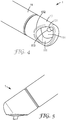
- Fig. 4 illustrates a situation in which the cap 13 and the cartridge 11 are positioned in an intermediate position between the open and the closed position.
- Fig. 4 illustrates that due to the shape of the dispensing end 111 and the shape of the cap 13 a space is formed between the cap 13 and the dispensing surface 114 in positions outside the open position. In the closed position that space is closed and preferably sealed, preferably hermetically sealed.
- the cap 13 is generally cup-shaped and has an essentially cylindrical inner shape which is sized to snugly fit onto the generally cylindrical shape of the dispensing end 111.
- the cap 13 further has a truncation which provides the cap 13 with the orifice 131.
- the truncation further preferably provides the cap 13 with a generally flat orifice region 132 which with the dispensing surface 114 forms one contiguous area in the open position (shown in Fig. 2 ) of the device 1. Accordingly the cap 13 preferably does not inhibit any removal of the dental material dispensed from the dispensing opening 113, for example by use of a spatula.
- the cap 13 In contrast in the closed position (shown in Fig. 3 ) the cap 13 entirely covers the dispensing surface 114 with the dispensing opening 113.
- the shapes of the dispensing end 111 and the cap 13 are such that in the closed position of the device 1 the inner portion of the cap 13 in combination with the dispensing surface 114 forms a hollow closed space.
- This space may be used to (for example temporarily) accommodate a portion of dental material dispensed from the dispensing opening therein until use, for example by a dentist. Accordingly the device 1 allows pre-dispensing a portion of dental material and storing the pre-dispensed portion in the space between the cap 13 and the dispensing surface 111.
- a dentist's assistant may pre-dispense a portion of the dental material and keep the pre-dispensed portion stored within the device 1.
- the portion of dental material is preferably isolated within the device 1 from the environment and thus protected against unintentional drying and/or against exposure to light.
- Latter may be particularly advantageous for use of the device 1 with light-hardenable dental materials, like light-hardenable dental composite filling materials, if the device is adapted to block light from entering into the space.
- the cap 13 and the cartridge 11 therefore may be made of a light-blocking or opaque material, for example a plastic material comprising opaque fillers, a metal (for example aluminum) coating or any other material having an appropriate light-blocking configuration.
- Fig. 5 illustrates a use of the device 1 for dispensing a portion of dental material directly on a surface, for example onto a dental pad from which the material may be picked up by a dental instrument.
- the device provides several modes of use, for example the pre-dispensing and storing of a portion of dental material, a use with a dental instrument, like a spatula, or a use for dispensing on a surface, like a dental pad. Therefore the device 1 helps facilitating the preparation of the dental material in a dental treatment and thus may help reducing efforts and costs in a dental practice.
Landscapes
- Health & Medical Sciences (AREA)
- Oral & Maxillofacial Surgery (AREA)
- Dentistry (AREA)
- Epidemiology (AREA)
- Life Sciences & Earth Sciences (AREA)
- Animal Behavior & Ethology (AREA)
- General Health & Medical Sciences (AREA)
- Public Health (AREA)
- Veterinary Medicine (AREA)
- Dental Tools And Instruments Or Auxiliary Dental Instruments (AREA)
Claims (14)
- Dispositif (1) pour distribuer un matériau dentaire, comprenant :- une cartouche (11) ayant une extrémité de distribution (111) s'étendant le long d'un axe longitudinal (A) ;∘ l'extrémité de distribution (111) ayant une ouverture de distribution (113) pour le matériau dentaire ;∘ l'extrémité de distribution (111) ayant fondamentalement une forme axialement symétrique autour de l'axe longitudinal (A), dans lequel la forme axialement symétrique a une troncature ;∘ la troncature fournissant à l'extrémité de distribution (111) une surface de distribution généralement plate (114) à travers laquelle s'étend l'ouverture de distribution (113) ;∘ la surface de distribution (114) étant orientée dans une relation non orthogonale avec l'axe longitudinal (A) ;- le dispositif comprenant en outre un capuchon (13) disposé par-dessus l'extrémité de distribution (111) ;∘ le capuchon (13) et l'extrémité de distribution (111) pouvant tourner l'un par rapport à l'autre autour de l'axe longitudinal (A) entre une position ouverte, dans laquelle un orifice (131) dans le capuchon (13) découvre la surface de distribution (114), et une position fermée, dans laquelle un espace fermé est formé entre le capuchon (13) et la surface de distribution (114).
- Dispositif selon la revendication 1, dans lequel la surface de distribution (114) est généralement plane, et dans lequel la surface de distribution (114) entoure entièrement l'ouverture de distribution (113).
- Dispositif selon la revendication 1 ou 2, dans lequel la forme axialement symétrique est généralement cylindrique, formée par une face latérale externe généralement cylindrique, une face avant libre et la surface de distribution (114), dans lequel la surface de distribution (114) forme un premier bord avec la face latérale et un deuxième bord avec la face avant.
- Dispositif selon la revendication 3, dans lequel les premier et deuxième bords forment un bord continu commun l'un avec l'autre.
- Dispositif selon la revendication 3 ou 4, dans lequel la face avant de l'extrémité de distribution (111) comprend une surface généralement sphérique et éventuellement un rayon lors de la transition entre la face avant et la face latérale.
- Dispositif selon l'une quelconque des revendications précédentes, dans lequel la surface de distribution (114) et l'axe longitudinal (A) sont inclinés l'un par rapport à l'autre selon un angle compris entre environ 30 degrés et 60 degrés.
- Dispositif selon l'une quelconque des revendications précédentes, dans lequel la cartouche (11) a une paroi de cartouche essentiellement opaque au moins pour la lumière visible à des longueurs d'onde comprises entre 380 nanomètres et 750 nanomètres.
- Dispositif selon la revendication 7, dans lequel au moins l'extrémité de distribution (111) est formée par la paroi de cartouche opaque et dans lequel en outre le capuchon (13) a une paroi de capuchon essentiellement opaque au moins pour la lumière visible.
- Dispositif selon l'une quelconque des revendications précédentes, dans lequel le capuchon (13) et la cartouche (11) sont verrouillés l'un à l'autre à l'encontre d'une séparation.
- Dispositif selon l'un quelconque revendication précédente, dans lequel la cartouche (11) forme une chambre destinée au stockage du matériau dentaire, et comprenant en outre un piston (12) pour extruder le matériau dentaire à partir de la chambre.
- Dispositif selon la revendication 10, comprenant un piston fileté (12), où le dispositif (1) est conçu de telle sorte que le matériau dentaire est extrudable par rotation du piston (12).
- Dispositif selon l'une quelconque des revendications précédentes, comprenant le matériau dentaire.
- Dispositif selon la revendication 12, dans lequel le matériau dentaire est un matériau composite dentaire comprenant une partie prédominante en poids de charges, un monomère durcissable et un photo-inducteur conçu pour amorcer le durcissement du monomère.
- Dispositif selon la revendication 13, dans lequel le capuchon comprend un indicateur qui indique une couleur de dent associée à la couleur du matériau composite dentaire.
Priority Applications (1)
| Application Number | Priority Date | Filing Date | Title |
|---|---|---|---|
| EP14750109.2A EP3027140B1 (fr) | 2013-07-31 | 2014-07-24 | Dispositif pour distribution de matériau dentaire |
Applications Claiming Priority (3)
| Application Number | Priority Date | Filing Date | Title |
|---|---|---|---|
| EP13178652.7A EP2832311A1 (fr) | 2013-07-31 | 2013-07-31 | Dispositif pour distribution de matériau dentaire |
| EP14750109.2A EP3027140B1 (fr) | 2013-07-31 | 2014-07-24 | Dispositif pour distribution de matériau dentaire |
| PCT/US2014/048011 WO2015017245A1 (fr) | 2013-07-31 | 2014-07-24 | Dispositif de distribution d'un matériau dentaire |
Publications (2)
| Publication Number | Publication Date |
|---|---|
| EP3027140A1 EP3027140A1 (fr) | 2016-06-08 |
| EP3027140B1 true EP3027140B1 (fr) | 2018-02-21 |
Family
ID=48877143
Family Applications (2)
| Application Number | Title | Priority Date | Filing Date |
|---|---|---|---|
| EP13178652.7A Ceased EP2832311A1 (fr) | 2013-07-31 | 2013-07-31 | Dispositif pour distribution de matériau dentaire |
| EP14750109.2A Not-in-force EP3027140B1 (fr) | 2013-07-31 | 2014-07-24 | Dispositif pour distribution de matériau dentaire |
Family Applications Before (1)
| Application Number | Title | Priority Date | Filing Date |
|---|---|---|---|
| EP13178652.7A Ceased EP2832311A1 (fr) | 2013-07-31 | 2013-07-31 | Dispositif pour distribution de matériau dentaire |
Country Status (3)
| Country | Link |
|---|---|
| US (1) | US9737378B2 (fr) |
| EP (2) | EP2832311A1 (fr) |
| WO (1) | WO2015017245A1 (fr) |
Families Citing this family (4)
| Publication number | Priority date | Publication date | Assignee | Title |
|---|---|---|---|---|
| US20170071699A1 (en) * | 2014-03-04 | 2017-03-16 | Tokuyama Dental Corporation | Plastic Container for Containing Dental Adhesive Composition |
| DE102016120683A1 (de) * | 2016-10-28 | 2018-05-03 | Carl Zeiss Microscopy Gmbh | Lichtblattmikroskop |
| JP1667317S (fr) * | 2020-01-31 | 2020-08-31 | ||
| JP1667316S (fr) * | 2020-01-31 | 2020-08-31 |
Family Cites Families (16)
| Publication number | Priority date | Publication date | Assignee | Title |
|---|---|---|---|---|
| US419236A (en) | 1890-01-14 | Flour-bolt | ||
| US3339810A (en) * | 1966-01-26 | 1967-09-05 | Block Charles | Dispensing apparatus |
| US4391590A (en) * | 1981-04-09 | 1983-07-05 | Dentsply Research & Development Corp. | Cartridge for viscous material |
| US4569662A (en) * | 1981-10-26 | 1986-02-11 | Dragan William B | Bulk cartridge for packaging and dispensing a dental material |
| DE19651139C2 (de) * | 1996-12-10 | 1999-04-15 | Heraeus Kulzer Gmbh | Kartusche zur Aufnahme von pastösem Material |
| USD419236S (en) | 1998-10-02 | 2000-01-18 | 3M Innovative Properties Company | Syringe-type applicator |
| US6524103B1 (en) * | 1999-09-23 | 2003-02-25 | Ivoclar Ag | Cartridge and dental applicator |
| DE10040732C2 (de) | 2000-08-17 | 2002-11-07 | 3M Espe Ag | Geschlitzter Kolben |
| WO2002076323A1 (fr) * | 2001-03-26 | 2002-10-03 | Schütz-Dental GmbH | Dispositif d'application d'une pate d'obturation dentaire |
| US7198619B2 (en) * | 2002-03-26 | 2007-04-03 | Ultradent Products, Inc. | Valve syringe |
| EP1543795A1 (fr) * | 2003-12-17 | 2005-06-22 | DENTSPLY DETREY GmbH | Embout distributeur à usage unique pour une cartouche ditributeur de substance dentale à usages multiples et système d'application d' une substance dentale avec un tel embout |
| US7261559B2 (en) | 2005-04-01 | 2007-08-28 | Ultradent Products, Inc. | Syringe delivery system for dispensing a dental composite or other highly viscous material |
| DE202006009628U1 (de) * | 2006-06-20 | 2007-10-31 | Ernst Mühlbauer Gmbh & Co. Kg | Spritze zum Ausbringen viskoser Flüssigkeiten oder pastenförmiger Pasten |
| JP5833568B2 (ja) * | 2009-12-29 | 2015-12-16 | スリーエム イノベイティブ プロパティズ カンパニー | 仮着用セメントのための歯科用自動混合方法、用具、及び組成物 |
| US20120064481A1 (en) * | 2010-09-13 | 2012-03-15 | Wade Cannon | Composite delivery system |
| WO2013016642A2 (fr) * | 2011-07-28 | 2013-01-31 | 3M Innovative Properties Company | Dispositif de distribution d'une substance dentaire et procédé de distribution |
-
2013
- 2013-07-31 EP EP13178652.7A patent/EP2832311A1/fr not_active Ceased
-
2014
- 2014-07-24 US US14/904,839 patent/US9737378B2/en active Active
- 2014-07-24 EP EP14750109.2A patent/EP3027140B1/fr not_active Not-in-force
- 2014-07-24 WO PCT/US2014/048011 patent/WO2015017245A1/fr not_active Ceased
Also Published As
| Publication number | Publication date |
|---|---|
| EP3027140A1 (fr) | 2016-06-08 |
| EP2832311A1 (fr) | 2015-02-04 |
| US20160166356A1 (en) | 2016-06-16 |
| WO2015017245A1 (fr) | 2015-02-05 |
| US9737378B2 (en) | 2017-08-22 |
Similar Documents
| Publication | Publication Date | Title |
|---|---|---|
| EP2991577B1 (fr) | Stylo applicateur pour matériau dentaire | |
| EP2736447B1 (fr) | Dispositif de distribution d'une substance dentaire et procédé de distribution | |
| EP3027140B1 (fr) | Dispositif pour distribution de matériau dentaire | |
| US5692642A (en) | Fluid dispenser adapter and method of use | |
| EP3325052B1 (fr) | Dispositif un ensemble piston, procédé d'assemblage de ce dispositif et procédé de fabrication de l'ensemble piston | |
| CA2624536C (fr) | Seringue d'injection ayant de multiples barillets permettant d'administrer une composition dentaire | |
| JP4958892B2 (ja) | 歯科材料または高粘性材料を分配する注射器送出システム | |
| JP3209773B2 (ja) | 歯科用計量カートリッジ | |
| US4863072A (en) | Single hand operable dental composite package | |
| US7494339B2 (en) | Compositions for use as dental crowns and methods for preparing dental crowns | |
| US9668826B2 (en) | Handheld viscous dental paste dispenser | |
| US20120064481A1 (en) | Composite delivery system | |
| JPS60194962A (ja) | 歯科用注射器 | |
| US6569122B2 (en) | Syringe apparatus for delivering light activated materials | |
| US20070077538A1 (en) | Epoxy based oil free root canal sealer | |
| EP3479793B1 (fr) | Emballage pour matériaux dentaire visqueux | |
| US20250169921A1 (en) | Dispenser assembly with syringe and capsule | |
| EP4731123A1 (fr) | Article dentaire avec dispositif d'application, composition lubrifiante et matériau dentaire | |
| WO2026027967A1 (fr) | Procédé de chauffage d'un matériau composite dentaire et kit de pièces |
Legal Events
| Date | Code | Title | Description |
|---|---|---|---|
| PUAI | Public reference made under article 153(3) epc to a published international application that has entered the european phase |
Free format text: ORIGINAL CODE: 0009012 |
|
| 17P | Request for examination filed |
Effective date: 20160115 |
|
| AK | Designated contracting states |
Kind code of ref document: A1 Designated state(s): AL AT BE BG CH CY CZ DE DK EE ES FI FR GB GR HR HU IE IS IT LI LT LU LV MC MK MT NL NO PL PT RO RS SE SI SK SM TR |
|
| AX | Request for extension of the european patent |
Extension state: BA ME |
|
| DAX | Request for extension of the european patent (deleted) | ||
| STAA | Information on the status of an ep patent application or granted ep patent |
Free format text: STATUS: EXAMINATION IS IN PROGRESS |
|
| 17Q | First examination report despatched |
Effective date: 20161221 |
|
| REG | Reference to a national code |
Ref country code: DE Ref legal event code: R079 Ref document number: 602014021249 Country of ref document: DE Free format text: PREVIOUS MAIN CLASS: A61C0005060000 Ipc: A61C0001160000 |
|
| GRAP | Despatch of communication of intention to grant a patent |
Free format text: ORIGINAL CODE: EPIDOSNIGR1 |
|
| STAA | Information on the status of an ep patent application or granted ep patent |
Free format text: STATUS: GRANT OF PATENT IS INTENDED |
|
| RIC1 | Information provided on ipc code assigned before grant |
Ipc: A61C 1/16 20060101AFI20170904BHEP Ipc: A61C 5/62 20170101ALI20170904BHEP |
|
| INTG | Intention to grant announced |
Effective date: 20171011 |
|
| GRAS | Grant fee paid |
Free format text: ORIGINAL CODE: EPIDOSNIGR3 |
|
| GRAA | (expected) grant |
Free format text: ORIGINAL CODE: 0009210 |
|
| STAA | Information on the status of an ep patent application or granted ep patent |
Free format text: STATUS: THE PATENT HAS BEEN GRANTED |
|
| AK | Designated contracting states |
Kind code of ref document: B1 Designated state(s): AL AT BE BG CH CY CZ DE DK EE ES FI FR GB GR HR HU IE IS IT LI LT LU LV MC MK MT NL NO PL PT RO RS SE SI SK SM TR |
|
| REG | Reference to a national code |
Ref country code: GB Ref legal event code: FG4D |
|
| REG | Reference to a national code |
Ref country code: CH Ref legal event code: EP |
|
| REG | Reference to a national code |
Ref country code: AT Ref legal event code: REF Ref document number: 970858 Country of ref document: AT Kind code of ref document: T Effective date: 20180315 |
|
| REG | Reference to a national code |
Ref country code: IE Ref legal event code: FG4D |
|
| REG | Reference to a national code |
Ref country code: DE Ref legal event code: R096 Ref document number: 602014021249 Country of ref document: DE |
|
| REG | Reference to a national code |
Ref country code: NL Ref legal event code: MP Effective date: 20180221 |
|
| REG | Reference to a national code |
Ref country code: LT Ref legal event code: MG4D |
|
| REG | Reference to a national code |
Ref country code: AT Ref legal event code: MK05 Ref document number: 970858 Country of ref document: AT Kind code of ref document: T Effective date: 20180221 |
|
| PG25 | Lapsed in a contracting state [announced via postgrant information from national office to epo] |
Ref country code: ES Free format text: LAPSE BECAUSE OF FAILURE TO SUBMIT A TRANSLATION OF THE DESCRIPTION OR TO PAY THE FEE WITHIN THE PRESCRIBED TIME-LIMIT Effective date: 20180221 Ref country code: NL Free format text: LAPSE BECAUSE OF FAILURE TO SUBMIT A TRANSLATION OF THE DESCRIPTION OR TO PAY THE FEE WITHIN THE PRESCRIBED TIME-LIMIT Effective date: 20180221 Ref country code: LT Free format text: LAPSE BECAUSE OF FAILURE TO SUBMIT A TRANSLATION OF THE DESCRIPTION OR TO PAY THE FEE WITHIN THE PRESCRIBED TIME-LIMIT Effective date: 20180221 Ref country code: HR Free format text: LAPSE BECAUSE OF FAILURE TO SUBMIT A TRANSLATION OF THE DESCRIPTION OR TO PAY THE FEE WITHIN THE PRESCRIBED TIME-LIMIT Effective date: 20180221 Ref country code: FI Free format text: LAPSE BECAUSE OF FAILURE TO SUBMIT A TRANSLATION OF THE DESCRIPTION OR TO PAY THE FEE WITHIN THE PRESCRIBED TIME-LIMIT Effective date: 20180221 Ref country code: NO Free format text: LAPSE BECAUSE OF FAILURE TO SUBMIT A TRANSLATION OF THE DESCRIPTION OR TO PAY THE FEE WITHIN THE PRESCRIBED TIME-LIMIT Effective date: 20180521 Ref country code: CY Free format text: LAPSE BECAUSE OF FAILURE TO SUBMIT A TRANSLATION OF THE DESCRIPTION OR TO PAY THE FEE WITHIN THE PRESCRIBED TIME-LIMIT Effective date: 20180221 |
|
| PG25 | Lapsed in a contracting state [announced via postgrant information from national office to epo] |
Ref country code: SE Free format text: LAPSE BECAUSE OF FAILURE TO SUBMIT A TRANSLATION OF THE DESCRIPTION OR TO PAY THE FEE WITHIN THE PRESCRIBED TIME-LIMIT Effective date: 20180221 Ref country code: LV Free format text: LAPSE BECAUSE OF FAILURE TO SUBMIT A TRANSLATION OF THE DESCRIPTION OR TO PAY THE FEE WITHIN THE PRESCRIBED TIME-LIMIT Effective date: 20180221 Ref country code: GR Free format text: LAPSE BECAUSE OF FAILURE TO SUBMIT A TRANSLATION OF THE DESCRIPTION OR TO PAY THE FEE WITHIN THE PRESCRIBED TIME-LIMIT Effective date: 20180522 Ref country code: AT Free format text: LAPSE BECAUSE OF FAILURE TO SUBMIT A TRANSLATION OF THE DESCRIPTION OR TO PAY THE FEE WITHIN THE PRESCRIBED TIME-LIMIT Effective date: 20180221 Ref country code: RS Free format text: LAPSE BECAUSE OF FAILURE TO SUBMIT A TRANSLATION OF THE DESCRIPTION OR TO PAY THE FEE WITHIN THE PRESCRIBED TIME-LIMIT Effective date: 20180221 Ref country code: BG Free format text: LAPSE BECAUSE OF FAILURE TO SUBMIT A TRANSLATION OF THE DESCRIPTION OR TO PAY THE FEE WITHIN THE PRESCRIBED TIME-LIMIT Effective date: 20180521 |
|
| PG25 | Lapsed in a contracting state [announced via postgrant information from national office to epo] |
Ref country code: IT Free format text: LAPSE BECAUSE OF FAILURE TO SUBMIT A TRANSLATION OF THE DESCRIPTION OR TO PAY THE FEE WITHIN THE PRESCRIBED TIME-LIMIT Effective date: 20180221 Ref country code: AL Free format text: LAPSE BECAUSE OF FAILURE TO SUBMIT A TRANSLATION OF THE DESCRIPTION OR TO PAY THE FEE WITHIN THE PRESCRIBED TIME-LIMIT Effective date: 20180221 Ref country code: EE Free format text: LAPSE BECAUSE OF FAILURE TO SUBMIT A TRANSLATION OF THE DESCRIPTION OR TO PAY THE FEE WITHIN THE PRESCRIBED TIME-LIMIT Effective date: 20180221 Ref country code: PL Free format text: LAPSE BECAUSE OF FAILURE TO SUBMIT A TRANSLATION OF THE DESCRIPTION OR TO PAY THE FEE WITHIN THE PRESCRIBED TIME-LIMIT Effective date: 20180221 Ref country code: RO Free format text: LAPSE BECAUSE OF FAILURE TO SUBMIT A TRANSLATION OF THE DESCRIPTION OR TO PAY THE FEE WITHIN THE PRESCRIBED TIME-LIMIT Effective date: 20180221 |
|
| REG | Reference to a national code |
Ref country code: DE Ref legal event code: R097 Ref document number: 602014021249 Country of ref document: DE |
|
| PG25 | Lapsed in a contracting state [announced via postgrant information from national office to epo] |
Ref country code: DK Free format text: LAPSE BECAUSE OF FAILURE TO SUBMIT A TRANSLATION OF THE DESCRIPTION OR TO PAY THE FEE WITHIN THE PRESCRIBED TIME-LIMIT Effective date: 20180221 Ref country code: SM Free format text: LAPSE BECAUSE OF FAILURE TO SUBMIT A TRANSLATION OF THE DESCRIPTION OR TO PAY THE FEE WITHIN THE PRESCRIBED TIME-LIMIT Effective date: 20180221 Ref country code: CZ Free format text: LAPSE BECAUSE OF FAILURE TO SUBMIT A TRANSLATION OF THE DESCRIPTION OR TO PAY THE FEE WITHIN THE PRESCRIBED TIME-LIMIT Effective date: 20180221 Ref country code: SK Free format text: LAPSE BECAUSE OF FAILURE TO SUBMIT A TRANSLATION OF THE DESCRIPTION OR TO PAY THE FEE WITHIN THE PRESCRIBED TIME-LIMIT Effective date: 20180221 |
|
| PLBE | No opposition filed within time limit |
Free format text: ORIGINAL CODE: 0009261 |
|
| STAA | Information on the status of an ep patent application or granted ep patent |
Free format text: STATUS: NO OPPOSITION FILED WITHIN TIME LIMIT |
|
| 26N | No opposition filed |
Effective date: 20181122 |
|
| PG25 | Lapsed in a contracting state [announced via postgrant information from national office to epo] |
Ref country code: SI Free format text: LAPSE BECAUSE OF FAILURE TO SUBMIT A TRANSLATION OF THE DESCRIPTION OR TO PAY THE FEE WITHIN THE PRESCRIBED TIME-LIMIT Effective date: 20180221 |
|
| GBPC | Gb: european patent ceased through non-payment of renewal fee |
Effective date: 20180724 |
|
| PG25 | Lapsed in a contracting state [announced via postgrant information from national office to epo] |
Ref country code: LU Free format text: LAPSE BECAUSE OF NON-PAYMENT OF DUE FEES Effective date: 20180724 Ref country code: MC Free format text: LAPSE BECAUSE OF FAILURE TO SUBMIT A TRANSLATION OF THE DESCRIPTION OR TO PAY THE FEE WITHIN THE PRESCRIBED TIME-LIMIT Effective date: 20180221 |
|
| REG | Reference to a national code |
Ref country code: BE Ref legal event code: MM Effective date: 20180731 |
|
| REG | Reference to a national code |
Ref country code: IE Ref legal event code: MM4A |
|
| PG25 | Lapsed in a contracting state [announced via postgrant information from national office to epo] |
Ref country code: IE Free format text: LAPSE BECAUSE OF NON-PAYMENT OF DUE FEES Effective date: 20180724 Ref country code: GB Free format text: LAPSE BECAUSE OF NON-PAYMENT OF DUE FEES Effective date: 20180724 Ref country code: FR Free format text: LAPSE BECAUSE OF NON-PAYMENT OF DUE FEES Effective date: 20180731 |
|
| PG25 | Lapsed in a contracting state [announced via postgrant information from national office to epo] |
Ref country code: BE Free format text: LAPSE BECAUSE OF NON-PAYMENT OF DUE FEES Effective date: 20180731 |
|
| PG25 | Lapsed in a contracting state [announced via postgrant information from national office to epo] |
Ref country code: MT Free format text: LAPSE BECAUSE OF NON-PAYMENT OF DUE FEES Effective date: 20180724 |
|
| PG25 | Lapsed in a contracting state [announced via postgrant information from national office to epo] |
Ref country code: TR Free format text: LAPSE BECAUSE OF FAILURE TO SUBMIT A TRANSLATION OF THE DESCRIPTION OR TO PAY THE FEE WITHIN THE PRESCRIBED TIME-LIMIT Effective date: 20180221 |
|
| PG25 | Lapsed in a contracting state [announced via postgrant information from national office to epo] |
Ref country code: PT Free format text: LAPSE BECAUSE OF FAILURE TO SUBMIT A TRANSLATION OF THE DESCRIPTION OR TO PAY THE FEE WITHIN THE PRESCRIBED TIME-LIMIT Effective date: 20180221 |
|
| PG25 | Lapsed in a contracting state [announced via postgrant information from national office to epo] |
Ref country code: MK Free format text: LAPSE BECAUSE OF NON-PAYMENT OF DUE FEES Effective date: 20180221 Ref country code: HU Free format text: LAPSE BECAUSE OF FAILURE TO SUBMIT A TRANSLATION OF THE DESCRIPTION OR TO PAY THE FEE WITHIN THE PRESCRIBED TIME-LIMIT; INVALID AB INITIO Effective date: 20140724 |
|
| PG25 | Lapsed in a contracting state [announced via postgrant information from national office to epo] |
Ref country code: IS Free format text: LAPSE BECAUSE OF FAILURE TO SUBMIT A TRANSLATION OF THE DESCRIPTION OR TO PAY THE FEE WITHIN THE PRESCRIBED TIME-LIMIT Effective date: 20180621 |
|
| PGFP | Annual fee paid to national office [announced via postgrant information from national office to epo] |
Ref country code: DE Payment date: 20200714 Year of fee payment: 7 |
|
| PGFP | Annual fee paid to national office [announced via postgrant information from national office to epo] |
Ref country code: CH Payment date: 20200716 Year of fee payment: 7 |
|
| REG | Reference to a national code |
Ref country code: DE Ref legal event code: R119 Ref document number: 602014021249 Country of ref document: DE |
|
| REG | Reference to a national code |
Ref country code: CH Ref legal event code: PL |
|
| PG25 | Lapsed in a contracting state [announced via postgrant information from national office to epo] |
Ref country code: LI Free format text: LAPSE BECAUSE OF NON-PAYMENT OF DUE FEES Effective date: 20210731 Ref country code: DE Free format text: LAPSE BECAUSE OF NON-PAYMENT OF DUE FEES Effective date: 20220201 Ref country code: CH Free format text: LAPSE BECAUSE OF NON-PAYMENT OF DUE FEES Effective date: 20210731 |