EP3027402B1 - Reifenaufbautrommel mit einschiebbaren sektoren - Google Patents
Reifenaufbautrommel mit einschiebbaren sektoren Download PDFInfo
- Publication number
- EP3027402B1 EP3027402B1 EP14759015.2A EP14759015A EP3027402B1 EP 3027402 B1 EP3027402 B1 EP 3027402B1 EP 14759015 A EP14759015 A EP 14759015A EP 3027402 B1 EP3027402 B1 EP 3027402B1
- Authority
- EP
- European Patent Office
- Prior art keywords
- sectors
- drum
- face
- cam
- axis
- Prior art date
- Legal status (The legal status is an assumption and is not a legal conclusion. Google has not performed a legal analysis and makes no representation as to the accuracy of the status listed.)
- Active
Links
Images







Classifications
-
- B—PERFORMING OPERATIONS; TRANSPORTING
- B29—WORKING OF PLASTICS; WORKING OF SUBSTANCES IN A PLASTIC STATE IN GENERAL
- B29D—PRODUCING PARTICULAR ARTICLES FROM PLASTICS OR FROM SUBSTANCES IN A PLASTIC STATE
- B29D30/00—Producing pneumatic or solid tyres or parts thereof
- B29D30/06—Pneumatic tyres or parts thereof (e.g. produced by casting, moulding, compression moulding, injection moulding, centrifugal casting)
- B29D30/08—Building tyres
- B29D30/20—Building tyres by the flat-tyre method, i.e. building on cylindrical drums
- B29D30/24—Drums
- B29D30/242—Drums for manufacturing substantially cylindrical tyre components without cores or beads, e.g. treads or belts
-
- B—PERFORMING OPERATIONS; TRANSPORTING
- B29—WORKING OF PLASTICS; WORKING OF SUBSTANCES IN A PLASTIC STATE IN GENERAL
- B29D—PRODUCING PARTICULAR ARTICLES FROM PLASTICS OR FROM SUBSTANCES IN A PLASTIC STATE
- B29D30/00—Producing pneumatic or solid tyres or parts thereof
- B29D30/06—Pneumatic tyres or parts thereof (e.g. produced by casting, moulding, compression moulding, injection moulding, centrifugal casting)
- B29D30/08—Building tyres
- B29D30/10—Building tyres on round cores, i.e. the shape of the core is approximately identical with the shape of the completed tyre
- B29D30/12—Cores
-
- B—PERFORMING OPERATIONS; TRANSPORTING
- B29—WORKING OF PLASTICS; WORKING OF SUBSTANCES IN A PLASTIC STATE IN GENERAL
- B29D—PRODUCING PARTICULAR ARTICLES FROM PLASTICS OR FROM SUBSTANCES IN A PLASTIC STATE
- B29D30/00—Producing pneumatic or solid tyres or parts thereof
- B29D30/06—Pneumatic tyres or parts thereof (e.g. produced by casting, moulding, compression moulding, injection moulding, centrifugal casting)
- B29D30/08—Building tyres
- B29D30/20—Building tyres by the flat-tyre method, i.e. building on cylindrical drums
- B29D30/24—Drums
-
- B—PERFORMING OPERATIONS; TRANSPORTING
- B29—WORKING OF PLASTICS; WORKING OF SUBSTANCES IN A PLASTIC STATE IN GENERAL
- B29D—PRODUCING PARTICULAR ARTICLES FROM PLASTICS OR FROM SUBSTANCES IN A PLASTIC STATE
- B29D30/00—Producing pneumatic or solid tyres or parts thereof
- B29D30/06—Pneumatic tyres or parts thereof (e.g. produced by casting, moulding, compression moulding, injection moulding, centrifugal casting)
- B29D30/08—Building tyres
- B29D30/20—Building tyres by the flat-tyre method, i.e. building on cylindrical drums
- B29D30/24—Drums
- B29D30/26—Accessories or details, e.g. membranes, transfer rings
-
- B—PERFORMING OPERATIONS; TRANSPORTING
- B29—WORKING OF PLASTICS; WORKING OF SUBSTANCES IN A PLASTIC STATE IN GENERAL
- B29D—PRODUCING PARTICULAR ARTICLES FROM PLASTICS OR FROM SUBSTANCES IN A PLASTIC STATE
- B29D30/00—Producing pneumatic or solid tyres or parts thereof
- B29D30/06—Pneumatic tyres or parts thereof (e.g. produced by casting, moulding, compression moulding, injection moulding, centrifugal casting)
- B29D30/08—Building tyres
- B29D30/20—Building tyres by the flat-tyre method, i.e. building on cylindrical drums
- B29D30/24—Drums
- B29D30/26—Accessories or details, e.g. membranes, transfer rings
- B29D2030/2642—Adjusting the diameter of the drum, to match its circumference with the length of ply
-
- B—PERFORMING OPERATIONS; TRANSPORTING
- B29—WORKING OF PLASTICS; WORKING OF SUBSTANCES IN A PLASTIC STATE IN GENERAL
- B29D—PRODUCING PARTICULAR ARTICLES FROM PLASTICS OR FROM SUBSTANCES IN A PLASTIC STATE
- B29D30/00—Producing pneumatic or solid tyres or parts thereof
- B29D30/06—Pneumatic tyres or parts thereof (e.g. produced by casting, moulding, compression moulding, injection moulding, centrifugal casting)
- B29D30/08—Building tyres
- B29D30/20—Building tyres by the flat-tyre method, i.e. building on cylindrical drums
- B29D30/24—Drums
- B29D30/26—Accessories or details, e.g. membranes, transfer rings
- B29D2030/265—Radially expandable and contractable drum comprising a set of circumferentially arranged elastic, flexible elements, e.g. blades or laminas, with or without expandable annular sleeve or bladder
-
- B—PERFORMING OPERATIONS; TRANSPORTING
- B29—WORKING OF PLASTICS; WORKING OF SUBSTANCES IN A PLASTIC STATE IN GENERAL
- B29D—PRODUCING PARTICULAR ARTICLES FROM PLASTICS OR FROM SUBSTANCES IN A PLASTIC STATE
- B29D30/00—Producing pneumatic or solid tyres or parts thereof
- B29D30/06—Pneumatic tyres or parts thereof (e.g. produced by casting, moulding, compression moulding, injection moulding, centrifugal casting)
- B29D30/08—Building tyres
- B29D30/20—Building tyres by the flat-tyre method, i.e. building on cylindrical drums
- B29D30/24—Drums
- B29D30/26—Accessories or details, e.g. membranes, transfer rings
- B29D2030/2657—Radially expandable and contractable drum comprising a set of circumferentially arranged rigid elements, e.g. fingers or arms
Definitions
- the assembly of the tread forming elements of a wheel tire casing blank takes place on a forming drum, also called crown form.
- These elements mainly include raw gum. Once assembled, the tread is removed from the drum and deposited on a carcass made separately. The combination of the two forms a bandage. After forming the latter, we obtain the raw blank which is then baked for vulcanization of the gum.
- WO 2013/054051 on behalf of the plaintiffs discloses a drum which includes primary and secondary sectors forming its circumferential face. These sectors are movable radially to the axis of rotation of the drum to allow the tread to be extracted once it is made and also to adapt the diameter of the drum according to that of the tread to be made.
- the primary sectors are also mobile in the axial direction relative to the secondary sectors. Thus, when it is desired to increase the diameter of the drum, the sectors are removed from the axis and the secondary sectors of the primary sectors are brought closer in the axial direction in order to fill the spaces appeared between the primary sectors and to restore the continuity of the face. circumferential so that it serves as support for the elements of the tread.
- the axis of certain sectors is brought closer so as to leave gaps between the other sectors which have remained immobile. It is then possible to grasp the band by introducing gripping means in the spaces thus appeared. Then, all the sectors are moved radially so as to completely release the strip with respect to the drum. This is the collapsing operation.
- the sector control mechanism comprises for this purpose a first cam adapted to move certain sectors and a second cam adapted to move the others.
- An actuator makes it possible to rotate one of the cams relative to the other and thus, at the beginning of the process, to bring the first sectors of the axis closer together without moving the others.
- This drum is however likely to be improved. Indeed, the control of the sectors during the process above requires first to control the actuator to rotate a cam relative to the other then to control another actuator ensuring the simultaneous movement of the two cams. The control of the drum for the release of the tape is therefore relatively complicated. And the mechanism is also complex.
- This drum has twelve sectors, which may seem to be an insufficient number of elements to ensure the continuity of the surface.
- the differences in the geometry of the circumferential surface over the diameter adjustment range of the drum can be significant and cause defects concerning the uniformity of the manufactured tire casing.
- the difficulty is to be able to control all sectors, the cams having a limited space to accommodate ramps, each ramp being connected to a given sector.
- An object of the invention is to simplify the process and mechanism for strip release.
- Another object of the invention is to provide a mechanism for controlling a relatively large number of sectors.
- a monotonic function is a function whose direction of variation does not change. On a given interval, it is therefore a growing function or a decreasing function but not both.
- monotonic movement we mean that the movement of the cam does not change direction.
- the sectors comprise sectors of a first type and sectors of a second type able to bear in the radial direction against the sectors of the first type, the cam being arranged so that the sectors of the first type are displaced. thanks to the ramps on the first face of the cam, the sectors of the second type being moved through the ramps on the second face of the cam.
- the drum is arranged so that the sectors of the first type, after the beginning of their displacement by the cam, are received in clearances in the sectors of the second type.
- some of the ramps capable of controlling the displacement of certain sectors have an arcuate section coaxial with an axis of rotation of the cam.
- This coaxial section does not cause radial movement of the corresponding sectors when it is traversed by a follower member connected to the sectors.
- cams are at least two in number.
- At least some of the sectors, and preferably all, are mounted movable relative to the support in a predetermined direction non-radial to the axis of rotation and intercepting the latter.
- This mode of displacement of the sectors makes it possible to simplify their geometrical definition and to reduce the energy to be supplied for their relative displacements, while obtaining a quasi continuous working surface.
- the drum comprises at least one member slidably mounted relative to the support in the direction of the axis of rotation and connected to several of the sectors.
- the drum is arranged so that the sectors are contiguous in the circumferential direction.
- each sector has two planar main lateral faces arranged to come opposite the homologous faces of the adjacent sectors.
- the eraser placed on the surface of the drum being hot the treatment of this surface facilitates its extraction thereafter.
- Also provided according to the invention is a method of manufacturing a tire casing, as defined in claim 11, wherein at least a portion of a tread of a green blank of the casing is assembled on a casing. drum according to the invention.
- a drum 2 according to one embodiment of the invention.
- This drum is used for assembling the elements forming a tread for a rough tire blank.
- the tire is intended for a vehicle wheel which may be a commercial vehicle, a light-type vehicle, a passenger vehicle, a heavy-duty vehicle or a civil engineering machine.
- the drum comprises a support 14 illustrated in particular at figure 19 and having a generally symmetrical shape of axis revolution 12 which forms the axis of rotation of the drum.
- the axial direction designates a direction parallel to the axis 12 and the radial direction any direction radial to the latter, that is to say which is perpendicular thereto and which therefore intercepts axis.
- the surface of this tooling Being an assembly tool from a top to a rough, the surface of this tooling is almost continuous, variable diameter and allows in particular the construction of a tread by successive stacking strips of hot gum laid hot. For this purpose, it has an anti-stick surface treatment to allow the installation of the hot gum and facilitate its extraction thereafter.
- the circumferential face of the drum is particularly free of relief or step-like recess often encountered in drums of the state of the art. This avoids the deformation of rubber strips and manufacturing defects such as blisters appearing during cooking.
- the drum 2 has sectors 6c, 6v, which extend peripherally of the support 14 to form the circumferential face 10 of the drum which constitutes the working face on which the elements of the tread are arranged.
- This face 10 has, in this case, a generally circular cylindrical shape in a plane perpendicular to the axis 12.
- the drum thus forms here what the skilled person often refers to a "flat shape”.
- each sector is mounted to move in a linear direction inclined relative to the axis 12 and intercepting this axis without being perpendicular thereto.
- each sector follows a rectilinear trajectory with respect to the axis, which makes it possible to simplify the definition and the machining of the faces of each sector, in particular their lateral faces in contact with each other, as well as the guiding mechanism of these sectors.
- the side faces are flat, which makes them easily machinable.
- Each sector has a plane of symmetry in which is inscribed the axis 12. It has a cylindrical outer face 10 having contours of generally trapezoidal shape. These contours are delimited by four flat faces, namely two end faces 7 and 8, the face 7 being shorter than the face 8 in the circumferential direction, and two lateral faces 9. The faces 7 and 8 are perpendicular to the axis 12.
- Sectors 6c of the first type are called “key sectors” and sectors 6v of the second type "vault sectors”. These two types of sectors thus form two respective subsets. All sectors of the first type are identical to each other. It is the same for sectors of the second type. Following the circumferential direction to the axis 12, the sectors of the first type are arranged alternately with those of the second type but are arranged head to tail with respect thereto.
- the drum is arranged so that the sectors can come into mutual contact in the circumferential direction by their side faces 9. Each sector thus comes into contact with the two adjacent sectors in the succession.
- the key sectors and the vaulted sectors being regularly alternated, each key sector is contiguous with two sectors vaults and vice versa.
- each key sector is supported in the direction of the axis on the two adjacent vault areas.
- a radial bias exerted on this sector is reported on the two adjacent vault areas.
- the sectors can be moved relative to each other to change the diameter of the face 10.
- the configurations of smaller and larger diameters of the drum have been illustrated respectively to Figures 2 and 3 , the figure 1 showing its average diameter configuration.
- the distance between the small end faces 7 of the subsets is shorter than the distance between their large end faces 8. This is how the sectors of each subset exceed those of the other under - Together in the axial direction by their large ends 8.
- the continuous circumferential surface offered for the realization of the tread is delimited by the small faces 7.
- the small ends 7 of the sectors of any one of the subsets extend in the same plane as the large end faces 8 of the sectors of the other subset. This is the entire external face of the sectors that forms the working drum.
- the drum is set to its average diameter, and the outer face 10 is perfectly cylindrical.
- the first mechanism allows the adjustment of the diameter of the tooling ensuring the dimensional coverage required.
- this diameter can be varied over a range of 100 mm.
- each sector 6c, 6v slides relative to the support in a predetermined direction 13 non-radial to the axis 12 and intercepting this axis .
- the sector remains parallel to the axis 12.
- the angle formed by this direction and the axis is here the same for all sectors.
- this mechanism is arranged so that any of the sectors can not be moved in this way relative to the support without the other sectors also move relative to the support in the predetermined directions that are specific to them. More specifically, when the sectors of any one of the subsets move in the direction 13 relative to the support, this displacement has a component along the axis oriented in one direction and the sectors of the other under -together move with a component along the axis oriented in a second direction opposite to the first direction. The key sectors therefore move in a first direction along the axis and the sectors vault in the opposite direction, their absolute speed being the same. At any moment of the movement, the sectors therefore remain all at the same distance from the axis 12.
- the two subsets are the image of each other by axial symmetry.
- the axis of symmetry is perpendicular to the axis of rotation 12.
- figure 1 the median transverse plane 16 of the drum, perpendicular to the axis 12.
- the small end faces 7 of all sectors extend at the same distance from this plane. It is the same with their large end faces 8.
- the diameter range to be covered and the width of the useful area on the tooling can be modified by adjusting the geometry of the lateral faces 9 combined with the value of the angle of the direction 13, and over the length of the sectors combined with their course relative to the median plane.
- each sector is mounted movably relative to the support in a direction radial to the axis 12.
- the sectors are movable between two positions.
- the first is a working position allowing the construction of the tread, the tooling having the diameter chosen for this work, as illustrated in FIG. figure 5 .
- the second is a collapsed position of the tooling obtained at the end of the radial movement of the sectors in the direction of the axis. This position allows the separation of the sectors with respect to the tread made and removal of the tool from the inside thereof.
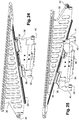
- this mechanism is arranged so that it first causes the displacement of the vault sectors 6v in the direction of the axis without modifying the radial position of the key sectors 6c as illustrated in FIG.
- figure 6 then causes the radial displacement of all the sectors simultaneously, as illustrated by figure 7 .
- the key sectors have lateral clearances under their lateral faces 9 enabling them to receive part of the adjacent vaulted sectors at the end of the first phase of the movement. So we see that it is advantageous to provide an even number of sectors.
- the vault areas descend first and alternate with the key sectors, they form support zones for the band that are regularly distributed and maintain dimensional uniformity pending its transfer to another position and during this transfer.
- the diameter of the cylinder is chosen to correspond to the average diameter of the diameter variation range to be covered with the tool, in order to limit the geometric differences between this mean diameter and the diameters minimum and maximum drum setting.
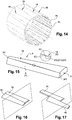
- Each side face 9 is inscribed in a plane inclined relative to the axis 12, the two faces 9 of the same sector forming a corner.
- Each edge 18 forming the intersection between the face 10 and one of the faces 9 is an elliptical arc.
- the figure 8 has an arched area, but the key areas are defined in a similar way. The only difference lies in the orientation of the side faces 9, which are in the direction of the inside of the drum for the key sectors and in the direction of the outside for the vault sectors.
- a point p of a generatrix of the cylinder of the face 10 is defined, this point passing through a radius R of a section of the cylinder and being identified with respect to the plane of the face 20 by an angle ⁇ around the 12, this angle being equal to (360 / N) / 2 where N is the number of sectors.
- N is 18 and ⁇ 10 °.
- an axis a2 parallel to the top plane 22 and passing through the point p .
- a plane P2 is defined as the image of the plane P1 by a rotation around the axis a2 according to an angle ⁇ .
- the plane P2 is that of the lateral face 9.
- Both rotations are performed around respective angles less than 90 °.
- ⁇ equal to 20 °.
- the plane of the side face 9 therefore results from a translation of the radial plane forming the longitudinal plane of symmetry of the sector, then a rotation about the axis a1 and a new rotation about the axis a2.
- the faces 9 of the key sectors are defined in this way.
- Those of the vaulted areas are defined with the same method according to complementary angles so that, when the key sectors and vaults are assembled on the drum and the latter is in the working position, the faces 9 of the adjacent sectors are contiguous to each other. other.
- the ellipse arc of the edge of a sector is defined by the intersection of the cylinder of average diameter, fixed, and the plane of the face 9, whose position is geometrically fixed relative to the axis of the cylinder.
- the fictitious ellipse arc resulting from the intersection of the new cylinder of the drum and the new position of the face 9 would have a profile different from that of the edge 18.
- the edges 18, whose profile is frozen by construction can no longer be confused with the face of the new diameter cylinder.
- the surface continuity from one sector to another is therefore more or less altered, according to the adjustment value of the outside diameter of the tool and the angle ⁇ retained for the construction of the sectors.
- angle ⁇ may increase as a function of the diameter of the face 10.
- ⁇ 2 ° for a diameter variation range of 100 mm, and tool diameters of between 500 and 700 mm.
- the maximum altitude difference between the edges 18 of the two sectors will be found when the point e or the point e ', depending on the direction of travel, will be confused with the middle m of the rope C of the neighboring sector.
- the maximum altitude difference, in the plane of the face 9, will be equal to the height h.
- This property can therefore be used when designing tools of larger diameter: to obtain a substantially constant difference in altitude between sectors regardless of the diameter D, the angle ⁇ will be increased.
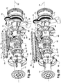
- the support 14 is formed in this case by a shaft shaft 12 and of generally cylindrical shape. Except when rotating the drum when making a tread, this drum is fixed.
- the drum comprises brackets 30 associated with the respective sectors.
- Each square is rigidly attached to the corresponding sector and has a general shape of right triangle, the largest side of the square adjacent to its right angle is the one to which the sector is attached.
- the hypotenuse of the square forms a rail or ramp 32. It has an elongated rectilinear shape, its orientation relative to the axis 12 corresponding to the above-mentioned sliding direction of the sector.
- the squares associated with the key sectors are arranged upside down compared to those associated with the vaulted sectors.
- Each square bears, in the vicinity of the right angle, a wheel 44 mounted free to rotate relative to the square around an axis perpendicular to the general radial plane of the square.
- the rollers 44 associated with the key sectors extend generally in the same plane perpendicular to the axis 12.
- Those associated with the vaulted sectors also extend in the same plane, distinct from the other plane.
- the drum also comprises sector holders 34 having at their top two shoes 36 engaged on the rail 32 so that the bracket is slidably mounted on the mains carrier.
- the pads have a female profile complementary to the male profile of the ramp.
- the drum further comprises plates 38 rigidly attached to the shaft 14 and extending radially therefrom.
- Each mains carrier is mounted mobile in radial sliding on the corresponding plate by suitable means not detailed.
- each carrier has two wheels or rollers 40, 42.
- the rollers 40 associated with the vaulted sectors are disposed at the ends of the mains holder while the rollers 42 associated with the key sectors are carried by the arms 41 of the mains door and face to the body of the latter. All the casters are rotatably mounted relative to the mains holder about an axis parallel to the axis 12.
- the drum comprises a plate 46 in the form of an axis disc 12 slidably mounted on the shaft 14 in the axial direction. It has profiled housing 48 open on the side of the brackets of the vaulted sectors all along the housing and at the end of the latter opposite the axis. The housings receive the corresponding wheels 44.
- the drum comprises a similar plate 50 associated with the wheels of the key sectors.
- the shaft 14 contains a screw 52 having two threaded zones in opposite directions. Two nuts 54 and 56 are engaged with these respective zones and rigidly connected to the respective plates 46, 50.
- the screw has at its right end on the figure 30 a clutch 58 serving as a coupling means with a drive member in rotation of the screw which has not been illustrated.
- the rotation of the screw 52 from the clutch 58 causes the sliding of the nut 54 and the plate 46 on the one hand and that in the opposite direction of the nut 56 and the plate 50 on the other hand.
- the crew formed by the plate 46 and the nut 54 drives in its axial sliding the brackets 30 and the vaulted sectors 6v. Given the ramp, this causes the displacement of the brackets and sectors in the direction inclined relative to the axis.
- the crew formed by the plate 50 and the nut 56 drives the brackets 30 and the key sectors 6c and causes them to move in the direction inclined with respect to the axis.
- the screw in a first direction of rotation, causes the approximation of the key sectors and sectors vaulted from each other in the axial direction and the increase in the diameter of the circumferential face of the drum.
- This displacement is shown by the succession of figures 30 and 31 .
- the distance of the plates causes the reduction of this diameter. This is how we adjust the diameter of the working side of the drum.
- the drum furthermore comprises two two-sided cams 60. The two faces of the cam located furthest on the right figure 28 are illustrated in Figures 26 and 27 .
- the two cams are rigidly secured to one another and rotatably mounted on the shaft 14 about the axis 12, without the possibility of sliding along the latter.
- Each biface cam comprises a disc having grooves or ramps 62, 64 on its respective faces 66, 68.
- the two cams are symmetrical to one another with respect to a plane perpendicular to the axis 12, the faces 66 being oriented towards each other.
- the grooves 62 of these faces receive the respective rollers 40 associated with the vaulted sectors.
- the grooves 64 of the other faces 68 receive those corresponding to the key sectors 6v.
- the grooves 62 are identical to each other. It is the same for the grooves 64.
- Each groove 62 has a very short section in an arc of an axis 12 contiguous to the edge of the disc and a main section in an arc, the section going closer to the axis .
- Each groove 64 comprises two sections 65, 67 of substantially the same length, both in an arc. The first 65 is located at the edge of the disc and is centered on the axis 12 while the second is close to the axis 12.
- the barrel carries a wheel 70 and a pinion 72 rigidly secured to each other and both mounted rotatably mounted relative to the barrel about the axis 12.
- the drum also comprises a pinion 74 mounted to rotate around an axis parallel to the axis 12 but distinct from the latter and carried by an arm 76 itself carried by the shaft 14.
- a shaft 77 is rigidly secured to the pinion 74 and a toothed sector 78 engaged with another toothed sector 80 rigidly secured to the cams 60.
- each ramp of the cams is made in such a way that, for a constant speed of rotation of the cam, the speed of movement of the sectors is made variable, for example progressive or lower at the end of the collapsing run. extension, to reduce jolts.
- the key sectors have under each of their lateral faces 9 a clearance or redan 82 which allows them to receive a part of the vaulted sectors after the beginning of the radial movement of the latter.
- the continuation of the movement of the two types of sectors can thus be carried out with the sectors vaults partially housed in the clearances.
- This clearance makes it possible to avoid moving the vault sectors over a too long radial stroke in the first phase and thus makes it possible to reduce the cycle times.
- the two mechanisms allowing respectively the adjustment of the diameter and the collapse, are completely independent.
- the drum 2 has eighteen sectors (6c, 6v). This number of sectors has been chosen to obtain a "discretization" of the outer surface of the smallest possible drum, in order to obtain the best possible geometrical regularity (cylindricity and continuity of the surface) over the entire range of diameter adjustment, range which extends in this case on 100 mm.
- the greater the number of sectors the more the influence of the irregularities of the circumferential surface of the drum is reduced vis-à-vis the uniformity of the tire envelope which is manufactured on it.
- the described embodiment results from a compromise between the largest number of possible sectors, the complexity to house the mechanisms for controlling the different movements of the sectors, and therefore the price.
- the mechanisms allowing during the same movement of a cam the descent of the vaulted sectors first and then simultaneously the key sectors and vaulted sectors is applicable to other types of drum and for example to that of the aforementioned application WO 2013/054051 .
Landscapes
- Engineering & Computer Science (AREA)
- Mechanical Engineering (AREA)
- Manufacturing & Machinery (AREA)
- Tyre Moulding (AREA)
- Tires In General (AREA)
Claims (11)
- Trommel (2) zum Aufbau eines Luftreifen-Mantelrohlings, die aufweist:- Sektoren (6v, 6c), die eine Umfangsseite der Trommel bilden, und- mindestens eine Nockenscheibe (60) zur Steuerung einer radialen Verschiebung der Sektoren bezüglich einer Drehachse (12) der Trommel,wobei die Nockenscheibe zwei Hauptseiten (66, 68) aufweist und so eingerichtet ist, dass eine monotone Bewegung der Nockenscheibe zunächst die radiale Verschiebung bestimmter (6v) der Sektoren aufgrund von auf ihrer ersten Seite (66) befindlichen Rampen (62) ohne Veränderung einer radialen Stellung der anderen Sektoren (6c) bewirkt, dann die radiale Verschiebung der anderen Sektoren (6c) aufgrund von auf ihrer zweiten Seite (68) befindlichen Rampen (64) bewirkt, wobei die Verschiebung aller Sektoren (6v, 6c) dann gleichzeitig ist.
- Trommel nach dem vorhergehenden Anspruch, wobei die Sektoren Sektoren (6v) eines ersten Typs und Sektoren (6c) eines zweiten Typs enthalten, die in radialer Richtung gegen die Sektoren des ersten Typs in Anlage kommen können, wobei die Nockenscheibe (60) so eingerichtet ist, dass die Sektoren des ersten Typs (6v) aufgrund der auf der ersten Seite (66) der Nockenscheibe befindlichen Rampen (62) verschoben werden, während die Sektoren (6c) des zweiten Typs aufgrund der auf der zweiten Seite (68) der Nockenscheibe befindlichen Rampen (64) verschoben werden.
- Trommel nach dem vorhergehenden Anspruch, die so eingerichtet ist, dass die Sektoren des ersten Typs (6v) nach dem Beginn ihrer Verschiebung durch die Nockenscheibe in Aussparungen (82) empfangen werden, die in den Sektoren des zweiten Typs vorgesehen sind.
- Trommel nach mindestens einem der vorhergehenden Ansprüche, wobei bestimmte der Rampen (64), die die Verschiebung bestimmter Sektoren (6c) steuern können, einen kreisbogenförmigen Abschnitt (65) koaxial zu einer Drehachse der Nockenscheibe aufweisen.
- Trommel nach mindestens einem der vorhergehenden Ansprüche, wobei es mindestens zwei Nockenscheiben (60) gibt.
- Trommel nach mindestens einem der vorhergehenden Ansprüche, wobei mindestens bestimmte der Sektoren, und vorzugsweise alle (6v, 6c), bezüglich des Trägers in einer vorbestimmten Richtung (13) nicht radial zur Drehachse (12) beweglich montiert sind und letztere schneiden.
- Trommel nach mindestens einem der vorhergehenden Ansprüche, die mindestens eine Einheit (46, 54, 50, 56) enthält, die gleitend bezüglich des Trägers in Richtung der Drehachse montiert und mit mehreren der Sektoren verbunden ist.
- Trommel nach mindestens einem der vorhergehenden Ansprüche, die so eingerichtet ist, dass die Sektoren (6v, 6c) in Umfangsrichtung aneinander grenzen.
- Trommel nach mindestens einem der vorhergehenden Ansprüche, wobei jeder Sektor zwei ebene seitliche Hauptseiten (9) aufweist, die eingerichtet sind, um gegenüber den entsprechenden Seiten der benachbarten Sektoren zu liegen zu kommen.
- Trommel nach mindestens einem der vorhergehenden Ansprüche, wobei mindestens bestimmte der Sektoren, und vorzugsweise alle (6v, 6c), eine Außenseite (10) aufweisen, die einen allgemein trapezförmigen Umriss hat.
- Verfahren zur Herstellung eines Luftreifenmantels, dadurch gekennzeichnet, dass mindestens ein Teil eines Laufstreifens eines Rohlings des Mantels auf einer Trommel (2) nach mindestens einem der vorhergehenden Ansprüche montiert wird.
Applications Claiming Priority (2)
| Application Number | Priority Date | Filing Date | Title |
|---|---|---|---|
| FR1357679A FR3009232B1 (fr) | 2013-08-01 | 2013-08-01 | Tambour de confection d'une bande de roulement muni de secteurs retractables |
| PCT/FR2014/051915 WO2015015096A1 (fr) | 2013-08-01 | 2014-07-23 | Tambour muni de secteurs mobiles pour la confection d'un pneumatique |
Publications (2)
| Publication Number | Publication Date |
|---|---|
| EP3027402A1 EP3027402A1 (de) | 2016-06-08 |
| EP3027402B1 true EP3027402B1 (de) | 2017-09-20 |
Family
ID=49378496
Family Applications (1)
| Application Number | Title | Priority Date | Filing Date |
|---|---|---|---|
| EP14759015.2A Active EP3027402B1 (de) | 2013-08-01 | 2014-07-23 | Reifenaufbautrommel mit einschiebbaren sektoren |
Country Status (6)
| Country | Link |
|---|---|
| US (1) | US10639859B2 (de) |
| EP (1) | EP3027402B1 (de) |
| CN (1) | CN105408098B (de) |
| BR (1) | BR112016001340B1 (de) |
| FR (1) | FR3009232B1 (de) |
| WO (1) | WO2015015096A1 (de) |
Families Citing this family (6)
| Publication number | Priority date | Publication date | Assignee | Title |
|---|---|---|---|---|
| FR3031695B1 (fr) * | 2015-01-16 | 2017-02-24 | Michelin & Cie | Tambour de confection d'une ebauche de pneumatique |
| NL2021086B1 (en) * | 2018-06-08 | 2019-12-13 | Vmi Holland Bv | Tire building method and tire building system, in particular for strip-winding |
| WO2020160012A1 (en) * | 2019-01-28 | 2020-08-06 | Davian Enterprises, LLC | Expandable belt and tread drum with reverse offset fingers |
| KR20230003534A (ko) | 2020-04-22 | 2023-01-06 | 윌리엄 에이. 존스 | 타이어 성형기용 숄더 어셈블리 |
| US12162234B2 (en) | 2020-05-29 | 2024-12-10 | Davian Enterprises, LLC | Transfer ring shoe and transfer ring with reduced air entrapment features |
| WO2022120117A2 (en) | 2020-12-03 | 2022-06-09 | Davian Enterprises, Llc (Dba Wyko Tire Technologies) | Expandable belt and tread drum with magnetic deck fixing |
Family Cites Families (18)
| Publication number | Priority date | Publication date | Assignee | Title |
|---|---|---|---|---|
| US1479005A (en) * | 1924-01-01 | Holding means for tire casings | ||
| US1669532A (en) * | 1923-04-19 | 1928-05-15 | Firestone Tire & Rubber Co | Collapsible core |
| US3485700A (en) * | 1966-07-20 | 1969-12-23 | Ralph F Cooper | Tire building drum |
| BR6794587D0 (pt) * | 1966-12-22 | 1973-06-12 | Pirelli | Tambor para a confeccao de carcacas de pneumaticos |
| US3779835A (en) * | 1971-06-03 | 1973-12-18 | Akron Standard Division Of Eag | Building drum |
| US3867231A (en) * | 1972-06-28 | 1975-02-18 | Goodyear Tire & Rubber | Tire building machine |
| JPS5531733B2 (de) * | 1974-06-13 | 1980-08-20 | ||
| JPS61134234A (ja) * | 1984-12-04 | 1986-06-21 | Mitsubishi Heavy Ind Ltd | ラジアルタイヤ成形用ブラダレスドラム |
| US4772351A (en) * | 1987-10-05 | 1988-09-20 | Eagle-Picher Industries, Inc. | Cam operated tire building drum |
| US5320701A (en) * | 1992-11-04 | 1994-06-14 | Illinois Tool Works Inc. | Tire building drum |
| JP3285282B2 (ja) * | 1994-09-09 | 2002-05-27 | 京三電機株式会社 | 巻線機 |
| CN2389779Y (zh) * | 1998-12-02 | 2000-08-02 | 陈宝山 | 辐撑直缩式轮胎成型装置 |
| US20030029573A1 (en) * | 2000-02-29 | 2003-02-13 | Robert Franke | Formation of tyre beads or the like |
| US6769468B2 (en) * | 2001-09-21 | 2004-08-03 | The Goodyear Tire & Rubber Company | Tire building drum having expandable center section and independently expandable bead lock assemblies in the end sections |
| CN2521029Y (zh) * | 2002-02-09 | 2002-11-20 | 天津赛象科技股份有限公司 | 一种贴合鼓 |
| KR100963503B1 (ko) * | 2008-08-18 | 2010-06-15 | (주)세화아이엠씨 | 그린타이어 성형드럼장치 |
| BRPI1014964B1 (pt) * | 2009-04-08 | 2019-10-22 | Pirelli | processo para fabricar pneus para rodas de veículo, e, aparelho para reforçar com um laço uma estrutura de ancoragem anular de um pneu para rodas de veículo. |
| FR2981293B1 (fr) * | 2011-10-14 | 2017-02-10 | Soc De Tech Michelin | Tambour de fabrication de pneumatique comprenant des secteurs mobiles |
-
2013
- 2013-08-01 FR FR1357679A patent/FR3009232B1/fr not_active Expired - Fee Related
-
2014
- 2014-07-23 US US14/908,300 patent/US10639859B2/en active Active
- 2014-07-23 EP EP14759015.2A patent/EP3027402B1/de active Active
- 2014-07-23 BR BR112016001340-9A patent/BR112016001340B1/pt active IP Right Grant
- 2014-07-23 CN CN201480042592.1A patent/CN105408098B/zh active Active
- 2014-07-23 WO PCT/FR2014/051915 patent/WO2015015096A1/fr not_active Ceased
Non-Patent Citations (1)
| Title |
|---|
| None * |
Also Published As
| Publication number | Publication date |
|---|---|
| BR112016001340A8 (pt) | 2018-01-02 |
| US20160159023A1 (en) | 2016-06-09 |
| WO2015015096A1 (fr) | 2015-02-05 |
| BR112016001340B1 (pt) | 2021-08-17 |
| CN105408098A (zh) | 2016-03-16 |
| FR3009232B1 (fr) | 2016-01-01 |
| US10639859B2 (en) | 2020-05-05 |
| BR112016001340A2 (pt) | 2017-07-25 |
| FR3009232A1 (fr) | 2015-02-06 |
| EP3027402A1 (de) | 2016-06-08 |
| CN105408098B (zh) | 2018-01-26 |
Similar Documents
| Publication | Publication Date | Title |
|---|---|---|
| EP3027402B1 (de) | Reifenaufbautrommel mit einschiebbaren sektoren | |
| EP2707204B1 (de) | Werkzeug zum positionieren eines bandes zur herstellung eines reifenrohlings und verfahren zur realisation eines reifenrohlings | |
| EP3027401B1 (de) | Reifenaufbautrommel mit beweglichen sektoren | |
| EP3113939B1 (de) | Reifenaufbautrommel | |
| EP3245052B1 (de) | Trommel zum herstellen eines reifenrohlings | |
| EP2750869B1 (de) | Reifenaufbautrommel mit beweglichen sektoren | |
| EP4313572B1 (de) | Vorrichtung zur formung eines luftreifens mit einem system zur bedingten unterstützung der drehung der flansche mit den wulsten des reifens | |
| WO2015197935A1 (fr) | Tambour de confection de pneumatique avec des secteurs cylindriques telescopiques | |
| EP3458256B1 (de) | Faltsystem zur herstellung von reifenrohlingen | |
| EP3458253B1 (de) | Verfahren und vorrichtung zur umschlagung eines reifenrohlings | |
| EP3458254B1 (de) | Aufklappsystem zur herstellung von reifenrohlingen. | |
| WO2013107980A1 (fr) | Tambour d'assemblage d'une ebauche de pneumatique presentant des elements mobiles | |
| WO2016102537A1 (fr) | Dispositif de depose d'un fil ondule sur une surface de reception | |
| FR3051391A1 (fr) | Methode de pilotage d'un procede de retroussage d'une ebauche de pneumatique | |
| FR3061071A1 (fr) | Modes de pilotage d'un procede de retroussage d'une ebauche de pneumatique |
Legal Events
| Date | Code | Title | Description |
|---|---|---|---|
| PUAI | Public reference made under article 153(3) epc to a published international application that has entered the european phase |
Free format text: ORIGINAL CODE: 0009012 |
|
| 17P | Request for examination filed |
Effective date: 20160118 |
|
| AK | Designated contracting states |
Kind code of ref document: A1 Designated state(s): AL AT BE BG CH CY CZ DE DK EE ES FI FR GB GR HR HU IE IS IT LI LT LU LV MC MK MT NL NO PL PT RO RS SE SI SK SM TR |
|
| AX | Request for extension of the european patent |
Extension state: BA ME |
|
| DAX | Request for extension of the european patent (deleted) | ||
| GRAP | Despatch of communication of intention to grant a patent |
Free format text: ORIGINAL CODE: EPIDOSNIGR1 |
|
| STAA | Information on the status of an ep patent application or granted ep patent |
Free format text: STATUS: GRANT OF PATENT IS INTENDED |
|
| INTG | Intention to grant announced |
Effective date: 20170411 |
|
| RAP1 | Party data changed (applicant data changed or rights of an application transferred) |
Owner name: COMPAGNIE GENERALE DES ETABLISSEMENTS MICHELIN |
|
| RAP1 | Party data changed (applicant data changed or rights of an application transferred) |
Owner name: COMPAGNIE GENERALE DES ETABLISSEMENTS MICHELIN |
|
| GRAS | Grant fee paid |
Free format text: ORIGINAL CODE: EPIDOSNIGR3 |
|
| GRAA | (expected) grant |
Free format text: ORIGINAL CODE: 0009210 |
|
| STAA | Information on the status of an ep patent application or granted ep patent |
Free format text: STATUS: THE PATENT HAS BEEN GRANTED |
|
| AK | Designated contracting states |
Kind code of ref document: B1 Designated state(s): AL AT BE BG CH CY CZ DE DK EE ES FI FR GB GR HR HU IE IS IT LI LT LU LV MC MK MT NL NO PL PT RO RS SE SI SK SM TR |
|
| REG | Reference to a national code |
Ref country code: GB Ref legal event code: FG4D Free format text: NOT ENGLISH |
|
| REG | Reference to a national code |
Ref country code: CH Ref legal event code: EP |
|
| REG | Reference to a national code |
Ref country code: AT Ref legal event code: REF Ref document number: 929823 Country of ref document: AT Kind code of ref document: T Effective date: 20171015 |
|
| REG | Reference to a national code |
Ref country code: IE Ref legal event code: FG4D Free format text: LANGUAGE OF EP DOCUMENT: FRENCH |
|
| REG | Reference to a national code |
Ref country code: DE Ref legal event code: R096 Ref document number: 602014014864 Country of ref document: DE |
|
| REG | Reference to a national code |
Ref country code: NL Ref legal event code: FP |
|
| PG25 | Lapsed in a contracting state [announced via postgrant information from national office to epo] |
Ref country code: FI Free format text: LAPSE BECAUSE OF FAILURE TO SUBMIT A TRANSLATION OF THE DESCRIPTION OR TO PAY THE FEE WITHIN THE PRESCRIBED TIME-LIMIT Effective date: 20170920 Ref country code: HR Free format text: LAPSE BECAUSE OF FAILURE TO SUBMIT A TRANSLATION OF THE DESCRIPTION OR TO PAY THE FEE WITHIN THE PRESCRIBED TIME-LIMIT Effective date: 20170920 Ref country code: SE Free format text: LAPSE BECAUSE OF FAILURE TO SUBMIT A TRANSLATION OF THE DESCRIPTION OR TO PAY THE FEE WITHIN THE PRESCRIBED TIME-LIMIT Effective date: 20170920 Ref country code: NO Free format text: LAPSE BECAUSE OF FAILURE TO SUBMIT A TRANSLATION OF THE DESCRIPTION OR TO PAY THE FEE WITHIN THE PRESCRIBED TIME-LIMIT Effective date: 20171220 Ref country code: LT Free format text: LAPSE BECAUSE OF FAILURE TO SUBMIT A TRANSLATION OF THE DESCRIPTION OR TO PAY THE FEE WITHIN THE PRESCRIBED TIME-LIMIT Effective date: 20170920 |
|
| REG | Reference to a national code |
Ref country code: LT Ref legal event code: MG4D |
|
| REG | Reference to a national code |
Ref country code: AT Ref legal event code: MK05 Ref document number: 929823 Country of ref document: AT Kind code of ref document: T Effective date: 20170920 |
|
| PG25 | Lapsed in a contracting state [announced via postgrant information from national office to epo] |
Ref country code: GR Free format text: LAPSE BECAUSE OF FAILURE TO SUBMIT A TRANSLATION OF THE DESCRIPTION OR TO PAY THE FEE WITHIN THE PRESCRIBED TIME-LIMIT Effective date: 20171221 Ref country code: BG Free format text: LAPSE BECAUSE OF FAILURE TO SUBMIT A TRANSLATION OF THE DESCRIPTION OR TO PAY THE FEE WITHIN THE PRESCRIBED TIME-LIMIT Effective date: 20171220 Ref country code: LV Free format text: LAPSE BECAUSE OF FAILURE TO SUBMIT A TRANSLATION OF THE DESCRIPTION OR TO PAY THE FEE WITHIN THE PRESCRIBED TIME-LIMIT Effective date: 20170920 Ref country code: RS Free format text: LAPSE BECAUSE OF FAILURE TO SUBMIT A TRANSLATION OF THE DESCRIPTION OR TO PAY THE FEE WITHIN THE PRESCRIBED TIME-LIMIT Effective date: 20170920 |
|
| PG25 | Lapsed in a contracting state [announced via postgrant information from national office to epo] |
Ref country code: CZ Free format text: LAPSE BECAUSE OF FAILURE TO SUBMIT A TRANSLATION OF THE DESCRIPTION OR TO PAY THE FEE WITHIN THE PRESCRIBED TIME-LIMIT Effective date: 20170920 Ref country code: PL Free format text: LAPSE BECAUSE OF FAILURE TO SUBMIT A TRANSLATION OF THE DESCRIPTION OR TO PAY THE FEE WITHIN THE PRESCRIBED TIME-LIMIT Effective date: 20170920 Ref country code: RO Free format text: LAPSE BECAUSE OF FAILURE TO SUBMIT A TRANSLATION OF THE DESCRIPTION OR TO PAY THE FEE WITHIN THE PRESCRIBED TIME-LIMIT Effective date: 20170920 Ref country code: ES Free format text: LAPSE BECAUSE OF FAILURE TO SUBMIT A TRANSLATION OF THE DESCRIPTION OR TO PAY THE FEE WITHIN THE PRESCRIBED TIME-LIMIT Effective date: 20170920 |
|
| PG25 | Lapsed in a contracting state [announced via postgrant information from national office to epo] |
Ref country code: SK Free format text: LAPSE BECAUSE OF FAILURE TO SUBMIT A TRANSLATION OF THE DESCRIPTION OR TO PAY THE FEE WITHIN THE PRESCRIBED TIME-LIMIT Effective date: 20170920 Ref country code: IT Free format text: LAPSE BECAUSE OF FAILURE TO SUBMIT A TRANSLATION OF THE DESCRIPTION OR TO PAY THE FEE WITHIN THE PRESCRIBED TIME-LIMIT Effective date: 20170920 Ref country code: EE Free format text: LAPSE BECAUSE OF FAILURE TO SUBMIT A TRANSLATION OF THE DESCRIPTION OR TO PAY THE FEE WITHIN THE PRESCRIBED TIME-LIMIT Effective date: 20170920 Ref country code: IS Free format text: LAPSE BECAUSE OF FAILURE TO SUBMIT A TRANSLATION OF THE DESCRIPTION OR TO PAY THE FEE WITHIN THE PRESCRIBED TIME-LIMIT Effective date: 20180120 Ref country code: AT Free format text: LAPSE BECAUSE OF FAILURE TO SUBMIT A TRANSLATION OF THE DESCRIPTION OR TO PAY THE FEE WITHIN THE PRESCRIBED TIME-LIMIT Effective date: 20170920 Ref country code: SM Free format text: LAPSE BECAUSE OF FAILURE TO SUBMIT A TRANSLATION OF THE DESCRIPTION OR TO PAY THE FEE WITHIN THE PRESCRIBED TIME-LIMIT Effective date: 20170920 |
|
| REG | Reference to a national code |
Ref country code: DE Ref legal event code: R097 Ref document number: 602014014864 Country of ref document: DE |
|
| PLBE | No opposition filed within time limit |
Free format text: ORIGINAL CODE: 0009261 |
|
| REG | Reference to a national code |
Ref country code: FR Ref legal event code: PLFP Year of fee payment: 5 |
|
| STAA | Information on the status of an ep patent application or granted ep patent |
Free format text: STATUS: NO OPPOSITION FILED WITHIN TIME LIMIT |
|
| PG25 | Lapsed in a contracting state [announced via postgrant information from national office to epo] |
Ref country code: DK Free format text: LAPSE BECAUSE OF FAILURE TO SUBMIT A TRANSLATION OF THE DESCRIPTION OR TO PAY THE FEE WITHIN THE PRESCRIBED TIME-LIMIT Effective date: 20170920 |
|
| 26N | No opposition filed |
Effective date: 20180621 |
|
| PG25 | Lapsed in a contracting state [announced via postgrant information from national office to epo] |
Ref country code: MT Free format text: LAPSE BECAUSE OF FAILURE TO SUBMIT A TRANSLATION OF THE DESCRIPTION OR TO PAY THE FEE WITHIN THE PRESCRIBED TIME-LIMIT Effective date: 20170920 |
|
| PG25 | Lapsed in a contracting state [announced via postgrant information from national office to epo] |
Ref country code: SI Free format text: LAPSE BECAUSE OF FAILURE TO SUBMIT A TRANSLATION OF THE DESCRIPTION OR TO PAY THE FEE WITHIN THE PRESCRIBED TIME-LIMIT Effective date: 20170920 |
|
| REG | Reference to a national code |
Ref country code: CH Ref legal event code: PL |
|
| GBPC | Gb: european patent ceased through non-payment of renewal fee |
Effective date: 20180723 |
|
| PG25 | Lapsed in a contracting state [announced via postgrant information from national office to epo] |
Ref country code: MC Free format text: LAPSE BECAUSE OF FAILURE TO SUBMIT A TRANSLATION OF THE DESCRIPTION OR TO PAY THE FEE WITHIN THE PRESCRIBED TIME-LIMIT Effective date: 20170920 Ref country code: LU Free format text: LAPSE BECAUSE OF NON-PAYMENT OF DUE FEES Effective date: 20180723 |
|
| REG | Reference to a national code |
Ref country code: BE Ref legal event code: MM Effective date: 20180731 |
|
| REG | Reference to a national code |
Ref country code: IE Ref legal event code: MM4A |
|
| PG25 | Lapsed in a contracting state [announced via postgrant information from national office to epo] |
Ref country code: CH Free format text: LAPSE BECAUSE OF NON-PAYMENT OF DUE FEES Effective date: 20180731 Ref country code: IE Free format text: LAPSE BECAUSE OF NON-PAYMENT OF DUE FEES Effective date: 20180723 Ref country code: GB Free format text: LAPSE BECAUSE OF NON-PAYMENT OF DUE FEES Effective date: 20180723 Ref country code: LI Free format text: LAPSE BECAUSE OF NON-PAYMENT OF DUE FEES Effective date: 20180731 |
|
| PG25 | Lapsed in a contracting state [announced via postgrant information from national office to epo] |
Ref country code: BE Free format text: LAPSE BECAUSE OF NON-PAYMENT OF DUE FEES Effective date: 20180731 |
|
| PG25 | Lapsed in a contracting state [announced via postgrant information from national office to epo] |
Ref country code: TR Free format text: LAPSE BECAUSE OF FAILURE TO SUBMIT A TRANSLATION OF THE DESCRIPTION OR TO PAY THE FEE WITHIN THE PRESCRIBED TIME-LIMIT Effective date: 20170920 |
|
| PG25 | Lapsed in a contracting state [announced via postgrant information from national office to epo] |
Ref country code: PT Free format text: LAPSE BECAUSE OF FAILURE TO SUBMIT A TRANSLATION OF THE DESCRIPTION OR TO PAY THE FEE WITHIN THE PRESCRIBED TIME-LIMIT Effective date: 20170920 |
|
| PG25 | Lapsed in a contracting state [announced via postgrant information from national office to epo] |
Ref country code: CY Free format text: LAPSE BECAUSE OF FAILURE TO SUBMIT A TRANSLATION OF THE DESCRIPTION OR TO PAY THE FEE WITHIN THE PRESCRIBED TIME-LIMIT Effective date: 20170920 Ref country code: HU Free format text: LAPSE BECAUSE OF FAILURE TO SUBMIT A TRANSLATION OF THE DESCRIPTION OR TO PAY THE FEE WITHIN THE PRESCRIBED TIME-LIMIT; INVALID AB INITIO Effective date: 20140723 Ref country code: MK Free format text: LAPSE BECAUSE OF NON-PAYMENT OF DUE FEES Effective date: 20170920 |
|
| PG25 | Lapsed in a contracting state [announced via postgrant information from national office to epo] |
Ref country code: AL Free format text: LAPSE BECAUSE OF FAILURE TO SUBMIT A TRANSLATION OF THE DESCRIPTION OR TO PAY THE FEE WITHIN THE PRESCRIBED TIME-LIMIT Effective date: 20170920 |
|
| PGFP | Annual fee paid to national office [announced via postgrant information from national office to epo] |
Ref country code: NL Payment date: 20250721 Year of fee payment: 12 |
|
| PGFP | Annual fee paid to national office [announced via postgrant information from national office to epo] |
Ref country code: DE Payment date: 20250722 Year of fee payment: 12 |
|
| PGFP | Annual fee paid to national office [announced via postgrant information from national office to epo] |
Ref country code: FR Payment date: 20250725 Year of fee payment: 12 |