EP3027788B1 - Gerät für wasserstoff und strom herstellung - Google Patents
Gerät für wasserstoff und strom herstellung Download PDFInfo
- Publication number
- EP3027788B1 EP3027788B1 EP14772266.4A EP14772266A EP3027788B1 EP 3027788 B1 EP3027788 B1 EP 3027788B1 EP 14772266 A EP14772266 A EP 14772266A EP 3027788 B1 EP3027788 B1 EP 3027788B1
- Authority
- EP
- European Patent Office
- Prior art keywords
- photoanode
- hydrogen
- water
- cathode
- membrane
- Prior art date
- Legal status (The legal status is an assumption and is not a legal conclusion. Google has not performed a legal analysis and makes no representation as to the accuracy of the status listed.)
- Active
Links
Images




Classifications
-
- C—CHEMISTRY; METALLURGY
- C25—ELECTROLYTIC OR ELECTROPHORETIC PROCESSES; APPARATUS THEREFOR
- C25B—ELECTROLYTIC OR ELECTROPHORETIC PROCESSES FOR THE PRODUCTION OF COMPOUNDS OR NON-METALS; APPARATUS THEREFOR
- C25B1/00—Electrolytic production of inorganic compounds or non-metals
- C25B1/50—Processes
- C25B1/55—Photoelectrolysis
-
- C—CHEMISTRY; METALLURGY
- C25—ELECTROLYTIC OR ELECTROPHORETIC PROCESSES; APPARATUS THEREFOR
- C25B—ELECTROLYTIC OR ELECTROPHORETIC PROCESSES FOR THE PRODUCTION OF COMPOUNDS OR NON-METALS; APPARATUS THEREFOR
- C25B1/00—Electrolytic production of inorganic compounds or non-metals
- C25B1/01—Products
- C25B1/02—Hydrogen or oxygen
- C25B1/04—Hydrogen or oxygen by electrolysis of water
-
- C—CHEMISTRY; METALLURGY
- C25—ELECTROLYTIC OR ELECTROPHORETIC PROCESSES; APPARATUS THEREFOR
- C25B—ELECTROLYTIC OR ELECTROPHORETIC PROCESSES FOR THE PRODUCTION OF COMPOUNDS OR NON-METALS; APPARATUS THEREFOR
- C25B11/00—Electrodes; Manufacture thereof not otherwise provided for
- C25B11/04—Electrodes; Manufacture thereof not otherwise provided for characterised by the material
- C25B11/051—Electrodes formed of electrocatalysts on a substrate or carrier
- C25B11/052—Electrodes comprising one or more electrocatalytic coatings on a substrate
-
- C—CHEMISTRY; METALLURGY
- C25—ELECTROLYTIC OR ELECTROPHORETIC PROCESSES; APPARATUS THEREFOR
- C25B—ELECTROLYTIC OR ELECTROPHORETIC PROCESSES FOR THE PRODUCTION OF COMPOUNDS OR NON-METALS; APPARATUS THEREFOR
- C25B13/00—Diaphragms; Spacing elements
- C25B13/04—Diaphragms; Spacing elements characterised by the material
- C25B13/08—Diaphragms; Spacing elements characterised by the material based on organic materials
-
- C—CHEMISTRY; METALLURGY
- C25—ELECTROLYTIC OR ELECTROPHORETIC PROCESSES; APPARATUS THEREFOR
- C25B—ELECTROLYTIC OR ELECTROPHORETIC PROCESSES FOR THE PRODUCTION OF COMPOUNDS OR NON-METALS; APPARATUS THEREFOR
- C25B9/00—Cells or assemblies of cells; Constructional parts of cells; Assemblies of constructional parts, e.g. electrode-diaphragm assemblies; Process-related cell features
- C25B9/17—Cells comprising dimensionally-stable non-movable electrodes; Assemblies of constructional parts thereof
- C25B9/19—Cells comprising dimensionally-stable non-movable electrodes; Assemblies of constructional parts thereof with diaphragms
-
- C—CHEMISTRY; METALLURGY
- C25—ELECTROLYTIC OR ELECTROPHORETIC PROCESSES; APPARATUS THEREFOR
- C25B—ELECTROLYTIC OR ELECTROPHORETIC PROCESSES FOR THE PRODUCTION OF COMPOUNDS OR NON-METALS; APPARATUS THEREFOR
- C25B9/00—Cells or assemblies of cells; Constructional parts of cells; Assemblies of constructional parts, e.g. electrode-diaphragm assemblies; Process-related cell features
- C25B9/17—Cells comprising dimensionally-stable non-movable electrodes; Assemblies of constructional parts thereof
- C25B9/19—Cells comprising dimensionally-stable non-movable electrodes; Assemblies of constructional parts thereof with diaphragms
- C25B9/23—Cells comprising dimensionally-stable non-movable electrodes; Assemblies of constructional parts thereof with diaphragms comprising ion-exchange membranes in or on which electrode material is embedded
-
- C—CHEMISTRY; METALLURGY
- C25—ELECTROLYTIC OR ELECTROPHORETIC PROCESSES; APPARATUS THEREFOR
- C25B—ELECTROLYTIC OR ELECTROPHORETIC PROCESSES FOR THE PRODUCTION OF COMPOUNDS OR NON-METALS; APPARATUS THEREFOR
- C25B9/00—Cells or assemblies of cells; Constructional parts of cells; Assemblies of constructional parts, e.g. electrode-diaphragm assemblies; Process-related cell features
- C25B9/50—Cells or assemblies of cells comprising photoelectrodes; Assemblies of constructional parts thereof
-
- B—PERFORMING OPERATIONS; TRANSPORTING
- B01—PHYSICAL OR CHEMICAL PROCESSES OR APPARATUS IN GENERAL
- B01J—CHEMICAL OR PHYSICAL PROCESSES, e.g. CATALYSIS OR COLLOID CHEMISTRY; THEIR RELEVANT APPARATUS
- B01J35/00—Catalysts, in general, characterised by their form or physical properties
- B01J35/30—Catalysts, in general, characterised by their form or physical properties characterised by their physical properties
- B01J35/33—Electric or magnetic properties
-
- C—CHEMISTRY; METALLURGY
- C25—ELECTROLYTIC OR ELECTROPHORETIC PROCESSES; APPARATUS THEREFOR
- C25B—ELECTROLYTIC OR ELECTROPHORETIC PROCESSES FOR THE PRODUCTION OF COMPOUNDS OR NON-METALS; APPARATUS THEREFOR
- C25B11/00—Electrodes; Manufacture thereof not otherwise provided for
- C25B11/04—Electrodes; Manufacture thereof not otherwise provided for characterised by the material
- C25B11/051—Electrodes formed of electrocatalysts on a substrate or carrier
- C25B11/073—Electrodes formed of electrocatalysts on a substrate or carrier characterised by the electrocatalyst material
- C25B11/075—Electrodes formed of electrocatalysts on a substrate or carrier characterised by the electrocatalyst material consisting of a single catalytic element or catalytic compound
- C25B11/077—Electrodes formed of electrocatalysts on a substrate or carrier characterised by the electrocatalyst material consisting of a single catalytic element or catalytic compound the compound being a non-noble metal oxide
-
- C—CHEMISTRY; METALLURGY
- C25—ELECTROLYTIC OR ELECTROPHORETIC PROCESSES; APPARATUS THEREFOR
- C25B—ELECTROLYTIC OR ELECTROPHORETIC PROCESSES FOR THE PRODUCTION OF COMPOUNDS OR NON-METALS; APPARATUS THEREFOR
- C25B11/00—Electrodes; Manufacture thereof not otherwise provided for
- C25B11/04—Electrodes; Manufacture thereof not otherwise provided for characterised by the material
- C25B11/051—Electrodes formed of electrocatalysts on a substrate or carrier
- C25B11/073—Electrodes formed of electrocatalysts on a substrate or carrier characterised by the electrocatalyst material
- C25B11/075—Electrodes formed of electrocatalysts on a substrate or carrier characterised by the electrocatalyst material consisting of a single catalytic element or catalytic compound
- C25B11/081—Electrodes formed of electrocatalysts on a substrate or carrier characterised by the electrocatalyst material consisting of a single catalytic element or catalytic compound the element being a noble metal
-
- Y—GENERAL TAGGING OF NEW TECHNOLOGICAL DEVELOPMENTS; GENERAL TAGGING OF CROSS-SECTIONAL TECHNOLOGIES SPANNING OVER SEVERAL SECTIONS OF THE IPC; TECHNICAL SUBJECTS COVERED BY FORMER USPC CROSS-REFERENCE ART COLLECTIONS [XRACs] AND DIGESTS
- Y02—TECHNOLOGIES OR APPLICATIONS FOR MITIGATION OR ADAPTATION AGAINST CLIMATE CHANGE
- Y02E—REDUCTION OF GREENHOUSE GAS [GHG] EMISSIONS, RELATED TO ENERGY GENERATION, TRANSMISSION OR DISTRIBUTION
- Y02E60/00—Enabling technologies; Technologies with a potential or indirect contribution to GHG emissions mitigation
- Y02E60/30—Hydrogen technology
- Y02E60/36—Hydrogen production from non-carbon containing sources, e.g. by water electrolysis
-
- Y—GENERAL TAGGING OF NEW TECHNOLOGICAL DEVELOPMENTS; GENERAL TAGGING OF CROSS-SECTIONAL TECHNOLOGIES SPANNING OVER SEVERAL SECTIONS OF THE IPC; TECHNICAL SUBJECTS COVERED BY FORMER USPC CROSS-REFERENCE ART COLLECTIONS [XRACs] AND DIGESTS
- Y02—TECHNOLOGIES OR APPLICATIONS FOR MITIGATION OR ADAPTATION AGAINST CLIMATE CHANGE
- Y02P—CLIMATE CHANGE MITIGATION TECHNOLOGIES IN THE PRODUCTION OR PROCESSING OF GOODS
- Y02P20/00—Technologies relating to chemical industry
- Y02P20/10—Process efficiency
- Y02P20/133—Renewable energy sources, e.g. sunlight
Definitions
- the present invention relates generally to liquid water-neutral light (e.g. solar light) hydrogen production using water molecules captured from ambient air and to an apparatus to carry out such process, for instance an energy device or light driven apparatus for hydrogen production from water vapor and sunlight and transformation of the generated hydrogen into electricity production and, more particularly to a system and method for the production of hydrogen and electricity from ambient air humidity.
- This energy device can be lightweight.
- PECs bear the promise of affordable solar hydrogen generation devices made of earth abundant metals ( Pinaud, B. et al. Energy Environ. Sci. 6, 1983-2002 (2013 )).
- Several photoelectrochemical setups performing solar water splitting without sacrificial chemicals or electrical bias have been reported ( Reece, S. Y. et al. Science 334, 645-648 (2011 ) and Maeda, K. et al. J. Am. Chem. Soc. 132, 5858-5868 (2010 )) and small solar hydrogen production systems called "artificial leaves" for practical application have been demonstrated Pinaud, B. et al. Energy Environ. Sci. 6, 1983-2002 (2013 ), Haussener, S.
- Document WO2012135862A1 shows an electrolytic cell that uses water vapour as feedstock, and includes a reduction catalyst (IrRuOx).
- IrRuOx a reduction catalyst
- Present invention provides such solution, without any water oxidation co-catalyst (e.g. IrRuOx), by a hydrogen generating device comprising at least one semiconductor photoanode which surprisingly performs the water oxidation without back reaction and without deteriorated photoefficiency.
- a hydrogen generating device comprising at least one semiconductor photoanode which surprisingly performs the water oxidation without back reaction and without deteriorated photoefficiency.
- Such liquid water-neutral sustainable energy systems eliminates the need to feed it by liquid water supply.
- Eliminating the need for liquid water supply paves the way to water-neutral sustainable energy systems.
- Present invention provides such solution, without any water oxidation co-catalyst (e.g. IrRuOx), by a hydrogen generating device comprising at least one semiconductor photoanode which surprisingly performs the water oxidation without back reaction and without deteriorated photoefficiency.
- a hydrogen generating device comprising at least one semiconductor photoanode which surprisingly performs the water oxidation without back reaction and without deteriorated photoefficiency.
- Oxygen molecules are mediators for recombination, can cause back reaction and deteriorate photoefficiency.
- Present invention in a particular embodiment concerns an apparatus for hydrogen production from ambient air humidity and light and for transformation of the generated hydrogen into electricity, comprising: at least one semiconductor photoanode which comprises macroscopic electric conducting material coated at least in part by nanoscopic electric conducting material, and characterized in that the nanoscopic electric conducting material of the photoanode is entirely coated or covered with semiconductor layer (for instance the nanoscopic electrical conductor is entirely covered by TiO2). This prevents that the high concentration of molecular oxygen stimulates a back reaction or that the oxygen molecules in the air function as mediators for recombination of electron-hole pairs generated by illumination and deteriorate this way the photoefficiency.
- the photoanode is hereby positioned to receive light and receiving ambient air.
- the apparatus comprises a self-hydrating or water capturing material of the group consisting of water capturing microporous materials and self-hydrating monolithic membrane. Furthermore this apparatus comprises at least one cathode comprising macroscopic electric conducting material coated at least in part by nanoscopic conduction material.
- the photoanode and cathode are conductively interconnected for electron flow and are further separated from molecular flow by a proton exchange membrane or a membrane electrode assembly (MEA) comprising such proton exchange membrane for the proton flow there through to the cathode.
- the cathode is under an inert gas.
- the cathode can be in a confined environment or chamber wherein the H2 which its produces is released and is and is transported from an outlet or a port.
- This apparatus can produce hydrogen from low humidity air (ambient air) and under a condition of exposure molecular oxygen (e.g. 21% present in ambient air).
- This device to improve efficiency under ambient conditions of air and sunlight further comprises an illumination controller, being a switch (illumination / non-illumination switch) to let follow in succession periods of illumination of the at least one semiconductor photoanode with periods of non-illumination (darkness) of the at least one semiconductor photoanode.
- the membrane electrode assembly (MEA) comprises incorporating hygroscopic silica. By introducing dark periods are switched with illuminations periods for instance of ca. 200-1000s of illumination high photocurrents are retained.
- the semiconductor photoanode hydrogen generating device of present invention without water oxidation co-catalyst can combine any of the illumination controllers with the hygroscopic silica comprised in the MEA.
- Present invention provides such solution, without any water oxidation co-catalyst (e.g. IrRuOx), by a hydrogen generating device comprising at least one semiconductor photoanode which surprisingly performs the water oxidation without back reaction and without deteriorated photoefficiency.
- a hydrogen generating device comprising at least one semiconductor photoanode which surprisingly performs the water oxidation without back reaction and without deteriorated photoefficiency.
- Such liquid water-neutral sustainable energy systems eliminates the need to feed it by liquid water supply. Eliminating the need for liquid water supply paves the way to water-neutral sustainable energy systems.
- the hydrogen gas is produced at the cathode side of a two-compartment photoelectrochemical cell fed with ambient air and illuminated at the photoanode.
- the photo electrochemical device of present invention does not need the combination of the two co-catalysts, water oxidation catalyst and proton reduction catalysts, for production of hydrogen gas from ambient air humidity.
- the device has an electrode architecture, which can be robust.
- This electrode architecture comprises a proton exchange membrane and electric conducting macrostructured material on which electric conducting nanostructured material is mounted or which is coated with electric conducting nanostructured material.
- the nanostructured conducting material comprises a continuous nanocoating of semiconductor oxides which is photoactive and also protects the conducting substrate from being oxidized.
- the nanoconducting material comprises proton reduction hydrogen gas generating electrocatalyst nanoparticles.
- Water adsorbing stubs composed of water adsorbing and water condensing inorganic nanoparticle aggregates are implanted in the proton exchange membrane for maintaining hydration.
- Another aspect of the invention is the hydrogen production device composed of lightweight materials and requiring no other input but ambient air and sunlight.
- the operation of the device with air instead of for instance liquid water presents another weight gain. It is especially suitable for automotive applications and for aircrafts and aerospace application.
- the cell can be run in reverse mode in the dark to produce electricity from stored hydrogen
- this device to improve efficiency under ambient conditions of air and sunlight comprises an illumination controller, such controller can be 1) an illumination intensity controller, 2) a filter to filter out visible light to reduce dehydration or heating up and/or 3) a switch (illumination / non-illumination switch) to let follow in succession periods of illumination of the at least one semiconductor photoanode with periods of non-illumination (darkness) of the at least one semiconductor photoanode.
- the membrane electrode assembly comprises incorporating hygroscopic material.
- the hydrogen generating device of present invention with semiconductor photoanode without water oxidation co-catalyst, can combine any of the illumination controllers with the hygroscopic material comprised in the MEA.
- Such an operational device that does generate hydrogen in a cathode compartment and in which a semiconductor performs the oxidation of airborne water vapor in a separate anode compartment has not yet been demonstrated
- the invention is broadly drawn to a membrane-electrode architecture in a photoelectrochemical device for production of hydrogen gas from water vapor contained in air for instance ambient air or another gas mixture using a light source such as sunlight.
- a photoelectrochemical device can be constructed as a lightweight apparatus.
- the apparatus is particular suitable for using ambient air humidity as a supply of raw material for feeding the process of hydrogen production.
- the illuminated anode While operational in a two-compartment apparatus of present invention the illuminated anode is fed with ambient air that produces pure hydrogen at the cathode compartment. While the anode is left open to ambient air, pure hydrogen gas is produced at the cathode side of dual compartment apparatus during a full day outdoor experiment under solar illumination. Providing water through the air instead of inert carrier gas entails the additional challenge of exposing the photoanode to an oxygen containing atmosphere. Oxygen molecules are mediators for recombination, can cause back reaction and deteriorate photoefficiency.
- An embodiment to optimize operation and prevent or reduce capacity of the electrodes is provide in an embodiment of present invention by self- hydrating electrodes.
- electrodes that comprise at least one self-hydrating monolithic membrane for instance a self-hydrating monolithic membrane that comprises water capturing zeolite for instance water capturing zeolite stubs.
- Typical zeolites that act as water capturing microporous materials may have various structural group (Nickel-Strunz classification) as decribed 22,23 .
- Such self-hydrating monolithic membrane-electrode architecture is as consequence well equipped for water capturing in air of limited humidity.
- a suitable photoanode for such apparatus or assembly of present invention comprises or consists of ultrathin titanium dioxide semiconductor film, conformally coated on multi-walled carbon nanotubes to favour charge separation and tolerate atmospheric oxygen.
- An object of the invention is to provide an energy device that produces hydrogen gas from a water vapor containing gas mixture using sunlight.
- the water vapor provides the H atoms for hydrogen gas production are contained in a gas mixture comprising molecular oxygen.
- This the water vapor which provides the H atoms for hydrogen gas production can for instance be contained in ambient air.
- the invention is of advantage in sych energy device is compact and capable of being easier for users to employ in practice.
- the apparatus that produces hydrogen gas from a water vapor containing gas mixture using sunlight is arranged to comprise a proton exchange membrane, macroscopic electric conducting electrode material and nanoscopic electric conducting material characterized in that the nanoscopic electric conducting material of the photoanode is entirely coated with semiconductor nanolayer.
- the energy device that produces hydrogen gas from a water vapor containing gas mixture using sunlight can also be arranged to comprise a proton exchange membrane, macroscopic electric conducting electrode material and nanoscopic electric conducting material characterized in that the nanoscopic electric conducting material of the photoanode is entirely coated with a titanium dioxide layer.
- the energy device that produces hydrogen gas from a water vapor containing gas mixture using sunlight is arranged to comprise a proton exchange membrane, macroscopic electric conducting electrode material and nanoscopic electric conducting material characterized in that the nanoscopic electric conducting material of the photoanode is entirely coated with semiconductor oxide layer with a thickness of more than 3 nm and less than 15 nm.
- the energy device that produces hydrogen gas from a water vapor containing gas mixture using sunlight can also be arranged to comprise a proton exchange membrane, macroscopic electric conducting electrode material and nanoscopic electric conducting material characterized in that the nanoscopic electric conducting material of the cathode is supporting nanosize platinum particles or is supporting Pt, Pd, Ni or alloys comprising these containing those nanosize platinum particles.
- Such multifunctional energy device is in a particular embodiments of present prepared using atomic layer deposition and plasma enhanced atomic layer deposition techniques.
- the object of the present invention is to provide a method for generating hydrogen from ambient air humidity and light as energy source.
- An assembly of an embodiment concerns a monolithic membrane-electrode architecture with a photoanode made from multi-walled carbon nanotubes grafted on carbon fibre electrode with conformal anatase TiO2 thin film coating (TiO2/MWCNT), Nafion® proton exchange membrane (PEM), and platinum-decorated MWCNTs (Pt/MWCNT) at the cathode producing hydrogen gas using the electrons and protons from the water oxidation. Electrode surfaces are provided with water adsorbing zeolite stubs.
- It comprises carbon fibre with grafted MWCNTs and thin film TiO2 coating on MWCNTs at the anode and a cathode MWCNTs with Pt nanoparticles and hydrating zeolite stubs.
- a TiO2/MWCNT photoanode after 15 h of UV illumination showed no signs of degradation.
- the carbon fiber mesh were coated with MWCNTS and comprised dense forests of the CNTs present on all sides of the carbon fiber, there were multiwall carbon nanotubes on top of a carbon fiber with a continuous conformal TiO2 coating.
- MWCNT diameters could ne 20 nm and the TiO2 film thickness ⁇ 7-10 nm.
- the Nafion® coating. had a 2.5 ⁇ m thick Nafion® coating.
- this effective architecture comprises a proton exchange membrane, such as Nafion, flanked with macroscopic electric conducting material, such as carbon paper. On the macroscopic conducting material nanoscopic conduction material is attached, such as multiwall carbon nanotubes grafted on carbon paper. These conductive elements adjacent to the proton exchange membrane are either photoanode or cathode.
- the carbon nanotubes at the photoanode are coated with a continuous layer of semiconductor, such as oxides ( e . g . TiO 2 , Fe 2 O 3 , ZnO, NaTaO 3 , WO 3 , BiVO 4 , SrTiO 3 , Cu 2 O), sulfides ( e . g .
- plasmonic nanoparticles the continuous semiconductor layer of the photoanode can be as a method for increasing solar cell efficiency by forcing more light to be absorbed.
- Silver-gold alloy nanoparticles are a typical example.
- the electric conducting multiwall carbon nanotubes are coated with platinum nanoparticles.
- the membrane-electrode assembly is mounted in a two-compartment photoelectrochemical cells.
- the cathode compartment can either be closed to accumulate the produced hydrogen, or left open, or purged with inert gas to transport and collect the produced hydrogen.
- This embodiment advantageously comprises that when the anode is fed with a hydrated gas stream, such as hydrated air, or simply ambient air without any hydration operation and the photoanode is illuminated that hydrogen is produced.
- This embodiment of the invention advantageously comprises that when electricity is needed, the illumination is interrupted and the cell converts the previously produced solar hydrogen into electricity like a fuel cell.
- Some of the techniques described above may be embodied as an apparatus according to the invention that when operational performs three tasks that otherwise would be performed by three distinguished devices: (i) a photovoltaic device to produce electricity from sunlight, (ii) an electrolyzer to electrolyze water to produce hydrogen, and a (iii) fuel cell to convert the stored solar hydrogen into electricity when needed.
- This embodiment of the invention advantageously comprises that the integration of functions minimizes space requirement which is advantageous for applications such as in the automotive sector and especially cars, trucks, trains, busses, aircrafts, spacecrafts, and off-road vehicles and energy devices.
- An additional advantage of the apparatus of present invention operation with air instead of liquid water according to the current systems represents an important weight saving.
- An additional advantage of the device according to the invention for small scale, household and automotive application is that the hydrogen can be produced at low concentration in an inert gas, such as below 4% in nitrogen. In and around the device it is unlikely that the lower explosion limit of about 4 volume % hydrogen in air will be reached, which eliminates the explosion hazard.
- Large scale systems according to the invention could be equipped with a hydrogen concentration and pressurization unit and be combined with CO 2 mitigation systems. Mixtures of solar hydrogen and carbon dioxide could then be converted into gaseous or liquid fuels such as methane, carbon monoxide, formic acid, methanol, formaldehyde, or molecules with more than 1 C-atom and liquid mixtures suitable for substitution of fossil carbon sources.
- the photoelectrochemical device comprised a graphite flow-field plate at the cathode compartment and a fused silica plate at the anode side. Both the fused-silica plate and the graphite plate contain serpentine flows providing an optimal contact with the electrode surface 13 .
- the flow of air through the anode compartment is 12.5 ml/min.
- At the cathode side either there is no flow, or a nitrogen flow is applied at 25 ml/min. Air was hydrated by bubbling through a reservoir of water at room temperature.
- the device was illuminated by means of a Xe lamp (66984, Oriel, Newport, 200 nm ⁇ ⁇ ⁇ 1000 nm) adjusted such that the incident intensity equals 100 mW/cm 2 .
- the photocurrents were recorded using a potentiostat (Versastat 4)(Princeton Applied Research, Oak Ridge, TN) and Versastudio electrochemical analysis software.
- the outlet of the cathode compartment was analyzed with a Quantitative Gas Analyzer (QGA)(Hiden Analytical, Warrington, UK).
- the electrodes consisted of conducting and chemically inert Toray paper.
- the cathode was prepared by depositing platinum on Toray paper via drop-casting of a suspension of Pt/CB and Nafion monomer in ethanol on Toray paper, followed by air drying at 60°C.
- the Pt loading was 0.03 mg/cm 2 and the Nafion coating 0.01 mg/cm 2 .
- the anode was obtained by electrophoretic deposition of commercial P25 TiO 2 on Toray paper according to the method of Boccaccini, A. et al. (J. Mater. Sci. 39, 851 - 859 (2004 )).
- a home-made electrophoresis cell was used comprising Inox sheets (AISI321) held 1.0 cm apart by a Teflon® holder.
- a circular hole in the Teflon® mask with a diameter of 1 cm ensured that an area of 0.78 cm 2 of the Toray paper was coated.
- the potential was controlled by a potentiostat (Versastat 4, Princeton Research Systems). An electric field of 10 V/cm was applied for 60 s. After deposition, the electrodes were dried in air for 24 h and, subsequently, annealed in air for 2 h at 450°C, attained at a ramping rate of 10°C/min. The deposited amount of TiO 2 was 0.5 mg/cm 2 .
- Nafion® membranes were preconditioned according to an established procedure.
- Nafion® membrane was boiled in 5% hydrogen peroxide for 1 h and then treated in alternating baths of boiling 1 M H 2 SO 4 and boiling water for 2 and 3 h, respectively. After the last treatment in boiling water, the membrane was kept in MilliQ water in the dark at room temperature. Prior to using a membrane, it was removed from the water, quickly blotted to remove bulk water and then kept in an Inox drying holder at room temperature for 24 h.
- Membrane-electrode assemblies were prepared by fixing the anode and cathode sheets on opposite sides of the pretreated Nafion® membrane, and hot-pressing between Teflon® liners at 5 MPa and 130°C for 2.5 min. After hot-pressing, the assembly was carefully removed from between the liners and allowed to cool in an Inox holder.
- Example 2 Overcoming of the oxygen problem using a membrane-electrode assembly
- a membrane-electrode assembly was prepared by grafting multiwall carbon nanotube forests on the carbon paper and coating them with a continuous layer of a TiO 2 with a thickness of at least 3 nm, and preferentially at least 5 nm and less than 15 nm for the photoanode.
- Such continuous TiO 2 layer can be achieved by Atomic Layer Deposition.
- Atomic layer deposition of TiO 2 on the grafted carbon nanotubes was performed at 100°C. Tetrakis (dimethylamido) titanium (TDMAT) (99.999% Sigma-Aldrich) and O 3 generated by an ozone generator (Yanco Industries LTD) were alternatingly pulsed into the ALD chamber at pressures of 0.3 and 0.5 mbar, respectively.
- the concentration of ozone in the flux was 145 ⁇ g/mL.
- the pulse (20 s) and pump time (40 s) were optimized to allow for a uniform coating of TiO2 along the entire length of the MWCNTs and to prevent the occurrence of chemical vapor deposition type reactions.
- 200 cycles were applied.
- the amorphous TiO 2 was crystallized to anatase by heating at 450°C.
- the photocathode was prepared by applying Plasma Enhanced Atomic Layer Deposition of platinum on supported CNT forests using (methylcyclopentadienyl)-trimethylplatinum (MeCpPtMe 3 ) precursor ( Longrie, D. et al. ECS J. Solid State Sci. Technol 1, 123-129 (2012 )).
- the photoanode and cathode were mounted on Nafion membrane as explained in Example 1.
- SEM images were obtained with a Nova NanoSEM450 (FEI).
- the samples were mounted on aluminum stubs.
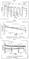
- the relative air humidity determines membrane moisture content and proton conductivity from anode to cathode compartment. Under illumination, the temperature in the anode compartment is higher than in a reference dark condition ( Figure 2 ) so relative humidity drops and water evaporates from the membrane . As a consequence, the photocurrent being representative of the hydrogen formation rate drops over time ( Figure 4 ).
- air flow in the anode compartment can be interrupted to counter dehydration ( Figure 5 ).
- the membrane Under reduced illumination intensity, the membrane is less heated and dehydration is less of a problem.
- Visible light is only little absorbed by the TiO 2 semiconductor and contributes little to hydrogen formation, but it produces heat. It can be filtered out to reduce heating up ( Figures 3 , 6,7 ).
- Hygroscopic particles dispersed in the proton exchange membrane capture moisture from the air and keep the membrane hydrated.
- Nafion with hygroscopic particles was added as a top layer on both sides of the Nafion membrane.
- inorganic materials have water adsorbing properties, such as silica and alumina gels, zeolites, clays. Capillary condensation of water can be achieved in pores with nanometer dimensions, and especially in pores with diameters from 2 to 100 nm. Such pores can be present inside individual particles, or can be created by the interstitial voids of aggregated nanoparticles.
- Silicalite zeolite nanopowder introduced into the proton exchange membrane was found to be a means of adsorbing water from the air fed into the anode compartment.
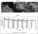
- the introduced nanopowder was found concentrated at surface stubs ( Figure 8 ).
- the hydroxylated surfaces of the zeolite nanopowder favors water adsorption and capillary condensation in the interstitial voids and concentration of water in the membrane at reduced relative humidity.
- the operation of a cell with a proton exchange membrane equipped with water adsorbing stubs at 100% and 40% relative humidity is demonstrated in Figure 9 .
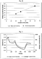
- the cell according to the present invention has high Faradaic efficiency. Within experimental error the Faradaic efficiency is close to 100%. Quantification of the hydrogen production using a membrane electrode assembly modified with hygroscopic nanopowder is shown in Figure 10 .
- the two-compartment photoelectrochemical cell according to this invention can be operated in the dark in reverse mode to produce electricity from hydrogen with air as the oxidant.
- Open circuit potentials are relatively high for such system under ambient conditions, even at low hydrogen concentrations ( Figure 11 ).
- Short circuit current is relatively low ( Figure 12 ). This current can be increased by adding noble metal catalyst nanoparticles to the anode surface which in the hydrogen production mode of the cell can serve the purpose of plasmonic antennae.
- the apparatus can be further comprising an element to switch the operation of hydrogen gas production from water vapor in the ambient air humidity to converting hydrogen into electricity.
- Example 5 Palladium as alternative catalyst for hydrogen production
- a membrane-electrode assembly according to the invention was prepared by depositing palladium on activated carbon (AC) via drop-casting of a suspension of Pd/AC and National® monomer in ethanol on Toray paper, followed by air drying at 60°C.
- the Pd loading was 0.05 mg/cm 2 and the Nafion coating 0.26 mg/cm 2 .
- the anode was obtained by electrophoretic deposition of commercial P25 TiO 2 on Toray paper according to the method of Boccaccini, A. et al. (J. Mater. Sci. 39, 851 - 859 (2004 )).
- a home-made electrophoresis cell comprising Inox sheets (AISI321) held 1.0 cm apart by a Teflon® holder. A square hole in the Teflon® mask with dimensions of 2.5 x 2.5 cm ensured that an area of 6.25 cm 2 of the Toray paper was coated. The potential was controlled by a potentiostat (Versastat 4, Princeton Research Systems). An electric field of 10 V/cm was applied for 45 s. After deposition, the electrodes were dried in air for 24 h and, subsequently, annealed in air for 2 h at 450°C, attained at a ramping rate of 10°C/min. The deposited amount of TiO 2 was 0.672 mg/cm 2 .
- Nafion 117® membranes were preconditioned according to an established procedure. Nafion® membrane was boiled in 5% hydrogen peroxide for 1 h and then treated in alternating baths of boiling 1 M H 2 SO 4 and boiling water for 2 and 3 h, respectively. After the last treatment in boiling water, the membrane was kept in MilliQ water in the dark at room temperature. Prior to using a membrane, it was removed from the water, quickly blotted to remove bulk water and then kept in an Inox drying holder at room temperature for 24 h.
- Membrane-electrode assemblies were prepared by fixing the anode and cathode sheets on opposite sides of the pretreated Nafion® membrane, placing a sandwich layer of Nafion® on top of the anode, and hot-pressing the assembly between Teflon® liners at 5 MPa and 130°C for 2.5 min. After hot-pressing, the assembly was carefully removed from between the liners and allowed to cool in an Inox holder.
- Figure 13 shows the result of a photoelectrochemical experiment that was run using this membrane-electrode assembly according to the invention, and using an inert nitrogen gas to introduce water vapor at the anode.
- the transferred electrons and produced hydrogen are shown in function of the elapsed time. It is clear that hydrogen production follows the electron transfer.
- the photocurrent in this experiment showed an overshoot of 192 ⁇ A/cm 2 and after 1h a photo current of 28.8 ⁇ A/cm 2 was observed.
- Example 6 Design of the membrane-electrode assembly.
- a design of the monolithic membrane-electrode assembly of an embodiment of present invention for performing solar hydrogen production from airborne water molecules is presented.
- Proton conducting membranes such as Nafion® were be convenient for separating the two electrode compartments and to collect the produced hydrogen gas separately.
- anode to cathode proton transport distance is made very short and efficient.
- Our strategy to minimize the detrimental impact of oxygen consisted of using multi-walled carbon nanotube (MWCNT) supports on a carbon fibre electrode as electrically conducting cores, and applying an ultrathin semiconducting TiO 2 shell to keep hole and electron transport distances minimal. Photogenerated electrons are efficiently extracted by the MWCNT forests and transported to the carbon fibre back contact.
- MWCNT multi-walled carbon nanotube
- TiO 2 thin film's crystal quality and electrical contact with the MWCNTs are of key importance.
- the presence of multiple grain boundaries in TiO 2 semiconductor is detrimental to charge transport because photogenerated carriers are scattered or trapped leading to recombination ( Tschernich, Rudy W. (1992). Zeolites of the World. Geoscience Press. p. 563 ).
- Atomic Layer Deposition (ALD) is the method of choice to prepare high quality uniform TiO 2 thin films ( First, E. L.; Gounaris, C. E.; Wei, J.; Floudas, C. A. (2011). "Computational characterization of zeolite porous networks: An automated approach”. Physical Chemistry Chemical Physics 13 (38): 17339-17358 ).
- ALD is characterized by the alternate exposure of the surface to a chemical precursor with self-limiting surface reactions followed by hydrolysis and oxidation, producing films with accurate thickness control, excellent conformality, and uniformity over large areas.
- the as-deposited about 10 nm thick conformal amorphous TiO 2 coating on the MWCNTs was crystallized to anatase by heating at 550 °C for 3 h under air.
- Thermogravimetric analysis, Raman spectroscopy and high-resolution scanning electron microscopy revealed that MWCNTs were preserved inside the anatase TiO 2 nanotubes ( Fig. 13 ).
- For the cathode a well-dispersed platinum nanophase was deposited on the MWCNTs using ALD.
- the small size and monodispersity of the deposited platinum nanoparticles ensured high availability of catalytic surface for hydrogen production, despite a low Pt loading of 13 ⁇ g cm -2 .
- the functionality of the membrane-electrode architecture was further enhanced by covering the MWCNT/carbon fibre electrodes with an additional surface layer of Nafion® ( Fig. 14 ).
- This layer provides proton conductivity and eliminates the need of a liquid electrolyte.
- Nafion® requires a high degree of hydration for proton conductivity, which can be problematic in ambient air at limited relative humidity (RH).
- Zeolites are known for their excellent water adsorbing properties (Auerbach, S. M., Carrado, K. A. & Dutta, P. K. Handbook of Zeolite Science and Technology. CRC Press (2003)).
- a zeolite devoid of alkali and alkaline earth metal cations was selected to avoid cation exchange with Nafion®.
- Silicalite nanopowder 25 was embedded in the superficial Nafion® layers of the membrane-electrode assembly.
- the zeolite was found concentrated as surface stubs.
- N 2 gas flow was humidified with H 2 18 O and fed to the photoanode compartment.
- 36 O 2 formation was detected under illumination, confirming occurrence of water oxidation.
- Formation of 34 O 2 was detected as well, since the membrane contained residual H 2 16 O.
- 32 O 2 formation out of H 2 16 O was likely to occur as well, but could not be quantified due to background signal.
- the Faradaic efficiency for 36 O 2 was 53%. Adding the contribution of 34 O 2 , the Faradaic efficiency was around 85%, and probably could have been even better if 32 O 2 formation was accounted for.
- the close to 100% Faradaic efficiency for both oxygen and hydrogen confirms the photoelectrochemical nature of overall water splitting in our PEC cell.
- Example 8 Operation under solar illumination.
- the stability of PEC cell performance was investigated by leaving the anode compartment open to ambient air (60% relative humidity at 25 °C) and illuminating with simulated sunlight for 24 h. Prior to the experiment, the cathode compartment was flushed with dry nitrogen gas and sealed. The photocurrent gradually increased and reached a steady 5.5 ⁇ A cm -2 . Interruption of the illumination caused the current to return to very low values ( ⁇ 50 nA cm -2 ) confirming the photoelectrochemical nature of the process.
Landscapes
- Chemical & Material Sciences (AREA)
- Engineering & Computer Science (AREA)
- Chemical Kinetics & Catalysis (AREA)
- Electrochemistry (AREA)
- Materials Engineering (AREA)
- Metallurgy (AREA)
- Organic Chemistry (AREA)
- Inorganic Chemistry (AREA)
- Electrolytic Production Of Non-Metals, Compounds, Apparatuses Therefor (AREA)
- Electrodes For Compound Or Non-Metal Manufacture (AREA)
Claims (15)
- Einrichtung zur Wasserstoffherstellung aus Feuchtigkeit von Umgebungsluft und Licht und zur Umwandlung des erzeugten Wasserstoffs in Strom, umfassend: mindestens eine Halbleiter-Photoanode, umfassend elektrisch leitendes makroskopisches Material, das mindestens teilweise durch elektrisch leitendes nanoskopisches Material überzogen ist, wobei das elektrisch leitende nanoskopische Material der Photoanode vollständig mit einer Halbleiterschicht überzogen ist und wobei die Photoanode positioniert ist, um Licht aufzunehmen und um Umgebungsluft aufzunehmen, weiterhin umfassend mindestens eine Kathode, umfassend elektrisch leitendes makroskopisches Material, das mindestens teilweise durch nanoskopisches Leitmaterial überzogen ist, wobei Photoanode und Kathode für Elektronenwanderung leitend miteinander verbunden sind und weiter durch eine Protonenaustauschmembran getrennt sind, eine Membranelektrodenanordnung (MEA) bildend, umfassend solche Protonenaustauschmembran für die Protonenwanderung dadurch zur Kathode und wobei die Membranelektrodenanordnung ein selbst-hydrierendes oder wasserbindendes Material der Gruppe bestehend aus wasserbindendem mikroporösem Material und selbsthydrierender monolithischer Membran umfasst, wobei die Einrichtung dadurch gekennzeichnet ist, dass sie weiter eine Beleuchtungssteuerung umfasst, wobei die Steuerung ein Schalter ist, der konfiguriert ist, um Beleuchtungsperioden der mindestens einen Halbleiter-Photoanode und Nichtbeleuchtungsperioden der mindestens einen Halbleiter-Photoanode aufeinander folgen zu lassen.
- Einrichtung nach Anspruch 1, wobei die Halbleiterschicht eine Halbleiteroxidschicht oder eine Halbleiternanoschicht ist.
- Einrichtung nach einem der vorstehenden Ansprüche, wobei die Membranelektrodenanordnung hygroskopische Nanopartikelaggregate umfasst.
- Einrichtung nach einem der vorstehenden Ansprüche, dadurch gekennzeichnet, dass die mindestens eine Kathode in einer begrenzten Umgebung, Fach oder einer Kammer ist, umfassend einen Auslass zum Freisetzen oder Extrahieren von an der Kathode hergestelltem H2.
- Einrichtung nach Anspruch 2, dadurch gekennzeichnet, dass die Halbleiteroxidschicht Titandioxid umfasst.
- Einrichtung nach einem der vorstehenden Ansprüche, wobei die Halbleiterschicht eine Halbleiternanoschicht ist und diese Überzugsnanoschicht eine Dicke von mehr als 3 nm und weniger als 15 nm aufweist.
- Einrichtung nach einem der vorstehenden Ansprüche, dadurch gekennzeichnet, dass das elektrisch leitende nanoskopische Material Kohlenstoff-Nanoröhren umfasst, die weiter mit einer durchgehenden Schicht eines Halbleiters der Gruppe der Oxide bestehend aus TiO2, Fe2O3, ZnO, NaTaO3, WO3, BiVO4, SrTiO3, Cu2O oder der Gruppe von Sulfiden bestehend aus CdS und ZnS) oder der Gruppe von Nitriden bestehend aus .GaN und TaON oder aus ihren Kombinationen überzogen sind.
- Einrichtung nach Anspruch 7, dadurch gekennzeichnet, dass plasmonische Nanopartikel und insbesondere Silber-Gold-Legierungspartikel auf der durchgehenden Schicht des Halbleiters an der Photoanode abgelagert sind.
- Einrichtung nach einem der vorstehenden Ansprüche, dadurch gekennzeichnet, dass katalytische Platinpartikel mit Nanogröße auf dem elektrisch leitenden nanoskopischen Material der Kathode abgelagert sind.
- Einrichtung nach einem der vorstehenden Ansprüche, dadurch gekennzeichnet, dass sie ohne jeglichen Wasseroxidations-Cokatalysator, wie IrRuOx, ist.
- Einrichtung nach einem der vorstehenden Ansprüche, dadurch gekennzeichnet, dass die Membranelektrodenanordnung in einer zweifächerigen photoelektrochemischen Zelle montiert ist.
- Einrichtung nach einem der vorstehenden Ansprüche, dadurch gekennzeichnet, dass das Kathodenfach geschlossen ist, um den hergestellten Wasserstoff anzuhäufen.
- Einrichtung nach einem der vorstehenden Ansprüche, dadurch gekennzeichnet, dass die Kathode eine Photokathode ist.
- Verfahren zum Betrieb der Einrichtung nach einem der vorstehenden Ansprüche 1 bis 13 durch Einführen von Photoanoden-Nichtbeleuchtungsperioden (dunkle Perioden) gewechselt mit Photoanoden-Beleuchtungsperioden der Beleuchtung, um verbesserte Wasserstoffherstellungsraten zu erzielen.
- Verfahren nach Anspruch 14, wobei die Einrichtung Wasserstoffgas aus einem Wasserdampf, der eine Gasmischung enthält, unter Verwendung von Solarenergie während der Photoanoden-Beleuchtungsperioden herstellt und das auf Anfrage während der dunklen Perioden Wasserstoff in Strom verwandelt.
Priority Applications (1)
| Application Number | Priority Date | Filing Date | Title |
|---|---|---|---|
| EP19179298.5A EP3663437B1 (de) | 2013-07-30 | 2014-07-25 | Vorrichtung zur wasserstoff- und elektrizitätserzeugung |
Applications Claiming Priority (4)
| Application Number | Priority Date | Filing Date | Title |
|---|---|---|---|
| US201361860139P | 2013-07-30 | 2013-07-30 | |
| US201361861279P | 2013-08-01 | 2013-08-01 | |
| GBGB1405671.7A GB201405671D0 (en) | 2014-03-28 | 2014-03-28 | Device for hydrogen and electricity production |
| PCT/BE2014/000036 WO2015013776A1 (en) | 2013-07-30 | 2014-07-25 | Device for hydrogen and electricity production from water vapour and light |
Related Child Applications (1)
| Application Number | Title | Priority Date | Filing Date |
|---|---|---|---|
| EP19179298.5A Division EP3663437B1 (de) | 2013-07-30 | 2014-07-25 | Vorrichtung zur wasserstoff- und elektrizitätserzeugung |
Publications (2)
| Publication Number | Publication Date |
|---|---|
| EP3027788A1 EP3027788A1 (de) | 2016-06-08 |
| EP3027788B1 true EP3027788B1 (de) | 2019-06-12 |
Family
ID=50737663
Family Applications (2)
| Application Number | Title | Priority Date | Filing Date |
|---|---|---|---|
| EP14772266.4A Active EP3027788B1 (de) | 2013-07-30 | 2014-07-25 | Gerät für wasserstoff und strom herstellung |
| EP19179298.5A Active EP3663437B1 (de) | 2013-07-30 | 2014-07-25 | Vorrichtung zur wasserstoff- und elektrizitätserzeugung |
Family Applications After (1)
| Application Number | Title | Priority Date | Filing Date |
|---|---|---|---|
| EP19179298.5A Active EP3663437B1 (de) | 2013-07-30 | 2014-07-25 | Vorrichtung zur wasserstoff- und elektrizitätserzeugung |
Country Status (4)
| Country | Link |
|---|---|
| EP (2) | EP3027788B1 (de) |
| ES (1) | ES2744877T3 (de) |
| GB (1) | GB201405671D0 (de) |
| WO (1) | WO2015013776A1 (de) |
Families Citing this family (6)
| Publication number | Priority date | Publication date | Assignee | Title |
|---|---|---|---|---|
| JP6497590B2 (ja) * | 2015-02-03 | 2019-04-10 | パナソニックIpマネジメント株式会社 | 水の分解方法、水分解装置および酸素生成用のアノード電極 |
| WO2017190202A1 (en) * | 2016-05-04 | 2017-11-09 | Katholieke Unversiteit Leuven | Hydrogen producing apparatus |
| CN108982564B (zh) * | 2018-08-17 | 2019-12-31 | 南京航空航天大学 | 一种水渣xrf定量分析的方法 |
| CN111668525B (zh) * | 2019-03-06 | 2021-10-12 | 清华大学 | 自充电储能装置 |
| CN113745609B (zh) * | 2021-10-11 | 2023-12-19 | 哈尔滨工业大学(深圳) | 一种从空气中取水的自产氢发电装置 |
| CN116497380B (zh) * | 2022-01-18 | 2025-09-30 | 四川大学 | 一种空气制氢方法及系统 |
Family Cites Families (3)
| Publication number | Priority date | Publication date | Assignee | Title |
|---|---|---|---|---|
| US7691514B2 (en) * | 2003-11-07 | 2010-04-06 | The Regents Of The University Of California | Polymer-zeolite nanocomposite membranes for proton-exchange-membrane fuel cells |
| US7993791B2 (en) * | 2005-10-26 | 2011-08-09 | Nanotek Instruments, Inc. | Self-humidifying proton exchange membrane, membrane-electrode assembly, and fuel cell |
| EP2694702A4 (de) * | 2011-04-01 | 2014-10-15 | California Inst Of Techn | Protonenaustauschmembran-elektrolyse mit wasserdampf als ausgangsmaterial |
-
2014
- 2014-03-28 GB GBGB1405671.7A patent/GB201405671D0/en not_active Ceased
- 2014-07-25 EP EP14772266.4A patent/EP3027788B1/de active Active
- 2014-07-25 EP EP19179298.5A patent/EP3663437B1/de active Active
- 2014-07-25 ES ES14772266T patent/ES2744877T3/es active Active
- 2014-07-25 WO PCT/BE2014/000036 patent/WO2015013776A1/en not_active Ceased
Non-Patent Citations (1)
| Title |
|---|
| None * |
Also Published As
| Publication number | Publication date |
|---|---|
| ES2744877T3 (es) | 2020-02-26 |
| EP3663437A1 (de) | 2020-06-10 |
| EP3663437B1 (de) | 2021-09-01 |
| GB201405671D0 (en) | 2014-05-14 |
| WO2015013776A1 (en) | 2015-02-05 |
| EP3027788A1 (de) | 2016-06-08 |
Similar Documents
| Publication | Publication Date | Title |
|---|---|---|
| Ren et al. | In situ fabrication of robust cocatalyst‐free CdS/g‐C3N4 2D–2D step‐scheme heterojunctions for highly active H2 evolution | |
| Wang et al. | Phase‐modulation of iron/nickel phosphides nanocrystals “armored” with porous P‐doped carbon and anchored on P‐doped graphene nanohybrids for enhanced overall water splitting | |
| Miao et al. | Synergy of Ni nanoclusters and single atom site: size effect on the performance of electrochemical CO2 reduction reaction and rechargeable Zn− CO2 batteries | |
| EP3663437B1 (de) | Vorrichtung zur wasserstoff- und elektrizitätserzeugung | |
| Rongé et al. | Air-based photoelectrochemical cell capturing water molecules from ambient air for hydrogen production | |
| Wang et al. | Fullerene‐buffered electron shuttle of Ru/RuO2 with switchable active sites enables robust and efficient bifunctional alkaline water electrolysis | |
| Xu et al. | NH2-MIL-125 (Ti)/graphitic carbon nitride heterostructure decorated with NiPd co-catalysts for efficient photocatalytic hydrogen production | |
| Lee et al. | Low-coordinated surface atoms of CuPt alloy cocatalysts on TiO 2 for enhanced photocatalytic conversion of CO 2 | |
| Gu et al. | Water reduction by a p-GaInP2 photoelectrode stabilized by an amorphous TiO2 coating and a molecular cobalt catalyst | |
| Mao et al. | Selected nanotechnologies for renewable energy applications | |
| CN103534202B (zh) | 光催化剂、氢生成装置及能量系统 | |
| Wen et al. | Fabricating the robust g-C3N4 nanosheets/carbons/NiS multiple heterojunctions for enhanced photocatalytic H2 generation: an insight into the trifunctional roles of nanocarbons | |
| Mishra et al. | Architecture and kinetic studies of photocatalytic H2O2 generation and H2 evolution through regulation of spatial charge transfer via Z-scheme path over a (001) facet engineered TiO2@ MXene/B-g-C3N4 ternary hybrid | |
| Pan et al. | Enhanced visible-light-driven photocatalytic H2 evolution from water on noble-metal-free CdS-nanoparticle-dispersed Mo2C@ C nanospheres | |
| Dubey et al. | Synthesis of reduced graphene oxide–TiO2 nanoparticle composite systems and its application in hydrogen production | |
| Ampelli et al. | Synthesis of solar fuels by a novel photoelectrocatalytic approach | |
| Ding et al. | Nitrogen-doped Ti3C2 MXene quantum dots/1D CdS nanorod heterostructure photocatalyst of highly efficient hydrogen evolution | |
| Sun et al. | Synergistic enhancement of H2 and CH4 evolution by CO2 photoreduction in water with reduced graphene oxide–bismuth monoxide quantum dot catalyst | |
| Li et al. | Ascorbic acid-induced structural defect in photocatalytic graphitic carbon nitride to boost H2O2 fuel cell performance | |
| Ampelli et al. | The use of a solar photoelectrochemical reactor for sustainable production of energy | |
| Wang et al. | Suppression of carbon monoxide poisoning in proton exchange membrane fuel cells via gold nanoparticle/titania ultrathin film heterogeneous catalysts | |
| de Brito et al. | Turning carbon dioxide into fuel concomitantly to the photoanode-driven process of organic pollutant degradation by photoelectrocatalysis | |
| Cai et al. | Scalable one-pot synthesis of porous 0D/2D C3N4 nanocomposites for efficient visible-light driven photocatalytic hydrogen evolution | |
| Takakura et al. | Water splitting using a three-dimensional plasmonic photoanode with titanium dioxide nano-tunnels | |
| Nguyen et al. | Plasmonic titanium nitride/g-C3N4 with inherent interface facilitates photocatalytic CO2 reduction |
Legal Events
| Date | Code | Title | Description |
|---|---|---|---|
| PUAI | Public reference made under article 153(3) epc to a published international application that has entered the european phase |
Free format text: ORIGINAL CODE: 0009012 |
|
| 17P | Request for examination filed |
Effective date: 20160229 |
|
| AK | Designated contracting states |
Kind code of ref document: A1 Designated state(s): AL AT BE BG CH CY CZ DE DK EE ES FI FR GB GR HR HU IE IS IT LI LT LU LV MC MK MT NL NO PL PT RO RS SE SI SK SM TR |
|
| AX | Request for extension of the european patent |
Extension state: BA ME |
|
| DAX | Request for extension of the european patent (deleted) | ||
| STAA | Information on the status of an ep patent application or granted ep patent |
Free format text: STATUS: EXAMINATION IS IN PROGRESS |
|
| 17Q | First examination report despatched |
Effective date: 20180209 |
|
| RAP1 | Party data changed (applicant data changed or rights of an application transferred) |
Owner name: KATHOLIEKE UNIVERSITEIT LEUVEN |
|
| RIN1 | Information on inventor provided before grant (corrected) |
Inventor name: MARTENS, JOHAN Inventor name: BOSSEREZ, TOM Inventor name: RONGE, JAN |
|
| GRAP | Despatch of communication of intention to grant a patent |
Free format text: ORIGINAL CODE: EPIDOSNIGR1 |
|
| STAA | Information on the status of an ep patent application or granted ep patent |
Free format text: STATUS: GRANT OF PATENT IS INTENDED |
|
| RIC1 | Information provided on ipc code assigned before grant |
Ipc: C25B 1/00 20060101AFI20181119BHEP Ipc: C25B 11/04 20060101ALI20181119BHEP Ipc: C25B 15/08 20060101ALI20181119BHEP Ipc: C25B 11/12 20060101ALI20181119BHEP Ipc: B01J 35/00 20060101ALI20181119BHEP |
|
| INTG | Intention to grant announced |
Effective date: 20181212 |
|
| GRAS | Grant fee paid |
Free format text: ORIGINAL CODE: EPIDOSNIGR3 |
|
| GRAA | (expected) grant |
Free format text: ORIGINAL CODE: 0009210 |
|
| STAA | Information on the status of an ep patent application or granted ep patent |
Free format text: STATUS: THE PATENT HAS BEEN GRANTED |
|
| RIN1 | Information on inventor provided before grant (corrected) |
Inventor name: RONGE, JAN Inventor name: BOSSEREZ, TOM Inventor name: MARTENS, JOHAN |
|
| AK | Designated contracting states |
Kind code of ref document: B1 Designated state(s): AL AT BE BG CH CY CZ DE DK EE ES FI FR GB GR HR HU IE IS IT LI LT LU LV MC MK MT NL NO PL PT RO RS SE SI SK SM TR |
|
| REG | Reference to a national code |
Ref country code: GB Ref legal event code: FG4D |
|
| REG | Reference to a national code |
Ref country code: CH Ref legal event code: EP |
|
| REG | Reference to a national code |
Ref country code: AT Ref legal event code: REF Ref document number: 1142643 Country of ref document: AT Kind code of ref document: T Effective date: 20190615 |
|
| REG | Reference to a national code |
Ref country code: DE Ref legal event code: R096 Ref document number: 602014048248 Country of ref document: DE |
|
| REG | Reference to a national code |
Ref country code: IE Ref legal event code: FG4D |
|
| REG | Reference to a national code |
Ref country code: NL Ref legal event code: FP |
|
| REG | Reference to a national code |
Ref country code: LT Ref legal event code: MG4D |
|
| PG25 | Lapsed in a contracting state [announced via postgrant information from national office to epo] |
Ref country code: SE Free format text: LAPSE BECAUSE OF FAILURE TO SUBMIT A TRANSLATION OF THE DESCRIPTION OR TO PAY THE FEE WITHIN THE PRESCRIBED TIME-LIMIT Effective date: 20190612 Ref country code: NO Free format text: LAPSE BECAUSE OF FAILURE TO SUBMIT A TRANSLATION OF THE DESCRIPTION OR TO PAY THE FEE WITHIN THE PRESCRIBED TIME-LIMIT Effective date: 20190912 Ref country code: LT Free format text: LAPSE BECAUSE OF FAILURE TO SUBMIT A TRANSLATION OF THE DESCRIPTION OR TO PAY THE FEE WITHIN THE PRESCRIBED TIME-LIMIT Effective date: 20190612 Ref country code: HR Free format text: LAPSE BECAUSE OF FAILURE TO SUBMIT A TRANSLATION OF THE DESCRIPTION OR TO PAY THE FEE WITHIN THE PRESCRIBED TIME-LIMIT Effective date: 20190612 Ref country code: FI Free format text: LAPSE BECAUSE OF FAILURE TO SUBMIT A TRANSLATION OF THE DESCRIPTION OR TO PAY THE FEE WITHIN THE PRESCRIBED TIME-LIMIT Effective date: 20190612 Ref country code: AL Free format text: LAPSE BECAUSE OF FAILURE TO SUBMIT A TRANSLATION OF THE DESCRIPTION OR TO PAY THE FEE WITHIN THE PRESCRIBED TIME-LIMIT Effective date: 20190612 |
|
| PG25 | Lapsed in a contracting state [announced via postgrant information from national office to epo] |
Ref country code: RS Free format text: LAPSE BECAUSE OF FAILURE TO SUBMIT A TRANSLATION OF THE DESCRIPTION OR TO PAY THE FEE WITHIN THE PRESCRIBED TIME-LIMIT Effective date: 20190612 Ref country code: GR Free format text: LAPSE BECAUSE OF FAILURE TO SUBMIT A TRANSLATION OF THE DESCRIPTION OR TO PAY THE FEE WITHIN THE PRESCRIBED TIME-LIMIT Effective date: 20190913 Ref country code: BG Free format text: LAPSE BECAUSE OF FAILURE TO SUBMIT A TRANSLATION OF THE DESCRIPTION OR TO PAY THE FEE WITHIN THE PRESCRIBED TIME-LIMIT Effective date: 20190912 Ref country code: LV Free format text: LAPSE BECAUSE OF FAILURE TO SUBMIT A TRANSLATION OF THE DESCRIPTION OR TO PAY THE FEE WITHIN THE PRESCRIBED TIME-LIMIT Effective date: 20190612 |
|
| REG | Reference to a national code |
Ref country code: AT Ref legal event code: MK05 Ref document number: 1142643 Country of ref document: AT Kind code of ref document: T Effective date: 20190612 |
|
| PG25 | Lapsed in a contracting state [announced via postgrant information from national office to epo] |
Ref country code: SK Free format text: LAPSE BECAUSE OF FAILURE TO SUBMIT A TRANSLATION OF THE DESCRIPTION OR TO PAY THE FEE WITHIN THE PRESCRIBED TIME-LIMIT Effective date: 20190612 Ref country code: EE Free format text: LAPSE BECAUSE OF FAILURE TO SUBMIT A TRANSLATION OF THE DESCRIPTION OR TO PAY THE FEE WITHIN THE PRESCRIBED TIME-LIMIT Effective date: 20190612 Ref country code: AT Free format text: LAPSE BECAUSE OF FAILURE TO SUBMIT A TRANSLATION OF THE DESCRIPTION OR TO PAY THE FEE WITHIN THE PRESCRIBED TIME-LIMIT Effective date: 20190612 Ref country code: RO Free format text: LAPSE BECAUSE OF FAILURE TO SUBMIT A TRANSLATION OF THE DESCRIPTION OR TO PAY THE FEE WITHIN THE PRESCRIBED TIME-LIMIT Effective date: 20190612 Ref country code: CZ Free format text: LAPSE BECAUSE OF FAILURE TO SUBMIT A TRANSLATION OF THE DESCRIPTION OR TO PAY THE FEE WITHIN THE PRESCRIBED TIME-LIMIT Effective date: 20190612 Ref country code: PT Free format text: LAPSE BECAUSE OF FAILURE TO SUBMIT A TRANSLATION OF THE DESCRIPTION OR TO PAY THE FEE WITHIN THE PRESCRIBED TIME-LIMIT Effective date: 20191014 |
|
| REG | Reference to a national code |
Ref country code: ES Ref legal event code: FG2A Ref document number: 2744877 Country of ref document: ES Kind code of ref document: T3 Effective date: 20200226 |
|
| PG25 | Lapsed in a contracting state [announced via postgrant information from national office to epo] |
Ref country code: SM Free format text: LAPSE BECAUSE OF FAILURE TO SUBMIT A TRANSLATION OF THE DESCRIPTION OR TO PAY THE FEE WITHIN THE PRESCRIBED TIME-LIMIT Effective date: 20190612 Ref country code: IS Free format text: LAPSE BECAUSE OF FAILURE TO SUBMIT A TRANSLATION OF THE DESCRIPTION OR TO PAY THE FEE WITHIN THE PRESCRIBED TIME-LIMIT Effective date: 20191012 Ref country code: IT Free format text: LAPSE BECAUSE OF FAILURE TO SUBMIT A TRANSLATION OF THE DESCRIPTION OR TO PAY THE FEE WITHIN THE PRESCRIBED TIME-LIMIT Effective date: 20190612 |
|
| REG | Reference to a national code |
Ref country code: DE Ref legal event code: R097 Ref document number: 602014048248 Country of ref document: DE |
|
| PG25 | Lapsed in a contracting state [announced via postgrant information from national office to epo] |
Ref country code: MC Free format text: LAPSE BECAUSE OF FAILURE TO SUBMIT A TRANSLATION OF THE DESCRIPTION OR TO PAY THE FEE WITHIN THE PRESCRIBED TIME-LIMIT Effective date: 20190612 Ref country code: TR Free format text: LAPSE BECAUSE OF FAILURE TO SUBMIT A TRANSLATION OF THE DESCRIPTION OR TO PAY THE FEE WITHIN THE PRESCRIBED TIME-LIMIT Effective date: 20190612 |
|
| PLBE | No opposition filed within time limit |
Free format text: ORIGINAL CODE: 0009261 |
|
| STAA | Information on the status of an ep patent application or granted ep patent |
Free format text: STATUS: NO OPPOSITION FILED WITHIN TIME LIMIT |
|
| PG25 | Lapsed in a contracting state [announced via postgrant information from national office to epo] |
Ref country code: PL Free format text: LAPSE BECAUSE OF FAILURE TO SUBMIT A TRANSLATION OF THE DESCRIPTION OR TO PAY THE FEE WITHIN THE PRESCRIBED TIME-LIMIT Effective date: 20190612 Ref country code: DK Free format text: LAPSE BECAUSE OF FAILURE TO SUBMIT A TRANSLATION OF THE DESCRIPTION OR TO PAY THE FEE WITHIN THE PRESCRIBED TIME-LIMIT Effective date: 20190612 |
|
| 26N | No opposition filed |
Effective date: 20200313 |
|
| PG25 | Lapsed in a contracting state [announced via postgrant information from national office to epo] |
Ref country code: IS Free format text: LAPSE BECAUSE OF FAILURE TO SUBMIT A TRANSLATION OF THE DESCRIPTION OR TO PAY THE FEE WITHIN THE PRESCRIBED TIME-LIMIT Effective date: 20200224 Ref country code: SI Free format text: LAPSE BECAUSE OF FAILURE TO SUBMIT A TRANSLATION OF THE DESCRIPTION OR TO PAY THE FEE WITHIN THE PRESCRIBED TIME-LIMIT Effective date: 20190612 |
|
| PG2D | Information on lapse in contracting state deleted |
Ref country code: IS |
|
| PG25 | Lapsed in a contracting state [announced via postgrant information from national office to epo] |
Ref country code: IE Free format text: LAPSE BECAUSE OF NON-PAYMENT OF DUE FEES Effective date: 20190725 |
|
| PG25 | Lapsed in a contracting state [announced via postgrant information from national office to epo] |
Ref country code: CY Free format text: LAPSE BECAUSE OF FAILURE TO SUBMIT A TRANSLATION OF THE DESCRIPTION OR TO PAY THE FEE WITHIN THE PRESCRIBED TIME-LIMIT Effective date: 20190612 |
|
| PG25 | Lapsed in a contracting state [announced via postgrant information from national office to epo] |
Ref country code: HU Free format text: LAPSE BECAUSE OF FAILURE TO SUBMIT A TRANSLATION OF THE DESCRIPTION OR TO PAY THE FEE WITHIN THE PRESCRIBED TIME-LIMIT; INVALID AB INITIO Effective date: 20140725 Ref country code: MT Free format text: LAPSE BECAUSE OF FAILURE TO SUBMIT A TRANSLATION OF THE DESCRIPTION OR TO PAY THE FEE WITHIN THE PRESCRIBED TIME-LIMIT Effective date: 20190612 |
|
| PG25 | Lapsed in a contracting state [announced via postgrant information from national office to epo] |
Ref country code: MK Free format text: LAPSE BECAUSE OF FAILURE TO SUBMIT A TRANSLATION OF THE DESCRIPTION OR TO PAY THE FEE WITHIN THE PRESCRIBED TIME-LIMIT Effective date: 20190612 |
|
| P01 | Opt-out of the competence of the unified patent court (upc) registered |
Effective date: 20230526 |
|
| PGFP | Annual fee paid to national office [announced via postgrant information from national office to epo] |
Ref country code: LU Payment date: 20240719 Year of fee payment: 11 |
|
| PGFP | Annual fee paid to national office [announced via postgrant information from national office to epo] |
Ref country code: NL Payment date: 20240719 Year of fee payment: 11 |
|
| PGFP | Annual fee paid to national office [announced via postgrant information from national office to epo] |
Ref country code: BE Payment date: 20240719 Year of fee payment: 11 |
|
| PGFP | Annual fee paid to national office [announced via postgrant information from national office to epo] |
Ref country code: CH Payment date: 20240801 Year of fee payment: 11 |
|
| REG | Reference to a national code |
Ref country code: BE Ref legal event code: PD Owner name: SOLHYD; BE Free format text: DETAILS ASSIGNMENT: CHANGE OF OWNER(S), ASSIGNMENT; FORMER OWNER NAME: KATHOLIEKE UNIVERSITEIT LEUVEN Effective date: 20240925 |
|
| REG | Reference to a national code |
Ref country code: GB Ref legal event code: 732E Free format text: REGISTERED BETWEEN 20250424 AND 20250430 |
|
| REG | Reference to a national code |
Ref country code: LU Ref legal event code: PD Owner name: SOLHYD; BE Free format text: FORMER OWNER: KATHOLIEKE UNIVERSITEIT LEUVEN Effective date: 20250424 |
|
| REG | Reference to a national code |
Ref country code: DE Ref legal event code: R081 Ref document number: 602014048248 Country of ref document: DE Owner name: SOLHYD, BE Free format text: FORMER OWNER: KATHOLIEKE UNIVERSITEIT LEUVEN K.U. LEUVEN R&D, LEUVEN, BE |
|
| REG | Reference to a national code |
Ref country code: NL Ref legal event code: PD Owner name: SOLHYD; BE Free format text: DETAILS ASSIGNMENT: CHANGE OF OWNER(S), ASSIGNMENT; FORMER OWNER NAME: KATHOLIEKE UNIVERSITEIT LEUVEN Effective date: 20250716 |
|
| PGFP | Annual fee paid to national office [announced via postgrant information from national office to epo] |
Ref country code: ES Payment date: 20250826 Year of fee payment: 12 |
|
| PGFP | Annual fee paid to national office [announced via postgrant information from national office to epo] |
Ref country code: DE Payment date: 20250722 Year of fee payment: 12 |
|
| PGFP | Annual fee paid to national office [announced via postgrant information from national office to epo] |
Ref country code: GB Payment date: 20250722 Year of fee payment: 12 |
|
| PGFP | Annual fee paid to national office [announced via postgrant information from national office to epo] |
Ref country code: FR Payment date: 20250725 Year of fee payment: 12 |
|
| REG | Reference to a national code |
Ref country code: CH Ref legal event code: H13 Free format text: ST27 STATUS EVENT CODE: U-0-0-H10-H13 (AS PROVIDED BY THE NATIONAL OFFICE) Effective date: 20260224 |
|
| REG | Reference to a national code |
Ref country code: ES Ref legal event code: PC2A Owner name: SOLHYD Effective date: 20260219 |
|
| REG | Reference to a national code |
Ref country code: NL Ref legal event code: MM Effective date: 20250801 |
|
| PG25 | Lapsed in a contracting state [announced via postgrant information from national office to epo] |
Ref country code: LU Free format text: LAPSE BECAUSE OF NON-PAYMENT OF DUE FEES Effective date: 20250725 |
|
| REG | Reference to a national code |
Ref country code: BE Ref legal event code: MM Effective date: 20250731 |
|
| PG25 | Lapsed in a contracting state [announced via postgrant information from national office to epo] |
Ref country code: BE Free format text: LAPSE BECAUSE OF NON-PAYMENT OF DUE FEES Effective date: 20250731 |
|
| PG25 | Lapsed in a contracting state [announced via postgrant information from national office to epo] |
Ref country code: NL Free format text: LAPSE BECAUSE OF NON-PAYMENT OF DUE FEES Effective date: 20250801 |
|
| PG25 | Lapsed in a contracting state [announced via postgrant information from national office to epo] |
Ref country code: CH Free format text: LAPSE BECAUSE OF NON-PAYMENT OF DUE FEES Effective date: 20250731 |