EP3027963B1 - Réflecteur pour éclairage à diodes électroluminescentes à faisceaux dirigés - Google Patents
Réflecteur pour éclairage à diodes électroluminescentes à faisceaux dirigés Download PDFInfo
- Publication number
- EP3027963B1 EP3027963B1 EP14820677.4A EP14820677A EP3027963B1 EP 3027963 B1 EP3027963 B1 EP 3027963B1 EP 14820677 A EP14820677 A EP 14820677A EP 3027963 B1 EP3027963 B1 EP 3027963B1
- Authority
- EP
- European Patent Office
- Prior art keywords
- reflector
- circuit board
- light
- led
- segment
- Prior art date
- Legal status (The legal status is an assumption and is not a legal conclusion. Google has not performed a legal analysis and makes no representation as to the accuracy of the status listed.)
- Active
Links
Images


Classifications
-
- F—MECHANICAL ENGINEERING; LIGHTING; HEATING; WEAPONS; BLASTING
- F21—LIGHTING
- F21V—FUNCTIONAL FEATURES OR DETAILS OF LIGHTING DEVICES OR SYSTEMS THEREOF; STRUCTURAL COMBINATIONS OF LIGHTING DEVICES WITH OTHER ARTICLES, NOT OTHERWISE PROVIDED FOR
- F21V7/00—Reflectors for light sources
- F21V7/04—Optical design
-
- F—MECHANICAL ENGINEERING; LIGHTING; HEATING; WEAPONS; BLASTING
- F21—LIGHTING
- F21V—FUNCTIONAL FEATURES OR DETAILS OF LIGHTING DEVICES OR SYSTEMS THEREOF; STRUCTURAL COMBINATIONS OF LIGHTING DEVICES WITH OTHER ARTICLES, NOT OTHERWISE PROVIDED FOR
- F21V7/00—Reflectors for light sources
- F21V7/04—Optical design
- F21V7/06—Optical design with parabolic curvature
-
- F—MECHANICAL ENGINEERING; LIGHTING; HEATING; WEAPONS; BLASTING
- F21—LIGHTING
- F21V—FUNCTIONAL FEATURES OR DETAILS OF LIGHTING DEVICES OR SYSTEMS THEREOF; STRUCTURAL COMBINATIONS OF LIGHTING DEVICES WITH OTHER ARTICLES, NOT OTHERWISE PROVIDED FOR
- F21V7/00—Reflectors for light sources
- F21V7/04—Optical design
- F21V7/09—Optical design with a combination of different curvatures
-
- F—MECHANICAL ENGINEERING; LIGHTING; HEATING; WEAPONS; BLASTING
- F21—LIGHTING
- F21V—FUNCTIONAL FEATURES OR DETAILS OF LIGHTING DEVICES OR SYSTEMS THEREOF; STRUCTURAL COMBINATIONS OF LIGHTING DEVICES WITH OTHER ARTICLES, NOT OTHERWISE PROVIDED FOR
- F21V7/00—Reflectors for light sources
- F21V7/22—Reflectors for light sources characterised by materials, surface treatments or coatings, e.g. dichroic reflectors
- F21V7/24—Reflectors for light sources characterised by materials, surface treatments or coatings, e.g. dichroic reflectors characterised by the material
-
- F—MECHANICAL ENGINEERING; LIGHTING; HEATING; WEAPONS; BLASTING
- F21—LIGHTING
- F21V—FUNCTIONAL FEATURES OR DETAILS OF LIGHTING DEVICES OR SYSTEMS THEREOF; STRUCTURAL COMBINATIONS OF LIGHTING DEVICES WITH OTHER ARTICLES, NOT OTHERWISE PROVIDED FOR
- F21V7/00—Reflectors for light sources
- F21V7/22—Reflectors for light sources characterised by materials, surface treatments or coatings, e.g. dichroic reflectors
- F21V7/28—Reflectors for light sources characterised by materials, surface treatments or coatings, e.g. dichroic reflectors characterised by coatings
-
- F—MECHANICAL ENGINEERING; LIGHTING; HEATING; WEAPONS; BLASTING
- F21—LIGHTING
- F21V—FUNCTIONAL FEATURES OR DETAILS OF LIGHTING DEVICES OR SYSTEMS THEREOF; STRUCTURAL COMBINATIONS OF LIGHTING DEVICES WITH OTHER ARTICLES, NOT OTHERWISE PROVIDED FOR
- F21V17/00—Fastening of component parts of lighting devices, e.g. shades, globes, refractors, reflectors, filters, screens, grids or protective cages
- F21V17/10—Fastening of component parts of lighting devices, e.g. shades, globes, refractors, reflectors, filters, screens, grids or protective cages characterised by specific fastening means or way of fastening
- F21V17/12—Fastening of component parts of lighting devices, e.g. shades, globes, refractors, reflectors, filters, screens, grids or protective cages characterised by specific fastening means or way of fastening by screwing
-
- F—MECHANICAL ENGINEERING; LIGHTING; HEATING; WEAPONS; BLASTING
- F21—LIGHTING
- F21V—FUNCTIONAL FEATURES OR DETAILS OF LIGHTING DEVICES OR SYSTEMS THEREOF; STRUCTURAL COMBINATIONS OF LIGHTING DEVICES WITH OTHER ARTICLES, NOT OTHERWISE PROVIDED FOR
- F21V19/00—Fastening of light sources or lamp holders
- F21V19/001—Fastening of light sources or lamp holders the light sources being semiconductors devices, e.g. LEDs
- F21V19/003—Fastening of light source holders, e.g. of circuit boards or substrates holding light sources
- F21V19/0035—Fastening of light source holders, e.g. of circuit boards or substrates holding light sources the fastening means being capable of simultaneously attaching of an other part, e.g. a housing portion or an optical component
-
- F—MECHANICAL ENGINEERING; LIGHTING; HEATING; WEAPONS; BLASTING
- F21—LIGHTING
- F21W—INDEXING SCHEME ASSOCIATED WITH SUBCLASSES F21K, F21L, F21S and F21V, RELATING TO USES OR APPLICATIONS OF LIGHTING DEVICES OR SYSTEMS
- F21W2111/00—Use or application of lighting devices or systems for signalling, marking or indicating, not provided for in codes F21W2102/00 – F21W2107/00
- F21W2111/06—Use or application of lighting devices or systems for signalling, marking or indicating, not provided for in codes F21W2102/00 – F21W2107/00 for aircraft runways or the like
-
- F—MECHANICAL ENGINEERING; LIGHTING; HEATING; WEAPONS; BLASTING
- F21—LIGHTING
- F21Y—INDEXING SCHEME ASSOCIATED WITH SUBCLASSES F21K, F21L, F21S and F21V, RELATING TO THE FORM OR THE KIND OF THE LIGHT SOURCES OR OF THE COLOUR OF THE LIGHT EMITTED
- F21Y2105/00—Planar light sources
- F21Y2105/10—Planar light sources comprising a two-dimensional [2D] array of point-like light-generating elements
-
- F—MECHANICAL ENGINEERING; LIGHTING; HEATING; WEAPONS; BLASTING
- F21—LIGHTING
- F21Y—INDEXING SCHEME ASSOCIATED WITH SUBCLASSES F21K, F21L, F21S and F21V, RELATING TO THE FORM OR THE KIND OF THE LIGHT SOURCES OR OF THE COLOUR OF THE LIGHT EMITTED
- F21Y2115/00—Light-generating elements of semiconductor light sources
- F21Y2115/10—Light-emitting diodes [LED]
Definitions
- LEDs light emitting diodes
- LEDs Traditional lighting sources such as incandescent, fluorescent, high intensity discharge (HID) lamps, and the like, are gradually being replaced by light emitting diodes (LEDs) in many industries and applications. LEDs hold several advantages over traditional lighting sources such as increased power efficiency, size to output efficiency, and lifespan, among other others. Thus, many lighting fixtures are being redesigned to use LEDs instead of the traditional lighting sources. However, designing a light fixture to be compatible for use with LEDs may present a suite of engineering challenges, as LEDs typically require different drive electronics, environments, and/or optics than traditional lighting sources. Thus, in order to take advantage of the benefits of LEDs, novel lighting fixtures or LED-compatible electronics, optics, and/or housings components are required.
- LEDs are capable of producing a large amount of light for their size, the light is typically given off in a wide directional span.
- special optical features may be required. Different applications may require unique electronic, optical, or housing components in order to support LED compatibly. In other words, when designing a lighting fixture for LED compatibility, the solutions may be unique and application specific.
- runway lighting fixtures In the area of airfield lighting, runway lighting fixtures have typically used quartz halogen lamps, of which the light emitted is directed into a prism to produce narrow flat light desired for runway lighting.
- quartz halogen lamps of which the light emitted is directed into a prism to produce narrow flat light desired for runway lighting.
- WO 2007 042 493 A1 relates to a half-dipped signaling lamp with a base support to be embedded in the ground and at least one light source within the base support.
- a cap removably connected to the base support and protruding from the ground, has at least one windowed seat, with an optical prism supported in the window.
- the optical prism directs the light beam emitted by the light source to the outside. Reflectors direct the light beam emitted by the light source toward the optical prism, to maximize the percentage of light beam coming out of the windowed seat.
- a directed beam reflector assembly as set forth in claim 1 is provided. Further embodiments are inter alia disclosed in the dependent claims.
- a directed beam reflector includes a first reflector segment and a second reflector segment joined to the first reflector segment.
- the first reflector segment further includes a first curved reflective surface, in which the first reflector segment comprises a portion of a first curved three-dimensional shape.
- the second reflector segment includes a second curved reflective surface, in which the second reflector segment comprises a portion of a second curved three-dimensional shape.
- the first curved reflective surface in configured to substantially focus light from a first LED into a first beam of light.
- the second curved reflective surface is configured to focus light from a second LED into a second beam of light.
- the first beam of light and second beam of light form an aggregate beam of light
- a directed beam reflector in another example embodiment of the present disclosure, includes a reflective surface.
- the first reflective surface includes one or more concave parabolic surfaces, in which the parabolic surfaces are substantially linearly aligned.
- Each of the parabolic surfaces include a portion of a paraboloid and reflects light from a light emitting diode (LED) into a focused beam of light.
- LED light emitting diode
- the present disclosure provides a reflector capable of directing light from one or more light sources into a narrow beam of light, in which the light beam reaches a high brightness while the light sources require less driver power relative to the brightness of the light beam.
- the reflector is described in an airfield lighting environment, specifically, as an optical component of an airfield runway light fixture. However, the reflector is usable in a variety of other lighting fixtures and applications other than airfield lighting. Similarly, in the present disclosure, the reflector is used with light emitting diodes (LEDs) as the one or more light sources.
- LEDs light emitting diodes
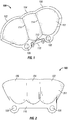
- Figure 1 illustrates a perspective bottom view of a directed beam reflector 100 in accordance with example embodiments of the present disclosure.
- Figure 2 illustrates a top view, or backside view, of the reflector 100 of Figure 1 , in accordance with example embodiments of the present disclosure.
- Figure 1 shows an inner surface 101 of the reflector 100
- Figure 2 shows an outer surface 201 of the reflector 100.
- Figure 3 illustrates a side view of the reflector 100 of Figures 1 and 2 , in accordance with example embodiments of the present disclosure.
- the mounting element 110 includes a coupling element such as an aperture 108 for coupling the reflector to a mounting surface.
- the mounting surface to which the reflector is to be mounted is a circuit board, a spacer, a fixture housing, or the like.
- the coupling element 108 is an aperture which traverses the mounting flange 110 configured to receive a screw threaded therethrough, in which the screw secures the mounting flange 110 to a mounting surface disposed adjacent to the mounting screw.
- the coupling element 108 is a snap, clip, pin, slot, or the like, and the mounting surface includes a corresponding coupling feature.
- the reflector includes one or more alignment elements such as alignment pins 112 for easily aligning the reflector with the mounting surface.
- the alignment feature is a depression, protrusion, slot, or another appropriate alignment or guide feature.
- the first reflector segment 102 includes a portion of a first curved three-dimensional shape
- the second reflector segment 104 includes a portion of a second curved three-dimensional shape
- the third reflector segment 106 includes a portion of a third curved three-dimensional shape.
- Reflector segments 102, 104 and 106 are connected at joints 114 as shown in the example in Figure 1 .
- each of the first, second, and third reflector segments 102, 104, 106 are concave ( Figure 1 ) in the same direction, forming the inner surface 101, and convex ( Figure 2 ) in the same direction, forming the outer surface 201.
- all or a subset of the first, second, and third curved three-dimensional shapes are paraboloids.
- the first reflector segment 102 is on a side of the reflector 100.
- an outer side 301 of the first reflector also forms an outer side 301 of the reflector 100.
- the outer side 301 includes a flank portion 303 which extends beyond the defined portion of the first paraboloid and includes an outer edge 302 which traverses a plane defined by the mounting surface.
- the configuration of the reflector 100 with respect to the mounting surface is described in further detail with reference to Figure 5 .
- the flank portion 303 deviates from, or does not follow, the contour of the paraboloid.
- the reflector 100 is fabricated from a plastic material having appropriate thermal characteristics such that the reflector is able to withstand a high temperature environment, such as that associated with LED lighting.
- the reflector 100 is primary fabricated from a polycarbonate material.
- the inner surface 101 of the reflector 100 is a reflective surface.
- the inner surface 101 is coated with a reflective material such as chrome, aluminum, silver, or the like.
- the process of applying such a coating is a high temperature process. Therefore the reflector 100 would be fabricated from a material of sufficient heat resistance to withstand not only an LED environment, but also the heating involved in applying a reflective coating.
- the reflector 100 includes more or less than three reflector segments.
- Figure 4 illustrates a reflector 400 having a fourth reflector segment 402 in accordance with an example embodiment of the present disclosure.
- the reflector 100 includes only two of the first, second, and third reflector segments 102, 104, 106.
- Figure 5 illustrates a side view of a reflector assembly 500 featuring the reflector 100 of Figures 1, 2 , and 3 , in accordance with an example embodiment of the present disclosure.
- Figure 5 further illustrates the first reflector segment 102 reflecting light from a first LED 506 into a first beam of light 520, in accordance with an example embodiment of the present disclosure.
- the reflector assembly 500 includes the reflector 100, a circuit board 502, and a spacer 504.
- the circuit board 502 includes a coupling element 508 such as an aperture or screw-hole.
- the reflector 100 is mounted onto the circuit board 502 such that the aperture 108 in the mounting element 110 of the reflector and the aperture 508 in the circuit board 502 are aligned and a screw can be threaded therethrough, securing the reflector 100 to the circuit board 502.
- the reflector 100 is mounted onto the circuit board 502 in an orientation in which the inner surface 101 of the reflector 100 faces the circuit board 502 and the outer surface 201 of the reflector 100 faces away from circuit board 502.
- the reflector 100 is mounted onto the circuit board 502 via a different coupling mechanism, such as a clip, snap, groove, and the like.
- the circuit board 502 is mounted on a spacer 504 such that the circuit board 502 is disposed between the reflector 100 and the spacer 504.
- the spacer 504 includes one or more apertures or screw-holes which align with the apertures or screw-holes in the circuit board 502 and the reflector 100.
- a screw is threaded through the reflector 100, the circuit board 502, and the spacer 504, thereby securing the three elements to each other.
- the spacer 504 is also secured to an optical housing on a lighting fixture when installed.
- the alignment pins 112 of the reflector 100 provide accurate alignment and relative positioning between the reflector 100, the circuit board 502, and/or the spacer 504.
- the spacer 504 is secured to the optical housing with one or more screws or another appropriate coupling device or element.
- the spacer 504 provides an angled surface on which the circuit board 502 is mounted, thereby providing an angle between the reflector 100 and the optical housing to which the spacer 504 is mounted.
- the spacer 504 further functions as a heat sink, dissipating a portion of the heat generated by the LEDs 506.
- the LED 506 can be positioned offset from the geometric focus 512 to achieve another desired lighting effect.
- the LED 506 is mounted as close to an edge 518 of the circuit board 502 as practicable, as excess surface area of the circuit board 502 may deflect more light emitted from the LED 506, reducing the overall brightness of the first beam of light 520.
- the outer side 301 of the reflector 100 includes a flank portion 303 and an outer edge 302 which traverses and extends beyond a plane 510 defined by the circuit board 502.
- the extra reflective surface provided by the flank portion 303 provides a stray light baffling function, which reduces the amount to light lost in the fixture and focusses more light into the first beam of light 520.
- Figure 6 illustrates a top view of the reflector assembly 500 of Figure 5 , in accordance with an example embodiment of the present disclosure.
- the circuit board 502 includes a first LED 506, a second LED 612, and a third LED 614 mounted thereon.
- the reflector 100 includes the first reflector segment 102, the second reflector segment 104, and the third reflector segment 106.
- the first reflector segment 102 reflects light emitted by the first LED 506 into a first beam of light 616
- the second reflector segment 104 reflects light emitted by the second LED 612 into a second beam of light 618
- the third reflector segment 106 reflects light emitted by the third LED 612 into a third beam of light 620.
- the reflector 100 includes more or less than three reflector segments, and the reflector assembly 500 includes more or less than three LEDs, thereby producing more or less than three light beams which converge to form the aggregate light beam.
- the reflector segments can be arranged differently to produce a different aggregate light beam. For example, in an embodiment, more reflector segments are arranged side by side to produce a wider aggregate light beam. Alternatively, in an example embodiment, reflector segments are arranged out of line with each other or stacked to produce an aggregate light of more height.
- Figure 7 illustrates an internal view of a light fixture 700 using the reflector 100, in accordance with example embodiments of the present disclosure. Specifically, Figure 7 illustrates the underside of an optical housing 702 of a runway light fixture 700.
- the optical housing 702 houses certain optical and electrical components which support the function of the light fixture 700.
- the light fixture 700 includes a first reflector assembly 500a and a second reflector assembly 500b.
- the first and second reflector assemblies 500a, 500b include first and second reflectors 100a, 100b, and first and second circuit boards 502a, 502b.
- the light fixture 700 further includes a first prism housing 704a and a second prism housing 704b, which house first and second prism 706a, 706b, respectively.
- first and second prisms 706a, 706b and the first and second prism housings 704a, 704b are positioned at a 180° rotation from each other so that light is emitted in opposite directions.
- the first and second reflector assemblies 500a, 500b are mounted onto the optical housing 702 substantially adjacent to and facing the first and second prism housings 704a, 704b, respectively as shown in Figure 7 .
- the prism housings 704a, 704b include a window which exposes the prisms 706a, 706b to the reflectors 100a, 100b.
- the prisms 706a, 706b are substantially perpendicular to the axis of symmetry 516 ( Figure 5 ) of the reflector segments, such that the aggregate light beams 622 ( Figure 6 ) reflected by the reflectors 100a, 100b enter the prisms 706a, 706b.
- the light beams 622 are directed by the prisms 706a, 706b and exit the fixture 700 on the top side (not shown) in a direction substantially parallel to the ground when the fixture 700 is installed on a runway, thus providing flat and focused light for runway lighting.
- the fixture 700 includes more or less than two reflector assemblies 500, and the reflector assemblies are arranged differently.
- the light fixture 700 is an elevated runway light or another type of airfield lighting fixture.
Landscapes
- Engineering & Computer Science (AREA)
- General Engineering & Computer Science (AREA)
- Non-Portable Lighting Devices Or Systems Thereof (AREA)
- Physics & Mathematics (AREA)
- Microelectronics & Electronic Packaging (AREA)
- Optics & Photonics (AREA)
Claims (11)
- Ensemble réflecteur à faisceau dirigé, comprenant :une carte de circuit (502) comprenant une première diode électroluminescente, LED, (506) et une deuxième LED (612), la carte de circuit (502) définissant un plan, et la carte de circuit (502) comprenant une ou plusieurs ouvertures de couplage (508) pour coupler un réflecteur (100) ; etle réflecteur (100) comprenant :un premier segment de réflecteur (102) ayant un premier axe optique (516) et un deuxième segment de réflecteur (104) ayant un deuxième axe optique (516), et le premier segment de réflecteur (102) étant sensiblement aligné avec la première LED (506) et le deuxième segment de réflecteur (104) étant sensiblement aligné avec la deuxième LED (612), etun rebord de montage (110) intégré dans le réflecteur (100) et agencé pour monter le réflecteur (100) sur la carte de circuit (502) :dans lequel le réflecteur (100) est monté sur la carte de circuit (502) de telle sorte que :une surface intérieure (101) du premier segment de réflecteur (102) s'étend à partir de la carte de circuit (502) au niveau du rebord de montage (110) au-dessus de la première LED (506) et en direction d'un bord (518) de la carte de circuit (502) qui est adjacent à la première LED (506),une surface intérieure (101) du deuxième segment de réflecteur (104) s'étend à partir de la carte de circuit (502) au niveau du rebord de montage (110) au-dessus de la deuxième LED (612) et en direction d'un bord (518) de la carte de circuit (502) qui est adjacent à la deuxième LED (612), etle plan de la carte de circuit (502) fait un angle aigu avec le premier axe optique (516) et le deuxième axe optique (516) pour améliorer le rendement optique du premier segment de réflecteur (102) et du deuxième segment de réflecteur (104), etdans lequel le premier segment de réflecteur (102) focalise sensiblement la lumière provenant de la première LED (506) en un premier faisceau de lumière (616) qui est dirigé selon l'angle par rapport au plan défini par la carte de circuit (502) ; le deuxième segment de réflecteur (104) focalise sensiblement la lumière provenant de la deuxième LED (612) en un deuxième faisceau de lumière (618) qui est dirigé selon l'angle par rapport au plan défini par la carte de circuit (502) ; etle premier faisceau de lumière (116) et le deuxième faisceau de lumière (618) forment un faisceau de lumière agrégé (622).
- Ensemble réflecteur à faisceau dirigé selon la revendication 1, dans lequel le réflecteur (100) comprend un bord droit (302) et un bord gauche (302), dans lequel les bords droit et gauche (302) s'étendent au-delà du plan défini par la carte de circuit (502).
- Ensemble réflecteur à faisceau dirigé selon la revendication 1, dans lequel le rebord de montage (110) est monté sur la carte de circuit (502) et la carte de circuit (502) est couplée à une entretoise (504) par l'intermédiaire d'une ou plusieurs vis.
- Ensemble réflecteur à faisceau dirigé selon la revendication 1, dans lequel :le premier segment de réflecteur (102) comprend une première surface réfléchissante courbe (101) et une portion d'une première forme tridimensionnelle courbe ; etle deuxième segment de réflecteur (104) comprend une deuxième surface réfléchissante courbe (101) jointe à la première portion de réflecteur, et comprend une portion d'une deuxième forme tridimensionnelle courbe.
- Ensemble réflecteur à faisceau dirigé selon la revendication 4, dans lequel le réflecteur (100) comprend en outre un troisième segment de réflecteur (106) joint au deuxième segment de réflecteur (104) opposé au premier segment de réflecteur (102), le troisième segment de réflecteur (106) comprenant une troisième surface réfléchissante courbe (101) et une portion d'une troisième forme tridimensionnelle courbe.
- Ensemble réflecteur à faisceau dirigé selon la revendication 4, dans lequel la première forme tridimensionnelle courbe et la deuxième forme tridimensionnelle courbe comprennent des premier et deuxième paraboloïdes, respectivement.
- Ensemble réflecteur à faisceau dirigé selon la revendication 6, dans lequel la première LED (506) est disposée approximativement au foyer géométrique (512) du premier paraboloïde.
- Réflecteur à faisceau dirigé selon la revendication 1, dans lequel la convergence horizontale du faisceau de lumière agrégé (622) est d'environ 8 à 12 degrés et la convergence verticale du faisceau lumineux agrégé (622) est d'environ 3 à 5 degrés.
- Ensemble réflecteur à faisceau dirigé selon la revendication 3, dans lequel l'entretoise (504) comprend une ou plusieurs ouvertures qui sont alignées avec lesdites une ou plusieurs ouvertures de couplage de la carte de circuit (502) lorsque la carte de circuit (502) et le réflecteur (100) sont montés sur l'entretoise (504).
- Ensemble réflecteur à faisceau dirigé selon la revendication 1, dans lequel l'ensemble réflecteur à faisceau dirigé est placé adjacent à un logement de prisme (704) dans un boîtier optique (702) de sorte que le faisceau de lumière agrégé (622) provenant du réflecteur (100) rentre dans le logement de prisme (704) par l'intermédiaire d'une fenêtre de logement de prisme et est dirigé par un prisme (706) dans le logement de prisme (704) pour sortir du boitier optique (702).
- Ensemble réflecteur à faisceau dirigé selon la revendication 1, dans lequel le faisceau de lumière agrégé (622) est plus large que haut, la largeur étant mesurée dans une direction horizontale traversant le réflecteur (100).
Applications Claiming Priority (2)
| Application Number | Priority Date | Filing Date | Title |
|---|---|---|---|
| US13/933,818 US9696008B2 (en) | 2013-07-02 | 2013-07-02 | Reflector for directed beam LED illumination |
| PCT/US2014/045016 WO2015002928A1 (fr) | 2013-07-02 | 2014-07-01 | Réflecteur pour éclairage à diodes électroluminescentes à faisceaux dirigés |
Publications (3)
| Publication Number | Publication Date |
|---|---|
| EP3027963A1 EP3027963A1 (fr) | 2016-06-08 |
| EP3027963A4 EP3027963A4 (fr) | 2016-11-23 |
| EP3027963B1 true EP3027963B1 (fr) | 2018-04-18 |
Family
ID=52132692
Family Applications (1)
| Application Number | Title | Priority Date | Filing Date |
|---|---|---|---|
| EP14820677.4A Active EP3027963B1 (fr) | 2013-07-02 | 2014-07-01 | Réflecteur pour éclairage à diodes électroluminescentes à faisceaux dirigés |
Country Status (6)
| Country | Link |
|---|---|
| US (1) | US9696008B2 (fr) |
| EP (1) | EP3027963B1 (fr) |
| KR (1) | KR102304154B1 (fr) |
| CN (1) | CN105378376B (fr) |
| ES (1) | ES2675008T3 (fr) |
| WO (1) | WO2015002928A1 (fr) |
Families Citing this family (12)
| Publication number | Priority date | Publication date | Assignee | Title |
|---|---|---|---|---|
| US10253956B2 (en) | 2015-08-26 | 2019-04-09 | Abl Ip Holding Llc | LED luminaire with mounting structure for LED circuit board |
| TWM547065U (zh) * | 2017-04-14 | 2017-08-11 | 軒帆光電科技股份有限公司 | 用於照明裝置之光源模組 |
| EP3656682B1 (fr) | 2017-05-09 | 2021-08-25 | Eaton Intelligent Power Limited | Éclairage de terrain d'aviation |
| EP3401224B1 (fr) | 2017-05-09 | 2020-07-29 | Eaton Intelligent Power Limited | Éclairage de terrain d'aviation |
| CA3072578A1 (fr) * | 2017-08-15 | 2019-02-21 | Eaton Intelligent Power Limited | Feu de balisage d'aerodrome |
| CN108036203A (zh) * | 2017-12-13 | 2018-05-15 | 上海航安机场设备有限公司 | 用于机场跑道灯的led光学组件 |
| US10251279B1 (en) | 2018-01-04 | 2019-04-02 | Abl Ip Holding Llc | Printed circuit board mounting with tabs |
| EP3738889B1 (fr) * | 2019-05-17 | 2024-08-07 | Goodrich Lighting Systems GmbH | Dispositif d'éclairage, aéronef comprenant un tel dispositif d'éclairage et procédé de fabrication d'un dispositif d'éclairage |
| CN113432064A (zh) * | 2021-06-30 | 2021-09-24 | 航达康机电技术(武汉)有限公司 | 一种具有更多安装空间的航灯结构 |
| US20250145081A1 (en) * | 2022-07-12 | 2025-05-08 | Muth Mirror Systems, Llc | Reflecting optic assembly |
| KR102588715B1 (ko) | 2022-10-14 | 2023-10-13 | 박웅기 | 배관 피팅의 흄 가스 누설 방지장치 |
| US12398875B2 (en) * | 2022-12-17 | 2025-08-26 | Eaton Intelligent Power Limited | Lightweight and compact elevated approach light |
Family Cites Families (31)
| Publication number | Priority date | Publication date | Assignee | Title |
|---|---|---|---|---|
| US3390262A (en) * | 1965-05-24 | 1968-06-25 | Sylvania Electric Prod | Multizone high power light reflector |
| US4242725A (en) * | 1977-12-01 | 1980-12-30 | Sun Chemical Corporation | Light reflector structure |
| US4261030A (en) * | 1979-03-15 | 1981-04-07 | Esquire, Inc. | Wrap-around parabolic light fixture and method for manufacture |
| US4336576A (en) * | 1980-04-07 | 1982-06-22 | Crabtree Daniel B | Lighting apparatus |
| DE60223050T2 (de) * | 2001-08-31 | 2008-07-17 | Gentex Corp., Zeeland | Fahrzeuglampenanordnung mit kühlkörper |
| JP4027688B2 (ja) * | 2002-03-15 | 2007-12-26 | 株式会社小糸製作所 | 車両用灯具 |
| US6851835B2 (en) | 2002-12-17 | 2005-02-08 | Whelen Engineering Company, Inc. | Large area shallow-depth full-fill LED light assembly |
| EP1671063B1 (fr) | 2003-10-10 | 2013-03-06 | Federal Signal Corporation | Ensemble lumineux |
| US8197110B2 (en) * | 2003-10-10 | 2012-06-12 | Federal Signal Corporation | Light assembly incorporating reflective features |
| US7070301B2 (en) | 2003-11-04 | 2006-07-04 | 3M Innovative Properties Company | Side reflector for illumination using light emitting diode |
| JP2005166590A (ja) * | 2003-12-05 | 2005-06-23 | Koito Mfg Co Ltd | 車両用前照灯 |
| US7040782B2 (en) | 2004-02-19 | 2006-05-09 | Gelcore, Llc | Off-axis parabolic reflector |
| ITBO20050606A1 (it) | 2005-10-11 | 2007-04-12 | Ocem Spa | Segnalatore luminoso a semilivello |
| US7824067B2 (en) | 2007-03-21 | 2010-11-02 | Thomas & Betts International, Inc. | Emergency light fixture having an efficient reflector assembly |
| JP5212785B2 (ja) * | 2008-02-22 | 2013-06-19 | スタンレー電気株式会社 | 車両用前照灯 |
| US20100226139A1 (en) * | 2008-12-05 | 2010-09-09 | Permlight Products, Inc. | Led-based light engine |
| JP2011076858A (ja) * | 2009-09-30 | 2011-04-14 | Koito Mfg Co Ltd | 車輌用灯具 |
| CN102713421A (zh) * | 2009-11-18 | 2012-10-03 | 拉姆伯斯国际公司 | Led的内部收集反射器光学器件 |
| CN102087004B (zh) * | 2009-12-03 | 2014-06-11 | 马士科技有限公司 | 发光二极管灯和其中的反光杯 |
| DE102010018178A1 (de) | 2010-04-22 | 2011-10-27 | Hella Kgaa Hueck & Co. | Beleuchtungsvorrichtung für eine Flughafenrollbahn |
| JP5338746B2 (ja) * | 2010-05-12 | 2013-11-13 | 市光工業株式会社 | 車両用灯具 |
| EP2428725B1 (fr) * | 2010-09-10 | 2019-11-20 | Koito Manufacturing Co., Ltd. | Phare de véhicule |
| US8672515B2 (en) * | 2010-11-15 | 2014-03-18 | Power Products, Llc | Marine spotlight |
| US8485684B2 (en) | 2011-05-13 | 2013-07-16 | GE Lighting Solutions, LLC | LED roadway luminaire |
| KR101234323B1 (ko) * | 2011-05-25 | 2013-02-18 | 현대모비스 주식회사 | 차량용 헤드램프 장치 |
| US8616724B2 (en) | 2011-06-23 | 2013-12-31 | Cree, Inc. | Solid state directional lamp including retroreflective, multi-element directional lamp optic |
| JP5716576B2 (ja) * | 2011-06-30 | 2015-05-13 | スタンレー電気株式会社 | 車両用灯具ユニット |
| JP2013093157A (ja) * | 2011-10-25 | 2013-05-16 | Ichikoh Ind Ltd | 車両用前照灯 |
| CN202432395U (zh) | 2012-01-13 | 2012-09-12 | 佛山市国星光电股份有限公司 | 基于led三维封装的汽车前大灯 |
| JP5945857B2 (ja) * | 2012-01-24 | 2016-07-05 | スタンレー電気株式会社 | 車両用前照灯及び導光レンズ |
| JP6195747B2 (ja) * | 2012-10-22 | 2017-09-13 | 株式会社小糸製作所 | 灯具ユニット及び車両用灯具 |
-
2013
- 2013-07-02 US US13/933,818 patent/US9696008B2/en active Active
-
2014
- 2014-07-01 ES ES14820677.4T patent/ES2675008T3/es active Active
- 2014-07-01 CN CN201480038339.9A patent/CN105378376B/zh active Active
- 2014-07-01 EP EP14820677.4A patent/EP3027963B1/fr active Active
- 2014-07-01 KR KR1020167002740A patent/KR102304154B1/ko active Active
- 2014-07-01 WO PCT/US2014/045016 patent/WO2015002928A1/fr not_active Ceased
Non-Patent Citations (1)
| Title |
|---|
| None * |
Also Published As
| Publication number | Publication date |
|---|---|
| EP3027963A4 (fr) | 2016-11-23 |
| WO2015002928A1 (fr) | 2015-01-08 |
| CN105378376A (zh) | 2016-03-02 |
| KR102304154B1 (ko) | 2021-09-27 |
| CN105378376B (zh) | 2019-01-15 |
| EP3027963A1 (fr) | 2016-06-08 |
| US9696008B2 (en) | 2017-07-04 |
| KR20160027142A (ko) | 2016-03-09 |
| ES2675008T3 (es) | 2018-07-05 |
| US20150009678A1 (en) | 2015-01-08 |
Similar Documents
| Publication | Publication Date | Title |
|---|---|---|
| EP3027963B1 (fr) | Réflecteur pour éclairage à diodes électroluminescentes à faisceaux dirigés | |
| KR101601261B1 (ko) | Led 설비용 오리엔터블 렌즈 | |
| RU2502919C2 (ru) | Ориентируемая линза для светодиодного светильника | |
| CN102252264A (zh) | 发光装置 | |
| US7300185B1 (en) | Quadrilateral symmetrical light source | |
| US20140218933A1 (en) | Detachable lamp | |
| CN101963327B (zh) | 反射罩及照明装置 | |
| CN103791255B (zh) | 发光二极管灯泡 | |
| JP6241601B2 (ja) | 照明装置 | |
| CN207907016U (zh) | 照明灯具的配光组件、光源模组及照明灯具 | |
| US20170130935A1 (en) | Optical lens and a spotlight including the same | |
| CN206890162U (zh) | 一种光源模组及灯具 | |
| CN112867892A (zh) | 照明系统 | |
| KR20150032504A (ko) | Led 가로등 | |
| CN204240106U (zh) | 照明装置 | |
| US20170002999A1 (en) | Discontinuous annular reflector for lamp | |
| CN204785874U (zh) | 一种led灯具 | |
| TWI524036B (zh) | 燈具 | |
| CN111365678B (zh) | 激光照明模组及调节方法 | |
| US10808892B2 (en) | Light source for a luminaire | |
| US10119680B2 (en) | Retrofit light emitting diode fixture for a back box | |
| CN115727285A (zh) | 光学组件、光学系统、光学系统装配方法以及灯具 | |
| CN101963325B (zh) | 反射罩及照明装置 | |
| KR20150078209A (ko) | 조명기기 | |
| HK40024549A (en) | Light source for a luminaire |
Legal Events
| Date | Code | Title | Description |
|---|---|---|---|
| PUAI | Public reference made under article 153(3) epc to a published international application that has entered the european phase |
Free format text: ORIGINAL CODE: 0009012 |
|
| 17P | Request for examination filed |
Effective date: 20151229 |
|
| AK | Designated contracting states |
Kind code of ref document: A1 Designated state(s): AL AT BE BG CH CY CZ DE DK EE ES FI FR GB GR HR HU IE IS IT LI LT LU LV MC MK MT NL NO PL PT RO RS SE SI SK SM TR |
|
| AX | Request for extension of the european patent |
Extension state: BA ME |
|
| DAX | Request for extension of the european patent (deleted) | ||
| A4 | Supplementary search report drawn up and despatched |
Effective date: 20161020 |
|
| RIC1 | Information provided on ipc code assigned before grant |
Ipc: F21V 7/04 20060101ALI20161014BHEP Ipc: F21V 7/22 20060101ALN20161014BHEP Ipc: F21V 19/00 20060101ALN20161014BHEP Ipc: F21Y 101/00 20160101ALI20161014BHEP Ipc: F21V 7/06 20060101AFI20161014BHEP Ipc: F21Y 105/10 20160101ALN20161014BHEP Ipc: F21W 111/06 20060101ALI20161014BHEP Ipc: F21V 17/12 20060101ALN20161014BHEP Ipc: F21V 7/09 20060101ALI20161014BHEP Ipc: F21Y 115/10 20160101ALN20161014BHEP |
|
| RIC1 | Information provided on ipc code assigned before grant |
Ipc: F21V 7/09 20060101ALI20171002BHEP Ipc: F21V 17/12 20060101ALN20171002BHEP Ipc: F21Y 105/10 20160101ALN20171002BHEP Ipc: F21W 111/06 20060101ALI20171002BHEP Ipc: F21Y 101/00 20160101ALI20171002BHEP Ipc: F21V 7/04 20060101ALI20171002BHEP Ipc: F21V 7/06 20060101AFI20171002BHEP Ipc: F21V 7/22 20060101ALN20171002BHEP Ipc: F21V 19/00 20060101ALN20171002BHEP Ipc: F21Y 115/10 20160101ALN20171002BHEP |
|
| GRAP | Despatch of communication of intention to grant a patent |
Free format text: ORIGINAL CODE: EPIDOSNIGR1 |
|
| INTG | Intention to grant announced |
Effective date: 20171113 |
|
| GRAS | Grant fee paid |
Free format text: ORIGINAL CODE: EPIDOSNIGR3 |
|
| GRAA | (expected) grant |
Free format text: ORIGINAL CODE: 0009210 |
|
| AK | Designated contracting states |
Kind code of ref document: B1 Designated state(s): AL AT BE BG CH CY CZ DE DK EE ES FI FR GB GR HR HU IE IS IT LI LT LU LV MC MK MT NL NO PL PT RO RS SE SI SK SM TR |
|
| REG | Reference to a national code |
Ref country code: GB Ref legal event code: FG4D |
|
| REG | Reference to a national code |
Ref country code: CH Ref legal event code: EP |
|
| REG | Reference to a national code |
Ref country code: AT Ref legal event code: REF Ref document number: 990900 Country of ref document: AT Kind code of ref document: T Effective date: 20180515 |
|
| REG | Reference to a national code |
Ref country code: IE Ref legal event code: FG4D |
|
| REG | Reference to a national code |
Ref country code: DE Ref legal event code: R096 Ref document number: 602014024217 Country of ref document: DE |
|
| REG | Reference to a national code |
Ref country code: FR Ref legal event code: PLFP Year of fee payment: 5 |
|
| REG | Reference to a national code |
Ref country code: ES Ref legal event code: FG2A Ref document number: 2675008 Country of ref document: ES Kind code of ref document: T3 Effective date: 20180705 |
|
| REG | Reference to a national code |
Ref country code: NL Ref legal event code: MP Effective date: 20180418 |
|
| REG | Reference to a national code |
Ref country code: LT Ref legal event code: MG4D |
|
| PG25 | Lapsed in a contracting state [announced via postgrant information from national office to epo] |
Ref country code: NL Free format text: LAPSE BECAUSE OF FAILURE TO SUBMIT A TRANSLATION OF THE DESCRIPTION OR TO PAY THE FEE WITHIN THE PRESCRIBED TIME-LIMIT Effective date: 20180418 |
|
| PG25 | Lapsed in a contracting state [announced via postgrant information from national office to epo] |
Ref country code: AL Free format text: LAPSE BECAUSE OF FAILURE TO SUBMIT A TRANSLATION OF THE DESCRIPTION OR TO PAY THE FEE WITHIN THE PRESCRIBED TIME-LIMIT Effective date: 20180418 Ref country code: BG Free format text: LAPSE BECAUSE OF FAILURE TO SUBMIT A TRANSLATION OF THE DESCRIPTION OR TO PAY THE FEE WITHIN THE PRESCRIBED TIME-LIMIT Effective date: 20180718 Ref country code: FI Free format text: LAPSE BECAUSE OF FAILURE TO SUBMIT A TRANSLATION OF THE DESCRIPTION OR TO PAY THE FEE WITHIN THE PRESCRIBED TIME-LIMIT Effective date: 20180418 Ref country code: PL Free format text: LAPSE BECAUSE OF FAILURE TO SUBMIT A TRANSLATION OF THE DESCRIPTION OR TO PAY THE FEE WITHIN THE PRESCRIBED TIME-LIMIT Effective date: 20180418 Ref country code: LT Free format text: LAPSE BECAUSE OF FAILURE TO SUBMIT A TRANSLATION OF THE DESCRIPTION OR TO PAY THE FEE WITHIN THE PRESCRIBED TIME-LIMIT Effective date: 20180418 Ref country code: SE Free format text: LAPSE BECAUSE OF FAILURE TO SUBMIT A TRANSLATION OF THE DESCRIPTION OR TO PAY THE FEE WITHIN THE PRESCRIBED TIME-LIMIT Effective date: 20180418 Ref country code: NO Free format text: LAPSE BECAUSE OF FAILURE TO SUBMIT A TRANSLATION OF THE DESCRIPTION OR TO PAY THE FEE WITHIN THE PRESCRIBED TIME-LIMIT Effective date: 20180718 |
|
| PG25 | Lapsed in a contracting state [announced via postgrant information from national office to epo] |
Ref country code: HR Free format text: LAPSE BECAUSE OF FAILURE TO SUBMIT A TRANSLATION OF THE DESCRIPTION OR TO PAY THE FEE WITHIN THE PRESCRIBED TIME-LIMIT Effective date: 20180418 Ref country code: GR Free format text: LAPSE BECAUSE OF FAILURE TO SUBMIT A TRANSLATION OF THE DESCRIPTION OR TO PAY THE FEE WITHIN THE PRESCRIBED TIME-LIMIT Effective date: 20180719 Ref country code: LV Free format text: LAPSE BECAUSE OF FAILURE TO SUBMIT A TRANSLATION OF THE DESCRIPTION OR TO PAY THE FEE WITHIN THE PRESCRIBED TIME-LIMIT Effective date: 20180418 Ref country code: RS Free format text: LAPSE BECAUSE OF FAILURE TO SUBMIT A TRANSLATION OF THE DESCRIPTION OR TO PAY THE FEE WITHIN THE PRESCRIBED TIME-LIMIT Effective date: 20180418 |
|
| REG | Reference to a national code |
Ref country code: AT Ref legal event code: MK05 Ref document number: 990900 Country of ref document: AT Kind code of ref document: T Effective date: 20180418 |
|
| PG25 | Lapsed in a contracting state [announced via postgrant information from national office to epo] |
Ref country code: PT Free format text: LAPSE BECAUSE OF FAILURE TO SUBMIT A TRANSLATION OF THE DESCRIPTION OR TO PAY THE FEE WITHIN THE PRESCRIBED TIME-LIMIT Effective date: 20180820 |
|
| REG | Reference to a national code |
Ref country code: DE Ref legal event code: R097 Ref document number: 602014024217 Country of ref document: DE |
|
| PG25 | Lapsed in a contracting state [announced via postgrant information from national office to epo] |
Ref country code: SK Free format text: LAPSE BECAUSE OF FAILURE TO SUBMIT A TRANSLATION OF THE DESCRIPTION OR TO PAY THE FEE WITHIN THE PRESCRIBED TIME-LIMIT Effective date: 20180418 Ref country code: EE Free format text: LAPSE BECAUSE OF FAILURE TO SUBMIT A TRANSLATION OF THE DESCRIPTION OR TO PAY THE FEE WITHIN THE PRESCRIBED TIME-LIMIT Effective date: 20180418 Ref country code: CZ Free format text: LAPSE BECAUSE OF FAILURE TO SUBMIT A TRANSLATION OF THE DESCRIPTION OR TO PAY THE FEE WITHIN THE PRESCRIBED TIME-LIMIT Effective date: 20180418 Ref country code: RO Free format text: LAPSE BECAUSE OF FAILURE TO SUBMIT A TRANSLATION OF THE DESCRIPTION OR TO PAY THE FEE WITHIN THE PRESCRIBED TIME-LIMIT Effective date: 20180418 Ref country code: AT Free format text: LAPSE BECAUSE OF FAILURE TO SUBMIT A TRANSLATION OF THE DESCRIPTION OR TO PAY THE FEE WITHIN THE PRESCRIBED TIME-LIMIT Effective date: 20180418 Ref country code: DK Free format text: LAPSE BECAUSE OF FAILURE TO SUBMIT A TRANSLATION OF THE DESCRIPTION OR TO PAY THE FEE WITHIN THE PRESCRIBED TIME-LIMIT Effective date: 20180418 |
|
| PLBE | No opposition filed within time limit |
Free format text: ORIGINAL CODE: 0009261 |
|
| STAA | Information on the status of an ep patent application or granted ep patent |
Free format text: STATUS: NO OPPOSITION FILED WITHIN TIME LIMIT |
|
| PG25 | Lapsed in a contracting state [announced via postgrant information from national office to epo] |
Ref country code: SM Free format text: LAPSE BECAUSE OF FAILURE TO SUBMIT A TRANSLATION OF THE DESCRIPTION OR TO PAY THE FEE WITHIN THE PRESCRIBED TIME-LIMIT Effective date: 20180418 |
|
| REG | Reference to a national code |
Ref country code: CH Ref legal event code: PL |
|
| 26N | No opposition filed |
Effective date: 20190121 |
|
| PG25 | Lapsed in a contracting state [announced via postgrant information from national office to epo] |
Ref country code: MC Free format text: LAPSE BECAUSE OF FAILURE TO SUBMIT A TRANSLATION OF THE DESCRIPTION OR TO PAY THE FEE WITHIN THE PRESCRIBED TIME-LIMIT Effective date: 20180418 Ref country code: LU Free format text: LAPSE BECAUSE OF NON-PAYMENT OF DUE FEES Effective date: 20180701 |
|
| REG | Reference to a national code |
Ref country code: IE Ref legal event code: MM4A |
|
| PG25 | Lapsed in a contracting state [announced via postgrant information from national office to epo] |
Ref country code: CH Free format text: LAPSE BECAUSE OF NON-PAYMENT OF DUE FEES Effective date: 20180731 Ref country code: IE Free format text: LAPSE BECAUSE OF NON-PAYMENT OF DUE FEES Effective date: 20180701 Ref country code: LI Free format text: LAPSE BECAUSE OF NON-PAYMENT OF DUE FEES Effective date: 20180731 |
|
| PG25 | Lapsed in a contracting state [announced via postgrant information from national office to epo] |
Ref country code: SI Free format text: LAPSE BECAUSE OF FAILURE TO SUBMIT A TRANSLATION OF THE DESCRIPTION OR TO PAY THE FEE WITHIN THE PRESCRIBED TIME-LIMIT Effective date: 20180418 |
|
| PG25 | Lapsed in a contracting state [announced via postgrant information from national office to epo] |
Ref country code: MT Free format text: LAPSE BECAUSE OF NON-PAYMENT OF DUE FEES Effective date: 20180701 |
|
| PG25 | Lapsed in a contracting state [announced via postgrant information from national office to epo] |
Ref country code: TR Free format text: LAPSE BECAUSE OF FAILURE TO SUBMIT A TRANSLATION OF THE DESCRIPTION OR TO PAY THE FEE WITHIN THE PRESCRIBED TIME-LIMIT Effective date: 20180418 |
|
| PG25 | Lapsed in a contracting state [announced via postgrant information from national office to epo] |
Ref country code: MK Free format text: LAPSE BECAUSE OF NON-PAYMENT OF DUE FEES Effective date: 20180418 Ref country code: HU Free format text: LAPSE BECAUSE OF FAILURE TO SUBMIT A TRANSLATION OF THE DESCRIPTION OR TO PAY THE FEE WITHIN THE PRESCRIBED TIME-LIMIT; INVALID AB INITIO Effective date: 20140701 Ref country code: CY Free format text: LAPSE BECAUSE OF FAILURE TO SUBMIT A TRANSLATION OF THE DESCRIPTION OR TO PAY THE FEE WITHIN THE PRESCRIBED TIME-LIMIT Effective date: 20180418 |
|
| PG25 | Lapsed in a contracting state [announced via postgrant information from national office to epo] |
Ref country code: IS Free format text: LAPSE BECAUSE OF FAILURE TO SUBMIT A TRANSLATION OF THE DESCRIPTION OR TO PAY THE FEE WITHIN THE PRESCRIBED TIME-LIMIT Effective date: 20180818 |
|
| P01 | Opt-out of the competence of the unified patent court (upc) registered |
Effective date: 20230521 |
|
| PGFP | Annual fee paid to national office [announced via postgrant information from national office to epo] |
Ref country code: GB Payment date: 20240620 Year of fee payment: 11 |
|
| PGFP | Annual fee paid to national office [announced via postgrant information from national office to epo] |
Ref country code: FR Payment date: 20240619 Year of fee payment: 11 |
|
| PGFP | Annual fee paid to national office [announced via postgrant information from national office to epo] |
Ref country code: BE Payment date: 20240619 Year of fee payment: 11 |
|
| PGFP | Annual fee paid to national office [announced via postgrant information from national office to epo] |
Ref country code: IT Payment date: 20240619 Year of fee payment: 11 |
|
| PGFP | Annual fee paid to national office [announced via postgrant information from national office to epo] |
Ref country code: DE Payment date: 20240619 Year of fee payment: 11 |
|
| PGFP | Annual fee paid to national office [announced via postgrant information from national office to epo] |
Ref country code: ES Payment date: 20240802 Year of fee payment: 11 |
|
| REG | Reference to a national code |
Ref country code: DE Ref legal event code: R119 Ref document number: 602014024217 Country of ref document: DE |
|
| GBPC | Gb: european patent ceased through non-payment of renewal fee |
Effective date: 20250701 |
|
| REG | Reference to a national code |
Ref country code: BE Ref legal event code: MM Effective date: 20250731 |
|
| PG25 | Lapsed in a contracting state [announced via postgrant information from national office to epo] |
Ref country code: GB Free format text: LAPSE BECAUSE OF NON-PAYMENT OF DUE FEES Effective date: 20250701 |
|
| PG25 | Lapsed in a contracting state [announced via postgrant information from national office to epo] |
Ref country code: DE Free format text: LAPSE BECAUSE OF NON-PAYMENT OF DUE FEES Effective date: 20260203 |
|
| PG25 | Lapsed in a contracting state [announced via postgrant information from national office to epo] |
Ref country code: BE Free format text: LAPSE BECAUSE OF NON-PAYMENT OF DUE FEES Effective date: 20250731 |
|
| PG25 | Lapsed in a contracting state [announced via postgrant information from national office to epo] |
Ref country code: FR Free format text: LAPSE BECAUSE OF NON-PAYMENT OF DUE FEES Effective date: 20250731 |