EP3028056B1 - Fehlererkennungsvorrichtung für ein strasssenlampenbeleuchtungssystem und verfahren zum betrieb davon - Google Patents
Fehlererkennungsvorrichtung für ein strasssenlampenbeleuchtungssystem und verfahren zum betrieb davon Download PDFInfo
- Publication number
- EP3028056B1 EP3028056B1 EP14744105.9A EP14744105A EP3028056B1 EP 3028056 B1 EP3028056 B1 EP 3028056B1 EP 14744105 A EP14744105 A EP 14744105A EP 3028056 B1 EP3028056 B1 EP 3028056B1
- Authority
- EP
- European Patent Office
- Prior art keywords
- control unit
- state
- detection control
- fault
- detection
- Prior art date
- Legal status (The legal status is an assumption and is not a legal conclusion. Google has not performed a legal analysis and makes no representation as to the accuracy of the status listed.)
- Active
Links
Images


Classifications
-
- H—ELECTRICITY
- H05—ELECTRIC TECHNIQUES NOT OTHERWISE PROVIDED FOR
- H05B—ELECTRIC HEATING; ELECTRIC LIGHT SOURCES NOT OTHERWISE PROVIDED FOR; CIRCUIT ARRANGEMENTS FOR ELECTRIC LIGHT SOURCES, IN GENERAL
- H05B47/00—Circuit arrangements for operating light sources in general, i.e. where the type of light source is not relevant
- H05B47/20—Responsive to malfunctions or to light source life; for protection
- H05B47/21—Responsive to malfunctions or to light source life; for protection of two or more light sources connected in parallel
- H05B47/22—Responsive to malfunctions or to light source life; for protection of two or more light sources connected in parallel with communication between the lamps and a central unit
-
- H—ELECTRICITY
- H05—ELECTRIC TECHNIQUES NOT OTHERWISE PROVIDED FOR
- H05B—ELECTRIC HEATING; ELECTRIC LIGHT SOURCES NOT OTHERWISE PROVIDED FOR; CIRCUIT ARRANGEMENTS FOR ELECTRIC LIGHT SOURCES, IN GENERAL
- H05B47/00—Circuit arrangements for operating light sources in general, i.e. where the type of light source is not relevant
- H05B47/10—Controlling the light source
- H05B47/105—Controlling the light source in response to determined parameters
- H05B47/11—Controlling the light source in response to determined parameters by determining the brightness or colour temperature of ambient light
-
- H—ELECTRICITY
- H05—ELECTRIC TECHNIQUES NOT OTHERWISE PROVIDED FOR
- H05B—ELECTRIC HEATING; ELECTRIC LIGHT SOURCES NOT OTHERWISE PROVIDED FOR; CIRCUIT ARRANGEMENTS FOR ELECTRIC LIGHT SOURCES, IN GENERAL
- H05B47/00—Circuit arrangements for operating light sources in general, i.e. where the type of light source is not relevant
- H05B47/10—Controlling the light source
- H05B47/175—Controlling the light source by remote control
- H05B47/185—Controlling the light source by remote control via power line carrier transmission
-
- Y—GENERAL TAGGING OF NEW TECHNOLOGICAL DEVELOPMENTS; GENERAL TAGGING OF CROSS-SECTIONAL TECHNOLOGIES SPANNING OVER SEVERAL SECTIONS OF THE IPC; TECHNICAL SUBJECTS COVERED BY FORMER USPC CROSS-REFERENCE ART COLLECTIONS [XRACs] AND DIGESTS
- Y02—TECHNOLOGIES OR APPLICATIONS FOR MITIGATION OR ADAPTATION AGAINST CLIMATE CHANGE
- Y02B—CLIMATE CHANGE MITIGATION TECHNOLOGIES RELATED TO BUILDINGS, e.g. HOUSING, HOUSE APPLIANCES OR RELATED END-USER APPLICATIONS
- Y02B20/00—Energy efficient lighting technologies, e.g. halogen lamps or gas discharge lamps
- Y02B20/40—Control techniques providing energy savings, e.g. smart controller or presence detection
-
- Y—GENERAL TAGGING OF NEW TECHNOLOGICAL DEVELOPMENTS; GENERAL TAGGING OF CROSS-SECTIONAL TECHNOLOGIES SPANNING OVER SEVERAL SECTIONS OF THE IPC; TECHNICAL SUBJECTS COVERED BY FORMER USPC CROSS-REFERENCE ART COLLECTIONS [XRACs] AND DIGESTS
- Y02—TECHNOLOGIES OR APPLICATIONS FOR MITIGATION OR ADAPTATION AGAINST CLIMATE CHANGE
- Y02B—CLIMATE CHANGE MITIGATION TECHNOLOGIES RELATED TO BUILDINGS, e.g. HOUSING, HOUSE APPLIANCES OR RELATED END-USER APPLICATIONS
- Y02B20/00—Energy efficient lighting technologies, e.g. halogen lamps or gas discharge lamps
- Y02B20/72—Energy efficient lighting technologies, e.g. halogen lamps or gas discharge lamps in street lighting
Definitions
- the present invention relates to a fault detection device for streetlamp lighting system and a method of operating the same
- the streetlamp lighting system is widely used in different streets, and provides an effective lighting effect at night for the road or a particular region. Due to the universality of the streetlamp lighting system, lots of electric connecting lines are needed, and most of the electric lines have many security problems as they are unattended, for instance, the power cable of the lighting system may be subject to steeling or destroying, which causes most of the lighting devices incapable of running normally and appropriate lighting cannot be obtained on the road at night.
- detection of cable fault is realized by calculating the impedance value of the cable line, wherein the power line carrier measure is used to complete the process, and high-value power impedance devices paralleled with each lighting device are used during the process.
- a fault position is determined by measuring a return-voltage and resonant frequency with a dedicated theft-proof measurement instrument and a capacitor, wherein a variable-frequency and constant-amplitude AC current source is used in the fault detection.
- EP 1 672 810 A1 discloses a fault detection device for a streetlamp lighting system that comprises a master detection control unit and multiple load detection control units configured for respective load groups, wherein the master detection control unit determines, according to a first fault feedback signal provided by respective load detection control unit, whether the load group corresponding to the load detection control unit is failed, while the streetlamp lighting system is in a first state.
- a novel fault detection device for streetlamp lighting system which fault detection device can detect the cable fault using an AC power supply or a DC power supply, and finally can realize location of the fault position of the lighting system.
- the first object of the present invention is accomplished via a fault detection device for streetlamp lighting system, wherein the streetlamp lighting system comprises multiple load groups which are powered by a power cable, wherein the fault detection device comprises a master detection control unit and load detection control units configured for respective load groups, wherein the master detection control unit determines, according to a first fault feedback signal provided by respective load detection control unit, whether the load group corresponding to the load detection control unit is failed, while the streetlamp lighting system is in a first state; and the master detection control unit determines, according to a physical quantity detected on the power cable, whether the power cable is failed, while the streetlamp lighting system is in a second state. Since the master detection control unit makes the fault detection for the lighting system according to different modes in different states, the possibility of automatically controlled fault monitor adapted to different application circumstances is provided. Besides, electrical isolation between different functional units is also realized so as to ensure stable operation of the fault detection device.
- the first state is a DC power supply state of the power cable
- the second state is an AC power supply state of the power cable.
- the fault detection device in the DC power supply state, can simply detect the fault via the DC current loop, and in the AC power supply state, the total power change of the power cable can be monitored using the master detection control unit so that the fault detection device can always run normally in different power supply forms such that the fault detection can be finally performed successfully.
- the streetlamp lighting system determines that ambience enters a first environmental state according to the first state, and determines that ambience enters a second environmental state according to the second state.
- the fault detection device makes voluntary modification according to different application circumstances, realizes normal operation, and ensures successful fault detection of the lighting system.
- the first environmental state is daytime and the second environmental state is nighttime.
- the fault detection device can voluntarily monitor the lighting system in real time during 24 hours all day long when the worksite is unattended.
- the master detection control unit sends the first fault detection signal to each of the load detection control unit in sequence in the first state so as to obtain respective first fault feedback signals provided by the load detection control units.
- the master detection control unit can realize the signal recognition and determine the signal sources so as to achieve the possibility of determining and locating the fault.
- the physical quantity is a total power detected on the power cable.
- the overall state of all lighting devices in normal operation state is finally determined and evaluated in real time.
- the master detection control unit compares a current total power with a historical power value of the power cable in the second state so as to determine an amount of the load groups which are failed.
- evaluation of the overall situation of all lighting devices in normal operation state in the first state can be obtained.
- a DC current loop is formed between the master detection control unit and the load detection control units in the first state. Consequently, it is realized that in the first state the fault detection device implements simple communication between the master detection control unit and the load detection control units using the DC current loop, so as to realize the possibility of fault detection in a different mode in a situation different from the second state, and the DC power supply can be used.
- respective load detection control unit comprises: a first voltage detection unit configured to detect a voltage of the power cable so as to provide a first state detection signal reflecting the first state or second state. According to the first state detection signal, the load detection control unit can realize modification of the fault detection mode so as to accomplish the possibility of fault detection in different forms and ensure the normal fault detection.
- respective load detection control unit further comprises: a first control unit which is configured to receive the first state detection signal and the first fault detection signal, and generate the first fault feedback signal when a pattern included in the first fault detection signal is consistent with a pattern provided by the first control unit; an isolated receiver which receives the first fault detection signal from the master detection control unit and is activated by the first fault detection signal; and an isolated transmitter configured to transmit the first fault feedback signal to the master detection control unit.
- a first control unit which is configured to receive the first state detection signal and the first fault detection signal, and generate the first fault feedback signal when a pattern included in the first fault detection signal is consistent with a pattern provided by the first control unit
- an isolated receiver which receives the first fault detection signal from the master detection control unit and is activated by the first fault detection signal
- an isolated transmitter configured to transmit the first fault feedback signal to the master detection control unit.
- the isolated receivers or the isolated transmitters of respective load detection control units are separated from each other with optocouplers. In this way, electrical isolation between different functional units can be realized so as to finally guarantee the capability of independent and stable normal operation of respective units.
- respective load detection control unit further comprises: a first electric energy storage configured to supply power to the first control unit and the isolated receiver; and a first charging unit which is configured to charge the first electric energy storage in an AC power supply state of the power cable.
- first electric energy storage configured to supply power to the first control unit and the isolated receiver
- first charging unit which is configured to charge the first electric energy storage in an AC power supply state of the power cable.
- the master detection control unit comprises: a second voltage detection unit configured to detect a voltage of the power cable so as to provide a second state detection signal reflecting the first state or second state; and a first current detection unit configured to provide a current signal detecting a current of the power cable. Consequently, the master detection control unit can carry out the voltage detection independent of the load detection control units, so as to realize the possibility of independently obtaining the voltage state and make modification of the fault detection mode according to this state.
- the master detection control unit further comprises: a second control unit which is configured to receive the second state detection signal and the current signal so as to determine a current power value of the power cable; and an isolated transceiver which sends the first fault detection signal to respective load detection control units and receives the first fault feedback signals from the load detection control units.
- the master detection control unit can determine the overall state of all lighting devices in normal operation by virtue of the current power value of the power cable.
- the master detection control unit further comprises: a second electric energy storage configured to supply power to the second control unit and the isolated transceiver; a second charging unit which is configured to be charged in an AC power supply state of the power cable; and a DC power supply which is configured to provide DC power supply to the isolated transceiver. Therefore, the master detection control unit can realize the possibility of independently supplying the power, as well as the possibility of supplying the power with a DC power supply in the absence of the AC power supply and finally implementing the fault detection successfully.
- a voltage value of the DC power supply is set by the first control unit of respective load detection control unit and the second control unit of the master detection control unit to be lower than an AC voltage value in the AC power supply state.
- the first and second charging units of the master detection control unit and the load detection control units will not be falsely activated such that the normal fault detection is ensured.
- the DC current loop is comprised of the DC power supply and the isolated transceiver of the master detection control unit, and the isolated receivers and the isolated transmitters of respective load detection control units. According to such configuration, stable communication between respective isolated units can be ensured, so as to guarantee the reliability of the DC current loop, and use of costly equipment such as DC voltage divider also can be avoided.
- the other object of the present invention is accomplished via an operation method of a fault detection device for streetlamp lighting system comprising multiple load groups which are powered by a power cable, wherein the operation method comprises the following steps: a) providing a load detection control unit configured to monitor corresponding load group, and a master detection control unit; b) determining whether the streetlamp lighting system is in a first state or a second state; c) the master detection control unit determining, according to a first fault feedback signal provided by the load detection control unit, whether the load group corresponding to the load detection control unit is failed, while the streetlamp lighting system is in the first state; and d) the master detection control unit determining, according to a physical quantity detected on the power cable, whether the power cable is failed, while the streetlamp lighting system is in the second state.
- the lighting system can be successfully monitored in different fault detection modes in different environmental states so as to detect possible fault.
- the step b) comprises: b1) detecting a voltage of the power cable using a first voltage detection unit of respective load detection control unit so as to provide a first state detection signal reflecting the first state or second state to the load detection control unit; and b2) detecting a voltage of the power cable using a second voltage detection unit of the master detection control unit so as to provide a second state detection signal reflecting the first state or second state to the total load detection control unit.
- the load detection control units and the master detection control unit can independently detect the voltage so as to determine the environmental state and realize the final fault detection modification.
- the step c) comprises: c1) the master detection control unit sending a first fault detection signal to respective load detection control units in sequence; c2) the load detection control unit generating a first fault feedback signal, when a pattern included in the first fault detection signal is consistent with a pattern of the corresponding load detection control unit, and sending the first fault feedback signal back to the master detection control unit, otherwise, no first fault feedback signal being generated; and c3) the master detection control unit, when confirming that the first fault feedback signal of the corresponding load detection control unit is not received, determining that the load group corresponding to the load detection control unit is the load group which is failed.
- the step d) comprises: d1) using the first current detection unit and the second voltage detection unit in the master detection control unit to calculate and obtain a current total power of the power cable; d2) the master detection control unit comparing the current total power with a historical power value of the power cable; and d3) determining an amount of the load groups which are failed when a difference between the current total power and the historical power value of the power cable exceeds a predetermined value.
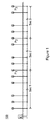
- Fig. 1 is a schematic diagram of configuration of a power cable L of a streetlamp lighting system according to the present invention.
- the streetlamp lighting system according to the present invention has multiple lighting devices electrically connected to the same power cable L, and one total control cabinet is provided at one end of these lighting devices to realize simultaneous automatic or manual electric control of the multiple lighting devices, wherein in order to realize a fault detection device 100 according to the present invention, these multiple lighting devices are functionally divided into several sections, for example, a first section Sec1, a second section Sec2 and a third section Sec3 as shown in Fig. 1 , and the lighting devices are divided into multiple load groups P1, P2, and P3 according to these sections.
- Fig. 1 Refer to Fig.
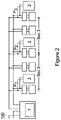
- FIG. 2 shows a schematic diagram of functional structure of the fault detection device 100 of the streetlamp lighting system according to the present invention.
- a load detection control unit 2 at least in the last lighting device in each section, i.e. providing the load detection control unit 2 in a lighting device farthest from the total control cabinet as shown in the circuit in each section, meanwhile, providing a master detection control unit 1 in the total control cabinet, all the lighting devices located between the master detection control unit 1 and the load detection control units 2 in the circuit can be taken as, for instance, a load group, to realize the fault detection and monitor.
- the load detection control units 2 can be electrically connected with drive means and a light source of the lighting devices independently in circuit so as to realize the effect of independent fault detection and monitor.
- Fig. 3 is a schematic diagram of functional structure of respective load detection control unit 2 according to the present invention
- Fig. 4 is a schematic diagram of functional structure of the master detection control unit 1 according to the present invention.
- the load detection control unit 2 according to the present invention comprises a first charging unit C1 configured to be connected with an AC power supply, a first electric energy storage St1 connected with and charged by the first charging unit C1, and an isolated receiver R and an isolated transmitter Tr connected individually with a first control unit MCU1, in addition, the load detection control unit 2 further comprises a first voltage detection unit VD1 configured to detect a power cable voltage state.
- the first voltage detection unit VD1 sends to the first control unit MCU1 a first state detection signal Ss1 according to a detection result of the power cable voltage, so as to inform the first control unit MCU1 of a recognized environmental state of daytime or nighttime, and then, the load detection control unit 2 can modify the fault detection mode according the circumstance so as to ensure normal and stable operation of the whole fault detection device 100, wherein the first voltage detection unit VD1 can determine whether the lighting system is in a daytime or nighttime state by, for instance, detecting whether it is in an AC power supply state, that is, in a situation of the presence of the AC power supply, the lighting system can be recognized as in a nighttime state, and in a situation of absence of the AC power supply but presence of DC power supply, the lighting system can be recognized as in a daytime state.
- the first control unit MCU1 can send to the isolated receiver R a control signal Cti, and receives via the isolated receiver R a first fault detection signal Sti from the master detection control unit 1, and upon processing of the signal, sends via the isolated transmitter Tr a first fault feedback signal Sto to the master detection control unit 1.
- the master detection control unit 1 is configured to comprise a second charging unit C2 in connection with the AC power supply, a second electric energy storage St2 connected with and charged by the second charging unit C2, and an isolated transceiver Ts connected independently with a second control unit MCU2, in addition, the master detection control unit 1 further comprises a second voltage detection unit VD2 and a first current detection unit CD1.
- a wireless communication unit can be further provided in the master detection control unit 1.
- the second voltage detection unit VD2 Similar to the first voltage detection unit VD1 in the load detection control unit 2, the second voltage detection unit VD2 provides a second state detection signal Ss2 to the second control unit MCU2 according to the detected voltage state, and informs the second control unit MCU2 of the recognized environmental state of the lighting system, e.g. daytime or nighttime, so as to realize modification of the fault detection mode, and, for example, in the daytime state, with the aid of the DC power supply IPS, the first fault detection signal Sti is sent via the isolated transceiver Ts to each of the load detection control units 2 in sequence to start the fault detection flow, and the first fault feedback signal Sto from the load detection control unit 2 which runs normally is received via the isolated transceiver Ts.
- the first fault detection signal Sti is sent via the isolated transceiver Ts to each of the load detection control units 2 in sequence to start the fault detection flow, and the first fault feedback signal Sto from the load detection control unit 2 which runs normally is received via the isolated transceiver Ts.
- a total power value of the power cable L can be further obtained so as to finally determine the amount of the lighting devices which run normally and the overall operation state of the lighting system.
- Fig. 5 is a structural schematic diagram of a DC current loop according to the present invention.
- a DC current loop can be formed between the load detection control units 2 and the master detection control unit 1, so as to ensure, for instance, in the daytime state, that the master detection control unit 1 can normally communicate with each load detection control unit 2 in a situation that only a DC power supply supplies the power.
- the DC current loop is comprised of the DC power supply and the isolated transceiver Ts of the master detection control unit 1, and the isolated receivers R and the isolated transmitters Tr of respective load detection control units 2, and an optocoupler, for instance, can be provided between the master detection control unit 1 and each load detection control unit 2, so as to realize electrical isolation between respective different units and ensure the normal and stable operation of the DC current loop.
- the first fault detection signal Sti from the master detection control unit 1 can be sent out and transmitted in the DC current loop, and upon receipt by the isolated receiver R of the corresponding load detection control unit 2, if the operation is normal, the first fault feedback signal Sto is again sent via the isolated transmitter Tr on this DC current loop so as to complete communication interaction between the load detection control unit 2 and the master detection control unit 1.
- Fig. 6 is a schematic diagram of control flow of the control center according to the present invention.
- the control center can warn the operator or monitor according the detection of the master detection control unit 1, for instance, a fault message from the master detection control unit 1 is received via wireless communication, and then, an alarm is sent to the operator so as to finally achieve the function of, for example, anti-theft or warning.
- Fig. 7 is a schematic diagram of control flow of the master detection control unit 1 according to the present invention.
- different fault detection flows are generated according to a daytime or nighttime state after the second voltage detection unit VD2 recognizes whether the lighting system is in the daytime or nighttime environmental state.
- the master detection control unit 1 starts to send the first fault detection signal Sti to each of the load detection control units 2 in a predetermined order.
- Fig. 9 is a signal timing diagram in a fault detection mode during the shift from the nighttime to daytime according to the present invention.
- FIG. 10 is a signal timing diagram in a fault detection mode during the shift from the daytime to nighttime according to the present invention, wherein Fig. 9 and Fig. 10 respectively show the timing diagram of the first fault detection signal Sti and the first fault feedback signals Sto in the master detection control unit 1, and the timing diagrams of the first fault detection signals Sti1, Sti2 and Sti3, the first fault feedback signals Sto1, Sto2 and Sto3 of the load detection control units 2 of the first load group P1, the second load group P2, and the third load group P3, and the control signals Cti1, Cti2 and Cti3 of the second control unit MCU2.
- the first electric energy storage St1 After charged by the first charging unit C1, supplies independently a DC power supply to the master detection control unit 1;
- the timing control from tc2 to tc6 is implemented, the master detection control unit 1 can obtain the electric power directly from the first electric energy storage St1 which has been charged, so as to carry out the fault detection with the aid of the DC current loop.
- the signal is received via the isolated transceiver Ts at the tc4 timing, and keeps for a tc5 timing period, if the first fault feedback signal Sto from the load detection control unit 2 corresponding to the first fault detection signal Sti is received, the master detection control unit 1 changes a pattern included in the first fault detection signal Sti into a pattern corresponding to the next load detection control unit 2 to be detected, and sends out the first fault detection signal Sti; moreover, when the first fault feedback signal Sto from the load detection control unit 2 corresponding to the first fault detection signal Sti is not received, it is determined that a fault occurs, the specific situation, e.g.
- serial number, of the load detection control unit 2 which fails to feed back is determined according to the pattern corresponding to the first fault detection signal Sti which is not fed back, so as to start locating and report to the control center the fault situation, meanwhile, the fault detection process is started again from the first load detection control unit 2, and the amount of the lighting devices which run normally is finally determined.
- Fig. 7 it is also shown in Fig. 7 that, for instance, when a nighttime state is detected according to the second voltage detection unit VD2, similarly, it is determined whether the fault detection device 100 is subject for the first time to, the state shift form the daytime to nighttime, if yes, all fault detection switches are stopped, and it starts to calculate the total power of the power cable L, or if not, it directly starts to calculate the total power of the power cable L to compare it with a historical power value.
- the master detection control unit 1 makes conventional communication with the control center so as to update the detection data.
- Fig. 8 is a schematic diagram of control flow of the load detection control unit 2 according to the present invention.
- the load detection control unit 2 determines, via the isolated receiver R, whether the first fault detection signal Sti from the master detection control unit 1 is received.
- the load detection control unit 2 determines, via the isolated receiver R, whether the first fault detection signal Sti from the master detection control unit 1 is received.
- the timing control from the tp1 is implemented, otherwise, the timing control from tp2 to tp5 is implemented.
- the isolated receiver R receives the first fault detection signal Sti
- the isolated receiver R is stopped for a period of time, and it starts to recognize whether the pattern of the first fault detection signal Sti is consistent with the pattern corresponding to the lighting device.
- the load detection control unit 2 sends, via the isolated transmitter Tr, to the master detection control unit 1 the first fault feedback signal Sto, and after the tp4-tp3-tc3 timing, the isolated receiver R is restarted; if not, the isolated receiver R is re-activated after the tp4 timing.
- Fig. 11 shows a signal timing diagram in the fault detection at the daytime according to the present invention.
- Fig. 12 is a schematic diagram of first fault detection signals sent to different load detection control units 2 according to the present invention.
- the first fault detection signals Sti corresponding to respective the load detection control units 2 can be configured different from each other, and have different or particular patterns, for instance, viewed in the timing, the first fault detection signals Sti corresponding to respective load detection control units 2 can be configured with different timing lengths, that is, the timing length corresponding to the first load group P1 can be less than the timing length corresponding to the second load group P2, and the timing length corresponding to the second load group P2 can be less than the timing length corresponding to the third load group P3.
Landscapes
- Circuit Arrangement For Electric Light Sources In General (AREA)
Claims (20)
- Fehlerdetektionsvorrichtung (100) für ein Straßenlampenbeleuchtungssystem, umfassend mehrere Lastgruppen, die durch ein Stromkabel (L) mit Leistung versorgt werden, dadurch gekennzeichnet, dass die Fehlerdetektionsvorrichtung (100) eine Master-Detektionssteuereinheit (1) und mehrere für jeweilige Lastgruppen ausgelegte Lastdetektionssteuereinheiten (2) umfasst, wobei die Master-Detektionssteuereinheit (1) dazu ausgelegt ist, gemäß einem ersten durch eine jeweilige Lastdetektionssteuereinheit (2) bereitgestellten Fehlerrückmeldungssignal (Sto) zu bestimmen, ob die der Lastdetektionssteuereinheit (2) entsprechende Lastgruppe ausgefallen ist, während sich das Straßenlampenbeleuchtungssystem in einem ersten Zustand befindet; und die Master-Detektionssteuereinheit (1) dazu ausgelegt ist, gemäß einer an dem Stromkabel (L) detektierten physikalischen Größe zu bestimmen, ob das Stromkabel (L) ausgefallen ist, während sich das Straßenlampenbeleuchtungssystem in einem zweiten Zustand befindet, dadurch gekennzeichnet, dass es sich bei dem ersten Zustand um einen Gleichstrom- bzw. DC-Leistungsversorgungszustand des Stromkabels (L) handelt und es sich bei dem zweiten Zustand um einen Wechselstrom- bzw. AC-Leistungsversorgungszustand des Stromkabels (L) handelt.
- Fehlerdetektionsvorrichtung (100) nach Anspruch 1, dadurch gekennzeichnet, dass das Straßenlampenbeleuchtungssystem dazu ausgelegt ist, zu bestimmen, dass die Umgebung in einen ersten Umweltzustand eintritt, gemäß dem ersten Zustand, und bestimmt, dass die Umgebung in einen zweiten Umweltzustand eintritt, gemäß dem zweiten Zustand.
- Fehlerdetektionsvorrichtung (100) nach Anspruch 2, dadurch gekennzeichnet, dass es sich bei dem ersten Umweltzustand um Tag handelt und es sich bei dem zweiten Umweltzustand um Nacht handelt.
- Fehlerdetektionsvorrichtung (100) nach Anspruch 1, dadurch gekennzeichnet, dass die Master-Detektionssteuereinheit (1) dazu ausgelegt ist, das erste Fehlerdetektionssignal (Sti) in dem ersten Zustand nacheinander zu jeder der Lastdetektionssteuereinheit (2) zu senden, um jeweilige erste durch die Lastdetektionssteuereinheiten (2) bereitgestellte Fehlerrückmeldungssignale (Sto) zu erhalten.
- Fehlerdetektionsvorrichtung (100) nach Anspruch 1, dadurch gekennzeichnet, dass es sich bei der physikalischen Größe um eine an dem Stromkabel (L) detektierte Gesamtleistung handelt.
- Fehlerdetektionsvorrichtung (100) nach Anspruch 5, dadurch gekennzeichnet, dass die Master-Detektionssteuereinheit (1) dazu ausgelegt ist, eine aktuelle Gesamtleistung mit einem historischen Leistungswert des Stromkabels (L) in dem zweiten Zustand zu vergleichen, um eine Anzahl der Lastgruppen, die ausgefallen sind, zu bestimmen.
- Fehlerdetektionsvorrichtung (100) nach Anspruch 1, dadurch gekennzeichnet, dass in dem ersten Zustand eine Gleichstrom- bzw. DC-Stromschleife zwischen der Master-Detektionssteuereinheit (1) und den Lastdetektionssteuereinheiten (2) ausgebildet ist.
- Fehlerdetektionsvorrichtung (100) nach Anspruch 1, dadurch gekennzeichnet, dass eine jeweilige Lastdetektionssteuereinheit (2) Folgendes umfasst: eine erste Spannungsdetektionseinheit (VD1), die dazu ausgelegt ist, eine Spannung (Vline) des Stromkabels (L) zu detektieren, um ein erstes Zustandsdetektionssignal (Ssl) bereitzustellen, das den ersten Zustand oder den zweiten Zustand widerspiegelt.
- Fehlerdetektionsvorrichtung (100) nach Anspruch 8, dadurch gekennzeichnet, dass eine jeweilige Lastdetektionssteuereinheit (2) ferner Folgendes umfasst: eine erste Steuereinheit (MCU1), die dazu ausgelegt ist, das erste Zustandsdetektionssignal (Ssl) und das erste Fehlerdetektionssignal (Sti) zu empfangen und das erste Fehlerrückmeldungssignal (Sto) zu erzeugen, wenn ein in dem ersten Fehlerdetektionssignal (Sti) enthaltenes Muster mit einem durch die erste Steuereinheit (MCU1) bereitgestellten Muster übereinstimmt; einen isolierten Empfänger (R), der das erste Fehlerdetektionssignal (Sti) von der Master-Detektionssteuereinheit (1) empfängt und durch das erste Fehlerdetektionssignal (Sti) aktiviert wird; und einen isolierten Sender (Tr), der dazu ausgelegt ist, das erste Fehlerrückmeldungssignal (Sto) zu der Master-Detektionssteuereinheit (1) zu senden.
- Fehlerdetektionsvorrichtung (100) nach Anspruch 9, dadurch gekennzeichnet, dass die isolierten Empfänger (R) oder die isolierten Sender (Tr) jeweiliger Lastdetektionssteuereinheiten (2) mit Optokopplern voneinander getrennt sind.
- Fehlerdetektionsvorrichtung (100) nach Anspruch 9, dadurch gekennzeichnet, dass eine jeweilige Lastdetektionssteuereinheit (2) ferner Folgendes umfasst:einen ersten Speicher (St1) für elektrische Energie, der dazu ausgelegt ist, die erste Steuereinheit (MCU1) und den isolierten Empfänger (R) mit Leistung zu versorgen; undeine erste Ladeeinheit (C1), die dazu ausgelegt ist, den ersten Speicher (St1) für elektrische Energie in einem AC-Leistungsversorgungszustand des Stromkabels (L) zu laden.
- Fehlerdetektionsvorrichtung (100) nach Anspruch 1, dadurch gekennzeichnet, dass die Master-Detektionssteuereinheit (1) Folgendes umfasst: eine zweite Spannungsdetektionseinheit (VD2), die dazu ausgelegt ist, eine Spannung des Stromkabels (L) zu detektieren, um ein zweites Zustandsdetektionssignal (Ss2) bereitzustellen, das den ersten Zustand oder den zweiten Zustand widerspiegelt; und eine erste Stromdetektionseinheit (CD1), die dazu ausgelegt ist, ein Stromsignal (Iline) bereitzustellen, das einen Strom des Stromkabels (L) detektiert.
- Fehlerdetektionsvorrichtung (100) nach Anspruch 12, dadurch gekennzeichnet, dass die Master-Detektionssteuereinheit (1) ferner Folgendes umfasst: eine zweite Steuereinheit (MCU2), die dazu ausgelegt ist, das zweite Zustandsdetektionssignal (Ss2) und das Stromsignal (Iline) zu empfangen, um einen aktuellen Leistungswert des Stromkabels (L) zu bestimmen; und einen isolierten Transceiver (Ts), der dazu ausgelegt ist, das erste Fehlerdetektionssignal (Sti) zu jeweiligen Lastdetektionssteuereinheiten (2) zu senden und die ersten Fehlerrückmeldungssignale (Sto) von den Lastdetektionssteuereinheiten (2) zu empfangen.
- Fehlerdetektionsvorrichtung (100) nach Anspruch 13, dadurch gekennzeichnet, dass die Master-Detektionssteuereinheit (1) ferner Folgendes umfasst:einen zweiten Speicher (St2) für elektrische Energie, der dazu ausgelegt ist, die zweite Steuereinheit (MCU2) und den isolierten Transceiver (Ts) mit Leistung zu versorgen;eine zweite Ladeeinheit (C2), die dazu ausgelegt ist, in einem AC-Leistungsversorgungszustand des Stromkabels (L) geladen zu werden; und eine DC-Leistungsversorgung (IPS), die dazu ausgelegt ist, dem isolierten Transceiver (Ts) eine DC-Leistungsversorgung bereitzustellen.
- Fehlerdetektionsvorrichtung (100) nach Anspruch 14, dadurch gekennzeichnet, dass ein Spannungswert der DC-Leistungsversorgung (IPS) durch die erste Steuereinheit (MCU1) einer jeweiligen Lastdetektionssteuereinheit (2) und die zweite Steuereinheit (MCU2) der Master-Detektionssteuereinheit (1) derart eingestellt wird, dass er niedriger ist als ein Wechselspannungswert in dem AC-Leistungsversorgungszustand.
- Fehlerdetektionsvorrichtung (100) nach Anspruch 7, dadurch gekennzeichnet, dass die DC-Stromschleife aus der DC-Leistungsversorgung (IPS) und dem isolierten Transceiver (Ts) der Master-Detektionssteuereinheit (1) und den isolierten Empfängern (R) und den isolierten Sendern (Tr) jeweiliger Lastdetektionssteuereinheiten (2) besteht.
- Betriebsverfahren einer Fehlerdetektionsvorrichtung (100) für ein Straßenlampenbeleuchtungssystem, umfassend mehrere Lastgruppen, die durch ein Stromkabel (L) mit Leistung versorgt werden, wobei das Verfahren die Folgenden Schritte umfasst:a) Bereitstellen einer Lastdetektionssteuereinheit (2), die dazu ausgelegt ist, eine entsprechende Lastgruppe zu überwachen, und einer Master-Detektionssteuereinheit (1);b) Bestimmen, ob sich das Straßenlampenbeleuchtungssystem in einem ersten Zustand oder einem zweiten Zustand befindet;c) Bestimmen, durch die Master-Detektionssteuereinheit (1), gemäß einem ersten durch die Lastdetektionssteuereinheit (2) bereitgestellten Fehlerrückmeldungssignal (Sto), ob die der Lastdetektionssteuereinheit (2) entsprechende Lastgruppe ausgefallen ist, während sich das Straßenlampenbeleuchtungssystem in dem ersten Zustand befindet; undd) Bestimmen, durch die Master-Detektionssteuereinheit (1), gemäß einer an dem Stromkabel (L) detektierten physikalischen Größe, ob das Stromkabel (L) ausgefallen ist, während sich das Straßenlampenbeleuchtungssystem in dem zweiten Zustand befindet, dadurch gekennzeichnet, dass es sich bei dem ersten Zustand um einen Gleichstrom- bzw. DC-Leistungsversorgungszustand des Stromkabels (L) handelt und es sich bei dem zweiten Zustand um einen Wechselstrom- bzw. AC-Leistungsversorgungszustand des Stromkabels (L) handelt.
- Verfahren nach Anspruch 17, dadurch gekennzeichnet, dass Schritt b) Folgendes umfasst:b1) Detektieren einer Spannung des Stromkabels (L) unter Verwendung einer ersten Spannungsdetektionseinheit (VD1) einer jeweiligen Lastdetektionssteuereinheit (2), um der Lastdetektionssteuereinheit (2) ein erstes Zustandsdetektionssignal (Ssl) bereitzustellen, das den ersten Zustand oder den zweiten Zustand widerspiegelt; undb2) Detektieren einer Spannung des Stromkabels (L) unter Verwendung einer zweiten Spannungsdetektionseinheit (VD2) der Master-Detektionssteuereinheit (1), um der Gesamtlastdetektionssteuereinheit (1) ein zweites Zustandsdetektionssignal (Ss2) bereitzustellen, das den ersten Zustand oder den zweiten Zustand widerspiegelt.
- Verfahren nach Anspruch 18, dadurch gekennzeichnet, dass Schritt c) Folgendes umfasst:c1) Senden, durch die Master-Detektionssteuereinheit (1), eines ersten Fehlerdetektionssignals (Sti) nacheinander an eine jeweilige Lastdetektionssteuereinheit (2);c2) Erzeugen, durch die Lastdetektionssteuereinheit (2), eines ersten Fehlerrückmeldungssignals (Sto), wenn ein in dem ersten Fehlerdetektionssignal (Sti) enthaltenes Muster mit einem Muster der entsprechenden Lastdetektionssteuereinheit (2) übereinstimmt, und Zurücksenden des ersten Fehlerrückmeldungssignals (Sto) zu der Master-Detektionssteuereinheit (1), wobei andernfalls kein erstes Fehlerrückmeldungssignal (Sto) erzeugt wird; undc3) Bestimmen, durch die Master-Detektionssteuereinheit (1), dass die der entsprechenden Lastdetektionssteuereinheit (2) entsprechende Lastgruppe die ausgefallene Lastgruppe ist, wenn bestätigt wird, dass das erste Fehlerrückmeldungssignal (Sto) der entsprechenden Lastdetektionssteuereinheit (2) nicht empfangen wird.
- Verfahren nach Anspruch 18, dadurch gekennzeichnet, dass Schritt d) Folgendes umfasst:d1) Verwenden der ersten Stromdetektionseinheit (CD1) und der zweiten Spannungsdetektionseinheit (VD2) in der Master-Detektionssteuereinheit (1), um eine aktuelle Gesamtleistung des Stromkabels (L) zu berechnen und zu erhalten;d2) Vergleichen, durch die Master-Detektionssteuereinheit (1), der aktuellen Gesamtleistung mit einem historischen Leistungswert des Stromkabels (L); undd3) Bestimmen einer Anzahl der Lastgruppen, die ausgefallen sind, wenn die Differenz zwischen der aktuellen Gesamtleistung und dem historischen Leistungswert des Stromkabels (L) einen vorbestimmten Wert übersteigt.
Applications Claiming Priority (2)
| Application Number | Priority Date | Filing Date | Title |
|---|---|---|---|
| CN201310332023.8A CN104349560B (zh) | 2013-08-01 | 2013-08-01 | 用于路灯照明系统的故障检测装置及其运行方法 |
| PCT/EP2014/066085 WO2015014755A1 (en) | 2013-08-01 | 2014-07-25 | Fault detection device for streetlamp lighting system and method of operating the same |
Publications (2)
| Publication Number | Publication Date |
|---|---|
| EP3028056A1 EP3028056A1 (de) | 2016-06-08 |
| EP3028056B1 true EP3028056B1 (de) | 2020-04-01 |
Family
ID=51225556
Family Applications (1)
| Application Number | Title | Priority Date | Filing Date |
|---|---|---|---|
| EP14744105.9A Active EP3028056B1 (de) | 2013-08-01 | 2014-07-25 | Fehlererkennungsvorrichtung für ein strasssenlampenbeleuchtungssystem und verfahren zum betrieb davon |
Country Status (4)
| Country | Link |
|---|---|
| US (1) | US9648709B2 (de) |
| EP (1) | EP3028056B1 (de) |
| CN (1) | CN104349560B (de) |
| WO (1) | WO2015014755A1 (de) |
Families Citing this family (8)
| Publication number | Priority date | Publication date | Assignee | Title |
|---|---|---|---|---|
| CN104735887B (zh) * | 2015-04-15 | 2017-05-17 | 四川华体照明科技股份有限公司 | 一种路灯漏电自动检测方法 |
| CN105741468A (zh) * | 2016-03-18 | 2016-07-06 | 上海路辉电子科技有限公司 | 一种电缆防盗报警系统及方法 |
| CN107529250B (zh) * | 2017-07-17 | 2019-02-15 | 电子科技大学 | 一种led路灯调控装置及调控方法 |
| CN109884555B (zh) * | 2017-12-06 | 2021-03-19 | 台达电子企业管理(上海)有限公司 | 一种直流集中照明系统及其灯具状态的测量方法 |
| CN108828469B (zh) * | 2018-06-28 | 2024-05-24 | 广州辰创科技发展有限公司 | 一种路灯故障诊断电路及其诊断方法 |
| CN109917211B (zh) * | 2019-03-29 | 2023-12-15 | 江苏核电有限公司 | 一种直流供电模件报警监视装置 |
| CN110133541B (zh) * | 2019-04-30 | 2021-03-23 | 武汉微创光电股份有限公司 | 一种补光灯故障检测方法及装置 |
| CN115226274B (zh) * | 2022-05-11 | 2023-12-19 | 广东柏科电源有限公司 | 一种具有dali功能的恒压led驱动电源负载检测电路和检测方法 |
Citations (1)
| Publication number | Priority date | Publication date | Assignee | Title |
|---|---|---|---|---|
| EP2733836A2 (de) * | 2012-11-16 | 2014-05-21 | Boltier R&D | Wechselstrom-Direktspannungs-Leistungsbooster und Gleichstrom-Wechselstrom-Steuermodul für Gleichstrom-Wechselstrom-Beleuchtungen |
Family Cites Families (12)
| Publication number | Priority date | Publication date | Assignee | Title |
|---|---|---|---|---|
| FR2624335B1 (fr) * | 1987-12-04 | 1990-03-23 | Finzel Jean Luc | Ensemble de detection et de signalisation selectives de defauts de fonctionnement d'unites eclairantes dans un reseau d'eclairage |
| GB9104881D0 (en) * | 1991-03-08 | 1991-04-24 | Ind Cybernetics Ltd | Monitoring apparatus and system |
| US7400062B2 (en) * | 2002-10-15 | 2008-07-15 | Microsemi Corp. - Analog Mixed Signal Group Ltd. | Rack level power management |
| FR2879367B1 (fr) * | 2004-12-14 | 2008-09-26 | Maurice Gainville | Dispositif de commande d'alimentation electrique pour appareils electriques notamment pour candelabres d'eclairage public |
| US7877169B2 (en) * | 2007-08-21 | 2011-01-25 | Electro Industries/ Gauge Tech | System and method for synchronizing an auxiliary electrical generator to an electrical system |
| TW200951347A (en) * | 2008-06-06 | 2009-12-16 | Acbel Polytech Inc | LED road lamp to report the power data in real-time |
| US8475002B2 (en) * | 2009-05-01 | 2013-07-02 | Lighting Science Group Corporation | Sustainable outdoor lighting system and associated methods |
| CA2766807A1 (en) * | 2009-06-25 | 2010-12-29 | Server Technology, Inc. | Power distribution apparatus with input and output power sensing and method of use |
| US8853965B2 (en) * | 2010-02-01 | 2014-10-07 | Twisthink, L.L.C. | Luminary control systems |
| CN101861028A (zh) * | 2010-04-30 | 2010-10-13 | 北京中科富思信息技术有限公司 | 一种路灯故障检测装置、方法和路灯信号发射装置 |
| CN202903939U (zh) * | 2012-10-16 | 2013-04-24 | 四川移盟数码科技有限公司 | 一种基于现场总线网络化的照明线路检测系统 |
| US8907572B2 (en) * | 2012-11-19 | 2014-12-09 | Ting Pat Albert So | Centralized LED based highway lighting supply and controls and related methods |
-
2013
- 2013-08-01 CN CN201310332023.8A patent/CN104349560B/zh active Active
-
2014
- 2014-07-25 EP EP14744105.9A patent/EP3028056B1/de active Active
- 2014-07-25 US US14/909,148 patent/US9648709B2/en active Active
- 2014-07-25 WO PCT/EP2014/066085 patent/WO2015014755A1/en not_active Ceased
Patent Citations (1)
| Publication number | Priority date | Publication date | Assignee | Title |
|---|---|---|---|---|
| EP2733836A2 (de) * | 2012-11-16 | 2014-05-21 | Boltier R&D | Wechselstrom-Direktspannungs-Leistungsbooster und Gleichstrom-Wechselstrom-Steuermodul für Gleichstrom-Wechselstrom-Beleuchtungen |
Also Published As
| Publication number | Publication date |
|---|---|
| CN104349560B (zh) | 2019-05-10 |
| WO2015014755A1 (en) | 2015-02-05 |
| US20160183354A1 (en) | 2016-06-23 |
| US9648709B2 (en) | 2017-05-09 |
| EP3028056A1 (de) | 2016-06-08 |
| CN104349560A (zh) | 2015-02-11 |
Similar Documents
| Publication | Publication Date | Title |
|---|---|---|
| EP3028056B1 (de) | Fehlererkennungsvorrichtung für ein strasssenlampenbeleuchtungssystem und verfahren zum betrieb davon | |
| EP2652444B1 (de) | Verfahren und system zur identifizierung von mindestens einer durch eine stromversorgungsvorrichtung über eine stromleitungsverbindung elektrisch angetriebene vorrichtung | |
| US20190334740A1 (en) | Energy harvesting from fire panel | |
| CN109669441B (zh) | 一种自动断电控制方法、系统及设备 | |
| CN104354669A (zh) | 一种车载远程通信控制器与整车进行安全匹配的方法 | |
| CN102548791A (zh) | 用于控制电驱动的机动车的充电过程的授权的方法和装置 | |
| US12600257B2 (en) | Charger management device and charging control device | |
| JP2019083647A (ja) | 充電通信制御装置及び充電通信制御方法 | |
| KR102347509B1 (ko) | 급속 충전 제어 시스템 및 방법 | |
| DE102017214099A1 (de) | Mobiler Identifikationsgeber | |
| US20160139195A1 (en) | Problem detection in cable system with fuses | |
| US9372744B2 (en) | Method for detecting failure and slave station for use in same | |
| CN202486983U (zh) | 一种道路交通的监控系统 | |
| AU2018374870B2 (en) | Method and apparatus for switching a load between two power sources | |
| JP2014052292A (ja) | 充電施設管理装置及び管理方法 | |
| JP2014529234A (ja) | 設定および/または問合せの目的のための通信方法ならびにそれを実装するシステム | |
| KR20180077531A (ko) | 전기자동차용 충전제어장치 및 이의 통신모드 제어방법 | |
| KR20170110437A (ko) | 무선 전력 전송 모듈 및 이를 이용한 서비스 제공 방법 | |
| JP6141086B2 (ja) | 送電装置、受電装置およびそれらの制御方法、プログラム、および電力伝送システム | |
| CN205468959U (zh) | 一种汽车防盗控制电路 | |
| CN107147085B (zh) | 一种基于智能安全用电系统的无人机立体成像方法 | |
| EP4309162A1 (de) | Fernbedienungsempfangssystem, fahrzeugmontierte steuerungsvorrichtung und autonomes fahrzeug | |
| WO2026068667A1 (en) | Electric vehicle state of charge status | |
| JP2017175727A (ja) | 充電装置 | |
| KR101602547B1 (ko) | 유압발생장치용 비상사태 검출 장치 및 그의 제어방법 |
Legal Events
| Date | Code | Title | Description |
|---|---|---|---|
| PUAI | Public reference made under article 153(3) epc to a published international application that has entered the european phase |
Free format text: ORIGINAL CODE: 0009012 |
|
| 17P | Request for examination filed |
Effective date: 20160301 |
|
| AK | Designated contracting states |
Kind code of ref document: A1 Designated state(s): AL AT BE BG CH CY CZ DE DK EE ES FI FR GB GR HR HU IE IS IT LI LT LU LV MC MK MT NL NO PL PT RO RS SE SI SK SM TR |
|
| AX | Request for extension of the european patent |
Extension state: BA ME |
|
| DAX | Request for extension of the european patent (deleted) | ||
| STAA | Information on the status of an ep patent application or granted ep patent |
Free format text: STATUS: EXAMINATION IS IN PROGRESS |
|
| 17Q | First examination report despatched |
Effective date: 20190208 |
|
| GRAP | Despatch of communication of intention to grant a patent |
Free format text: ORIGINAL CODE: EPIDOSNIGR1 |
|
| STAA | Information on the status of an ep patent application or granted ep patent |
Free format text: STATUS: GRANT OF PATENT IS INTENDED |
|
| INTG | Intention to grant announced |
Effective date: 20191022 |
|
| GRAS | Grant fee paid |
Free format text: ORIGINAL CODE: EPIDOSNIGR3 |
|
| GRAA | (expected) grant |
Free format text: ORIGINAL CODE: 0009210 |
|
| STAA | Information on the status of an ep patent application or granted ep patent |
Free format text: STATUS: THE PATENT HAS BEEN GRANTED |
|
| AK | Designated contracting states |
Kind code of ref document: B1 Designated state(s): AL AT BE BG CH CY CZ DE DK EE ES FI FR GB GR HR HU IE IS IT LI LT LU LV MC MK MT NL NO PL PT RO RS SE SI SK SM TR |
|
| REG | Reference to a national code |
Ref country code: GB Ref legal event code: FG4D |
|
| REG | Reference to a national code |
Ref country code: CH Ref legal event code: EP Ref country code: AT Ref legal event code: REF Ref document number: 1252077 Country of ref document: AT Kind code of ref document: T Effective date: 20200415 |
|
| REG | Reference to a national code |
Ref country code: DE Ref legal event code: R096 Ref document number: 602014063147 Country of ref document: DE |
|
| REG | Reference to a national code |
Ref country code: IE Ref legal event code: FG4D |
|
| PG25 | Lapsed in a contracting state [announced via postgrant information from national office to epo] |
Ref country code: BG Free format text: LAPSE BECAUSE OF FAILURE TO SUBMIT A TRANSLATION OF THE DESCRIPTION OR TO PAY THE FEE WITHIN THE PRESCRIBED TIME-LIMIT Effective date: 20200701 |
|
| REG | Reference to a national code |
Ref country code: NL Ref legal event code: MP Effective date: 20200401 |
|
| REG | Reference to a national code |
Ref country code: LT Ref legal event code: MG4D |
|
| RAP2 | Party data changed (patent owner data changed or rights of a patent transferred) |
Owner name: OSRAM GMBH |
|
| PG25 | Lapsed in a contracting state [announced via postgrant information from national office to epo] |
Ref country code: NL Free format text: LAPSE BECAUSE OF FAILURE TO SUBMIT A TRANSLATION OF THE DESCRIPTION OR TO PAY THE FEE WITHIN THE PRESCRIBED TIME-LIMIT Effective date: 20200401 Ref country code: LT Free format text: LAPSE BECAUSE OF FAILURE TO SUBMIT A TRANSLATION OF THE DESCRIPTION OR TO PAY THE FEE WITHIN THE PRESCRIBED TIME-LIMIT Effective date: 20200401 Ref country code: NO Free format text: LAPSE BECAUSE OF FAILURE TO SUBMIT A TRANSLATION OF THE DESCRIPTION OR TO PAY THE FEE WITHIN THE PRESCRIBED TIME-LIMIT Effective date: 20200701 Ref country code: FI Free format text: LAPSE BECAUSE OF FAILURE TO SUBMIT A TRANSLATION OF THE DESCRIPTION OR TO PAY THE FEE WITHIN THE PRESCRIBED TIME-LIMIT Effective date: 20200401 Ref country code: GR Free format text: LAPSE BECAUSE OF FAILURE TO SUBMIT A TRANSLATION OF THE DESCRIPTION OR TO PAY THE FEE WITHIN THE PRESCRIBED TIME-LIMIT Effective date: 20200702 Ref country code: IS Free format text: LAPSE BECAUSE OF FAILURE TO SUBMIT A TRANSLATION OF THE DESCRIPTION OR TO PAY THE FEE WITHIN THE PRESCRIBED TIME-LIMIT Effective date: 20200801 Ref country code: SE Free format text: LAPSE BECAUSE OF FAILURE TO SUBMIT A TRANSLATION OF THE DESCRIPTION OR TO PAY THE FEE WITHIN THE PRESCRIBED TIME-LIMIT Effective date: 20200401 Ref country code: CZ Free format text: LAPSE BECAUSE OF FAILURE TO SUBMIT A TRANSLATION OF THE DESCRIPTION OR TO PAY THE FEE WITHIN THE PRESCRIBED TIME-LIMIT Effective date: 20200401 Ref country code: PT Free format text: LAPSE BECAUSE OF FAILURE TO SUBMIT A TRANSLATION OF THE DESCRIPTION OR TO PAY THE FEE WITHIN THE PRESCRIBED TIME-LIMIT Effective date: 20200817 |
|
| REG | Reference to a national code |
Ref country code: AT Ref legal event code: MK05 Ref document number: 1252077 Country of ref document: AT Kind code of ref document: T Effective date: 20200401 |
|
| PG25 | Lapsed in a contracting state [announced via postgrant information from national office to epo] |
Ref country code: LV Free format text: LAPSE BECAUSE OF FAILURE TO SUBMIT A TRANSLATION OF THE DESCRIPTION OR TO PAY THE FEE WITHIN THE PRESCRIBED TIME-LIMIT Effective date: 20200401 Ref country code: RS Free format text: LAPSE BECAUSE OF FAILURE TO SUBMIT A TRANSLATION OF THE DESCRIPTION OR TO PAY THE FEE WITHIN THE PRESCRIBED TIME-LIMIT Effective date: 20200401 Ref country code: HR Free format text: LAPSE BECAUSE OF FAILURE TO SUBMIT A TRANSLATION OF THE DESCRIPTION OR TO PAY THE FEE WITHIN THE PRESCRIBED TIME-LIMIT Effective date: 20200401 |
|
| PG25 | Lapsed in a contracting state [announced via postgrant information from national office to epo] |
Ref country code: AL Free format text: LAPSE BECAUSE OF FAILURE TO SUBMIT A TRANSLATION OF THE DESCRIPTION OR TO PAY THE FEE WITHIN THE PRESCRIBED TIME-LIMIT Effective date: 20200401 |
|
| REG | Reference to a national code |
Ref country code: DE Ref legal event code: R097 Ref document number: 602014063147 Country of ref document: DE |
|
| PG25 | Lapsed in a contracting state [announced via postgrant information from national office to epo] |
Ref country code: IT Free format text: LAPSE BECAUSE OF FAILURE TO SUBMIT A TRANSLATION OF THE DESCRIPTION OR TO PAY THE FEE WITHIN THE PRESCRIBED TIME-LIMIT Effective date: 20200401 Ref country code: DK Free format text: LAPSE BECAUSE OF FAILURE TO SUBMIT A TRANSLATION OF THE DESCRIPTION OR TO PAY THE FEE WITHIN THE PRESCRIBED TIME-LIMIT Effective date: 20200401 Ref country code: SM Free format text: LAPSE BECAUSE OF FAILURE TO SUBMIT A TRANSLATION OF THE DESCRIPTION OR TO PAY THE FEE WITHIN THE PRESCRIBED TIME-LIMIT Effective date: 20200401 Ref country code: EE Free format text: LAPSE BECAUSE OF FAILURE TO SUBMIT A TRANSLATION OF THE DESCRIPTION OR TO PAY THE FEE WITHIN THE PRESCRIBED TIME-LIMIT Effective date: 20200401 Ref country code: AT Free format text: LAPSE BECAUSE OF FAILURE TO SUBMIT A TRANSLATION OF THE DESCRIPTION OR TO PAY THE FEE WITHIN THE PRESCRIBED TIME-LIMIT Effective date: 20200401 Ref country code: ES Free format text: LAPSE BECAUSE OF FAILURE TO SUBMIT A TRANSLATION OF THE DESCRIPTION OR TO PAY THE FEE WITHIN THE PRESCRIBED TIME-LIMIT Effective date: 20200401 Ref country code: RO Free format text: LAPSE BECAUSE OF FAILURE TO SUBMIT A TRANSLATION OF THE DESCRIPTION OR TO PAY THE FEE WITHIN THE PRESCRIBED TIME-LIMIT Effective date: 20200401 |
|
| PLBE | No opposition filed within time limit |
Free format text: ORIGINAL CODE: 0009261 |
|
| STAA | Information on the status of an ep patent application or granted ep patent |
Free format text: STATUS: NO OPPOSITION FILED WITHIN TIME LIMIT |
|
| PG25 | Lapsed in a contracting state [announced via postgrant information from national office to epo] |
Ref country code: SK Free format text: LAPSE BECAUSE OF FAILURE TO SUBMIT A TRANSLATION OF THE DESCRIPTION OR TO PAY THE FEE WITHIN THE PRESCRIBED TIME-LIMIT Effective date: 20200401 Ref country code: PL Free format text: LAPSE BECAUSE OF FAILURE TO SUBMIT A TRANSLATION OF THE DESCRIPTION OR TO PAY THE FEE WITHIN THE PRESCRIBED TIME-LIMIT Effective date: 20200401 Ref country code: MC Free format text: LAPSE BECAUSE OF FAILURE TO SUBMIT A TRANSLATION OF THE DESCRIPTION OR TO PAY THE FEE WITHIN THE PRESCRIBED TIME-LIMIT Effective date: 20200401 |
|
| REG | Reference to a national code |
Ref country code: CH Ref legal event code: PL |
|
| 26N | No opposition filed |
Effective date: 20210112 |
|
| GBPC | Gb: european patent ceased through non-payment of renewal fee |
Effective date: 20200725 |
|
| REG | Reference to a national code |
Ref country code: BE Ref legal event code: MM Effective date: 20200731 |
|
| PG25 | Lapsed in a contracting state [announced via postgrant information from national office to epo] |
Ref country code: LU Free format text: LAPSE BECAUSE OF NON-PAYMENT OF DUE FEES Effective date: 20200725 Ref country code: FR Free format text: LAPSE BECAUSE OF NON-PAYMENT OF DUE FEES Effective date: 20200731 Ref country code: CH Free format text: LAPSE BECAUSE OF NON-PAYMENT OF DUE FEES Effective date: 20200731 Ref country code: GB Free format text: LAPSE BECAUSE OF NON-PAYMENT OF DUE FEES Effective date: 20200725 Ref country code: LI Free format text: LAPSE BECAUSE OF NON-PAYMENT OF DUE FEES Effective date: 20200731 |
|
| PG25 | Lapsed in a contracting state [announced via postgrant information from national office to epo] |
Ref country code: SI Free format text: LAPSE BECAUSE OF FAILURE TO SUBMIT A TRANSLATION OF THE DESCRIPTION OR TO PAY THE FEE WITHIN THE PRESCRIBED TIME-LIMIT Effective date: 20200401 Ref country code: BE Free format text: LAPSE BECAUSE OF NON-PAYMENT OF DUE FEES Effective date: 20200731 |
|
| PG25 | Lapsed in a contracting state [announced via postgrant information from national office to epo] |
Ref country code: IE Free format text: LAPSE BECAUSE OF NON-PAYMENT OF DUE FEES Effective date: 20200725 |
|
| PG25 | Lapsed in a contracting state [announced via postgrant information from national office to epo] |
Ref country code: TR Free format text: LAPSE BECAUSE OF FAILURE TO SUBMIT A TRANSLATION OF THE DESCRIPTION OR TO PAY THE FEE WITHIN THE PRESCRIBED TIME-LIMIT Effective date: 20200401 Ref country code: MT Free format text: LAPSE BECAUSE OF FAILURE TO SUBMIT A TRANSLATION OF THE DESCRIPTION OR TO PAY THE FEE WITHIN THE PRESCRIBED TIME-LIMIT Effective date: 20200401 Ref country code: CY Free format text: LAPSE BECAUSE OF FAILURE TO SUBMIT A TRANSLATION OF THE DESCRIPTION OR TO PAY THE FEE WITHIN THE PRESCRIBED TIME-LIMIT Effective date: 20200401 |
|
| PG25 | Lapsed in a contracting state [announced via postgrant information from national office to epo] |
Ref country code: MK Free format text: LAPSE BECAUSE OF FAILURE TO SUBMIT A TRANSLATION OF THE DESCRIPTION OR TO PAY THE FEE WITHIN THE PRESCRIBED TIME-LIMIT Effective date: 20200401 |
|
| REG | Reference to a national code |
Ref country code: DE Ref legal event code: R081 Ref document number: 602014063147 Country of ref document: DE Owner name: INVENTRONICS GMBH, DE Free format text: FORMER OWNER: OSRAM GMBH, 80807 MUENCHEN, DE |
|
| REG | Reference to a national code |
Ref country code: DE Ref legal event code: R081 Ref document number: 602014063147 Country of ref document: DE Owner name: INVENTRONICS GMBH, DE Free format text: FORMER OWNER: OPTOTRONIC GMBH, 85748 GARCHING, DE |
|
| PGFP | Annual fee paid to national office [announced via postgrant information from national office to epo] |
Ref country code: DE Payment date: 20250722 Year of fee payment: 12 |