EP3028065B1 - Procédé et système de détermination d'un emplacement d'un diffuseur réfléchissant dans un milieu - Google Patents
Procédé et système de détermination d'un emplacement d'un diffuseur réfléchissant dans un milieu Download PDFInfo
- Publication number
- EP3028065B1 EP3028065B1 EP14832223.3A EP14832223A EP3028065B1 EP 3028065 B1 EP3028065 B1 EP 3028065B1 EP 14832223 A EP14832223 A EP 14832223A EP 3028065 B1 EP3028065 B1 EP 3028065B1
- Authority
- EP
- European Patent Office
- Prior art keywords
- interferometric
- complex
- signal
- samples
- interferometric beam
- Prior art date
- Legal status (The legal status is an assumption and is not a legal conclusion. Google has not performed a legal analysis and makes no representation as to the accuracy of the status listed.)
- Not-in-force
Links
Images

Classifications
-
- G—PHYSICS
- G01—MEASURING; TESTING
- G01S—RADIO DIRECTION-FINDING; RADIO NAVIGATION; DETERMINING DISTANCE OR VELOCITY BY USE OF RADIO WAVES; LOCATING OR PRESENCE-DETECTING BY USE OF THE REFLECTION OR RERADIATION OF RADIO WAVES; ANALOGOUS ARRANGEMENTS USING OTHER WAVES
- G01S15/00—Systems using the reflection or reradiation of acoustic waves, e.g. sonar systems
- G01S15/02—Systems using the reflection or reradiation of acoustic waves, e.g. sonar systems using reflection of acoustic waves
- G01S15/06—Systems determining the position data of a target
- G01S15/42—Simultaneous measurement of distance and other co-ordinates
-
- G—PHYSICS
- G01—MEASURING; TESTING
- G01S—RADIO DIRECTION-FINDING; RADIO NAVIGATION; DETERMINING DISTANCE OR VELOCITY BY USE OF RADIO WAVES; LOCATING OR PRESENCE-DETECTING BY USE OF THE REFLECTION OR RERADIATION OF RADIO WAVES; ANALOGOUS ARRANGEMENTS USING OTHER WAVES
- G01S7/00—Details of systems according to groups G01S13/00, G01S15/00, G01S17/00
- G01S7/52—Details of systems according to groups G01S13/00, G01S15/00, G01S17/00 of systems according to group G01S15/00
- G01S7/523—Details of pulse systems
- G01S7/526—Receivers
Definitions
- the invention relates to the field of wave propagation in mediums and determining the location of a reflecting scatterer in a medium.
- the scatterer may be a single particle or discontinuity, or may be a plurality of reflecting particles or discontinuities.
- the scatterer may also be an extended (1D or 2D) discontinuity or interface in the medium.
- the scatterer should thus be understood, in general fashion, as any element in the medium, or any portion of the medium, able to reflect a wave propagating in the medium.
- the invention is related to methods and systems for determining the location of such a scatterer.
- the invention is also related to methods and systems for determining a displacement or change in orientation of said scatterer.
- the invention can find applications in the fields of bathymetry, obstacle avoidance sonars, non-destructive testing of materials, medical imaging such as such as medical echography, mobile probe position calibration and more generally in every field where a reflecting scatterer in a medium has to be located in an efficient and reliable way.
- the wave is an acoustic wave, but the invention may also be applied to electro-magnetic waves.
- High resolution imaging techniques are known but are marginally qualified for these tasks because of their large computational cost and the fact that distributions of the scatterers usually do not fit the problem of resolving a finite number of closely spaced reflectors.
- SAIT Sub-Array Interferometric Techniques
- measurements are performed by transmitting a wave with an across-track fan geometry covering typically more than a 90°-wide sector.
- the reflected wave is acquired with a receiving antenna having a large array of transducers.
- An example of suitable acquisition system is for instance a "Multi-Beam Echo-Sounders" (MBES).
- MBES Multi-Beam Echo-Sounders
- the array of transducers is divided into two sub-arrays.
- a pair of beams focused in the same direction can then be formed by combining the properly synchronized respective signals of these respective sub-arrays (sometimes called beamforming), thus giving two sets of focused samples ⁇ x k ⁇ and ⁇ y k ⁇ where k are the respective indexes of transducers elements in the associated sub-arrays.
- the complex interferometric estimator Y ( t, ⁇ ) can be mapped as a sectorial image made of a collection of beams where the range is associated with time and the angle is associated with the directions of the beams.
- the interferometric estimator Y is made of echoes whose origin sweeps the reflecting scatterer around the beam axis.
- the soundings are thus determined at fixed directions ⁇ by deriving the range from a linear regression of said phase ramp ⁇ ⁇ ( t ) in a proper time window.
- the SAIT methods show several drawbacks.
- the relation between the complex phase of the interferometric estimator Y and the direction of arrival of the received echo ⁇ ( ⁇ ) is multivalued, the complex phase having an ambiguity modulo 2 ⁇ .
- the interferometric estimator Y is not normalized and the phase ramps have thus to be detected by using miscellaneous tricks, mostly based on the magnitude of echoes, continuity of the tracked profile within the ping and inter-pings. These tricks are frequently not fully reliable and/or are based on too restrictive assumption (e.g. no more than one single interface in each direction).
- such a method for determining a location of a reflecting scatterer in a medium comprises:
- the invention also has as an object a system for determining a location of a reflecting scatterer in a medium, comprising:
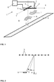
- Figure 1 illustrates a system 1 for determining a location of a reflecting scatterer S in a medium M according to one embodiment of the invention.
- System 1 comprises a transmit array 2 and a receive array 3.
- the transmit array 2 and the receive array 3 can for instance be part of an echo-sounder such as a "Multi-Beam Echo-Sounders” (MBES).
- MBES Multi-Beam Echo-Sounders
- the transmit array 2 can comprise one transducer 4 or can comprise several transducers 4 that may then be juxtaposed, for example in a linear array extending along a longitudinal axis X.
- the transducers 4 of transmit array 2 are able to emit a transmit wave T in the medium M.
- Transmit wave T may have a central frequency that belongs to an acoustic propagation frequency window of the medium, for instance between 10 kHz and 800 kHz for a medium like water, for example in the range 30-34 kHz. In the case of a more solid medium such as a body or tissues, transmit wave T may have a higher central frequency, for instance of the order of several MHz, for instance 2 MHz.
- the transducer 4 can emit several successive transmit waves T, usually called ping.
- the transmit waves T may be temporally delimited with boxcar envelopes and temporally separated one from the other by delays.
- transmit array 2 may thus transmits a sequence of several transmit waves T in the range 30-34 kHz with boxcar envelopes of several milliseconds duration each, and several milliseconds delay between the successive transmit waves T, this example not being limitative.
- a radial resolution of system 1 can thus be determined and may be, in the above example, of a few meters.
- Each transmit wave T may cover a disjoint angular sector of the medium.
- the width of each angular sector may vary between 10° and 20°.
- the total aperture of the system in the medium may be over 90°, or even over 100°, for instance over 140°.
- Each transmit wave T is at least partly reflected by the reflecting scatterer S of the medium thus forming a reflected wave R.
- a method for determining a location of a reflecting scatterer S in a medium M can comprise a transmitting step (a) in which at least one of said transducers 4 emits said transmit wave T in the medium M, said transmit wave T being then reflected in part by a reflecting scatterer S in the medium to form a reflected wave R.
- the reflected wave R is then acquired by receive array 3.
- Receive array 3 comprises n transducers 5. Said n transducers 5 may for instance be juxtaposed, for example along a transversal axis Y, to form a linear array 3. Transversal axis Y may for instance be an axis perpendicular to longitudinal axis X as illustrated on figure 1 .
- Receive array 3 may have a more complex geometry and, for instance, may form a bidimensional or tridimensional array 3. Said n transducers 5 may thus be juxtaposed along two or three perpendicular axis. Said transducers 5 may for instance be arranged in a horizontal plan X, Y. In this case the results of a method according to the invention may be used to determine projections along several vertical planes X, Z and Y, Z.
- Receive array 3 can conveniently extend, in at least one direction (for example transversal axis Y), over a length L large with regard to a central wavelength of the transmit wave T in the medium M, for instance over a length at least several times higher than said central wavelength.
- receive array 3 can provide a high selectivity in elevation.
- receive array 3 may extend over a length of over one meter, i.e. over thirty times higher the central wavelength of the transmit wave T in the medium M.
- length of an array it is meant a distance separating two transducers of the array, in particular two transducers located at two opposite end of said array along a direction of extension of the array.
- each transducer of the array being separated from its neighbours by a distance d , the length of the array is thus the product of the number of transducers n by the separating distance d .
- Each transducer i of the array 3 provides a transducer signal s i that comprises a time series of samples s i (t) acquired in response to the reflected wave R.
- the n transducer signals s 1 , ..., s n are then processed to determine a location of the reflecting scatterer S in the medium M.
- System 1 also comprises a processor 6 that may for instance be adapted and/or programmed to perform step of the a method according to the invention and in particular a beamforming step (c), an interferometric processing step (d) and a location determining step (e) that will now be described in more details.
- a processor 6 may for instance be adapted and/or programmed to perform step of the a method according to the invention and in particular a beamforming step (c), an interferometric processing step (d) and a location determining step (e) that will now be described in more details.
- n beamformed signals x 1 , ..., x n are computed by synchronizing the n transducers signals s 1 , ..., s n in a predetermined spatial direction ⁇ relative to the array of transducers as illustrated on figure 2 .
- Said beamforming step can for instance be performed by applying specific time delays to the beamformed signals x 1 , ..., x n .
- the predetermined spatial direction ⁇ relative to the array 3 of transducers 5 thus defines a beam axis direction of a beam formed by the n beamformed signals x 1 , ..., x n .
- Beamforming methods are known in the field of signal processing and will not be described in greater length hereafter. Suffice to say that the particular focusing method selected for the beamforming step can be in general any of such known beamforming techniques.
- a method according to the invention further comprises an interferometric processing step (d).
- a complex interferometric signal C comprising a time series of interferometric beam samples C(t) is determined.
- Said complex interferometric signal C is a function of at least one product x i x j * of a beamformed signal x i and a conjugate of a beamformed signal x j , with 1 ⁇ i, j ⁇ n.
- the complex interferometric signal C can be determined by normalizing an interferometric estimator by a total power received by the n transducers.
- the modulus of the complex interferometric signal C is less than a predefined maximal modulus for each element of the time series of interferometric beam samples C(t).
- Said predefined maximal modulus may be equal to unity and will be described in greater details further below.
- the complex interferometric signal C can then be obtained by normalizing said interferometric estimator Q by the mean power E 2 received by the array of n transducers.
- Said mean power E 2 is actually the trace of said matrix R, that may be normalized by the number n of transducers.
- the complex interferometric signal C is thus a function of a sum of the whole upper right triangle, excluding a main diagonal, of said matrix R.
- the complex estimator Q can be determined by computing an interferometric signal sum S n-1 and dividing said sum S n-1 by a normalisation coefficient n(n-1) / 2.
- the interferometric signal sum S n-1 can be determined recursively by performing the following operations.
- a sum element c 0 and an interferometric signal sum S 0 are initialised to zero.
- the beamformed signals x 1 , ..., x n and the products x i x j * involved in the above mentioned estimators may also be time averaged, in particular time averaged in a window centered on the focus point of the beamformed beam.
- a location determining step (e) can be performed.
- At least one interferometric beam sample C(t s ) is selected from the complex interferometric signal C.
- several interferometric beam samples C ( t s ) are selected.
- the interferometric beam samples C(t s ) are indicative of a location of the reflecting scatterer or scatterers S.
- the interferometric beam samples C(t s ) may correspond to coherent echoes coming from said scatterer.
- the interferometric beam samples C(t s ) are selected based on a complex argument of said selected interferometric beam sample C ( t s ).
- Such a selection may be performed as follows.
- a one-to-one correspondence ⁇ ( ⁇ ) may exist between a complex argument ⁇ of interferometric signal C and a viewing angle ⁇ of the reflecting scatterer S relative to the predetermined spatial direction ⁇ .
- This one-to-one correspondence ⁇ ( ⁇ ) may in particular exists only for a predefined range
- Interferometric beam samples C(t s ) may thus be selected by selecting interferometric beam samples C(t s ) whose complex arguments ⁇ belong to the predefined range
- said one-to-one correspondence ⁇ ( ⁇ ) and said predefined upper threshold ⁇ 0 may be determined from the geometry of the receive array 3. More precisely, the one-to-one correspondence may depend on the location X k of the transducers 5 along receive array 3.
- the one-to-one correspondence between the complex argument of interferometric signal C and the viewing angle may thus be determined by computing a complex interferometric signal C as described above, starting from theoretical beamformed signals x 1 , ..., x n corresponding to a farfield point source at a predefined viewing angle ⁇ .
- the predefined upper threshold ⁇ 0 may be determined by plotting the complex argument of interferometric signal C as a function of viewing angle ⁇ as illustrated on figure 3B .
- the predefined upper threshold ⁇ 0 can for instance be determined as ⁇ 0 ⁇ 1.35 for a regularly spaced transducer array 3.
- a predefined range of complex argument values for the selected interferometric beam samples C(t s ) may be comprised between -1.35 and 1.35.
- the predefined upper threshold ⁇ 0 may be a function of the number n of transducers.
- Figures 3A and 3B illustrates an example of such a one-to-one correspondence computed for a regularly spaced transducers array.
- interferometric beam samples C ( t s ) may be selected by selecting interferometric beam samples C ( t s ) whose complex arguments ⁇ belong to a smaller range than the above described predefined range
- interferometric beam samples C(t s ) may be selected by selecting interferometric beam samples C(t s ) whose complex arguments ⁇ belong to a range predefined to avoid redundancy between neighbouring beams, for instance a range
- FIG 4B This embodiment of the invention is illustrated on figure 4B on which complex arguments ⁇ of selected interferometric beam samples C(t s ) belong to a reduced range of about
- the location of scatterer S may be determined in terms of viewing angle and distance in a very simple way by performing a polar migration.
- the viewing angle ⁇ of the scatterer with reference to the predetermined spatial direction ⁇ of the beam can be determined from the complex argument of the interferometric beam samples C(t s ) as detailed above and illustrated on figure 2 .
- the distance r of the scatterer along the direction given by viewing angle ⁇ can be computed from the time of arrival of the reflected wave t s , taking into account the speed of the wave in the medium.
- the interferometric beam samples C(t s ) are thus indicative of a location of the reflecting scatterer.
- the location determining step (e) may also comprise an operation of selecting interferometric beam samples from the complex interferometric signal C, whose modulus are higher than a predefined modulus threshold as illustrated on figure 4B .
- This operation may increase the signal over noise ratio by selecting only interferometric beam samples which correspond to coherent reflection of the transmit wave T onto the reflecting scatterer S.
- coherent reflection it is meant a reflected wave R that lead to coherent interferences when acquired by the receive array 3 of transducers 5.
- of the complex interferometric signal C may be theoretically or experimentally predetermined as a modulus of the complex interferometric signal C in response to a single off-axis scatterer.
- may depend on the complex argument ⁇ of the complex interferometric signal C.
- Normalized coherence factor R may for instance be defined in said predefined range of complex argument
- ⁇ arg C
- Normalized coherence factor R may have a modulus comprised between zero and one.
- a predefined modulus threshold f may then be defined as a fraction of said predefined maximal modulus
- a predefined modulus threshold may for instance be equal to 0.1 times said predefined maximal modulus, or 0.3 times said predefined maximal modulus.
- the predefined modulus threshold may be higher for instance equal to 0.8 or 0.9 times said predefined maximal modulus.
- the method according to the invention may further comprise a soundings determination step (f) during which a plurality of soundings are determined on the basis of the selected interferometric beam samples C(ts).
- a sounding it is in particular meant a measured depth of water over a specific point of a seabed as known in the field of bathymetry.
- the selected interferometric beam samples C(t s ) may correspond to several scatterers and the soundings determination step aims in particular at merging together all the interferometric beam samples C(t s ) that correspond to a same scatterer, in particular the interferometric beam samples C(t s ) in polar coordinates as detailed above.
- the plurality of soundings may for instance be determined by repeatedly merging at least two closest interferometric beam samples of the selected interferometric beam samples, until a minimal distance, being a distance separating two closest interferometric beam samples of the selected interferometric beam samples, is higher than a predefined minimal distance threshold.
- the selected interferometric beam samples are first converted, or migrated, in polar units, as detailed above, by computing polar coordinates comprising a distance r k and an angle ⁇ k of each scatterer associated to a selected interferometric beam sample k .
- Said polar coordinates may for instance be defined in relation to the location and orientation of the receive array 3 of transducers 5.
- the polar coordinates are then rescaled with predefined radial and angular resolutions ⁇ r, ⁇ (L2-norm).
- At least two closest interferometric beam samples of the selected interferometric beam samples are then replaced by their barycenter.
- close interferometric beam samples it is understood the closest interferometric beam samples according to a distance provided by the L2-norm on the rescaled polar coordinates of the interferometric beam samples C(t s ).
- the barycenter is an interferometric beam sample defined by weighting each of said closest interferometric beam samples with a barycentric weight function of the modulus of the complex interferometric signal C or of the modulus of the normalized coherence factor R.
- the barycentric weight barycenter is a function of a sum of the barycentric weights of each of said closest interferometric beam samples.
- An additional weight may be associated to the obtained barycenter.
- the additional weight of the barycenter may be a function of the modulus of the complex interferometric signal C or of the modulus of the normalized coherence factor R of said closest interferometric beam samples.
- This additional weight may be computed as a function of the normalized coherence factor R of the merged closest interferometric beam samples, for instance a sum, a maximum. It may also be a more general function of said closest interferometric beam samples, and in a general fashion, any commutative function, i.e. any function independent of the order of its arguments may be employed.
- a commutative function may gives results comprised between a sum of the arguments and a maximum of the arguments.
- Said predefined minimal distance threshold can typically be less than a few units of said L2-norm distance.
- a set of sounding can then be determined from the resulting set of interferometric beam samples by converting the polar coordinates of each interferometric beam samples in an associated depth of water.
- Barycentric or additional weights associated to the interferometric beam samples may be used in following processes, in particular as weighting factors, for instance to construct a numerical model of a seabed taking into account sounding with associated quality factors.
- a numerical model may for instance be constructed by performing a method such as the " Combined Uncertainty and Bathymetry Estimator” (CUBE) detailed for example in "Automatic Statistical Processing of Multibeam Echosounder Data” published by Calder B.R. in International Hydrographic Review, Vol. 4, No 1, pp 16, 2003 .
- the above mentioned factors ⁇ Y and ⁇ Y may also be used to determine such weighting factors.
- the method according to the invention may further comprise a receiving array optimizing step (g) wherein n calibration factors associated to the receive array 3 of n transducers 5 are determined.
- the calibration factors are complex numbers.
- Each calibration factors thus have a complex argument, or phase, and a modulus that can be adjusted during the minimization.
- Each calibration factor i is associated with a respective transducer i of the receive array 3 and weights the time series of samples S i (t) acquired by said transducer i.
- the n calibration factors may be determined by minimizing a cost function.
- the cost function may function of an average distance of the modulus of selected interferometric beam samples C(t s ) with a predefined maximal modulus.
- the predefined maximal modulus may in particular be function of the complex argument of the selected interferometric beam sample C(t s ) .
- predefined maximal modulus is the above mentioned predefined maximal modulus
- the cost function is minimized using known minimization algorithms.
- the n calibration factors may be initialized to unity before performing the minimization of the cost function.
- Constrains must be applied on the set of n calibration factors.
- the mean modulus of the n calibration factors may be kept constant during the minimization.
- the mean complex argument, or phase, of the n calibration factors may be kept constant during the minimization and, for instance equal to zero.
- the mean slope of calibration factor phase versus transducer index may be kept constant and, for instance, equal to zero.
- the method according to the invention may further comprise a displacement determining step (h).
- the series of steps (a-e) of transmitting, receiving, beamforming, interferometric processing and location determining may be performed sequentially several times to obtain several sets of selected interferometric beam samples C i (t s ) associated to the emission of several successive transmit waves T and the processing of transducer signals corresponding to the associated several successive reflected waves R.
- the series of steps (a-e) may be performed at least a first and a second successive time to obtain first interferometric beam samples C 1 (t s ) and second interferometric beam samples C 2 (t s ).
- a displacement determining step (h) is then performed following said iterations of steps (a-e).
- a scatterer displacement value is determined as a function of the sets of selected interferometric beam samples C i (t s ) corresponding to successive transmit waves T i .
- scatterer displacement value a value indicative of a displacement, rotation and/or deformation of scatterer S between said successive transmit waves T i , said displacement, rotation and/or deformation being in particular considered in a coordinate system associated to the receiving array 3.
- a normalized product ⁇ i,j may be computed on the basis on the normalized coherence factors R as detailed above, for instance by computing product R i .R i +1 *.
- the obtained set of products ⁇ i,j may be filtered by selecting product ⁇ i,j whose modulus are higher than a predefined product modulus threshold, in a similar manner to the above mentioned selection of interferometric beam samples from the complex interferometric signal C based on their modulus.
- a scatterer displacement value or a set of scatterer displacement values may then be computed as a function of a complex argument, a phase and/or a modulus of computed products ⁇ i , j .
- the complex argument of product ⁇ i,j can be used to give a scatterer displacement value indicative of the rotation between the first and second acquisitions.
- this time between the complex argument of product ⁇ i,j and the rotation angle between the first and second acquisitions.
Landscapes
- Engineering & Computer Science (AREA)
- Physics & Mathematics (AREA)
- Radar, Positioning & Navigation (AREA)
- Remote Sensing (AREA)
- Computer Networks & Wireless Communication (AREA)
- General Physics & Mathematics (AREA)
- Acoustics & Sound (AREA)
- Measurement Of Velocity Or Position Using Acoustic Or Ultrasonic Waves (AREA)
- Investigating Or Analyzing Materials By The Use Of Ultrasonic Waves (AREA)
Claims (14)
- Procédé de détermination d'un emplacement d'un diffuseur réfléchissant (S) dans un milieu (M), le procédé comprenant :- une étape de transmission (a) dans laquelle au moins un transducteur (4) émet une onde de transmission (T) dans un milieu (M), ladite onde de transmission étant réfléchie en partie par un diffuseur réfléchissant (S) dans le milieu pour former une onde réfléchie (R) ;- une étape de réception (b) dans laquelle un réseau de réception (3) de n transducteurs (5) fournit des signaux de transducteur respectifs s1, ..., sn, chaque signal de transducteur si comprenant une série temporelle d'échantillons si(t) acquise par un transducteur respectif i en réponse à l'onde réfléchie, où n est un entier supérieur à 1 et 1 ≤ i ≤ n ;- une étape de formation de faisceaux (c) dans laquelle n signaux formés en faisceaux x1, ..., xn sont calculés par focalisation des n signaux de transducteurs s1, ..., sn dans une direction spatiale prédéterminée ψ par rapport au réseau de réception (3) de transducteurs (5) ;- une étape de traitement interférométrique (d) durant laquelle un signal interférométrique complexe C comprenant une série temporelle d'échantillons de faisceau interférométrique C(t) est déterminé, ledit signal interférométrique complexe C étant une fonction d'au moins un produit xixj* d'un signal formé en faisceaux xi et d'un conjugué d'un signal formé en faisceaux xj, avec 1 ≤ i, j ≤ n ; et- une étape de détermination d'emplacement (e) durant laquelle au moins un échantillon de faisceau interférométrique C(ts) est sélectionné à partir du signal interférométrique complexe C, à partir d'un argument complexe dudit échantillon de faisceau interférométrique sélectionné C(ts), ledit échantillon de faisceau interférométrique sélectionné C(ts) étant indicatif d'un emplacement du diffuseur réfléchissant (S),caractérisé en ce que l'étape de détermination d'emplacement (e) comprend une sélection d'échantillons de faisceau interférométrique C(ts) dont des arguments complexes appartiennent à une plage prédéfinie de valeurs d'argument complexe dans laquelle une correspondance biunivoque existe entre un argument complexe de signal interférométrique C et un angle de vue du diffuseur réfléchissant (S) par rapport à la direction spatiale prédéterminée.
- Procédé selon la revendication 1, dans lequel l'étape de détermination d'emplacement (e) comprend en outre une détermination dudit angle de vue à partir de ladite correspondance biunivoque et dudit argument complexe de l'échantillon de faisceau interférométrique sélectionné C(ts), ladite correspondance biunivoque étant déterminée à partir d'une géométrie du réseau de réception (3).
- Procédé selon la revendication 1 ou 2, dans lequel ladite plage prédéfinie de valeurs d'argument complexe est comprise entre -1,35 et 1,35.
- Procédé selon l'une quelconque des revendications 1 à 3, dans lequel l'étape de détermination d'emplacement (e) comprend une sélection d'échantillons de faisceau interférométrique à partir du signal interférométrique complexe C, dont des modules sont supérieurs à un seuil de module prédéfini, en particulier un seuil de module prédéfini qui est une fonction d'un argument complexe de l'échantillon de faisceau interférométrique sélectionné C(ts).
- Procédé selon la revendication 4, dans lequel le seuil de module prédéfini est une fraction d'un module maximal prédéfini du signal interférométrique complexe C.
- Procédé selon l'une quelconque des revendications 1 à 5, dans lequel le signal interférométrique complexe C est une fonction d'un estimateur complexe Q qui est une fonction d'une somme d'un triangle rectangle supérieur complet, en excluant une diagonale principale, d'une matrice, ladite matrice étant un produit extérieur d'un vecteur colonne X composé des n signaux formés en faisceaux x1, ..., xn et d'un conjugué hermitien XH dudit vecteur colonne X.
- Procédé selon la revendication 6, dans lequel l'estimateur complexe Q est déterminé en divisant une somme de signaux interférométriques Sn-1 par un coefficient de normalisation n(n-1)/2,
dans lequel la somme de signaux interférométriques Sn-1 est déterminée en initialisant à zéro un élément de somme c0 et une somme de signaux interférométriques S0 et en effectuant n-1 fois, avec un indice i variant de 0 à n-2, les opérations suivantes :- déterminer un élément de somme Ci+1 en additionnant un signal formé en faisceaux xi+1 et un élément de somme ci,- déterminer un élément de produit pi+1 en calculant un produit d'un élément de somme ci+1 et d'un conjugué xi+2* de signal formé en faisceaux xi+2, et- déterminer une somme de signaux interférométriques Si+1 en additionnant une somme de signaux interférométriques Si et un élément de produit pi+1. - Procédé selon la revendication 6 ou 7, dans lequel le signal interférométrique complexe C est déterminé en divisant l'estimateur complexe Q par une intensité moyenne E2 reçue par le transducteur du réseau, en particulier une fonction d'intensité moyenne E2 d'une trace de ladite matrice.
- Procédé selon l'une quelconque des revendications 1 à 8, comprenant en outre une étape de détermination de sondages (f) dans laquelle une pluralité de sondages est déterminée sur la base de l'au moins un échantillon de faisceau interférométrique sélectionné C(ts).
- Procédé selon la revendication 9, dans lequel la pluralité de sondages est déterminée en fusionnant à plusieurs reprises au moins deux plus proches échantillons de faisceau interférométrique parmi les échantillons de faisceau interférométrique sélectionnés, jusqu'à ce qu'une distance minimale, qui est une distance séparant deux plus proches échantillons de faisceau interférométrique parmi les échantillons de faisceau interférométrique sélectionnés, soit supérieure à un seuil prédéfini de distance minimale.
- Procédé selon la revendication 10, dans lequel deux plus proches échantillons de faisceau interférométrique sont fusionnés :- en déterminant un barycentre desdits au moins deux plus proches échantillons de faisceau interférométrique avec des poids respectifs qui sont fonctions d'un module respectif du plus proche échantillon de faisceau interférométrique respectif, et- en associant audit barycentre une fonction de pondération additionnelle du module desdits au moins deux plus proches échantillons de faisceau interférométrique.
- Procédé selon l'une quelconque des revendications 1 à 11, comprenant en outre une étape d'optimisation de réseau de réception (g) dans laquelle n facteurs d'étalonnage associés aux n transducteurs du réseau sont déterminés, chaque facteur d'étalonnage i étant associé à un transducteur i respectif du réseau et pondérant la série temporelle d'échantillons si(t) acquise par ledit transducteur i, lesdits n facteurs d'étalonnage étant déterminés en minimisant une fonction de coût, ladite fonction de coût étant une fonction d'une distance moyenne du module des échantillons de faisceau interférométrique sélectionnés C(ts) avec un module maximal prédéfini, en particulier un module maximal prédéfini qui est une fonction d'un argument complexe de l'échantillon de faisceau interférométrique sélectionné C(ts).
- Procédé selon l'une quelconque des revendications 1 à 12, dans lequel la série d'étapes (a-e) de transmission, réception, formation de faisceau, traitement interférométrique et détermination d'emplacement est effectuée au moins une première et une deuxième fois pour obtenir des premiers échantillons de faisceau interférométrique C1(ts) et des deuxièmes échantillons de faisceau interférométrique C2(ts) associés,
le procédé comprenant en outre une étape de détermination de déplacement (h) dans laquelle une valeur de déplacement de diffuseur est déterminée comme une fonction desdits premiers échantillons de faisceau interférométrique C1(ts) et deuxièmes échantillons de faisceau interférométrique C2(ts). - Système (1) de détermination d'un emplacement d'un diffuseur réfléchissant (S) dans un milieu (M), comprenant :- au moins un transducteur (4) pour émettre une onde de transmission (T) dans le milieu (M), ladite onde de transmission étant réfléchie en partie par un diffuseur réfléchissant (S) dans le milieu pour former une onde réfléchie (R),- un réseau de réception (3) de n transducteurs (5) pour fournir des signaux de transducteur respectifs s1, ..., sn, chaque signal de transducteur si comprenant une série temporelle d'échantillons si(t) acquise par un transducteur respectif i en réponse à l'onde réfléchie, où n est un entier supérieur à 1 et 1 ≤ i ≤ n et- un processeur pour* calculer n signaux formés en faisceau x1, ..., xn par focalisation de la pluralité de n signaux de transducteurs s1, ..., sn, dans une direction spatiale prédéterminée par rapport au réseau de réception (3) de transducteurs (5) ;* déterminer un signal interférométrique complexe C comprenant une série temporelle d'échantillons de faisceau interférométrique C(t), ledit signal interférométrique complexe C étant une fonction d'au moins un produit xixj* d'un signal formé en faisceau xi et d'un conjugué d'un signal formé en faisceau xj, avec 1 ≤ i, j ≤ n ; et- sélectionner au moins un échantillon de faisceau interférométrique C(ts) à partir du signal interférométrique complexe C, à partir d'un argument complexe dudit échantillon de faisceau interférométrique sélectionné C(ts), ledit échantillon de faisceau interférométrique sélectionné C(ts) étant indicatif d'un emplacement du diffuseur réfléchissant (S),caractérisé par des arguments complexes dudit au moins un échantillon de faisceau interférométrique C(ts) appartenant à une plage prédéfinie de valeurs d'argument complexe dans laquelle une correspondance biunivoque existe entre un argument complexe de signal interférométrique C et un angle de vue du diffuseur réfléchissant (S) par rapport à la direction spatiale prédéterminée.
Applications Claiming Priority (2)
| Application Number | Priority Date | Filing Date | Title |
|---|---|---|---|
| FR1357680 | 2013-08-01 | ||
| PCT/IB2014/001603 WO2015015294A2 (fr) | 2013-08-01 | 2014-08-01 | Procédé et système de détermination d'un emplacement d'un diffuseur réfléchissant dans un milieu |
Publications (2)
| Publication Number | Publication Date |
|---|---|
| EP3028065A2 EP3028065A2 (fr) | 2016-06-08 |
| EP3028065B1 true EP3028065B1 (fr) | 2017-07-12 |
Family
ID=52432498
Family Applications (1)
| Application Number | Title | Priority Date | Filing Date |
|---|---|---|---|
| EP14832223.3A Not-in-force EP3028065B1 (fr) | 2013-08-01 | 2014-08-01 | Procédé et système de détermination d'un emplacement d'un diffuseur réfléchissant dans un milieu |
Country Status (4)
| Country | Link |
|---|---|
| US (1) | US10042052B2 (fr) |
| EP (1) | EP3028065B1 (fr) |
| DK (1) | DK3028065T3 (fr) |
| WO (1) | WO2015015294A2 (fr) |
Families Citing this family (1)
| Publication number | Priority date | Publication date | Assignee | Title |
|---|---|---|---|---|
| CN112684410A (zh) * | 2019-10-19 | 2021-04-20 | 武汉瑞天波谱信息技术有限公司 | 一种升空散射体或转发器辅助的单接收站辐射源定位方法 |
Family Cites Families (1)
| Publication number | Priority date | Publication date | Assignee | Title |
|---|---|---|---|---|
| US7450054B2 (en) | 2007-03-22 | 2008-11-11 | Harris Corporation | Method and apparatus for processing complex interferometric SAR data |
-
2014
- 2014-08-01 EP EP14832223.3A patent/EP3028065B1/fr not_active Not-in-force
- 2014-08-01 US US14/909,293 patent/US10042052B2/en not_active Expired - Fee Related
- 2014-08-01 DK DK14832223.3T patent/DK3028065T3/en active
- 2014-08-01 WO PCT/IB2014/001603 patent/WO2015015294A2/fr not_active Ceased
Non-Patent Citations (1)
| Title |
|---|
| None * |
Also Published As
| Publication number | Publication date |
|---|---|
| DK3028065T3 (en) | 2017-09-18 |
| WO2015015294A3 (fr) | 2015-08-13 |
| US10042052B2 (en) | 2018-08-07 |
| WO2015015294A2 (fr) | 2015-02-05 |
| EP3028065A2 (fr) | 2016-06-08 |
| US20160187480A1 (en) | 2016-06-30 |
Similar Documents
| Publication | Publication Date | Title |
|---|---|---|
| US11668820B2 (en) | Sonar data compression | |
| US6130641A (en) | Imaging methods and apparatus using model-based array signal processing | |
| CN112505710A (zh) | 一种多波束合成孔径声呐三维成像算法 | |
| US8767509B2 (en) | Method and device for measuring a contour of the ground | |
| US20130083628A1 (en) | Imaging system and method | |
| Sy et al. | Development of the specular echoes estimator to predict relevant modes for total focusing method imaging | |
| US7315487B2 (en) | Method of signal processing for high resolution bathymetric sidescan sonar | |
| Prado et al. | A straightforward method to evaluate the directivity function of ultrasound imaging systems | |
| Engholm et al. | Adaptive beamforming for array imaging of plate structures using lamb waves | |
| CN101907708B (zh) | 目标回波亮点测量方法 | |
| CN113419238A (zh) | 基于毫米波雷达的山体滑坡监测方法、电子设备、存储介质 | |
| Rajapan et al. | Importance of underwater acoustic imaging technologies for oceanographic applications–a brief review | |
| EP3028065B1 (fr) | Procédé et système de détermination d'un emplacement d'un diffuseur réfléchissant dans un milieu | |
| US8730765B2 (en) | Method and device for measuring a profile of the ground | |
| Engholm et al. | Imaging and suppression of Lamb modes using adaptive beamforming | |
| Murino et al. | A confidence-based approach to enhancing underwater acoustic image formation | |
| US10921293B2 (en) | Method and device for detecting and characterizing a reflecting element in an object | |
| Silverstein et al. | Analytical comparison of sensor signal processing enhancements for NDT synthetic aperture ultrasonic imaging | |
| Stepinski et al. | Inspection of copper canisters for spent nuclear fuel by means of ultrasound. Ultrasonic imaging, FSW monitoring with acoustic emission | |
| Ronhovde et al. | High-resolution beamforming for multibeam echo sounders using raw EM3000 data | |
| Stepinski et al. | Designing 2D arrays for SHM of planar structures: a review | |
| Bazulin | The calibration of an ultrasonic antenna array installed on a wedge | |
| RU2510045C2 (ru) | Фазовый гидролокатор бокового обзора | |
| Bazulin et al. | Increasing the signal-to-noise ratio in ultrasonic testing of repair welds using the technology of thinned antenna arrays | |
| Bazulin | Application of CF and DMAS technology to improve the quality of reflector images reconstructed from echoes measured by an antenna array |
Legal Events
| Date | Code | Title | Description |
|---|---|---|---|
| PUAI | Public reference made under article 153(3) epc to a published international application that has entered the european phase |
Free format text: ORIGINAL CODE: 0009012 |
|
| 17P | Request for examination filed |
Effective date: 20160201 |
|
| AK | Designated contracting states |
Kind code of ref document: A2 Designated state(s): AL AT BE BG CH CY CZ DE DK EE ES FI FR GB GR HR HU IE IS IT LI LT LU LV MC MK MT NL NO PL PT RO RS SE SI SK SM TR |
|
| AX | Request for extension of the european patent |
Extension state: BA ME |
|
| DAX | Request for extension of the european patent (deleted) | ||
| GRAP | Despatch of communication of intention to grant a patent |
Free format text: ORIGINAL CODE: EPIDOSNIGR1 |
|
| STAA | Information on the status of an ep patent application or granted ep patent |
Free format text: STATUS: GRANT OF PATENT IS INTENDED |
|
| INTG | Intention to grant announced |
Effective date: 20170208 |
|
| GRAS | Grant fee paid |
Free format text: ORIGINAL CODE: EPIDOSNIGR3 |
|
| GRAA | (expected) grant |
Free format text: ORIGINAL CODE: 0009210 |
|
| STAA | Information on the status of an ep patent application or granted ep patent |
Free format text: STATUS: THE PATENT HAS BEEN GRANTED |
|
| REG | Reference to a national code |
Ref country code: FR Ref legal event code: PLFP Year of fee payment: 4 |
|
| AK | Designated contracting states |
Kind code of ref document: B1 Designated state(s): AL AT BE BG CH CY CZ DE DK EE ES FI FR GB GR HR HU IE IS IT LI LT LU LV MC MK MT NL NO PL PT RO RS SE SI SK SM TR |
|
| REG | Reference to a national code |
Ref country code: GB Ref legal event code: FG4D |
|
| REG | Reference to a national code |
Ref country code: CH Ref legal event code: EP |
|
| REG | Reference to a national code |
Ref country code: AT Ref legal event code: REF Ref document number: 908858 Country of ref document: AT Kind code of ref document: T Effective date: 20170715 |
|
| REG | Reference to a national code |
Ref country code: IE Ref legal event code: FG4D |
|
| REG | Reference to a national code |
Ref country code: DE Ref legal event code: R096 Ref document number: 602014011827 Country of ref document: DE |
|
| REG | Reference to a national code |
Ref country code: DK Ref legal event code: T3 Effective date: 20170911 |
|
| REG | Reference to a national code |
Ref country code: NL Ref legal event code: FP |
|
| REG | Reference to a national code |
Ref country code: LT Ref legal event code: MG4D |
|
| REG | Reference to a national code |
Ref country code: AT Ref legal event code: MK05 Ref document number: 908858 Country of ref document: AT Kind code of ref document: T Effective date: 20170712 |
|
| PG25 | Lapsed in a contracting state [announced via postgrant information from national office to epo] |
Ref country code: LT Free format text: LAPSE BECAUSE OF FAILURE TO SUBMIT A TRANSLATION OF THE DESCRIPTION OR TO PAY THE FEE WITHIN THE PRESCRIBED TIME-LIMIT Effective date: 20170712 Ref country code: AT Free format text: LAPSE BECAUSE OF FAILURE TO SUBMIT A TRANSLATION OF THE DESCRIPTION OR TO PAY THE FEE WITHIN THE PRESCRIBED TIME-LIMIT Effective date: 20170712 Ref country code: SE Free format text: LAPSE BECAUSE OF FAILURE TO SUBMIT A TRANSLATION OF THE DESCRIPTION OR TO PAY THE FEE WITHIN THE PRESCRIBED TIME-LIMIT Effective date: 20170712 Ref country code: FI Free format text: LAPSE BECAUSE OF FAILURE TO SUBMIT A TRANSLATION OF THE DESCRIPTION OR TO PAY THE FEE WITHIN THE PRESCRIBED TIME-LIMIT Effective date: 20170712 Ref country code: NO Free format text: LAPSE BECAUSE OF FAILURE TO SUBMIT A TRANSLATION OF THE DESCRIPTION OR TO PAY THE FEE WITHIN THE PRESCRIBED TIME-LIMIT Effective date: 20171012 Ref country code: HR Free format text: LAPSE BECAUSE OF FAILURE TO SUBMIT A TRANSLATION OF THE DESCRIPTION OR TO PAY THE FEE WITHIN THE PRESCRIBED TIME-LIMIT Effective date: 20170712 |
|
| PG25 | Lapsed in a contracting state [announced via postgrant information from national office to epo] |
Ref country code: GR Free format text: LAPSE BECAUSE OF FAILURE TO SUBMIT A TRANSLATION OF THE DESCRIPTION OR TO PAY THE FEE WITHIN THE PRESCRIBED TIME-LIMIT Effective date: 20171013 Ref country code: PL Free format text: LAPSE BECAUSE OF FAILURE TO SUBMIT A TRANSLATION OF THE DESCRIPTION OR TO PAY THE FEE WITHIN THE PRESCRIBED TIME-LIMIT Effective date: 20170712 Ref country code: BG Free format text: LAPSE BECAUSE OF FAILURE TO SUBMIT A TRANSLATION OF THE DESCRIPTION OR TO PAY THE FEE WITHIN THE PRESCRIBED TIME-LIMIT Effective date: 20171012 Ref country code: RS Free format text: LAPSE BECAUSE OF FAILURE TO SUBMIT A TRANSLATION OF THE DESCRIPTION OR TO PAY THE FEE WITHIN THE PRESCRIBED TIME-LIMIT Effective date: 20170712 Ref country code: ES Free format text: LAPSE BECAUSE OF FAILURE TO SUBMIT A TRANSLATION OF THE DESCRIPTION OR TO PAY THE FEE WITHIN THE PRESCRIBED TIME-LIMIT Effective date: 20170712 Ref country code: LV Free format text: LAPSE BECAUSE OF FAILURE TO SUBMIT A TRANSLATION OF THE DESCRIPTION OR TO PAY THE FEE WITHIN THE PRESCRIBED TIME-LIMIT Effective date: 20170712 Ref country code: IS Free format text: LAPSE BECAUSE OF FAILURE TO SUBMIT A TRANSLATION OF THE DESCRIPTION OR TO PAY THE FEE WITHIN THE PRESCRIBED TIME-LIMIT Effective date: 20171112 |
|
| REG | Reference to a national code |
Ref country code: DE Ref legal event code: R119 Ref document number: 602014011827 Country of ref document: DE |
|
| REG | Reference to a national code |
Ref country code: CH Ref legal event code: PL |
|
| PLBI | Opposition filed |
Free format text: ORIGINAL CODE: 0009260 |
|
| PG25 | Lapsed in a contracting state [announced via postgrant information from national office to epo] |
Ref country code: MC Free format text: LAPSE BECAUSE OF FAILURE TO SUBMIT A TRANSLATION OF THE DESCRIPTION OR TO PAY THE FEE WITHIN THE PRESCRIBED TIME-LIMIT Effective date: 20170712 Ref country code: CZ Free format text: LAPSE BECAUSE OF FAILURE TO SUBMIT A TRANSLATION OF THE DESCRIPTION OR TO PAY THE FEE WITHIN THE PRESCRIBED TIME-LIMIT Effective date: 20170712 Ref country code: LI Free format text: LAPSE BECAUSE OF NON-PAYMENT OF DUE FEES Effective date: 20170831 Ref country code: CH Free format text: LAPSE BECAUSE OF NON-PAYMENT OF DUE FEES Effective date: 20170831 Ref country code: RO Free format text: LAPSE BECAUSE OF FAILURE TO SUBMIT A TRANSLATION OF THE DESCRIPTION OR TO PAY THE FEE WITHIN THE PRESCRIBED TIME-LIMIT Effective date: 20170712 |
|
| PLAX | Notice of opposition and request to file observation + time limit sent |
Free format text: ORIGINAL CODE: EPIDOSNOBS2 |
|
| 26 | Opposition filed |
Opponent name: KONGSBERG MARITIME AS Effective date: 20180411 |
|
| REG | Reference to a national code |
Ref country code: IE Ref legal event code: MM4A |
|
| PG25 | Lapsed in a contracting state [announced via postgrant information from national office to epo] |
Ref country code: SK Free format text: LAPSE BECAUSE OF FAILURE TO SUBMIT A TRANSLATION OF THE DESCRIPTION OR TO PAY THE FEE WITHIN THE PRESCRIBED TIME-LIMIT Effective date: 20170712 Ref country code: SM Free format text: LAPSE BECAUSE OF FAILURE TO SUBMIT A TRANSLATION OF THE DESCRIPTION OR TO PAY THE FEE WITHIN THE PRESCRIBED TIME-LIMIT Effective date: 20170712 Ref country code: EE Free format text: LAPSE BECAUSE OF FAILURE TO SUBMIT A TRANSLATION OF THE DESCRIPTION OR TO PAY THE FEE WITHIN THE PRESCRIBED TIME-LIMIT Effective date: 20170712 |
|
| REG | Reference to a national code |
Ref country code: BE Ref legal event code: MM Effective date: 20170831 |
|
| PG25 | Lapsed in a contracting state [announced via postgrant information from national office to epo] |
Ref country code: LU Free format text: LAPSE BECAUSE OF NON-PAYMENT OF DUE FEES Effective date: 20170801 |
|
| REG | Reference to a national code |
Ref country code: FR Ref legal event code: PLFP Year of fee payment: 5 |
|
| PG25 | Lapsed in a contracting state [announced via postgrant information from national office to epo] |
Ref country code: DE Free format text: LAPSE BECAUSE OF NON-PAYMENT OF DUE FEES Effective date: 20180301 Ref country code: IE Free format text: LAPSE BECAUSE OF NON-PAYMENT OF DUE FEES Effective date: 20170801 |
|
| PG25 | Lapsed in a contracting state [announced via postgrant information from national office to epo] |
Ref country code: BE Free format text: LAPSE BECAUSE OF NON-PAYMENT OF DUE FEES Effective date: 20170831 Ref country code: SI Free format text: LAPSE BECAUSE OF FAILURE TO SUBMIT A TRANSLATION OF THE DESCRIPTION OR TO PAY THE FEE WITHIN THE PRESCRIBED TIME-LIMIT Effective date: 20170712 |
|
| PLBB | Reply of patent proprietor to notice(s) of opposition received |
Free format text: ORIGINAL CODE: EPIDOSNOBS3 |
|
| PG25 | Lapsed in a contracting state [announced via postgrant information from national office to epo] |
Ref country code: MT Free format text: LAPSE BECAUSE OF NON-PAYMENT OF DUE FEES Effective date: 20170801 |
|
| PG25 | Lapsed in a contracting state [announced via postgrant information from national office to epo] |
Ref country code: HU Free format text: LAPSE BECAUSE OF FAILURE TO SUBMIT A TRANSLATION OF THE DESCRIPTION OR TO PAY THE FEE WITHIN THE PRESCRIBED TIME-LIMIT; INVALID AB INITIO Effective date: 20140801 |
|
| PG25 | Lapsed in a contracting state [announced via postgrant information from national office to epo] |
Ref country code: CY Free format text: LAPSE BECAUSE OF FAILURE TO SUBMIT A TRANSLATION OF THE DESCRIPTION OR TO PAY THE FEE WITHIN THE PRESCRIBED TIME-LIMIT Effective date: 20170712 |
|
| PLCK | Communication despatched that opposition was rejected |
Free format text: ORIGINAL CODE: EPIDOSNREJ1 |
|
| PG25 | Lapsed in a contracting state [announced via postgrant information from national office to epo] |
Ref country code: MK Free format text: LAPSE BECAUSE OF FAILURE TO SUBMIT A TRANSLATION OF THE DESCRIPTION OR TO PAY THE FEE WITHIN THE PRESCRIBED TIME-LIMIT Effective date: 20170712 |
|
| PLBN | Opposition rejected |
Free format text: ORIGINAL CODE: 0009273 |
|
| STAA | Information on the status of an ep patent application or granted ep patent |
Free format text: STATUS: OPPOSITION REJECTED |
|
| PG25 | Lapsed in a contracting state [announced via postgrant information from national office to epo] |
Ref country code: TR Free format text: LAPSE BECAUSE OF FAILURE TO SUBMIT A TRANSLATION OF THE DESCRIPTION OR TO PAY THE FEE WITHIN THE PRESCRIBED TIME-LIMIT Effective date: 20170712 |
|
| 27O | Opposition rejected |
Effective date: 20191201 |
|
| PG25 | Lapsed in a contracting state [announced via postgrant information from national office to epo] |
Ref country code: PT Free format text: LAPSE BECAUSE OF FAILURE TO SUBMIT A TRANSLATION OF THE DESCRIPTION OR TO PAY THE FEE WITHIN THE PRESCRIBED TIME-LIMIT Effective date: 20170712 |
|
| PG25 | Lapsed in a contracting state [announced via postgrant information from national office to epo] |
Ref country code: AL Free format text: LAPSE BECAUSE OF FAILURE TO SUBMIT A TRANSLATION OF THE DESCRIPTION OR TO PAY THE FEE WITHIN THE PRESCRIBED TIME-LIMIT Effective date: 20170712 |
|
| PGFP | Annual fee paid to national office [announced via postgrant information from national office to epo] |
Ref country code: NL Payment date: 20210819 Year of fee payment: 8 |
|
| PGFP | Annual fee paid to national office [announced via postgrant information from national office to epo] |
Ref country code: IT Payment date: 20210823 Year of fee payment: 8 Ref country code: FR Payment date: 20210827 Year of fee payment: 8 |
|
| PGFP | Annual fee paid to national office [announced via postgrant information from national office to epo] |
Ref country code: GB Payment date: 20210928 Year of fee payment: 8 Ref country code: DK Payment date: 20210831 Year of fee payment: 8 |
|
| REG | Reference to a national code |
Ref country code: DK Ref legal event code: EBP Effective date: 20220831 |
|
| REG | Reference to a national code |
Ref country code: NL Ref legal event code: MM Effective date: 20220901 |
|
| GBPC | Gb: european patent ceased through non-payment of renewal fee |
Effective date: 20220801 |
|
| PG25 | Lapsed in a contracting state [announced via postgrant information from national office to epo] |
Ref country code: NL Free format text: LAPSE BECAUSE OF NON-PAYMENT OF DUE FEES Effective date: 20220901 |
|
| PG25 | Lapsed in a contracting state [announced via postgrant information from national office to epo] |
Ref country code: IT Free format text: LAPSE BECAUSE OF NON-PAYMENT OF DUE FEES Effective date: 20220801 Ref country code: FR Free format text: LAPSE BECAUSE OF NON-PAYMENT OF DUE FEES Effective date: 20220831 Ref country code: DK Free format text: LAPSE BECAUSE OF NON-PAYMENT OF DUE FEES Effective date: 20220831 |
|
| PG25 | Lapsed in a contracting state [announced via postgrant information from national office to epo] |
Ref country code: GB Free format text: LAPSE BECAUSE OF NON-PAYMENT OF DUE FEES Effective date: 20220801 |