EP3028558A1 - Dispositif de ramassage d'une machine de récolte - Google Patents
Dispositif de ramassage d'une machine de récolte Download PDFInfo
- Publication number
- EP3028558A1 EP3028558A1 EP15197665.1A EP15197665A EP3028558A1 EP 3028558 A1 EP3028558 A1 EP 3028558A1 EP 15197665 A EP15197665 A EP 15197665A EP 3028558 A1 EP3028558 A1 EP 3028558A1
- Authority
- EP
- European Patent Office
- Prior art keywords
- drum
- receiving device
- segments
- scrapers
- rings
- Prior art date
- Legal status (The legal status is an assumption and is not a legal conclusion. Google has not performed a legal analysis and makes no representation as to the accuracy of the status listed.)
- Withdrawn
Links
- 238000003306 harvesting Methods 0.000 title description 3
- 238000005520 cutting process Methods 0.000 claims abstract description 36
- 241001124569 Lycaenidae Species 0.000 claims abstract 2
- 239000004459 forage Substances 0.000 claims abstract 2
- 230000002093 peripheral effect Effects 0.000 claims description 6
- 239000000463 material Substances 0.000 abstract description 8
- 238000003825 pressing Methods 0.000 abstract description 6
- 238000012546 transfer Methods 0.000 abstract description 2
- 125000006850 spacer group Chemical group 0.000 description 13
- 238000013461 design Methods 0.000 description 5
- 238000004519 manufacturing process Methods 0.000 description 4
- 239000002184 metal Substances 0.000 description 4
- 229910052751 metal Inorganic materials 0.000 description 4
- 239000011324 bead Substances 0.000 description 3
- 238000010008 shearing Methods 0.000 description 3
- 241000538562 Banjos Species 0.000 description 2
- 230000009471 action Effects 0.000 description 2
- 239000011248 coating agent Substances 0.000 description 2
- 238000000576 coating method Methods 0.000 description 2
- 239000002131 composite material Substances 0.000 description 2
- 238000004804 winding Methods 0.000 description 2
- 206010038743 Restlessness Diseases 0.000 description 1
- HCHKCACWOHOZIP-UHFFFAOYSA-N Zinc Chemical compound [Zn] HCHKCACWOHOZIP-UHFFFAOYSA-N 0.000 description 1
- 230000035508 accumulation Effects 0.000 description 1
- 238000009825 accumulation Methods 0.000 description 1
- 230000006978 adaptation Effects 0.000 description 1
- 239000000956 alloy Substances 0.000 description 1
- 229910045601 alloy Inorganic materials 0.000 description 1
- 238000013459 approach Methods 0.000 description 1
- 230000008901 benefit Effects 0.000 description 1
- 230000005540 biological transmission Effects 0.000 description 1
- 238000010276 construction Methods 0.000 description 1
- 238000006073 displacement reaction Methods 0.000 description 1
- 230000000694 effects Effects 0.000 description 1
- 238000005516 engineering process Methods 0.000 description 1
- 238000009434 installation Methods 0.000 description 1
- 238000012423 maintenance Methods 0.000 description 1
- 238000005259 measurement Methods 0.000 description 1
- 238000000465 moulding Methods 0.000 description 1
- 238000007493 shaping process Methods 0.000 description 1
- 239000010902 straw Substances 0.000 description 1
- 238000010408 sweeping Methods 0.000 description 1
- 230000007704 transition Effects 0.000 description 1
- 229910052725 zinc Inorganic materials 0.000 description 1
- 239000011701 zinc Substances 0.000 description 1
Images




Classifications
-
- A—HUMAN NECESSITIES
- A01—AGRICULTURE; FORESTRY; ANIMAL HUSBANDRY; HUNTING; TRAPPING; FISHING
- A01D—HARVESTING; MOWING
- A01D89/00—Pick-ups for loaders, chaff-cutters, balers, field-threshers, or the like, i.e. attachments for picking-up hay or the like field crops
- A01D89/001—Pick-up systems
- A01D89/002—Rotors
-
- A—HUMAN NECESSITIES
- A01—AGRICULTURE; FORESTRY; ANIMAL HUSBANDRY; HUNTING; TRAPPING; FISHING
- A01D—HARVESTING; MOWING
- A01D89/00—Pick-ups for loaders, chaff-cutters, balers, field-threshers, or the like, i.e. attachments for picking-up hay or the like field crops
- A01D89/006—Accessories
- A01D89/008—Devices cooperating with the pick-up
Definitions
- a known recording device of this kind after the DE 19740589 A1 shows a co-operating with a comb-like scraper drum, in which only the axis of the drum in open U-rails mounted legs of the running as double torsion spring teeth aligned linearly, emerge from the outer shell of the drum.
- the U-rails are embedded in the drum and take up the winding areas of the receiving tines.
- a receiving device according to the preamble of claim 1, wherein the leading edge of the scraper at least forms a cutting edge with an angle ( ⁇ ), so that any crop located on the front edge is sheared off.
- the leading edge in each case extend to the radial circumferential contour of the drum.
- the scrapers are arranged above the drum and overlap the drum, viewed from a vertical in the direction of travel, preferably less than 45 °. The scrapers approach the surface of the drum approximately tangentially, so that a gentle transmission of the picked up by the receiving teeth crop is effected on the scrapers.
- a particular advantage of such a recording device which is not completely wrapped by the scrapers, lies in the ease of installation and maintenance when inserting or possible replacement of tines: While a receiving device with wrap-around scrapers first the scrapers must be dismantled so that the receiving prongs accessible be, the mounting of tines on the device according to the invention can be carried out without disassembly of the wiper before.
- the blade according to the invention of the scrapers is aligned obliquely relative to the rotating drum has a tapered angle ⁇ .
- the angle ⁇ By the angle ⁇ , the shearing of the crop takes place by means of a pulling cut resulting from the inclined cutting edge.
- the pulling cut reduces the power requirement and reduces the risk of crops getting uncut between the cutting edge and the drum.
- the drum is occupied by one or more counter cutting edges.
- the counter-blades located on the drum have a cutting edge which cooperates with the leading edge of the scrapers and aids in the cutting action of the scraper blade.
- the counter-blade can be either placed on the surface of the drum or, the segments forming the drum, or partially inserted into the surface by means of a groove or depression provided for this purpose.
- a scraper is associated with at least one counter-blade. But it can also be provided that several counter-blades are arranged in the direction of rotation radially one behind the other on the drum shell, so that a scraper cooperates in a drum rotation with a plurality of counter-cutting edges.
- the tine holder receiving prongs are used such that their base is adapted to the inner contour of the tine holder, so that the receiving tine sockets are positively received by the tine holder.
- the inventive composite of segments, drum with tines inserted into the tine holder thus has a closed lateral surface, the surface of which is formed on the one hand by the lateral surface areas on the segments and on the other by the outer contour of the tines inserted into the tine pockets, or their base region becomes.
- the closed lateral surface prevents foreign bodies or crops from getting inside the segments.
- the surface of the pedestals of the prongs has the same radius as the drum. Transitions and projections between tine base and drum shell are largely avoided.
- the outer contour of the rings is greater than the outer contour of the drum shell. In order to protect this the drum shell when touching the ground, on the other hand, however, sets the particular longer to be promoted Halm - and sheet material on the outer contours of the rings. Since the scrapers begin below the outer contour, the crop can be easily lifted by these. This leads to low power requirement for the drive of the pick-up, since material can not squeeze and can lead to congestion.
- the rings surrounding the drum are formed by the flanges of the segments.
- the individual segments are prefabricated accordingly in this case. For example, it is possible by shaping manufacturing process, to provide a first plane flat circular flange at its outer diameter with a tubular flange. This curl can then form the outer ring, which supports the receiving device in contact with the ground during operation.
- the rings contain outwardly a groove for guiding the front edge of the respectively arranged scrapers.
- the rings thus form on their outer peripheral side of a groove-like contour.
- the guideway is narrower than the scraper and the contour of the scraper in its front, located within the guide track area, is adapted to the width of the guide track.
- the upright legs hold the crop to be conveyed out of the area between the legs - that is, out of the track - so that this material, after having been engaged by the tip of the stripper, is easily carried on the conveying surface of the stripper and on the tip of the wiper can not deposit any material.
- scrapers are provided, the trapezoidal in the catchment area of the legs of a width (b) to a width (b ') widen.
- the trapezoidal design of the ends of the scraper thus allows a constant adherence to the distance between the conical receiving prong leg and counter-conical scrapers.
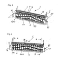
- Fig. 1 shows a receiving device 1, which is provided for attachment to a harvester, not shown. It consists essentially of a occupied with receiving prongs 20 drum 2, in the side panels 9 and 10, which are connected to the harvesting vehicle, is stored.
- a scraper comb 28 establishes a rigid connection between the side members 9 and 10.
- the stripping comb 28 is in the illustrated embodiment with long strippers 30 and short scrapers 31 occupied.
- the scrapers 30 and 31 are provided at their front edge in each case with a cutting edge (see FIG. Fig. 11 ).
- the assembly of the drum 2 is carried out by sliding the segments 3 on the central tube 7, wherein the components are preferably welded together.
- the spiral arrangement of the tine holder 5 It is preferred that the spiral arrangement of the tine holder 5. It is produced such that when lining up the segments 3 during assembly of the drum 2, z. B. a spacer 11 is mounted in the middle of the hole pattern 36 of a flange 55 and engages the flange 55 of the subsequent segment 3 in an outer hole 37 of the hole pattern 36.
- the pitch direction of the helical arrangement of the tine holders 5, is determined by whether the spacer 11, which is mounted in a flange 55 in the middle of the hole pattern 36, the flange 55 of the adjacent segment 3, seen in the direction of rotation, received in a front or rear hole 37 becomes.
- the gap 18 generated by the spacers 11 between the segments 3 serves to receive the rings 58, and the ring pieces 59.
- the rings 58 are partially inserted between the flanges 55 of adjacent segments 3 and welded thereto. Since the inner diameter of the rings 58 is smaller than the outer diameter of the flanges 55, rings 58 and segments 3 must be alternately plugged onto the central tube 7 during assembly.
- rings 58 forming ring pieces 59 can also be used as an alternative to complete rings 58. It is advantageous that the ring pieces 59 can also be subsequently inserted into the gaps 18 between the segments 3.
- the ring pieces 59 are fastened by means of the holes 39 of the hole pattern 38 by screw. But you can also be attached differently, for example, welded, be.
- receiving tines 20 are inserted into the pockets formed by the tine holders 5.
- These include a base 21, from the top 26 two Legs 22 protrude. In the middle of the base 21, a mounting hole 23 is arranged with countersink 41. This receives a screw 24, which by means of a weld nut 27, which is arranged centrally on the underside of the tine holder 5, the receiving prongs 20.
- the receiving prongs 20 are made in the illustrated embodiment of a plastic, or a plastic alloy.
- a metal bushing 25 dresses the mounting hole 23 in the base 21, it is slightly shorter than the distance between the support surface of the base 21 in the tine holder 5 and the bearing surface of the head of the screw 24 and generated when tightening the screw 24 initially a bias in the base 21 and then a firm seat of the same.
- the long scrapers 30 each extend from a trailing edge 33 to the cylinder jacket 8, where a front edge 32 of the scraper 30 rests almost on the cylinder jacket 8. It remains between the front edge 32 and the cylinder jacket 8, a gap x, which allows a smooth rotation of the drum 2.
- the short scrapers 31 also include a trailing edge 33 from which they extend to a leading edge 32.
- the leading edges 32 may be formed in various embodiments.
- the design of a first embodiment of the leading edges 32 is in particular the FIGS. 8a and 8b refer to.
- the short scrapers 31 have at their front edge 32 a profile 52 which engages over the ring 58, or the ring 58 formed from ring pieces 59, without contact.
- the front edge 32 is pointed toward the drum casing surface, and in each case has a trapezoidal contour with two cutting edges 49, so that the picked crop is under attack, cut if necessary, and passed on in a low-resistance manner.
- the harvested by the legs 22 of the receiving prongs 20 crop is raised by means of the scrapers 30 and 31 and forwarded to a downstream pressing and / or cutting device.
- the legs 22 of the receiving prongs 20 are conical and run between the scrapers 30 and 31 in the columns 44 a. As the drum 2 continues to rotate, the legs 22 sink in the gaps 44.
- the conicity of the scrapers 30 thus compensates for the conicity of the legs 22 of the receiving prongs 20, so that the distances - and thus the gap 44 - between leg 22 and matched strippers 30 and 31 are kept approximately constant.
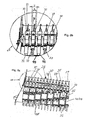
- Fig. 9a shows two segments 3 of an alternative embodiment.
- the long scrapers 30 are chamfered obliquely at their front edge 32 and lie with their lower edge almost on the cylinder jacket 8.
- Each segment 3 comprises tine pockets 5, into each of which a receiving tine 20 comprising a base 21 and two legs 22 is inserted.
- the receiving prongs 20 may be designed so that a preferably U-shaped guide track 19 is formed between the legs 22 (see FIG. Fig. 9e ). Between radially adjacent receiving prongs 20 ring pieces 17 are arranged, which continue the U-shaped guideway 19. In use, the drum 2 thus rotates under the long scrapers 30 through an overall U-shaped guideway.
- the short scrapers 31 are each arranged in the region of the flange locations of two adjacent segments 3.
- the segments 3 may be designed differently with respect to their flanges 55.
- the 10a, 10b and 10c show three differently shaped rings 56 ', 56 "and 56"'.
- the rings 56 ', 56 "and 56'” are either made directly from the flanges 55 by means of suitable manufacturing processes, or additional parts are formed by the flanges 55.
- the spacers 11 already described above are arranged.
- beads 57 disposed on the outer circumference of the flanges 55 replace the rings (58) described above.
- the segments 3 are placed against each other.
- the mirror-image arranged, mutually opposed beads 57 each form a ring 56 with circumferential groove 54.
- Crop material, which catches in the labor input at the front edge 32 of a scraper 30 is sheared off during rotation of the drum 2 between the cutting edge 49 and counter-blade 50.
Landscapes
- Life Sciences & Earth Sciences (AREA)
- Environmental Sciences (AREA)
- Outside Dividers And Delivering Mechanisms For Harvesters (AREA)
Applications Claiming Priority (1)
| Application Number | Priority Date | Filing Date | Title |
|---|---|---|---|
| DE102014117740.1A DE102014117740B4 (de) | 2014-12-03 | 2014-12-03 | Aufnahmevorrichtung an einer Erntemaschine |
Publications (1)
| Publication Number | Publication Date |
|---|---|
| EP3028558A1 true EP3028558A1 (fr) | 2016-06-08 |
Family
ID=54780177
Family Applications (1)
| Application Number | Title | Priority Date | Filing Date |
|---|---|---|---|
| EP15197665.1A Withdrawn EP3028558A1 (fr) | 2014-12-03 | 2015-12-02 | Dispositif de ramassage d'une machine de récolte |
Country Status (2)
| Country | Link |
|---|---|
| EP (1) | EP3028558A1 (fr) |
| DE (1) | DE102014117740B4 (fr) |
Cited By (5)
| Publication number | Priority date | Publication date | Assignee | Title |
|---|---|---|---|---|
| WO2017140797A1 (fr) * | 2016-02-19 | 2017-08-24 | B. Strautmann & Söhne GmbH u. Co. KG | Ramasseur équipé d'anneaux dentés et de segments formant dents |
| CN109562415A (zh) * | 2016-11-29 | 2019-04-02 | 布勒股份公司 | 松散材料的清洁 |
| CN110122048A (zh) * | 2019-06-25 | 2019-08-16 | 安徽科技学院 | 一种方便压料的新型农作物秸秆粉碎覆盖还田机 |
| EP3552470A1 (fr) * | 2018-04-11 | 2019-10-16 | KLP Baumaschinen GmbH | Cadre pour un dispositif de réception et de transport, de préférence de produit à faucher ou à tondre |
| EP4118949A1 (fr) * | 2021-07-13 | 2023-01-18 | B. Strautmann & Söhne GmbH u. Co. KG | Dispositif de ramassage pour une moissoneuse |
Families Citing this family (7)
| Publication number | Priority date | Publication date | Assignee | Title |
|---|---|---|---|---|
| DE102018121277A1 (de) * | 2018-08-31 | 2020-03-05 | B. Strautmann & Söhne GmbH u. Co. KG | Aufnahmevorrichtung für eine Erntemaschine mit einem durch eine Räumvorrichtung ausgebildeten Wickelschutz |
| DE102020008089B4 (de) | 2020-03-19 | 2024-09-26 | Ludwig Bergmann Gmbh | Aufnahmevorrichtung an einer Erntemaschine |
| DE102020001828B4 (de) | 2020-03-19 | 2021-11-04 | Richard Kleine-Nieße | Aufnahmevorrichtung an einer Erntemaschine |
| EP3888446B1 (fr) | 2020-03-19 | 2023-09-27 | Ludwig Bergmann GmbH | Dispositif de réception d'une moissonneuse |
| DE102020117032A1 (de) | 2020-06-29 | 2021-12-30 | B. Strautmann & Söhne GmbH u. Co. KG | Aufnahmevorrichtung mit auf einer Trommel befestigten Förderzinken |
| DE102020117038A1 (de) | 2020-06-29 | 2021-12-30 | B. Strautmann & Söhne GmbH u. Co. KG | Trommel für eine Aufnahmevorrichtung |
| US12593754B2 (en) | 2022-05-11 | 2026-04-07 | Vermeer Manufacturing Company | Round baler crop pickups |
Citations (4)
| Publication number | Priority date | Publication date | Assignee | Title |
|---|---|---|---|---|
| EP0903077A1 (fr) * | 1997-09-15 | 1999-03-24 | Alois Freitag | Ramasseur por recoltes |
| US20130167499A1 (en) | 2011-12-28 | 2013-07-04 | Agco Corporation | Tine pickup with narrow tine spacing for a baler |
| EP2724607A1 (fr) * | 2012-10-26 | 2014-04-30 | D.B.D. S.r.l. | Machine pour la collecte de boutures de plante |
| EP2845463A1 (fr) * | 2013-09-05 | 2015-03-11 | B. Strautmann & Söhne GmbH & Co. KG | Dispositif de ramassage pour moissonneuses |
Family Cites Families (3)
| Publication number | Priority date | Publication date | Assignee | Title |
|---|---|---|---|---|
| DE102006061010B4 (de) * | 2006-12-22 | 2014-08-07 | Alois Pöttinger Maschinenfabrik Gmbh | Erntemaschine |
| DE102012108708B4 (de) * | 2012-09-17 | 2015-02-05 | Thomas Reiter | Erntegutaufnehmer |
| DE102013105197B3 (de) * | 2013-05-22 | 2014-09-11 | B. Strautmann & Söhne GmbH u. Co. KG | Aufnahmevorrichtung an Erntemaschinen mit Stützelementen für die Aufnahmezinken |
-
2014
- 2014-12-03 DE DE102014117740.1A patent/DE102014117740B4/de not_active Expired - Fee Related
-
2015
- 2015-12-02 EP EP15197665.1A patent/EP3028558A1/fr not_active Withdrawn
Patent Citations (5)
| Publication number | Priority date | Publication date | Assignee | Title |
|---|---|---|---|---|
| EP0903077A1 (fr) * | 1997-09-15 | 1999-03-24 | Alois Freitag | Ramasseur por recoltes |
| DE19740589A1 (de) | 1997-09-15 | 1999-03-25 | Hermann Lohmann Maschinenfabri | Aufnahmeeinheit für Erntegut |
| US20130167499A1 (en) | 2011-12-28 | 2013-07-04 | Agco Corporation | Tine pickup with narrow tine spacing for a baler |
| EP2724607A1 (fr) * | 2012-10-26 | 2014-04-30 | D.B.D. S.r.l. | Machine pour la collecte de boutures de plante |
| EP2845463A1 (fr) * | 2013-09-05 | 2015-03-11 | B. Strautmann & Söhne GmbH & Co. KG | Dispositif de ramassage pour moissonneuses |
Cited By (7)
| Publication number | Priority date | Publication date | Assignee | Title |
|---|---|---|---|---|
| WO2017140797A1 (fr) * | 2016-02-19 | 2017-08-24 | B. Strautmann & Söhne GmbH u. Co. KG | Ramasseur équipé d'anneaux dentés et de segments formant dents |
| EP3864953A1 (fr) * | 2016-02-19 | 2021-08-18 | B. Strautmann & Söhne GmbH u. Co. KG | Entraînement pourvu d'anneaux dentés et de segments dentés |
| US11470782B2 (en) | 2016-02-19 | 2022-10-18 | B. Strautmann & Söhne GmbH u. Co. KG | Pick-up having tine rings and tine segments |
| CN109562415A (zh) * | 2016-11-29 | 2019-04-02 | 布勒股份公司 | 松散材料的清洁 |
| EP3552470A1 (fr) * | 2018-04-11 | 2019-10-16 | KLP Baumaschinen GmbH | Cadre pour un dispositif de réception et de transport, de préférence de produit à faucher ou à tondre |
| CN110122048A (zh) * | 2019-06-25 | 2019-08-16 | 安徽科技学院 | 一种方便压料的新型农作物秸秆粉碎覆盖还田机 |
| EP4118949A1 (fr) * | 2021-07-13 | 2023-01-18 | B. Strautmann & Söhne GmbH u. Co. KG | Dispositif de ramassage pour une moissoneuse |
Also Published As
| Publication number | Publication date |
|---|---|
| DE102014117740A1 (de) | 2016-06-09 |
| DE102014117740B4 (de) | 2020-11-05 |
Similar Documents
| Publication | Publication Date | Title |
|---|---|---|
| EP3028558A1 (fr) | Dispositif de ramassage d'une machine de récolte | |
| EP2842412B1 (fr) | Élément de traitement de récoles et/ou de transport pour une ramasseuse-hacheuse | |
| EP3416473B1 (fr) | Dispositif de reception de recolte | |
| EP3007540B1 (fr) | Dispositif à cueillir | |
| EP1980144A1 (fr) | Moissonneuse agricole | |
| EP3028559A1 (fr) | Pick-up d'une moissonneuse | |
| EP4118949B1 (fr) | Dispositif de ramassage pour une moissoneuse | |
| EP2481277A1 (fr) | Mécanisme de battage d'une moissonneuse-batteuse | |
| DE102013211829A1 (de) | Element zum Abstützen und/oder Leiten von Erntegut in einer Erntemaschine | |
| EP1306003B1 (fr) | Presse-botteleuse pour des produits agricoles | |
| EP3238526B1 (fr) | Moissonneuse comprenant un ramasseur | |
| DE102018121273A1 (de) | Aufnahmevorrichtung für eine Erntemaschine mit Stützelementen für die Abstreifer der Aufnahmevorrichtung | |
| EP1040746A1 (fr) | Appareil pour récolter les fruits sur pied | |
| DE102014117742B3 (de) | Aufnahmevorrichtung an einer Erntemaschine | |
| DE102006061010B4 (de) | Erntemaschine | |
| DE202010010077U1 (de) | Gutaufnehmer | |
| EP3932176B1 (fr) | Tambour pour un dispositif de réception | |
| EP3593623A1 (fr) | Machine de récolte doté d'un dispositif de ramassage de récolte | |
| DE202009003598U1 (de) | Erntemaschine | |
| EP3689130A1 (fr) | Enveloppe de rouleau pour un rouleau de conditionnement | |
| EP3888446B1 (fr) | Dispositif de réception d'une moissonneuse | |
| DE102018121277A1 (de) | Aufnahmevorrichtung für eine Erntemaschine mit einem durch eine Räumvorrichtung ausgebildeten Wickelschutz | |
| DE102021102161A1 (de) | Aufnahmevorrichtung | |
| EP3315013B1 (fr) | Moissonneuse | |
| DE102016108191A1 (de) | Erntemaschine mit einer Erntegutaufnahmevorrichtung |
Legal Events
| Date | Code | Title | Description |
|---|---|---|---|
| PUAI | Public reference made under article 153(3) epc to a published international application that has entered the european phase |
Free format text: ORIGINAL CODE: 0009012 |
|
| AK | Designated contracting states |
Kind code of ref document: A1 Designated state(s): AL AT BE BG CH CY CZ DE DK EE ES FI FR GB GR HR HU IE IS IT LI LT LU LV MC MK MT NL NO PL PT RO RS SE SI SK SM TR |
|
| AX | Request for extension of the european patent |
Extension state: BA ME |
|
| STAA | Information on the status of an ep patent application or granted ep patent |
Free format text: STATUS: THE APPLICATION IS DEEMED TO BE WITHDRAWN |
|
| 18D | Application deemed to be withdrawn |
Effective date: 20161209 |