EP3028603B1 - Bettgestell - Google Patents
Bettgestell Download PDFInfo
- Publication number
- EP3028603B1 EP3028603B1 EP14196039.3A EP14196039A EP3028603B1 EP 3028603 B1 EP3028603 B1 EP 3028603B1 EP 14196039 A EP14196039 A EP 14196039A EP 3028603 B1 EP3028603 B1 EP 3028603B1
- Authority
- EP
- European Patent Office
- Prior art keywords
- supporting elements
- mattress supporting
- mattress
- frame
- inclination
- Prior art date
- Legal status (The legal status is an assumption and is not a legal conclusion. Google has not performed a legal analysis and makes no representation as to the accuracy of the status listed.)
- Active
Links
Images


Classifications
-
- A—HUMAN NECESSITIES
- A47—FURNITURE; DOMESTIC ARTICLES OR APPLIANCES; COFFEE MILLS; SPICE MILLS; SUCTION CLEANERS IN GENERAL
- A47C—CHAIRS; SOFAS; BEDS
- A47C20/00—Head-, foot- or like rests for beds, sofas or the like
- A47C20/04—Head-, foot- or like rests for beds, sofas or the like with adjustable inclination
-
- A—HUMAN NECESSITIES
- A47—FURNITURE; DOMESTIC ARTICLES OR APPLIANCES; COFFEE MILLS; SPICE MILLS; SUCTION CLEANERS IN GENERAL
- A47C—CHAIRS; SOFAS; BEDS
- A47C20/00—Head-, foot- or like rests for beds, sofas or the like
- A47C20/08—Head-, foot- or like rests for beds, sofas or the like with means for adjusting two or more rests simultaneously
Definitions
- the present inventive concept relates to a base for a bed, the base comprising a frame and a mattess support.
- beds may be provided with an adjustment function allowing the inclination of a back and head section of the bed to be varied, typically between a horizontal orientation and an upright orientation.
- the adjustable portion of the bed may thereby act as a back- and head-rest for a user, for example, half-lying or sitting in the bed.
- US4674140 discloses an articulated bedspring and mattress for use with such articulated bedspring.
- An objective of the present inventive concept is to address this issue of such prior art beds.
- a base for a bed comprising a frame and a mattress support extending along a longitudinal direction of the frame and including:
- a longitudinal position of the first set of mattress supporting elements and a longitudinal position of the third set of mattress supporting elements may change while the inclination of the first set of mattress supporting elements is increased.
- the longitudinal position of the first set of mattress supporting elements and the longitudinal position of the third set of mattress supporting elements may be dependent on, or a function of, an angle of the inclination of the third set of mattress supporting elements.
- Arranging the first set of mattress supporting elements to move such that the mattress supporting element of the first set of mattress supporting elements which is closest to the third set of the mattress supporting elements (hereinafter also referred to as "said mattress supporting element of the first set of mattress supporting elements") becomes increasingly separated from the second set of mattress supporting elements enables mattress overflow, which otherwise could occur, to be limited or even eliminated.
- the movement of the third set of mattress supporting elements allows for a gradual compensation for the local reduction of mattress support between the first set of mattress supporting elements and the second set of mattress supporting elements, which is a consequence of the increasing separation between said mattress supporting element of the first set of mattress supporting elements and the second set of mattress supporting elements.
- the inventive base enables an adequate mattress support to be maintained even for a relatively great displacement of the first set of mattress supporting elements (i.e. a relatively wide gap between the mattress supporting element of the first set of mattress supporting elements which is closest to the third set of mattress supporting elements and the second set of mattress supporting elements).
- the position of this gap may for example correspond to the mid- or hip portion of a user of the bed. Consequently, the first set of mattress supporting elements may be displaced along the longitudinal direction of the frame to such an extent that mattress overflow is eliminated or at least reduced while maintaining support for the mid- or hip portion of the user.
- the longitudinal direction of the frame may be defined as a direction from a foot end of the frame towards a head end of the frame.
- the first set of mattress supporting elements may be arranged to move towards the head end of the frame while the inclination of the first set of mattress supporting elements is increased.
- the third set of mattress supporting elements may be arranged to move towards the head end of the frame while the inclination of the first set of mattress supporting elements is increased.
- the first set of mattress supporting elements may be arranged at a longitudinal position along the frame corresponding to an upper section of the mattress support.
- the upper section may also be referred to as a back and head section of the mattress support.
- the second set of mattress supporting elements may be arranged at a longitudinal position along the frame corresponding to a lower section of the mattress support.
- the lower section may also be referred to as a leg section of the mattress support.
- the third set of mattress supporting elements may be arranged at a longitudinal position along the frame corresponding to a mid section of the mattress support.
- the mid section may also be referred to as a hip or section of the mattress support.
- Each of the first, second and third set of mattress supporting elements includes one or more supporting elements, each supporting element presenting a mattress supporting surface for bearing against an underside of a mattress.
- a supporting element may extend in a direction transverse to the longitudinal direction of the frame.
- a supporting element may extend between mutually opposite long sides of the frame.
- first set of mattress supporting elements being pivotable in relation to the frame, an inclination of the first set of mattress supporting elements with respect to the second set of mattress supporting elements may be adjusted.
- the inclination of the first set of mattress supporting elements may be adjustable through an adjustment range, wherein a first end point of the adjustment range corresponds to a lowered orientation to and a second end point of the adjustment range corresponds to a raised orientation.
- the lowered orientation may correspond to a horizontal, or substantially horizontal, orientation.
- the raised orientation may correspond to a sitting or upright orientation.
- the third set of mattress supporting elements is arranged to continuously support a mattress, throughout the inclination adjustment range (e.g. extending from the above-mentioned the first end point to the above-mentioned second end point) of the first set of mattress supporting elements.
- the third set of mattress supporting elements may have a corresponding function as the other mattress supporting elements. This also enables a rational production process since existing bases with an adjustment function may be provided with set of movable mattress supporting elements.
- the movement of the first set of mattress supporting elements along the longitudinal direction may be mechanically coupled to the adjustment of the inclination of the first set of mattress supporting elements. Thereby, no separate driving means for the movement of the first set of mattress supporting elements is required. Instead the movement may be driven by a same driving means as used for driving the adjustment of the inclination.
- the movement of the third set of mattress supporting elements is mechanically coupled to the adjustment of the inclination of the first set of mattress supporting elements. Thereby, no separate driving means for the movement of the third set of mattress supporting elements is required. Instead the movement of the third set of mattress supporting elements may be driven by a same driving means as used for driving the adjustment of the inclination.
- the movement of the third set of mattress supporting elements may be mechanically coupled to the adjustment of the inclination of the first set of mattress supporting elements by a direct coupling between the movement of the third set of mattress supporting elements and a mechanism for adjusting the inclination of the first set of mattress supporting elements.
- the movement of the third set of mattress supporting elements may be mechanically coupled to the adjustment of the inclination of the first set of mattress supporting elements via the movement of the first set of mattress supporting elements.
- the movement of the third set of mattress supporting elements is mechanically coupled to the adjustment of the inclination of the first set of mattress supporting elements such that, while the inclination of the first set of mattress supporting elements falls below a predetermined threshold angle, a longitudinal position of the third set of mattress supporting elements is fixed while the inclination of the first set of mattress supporting elements is increased, and while the inclination of the first set of mattress supporting elements exceeds the predetermined threshold angle, the third set of mattress supporting elements moves along the longitudinal direction while the inclination of the first set of mattress supporting elements is increased.
- the position of the third set of mattress supporting elements may be fixed during an initial raising of the first set of mattress supporting elements and, as the separation between the mattress supporting element of the first set of mattress supporting elements which is closest to the third set of mattress supporting elements and the second set of mattress supporting elements exceeds a predetermined limit, the third set of mattress supporting elements may begin to move along frame.
- the base comprises a coupling element arranged to pull the third set of mattress supporting elements along the frame while the inclination of the first set of mattress supporting elements is increased.
- the coupling element may pull the third set of mattress supporting elements towards a head end of the frame while the inclination of the first set of mattress supporting element is increased.
- the coupling element may be arranged to push the third set of mattress supporting elements towards a foot end of the frame while the inclination of the first set of mattress supporting elements is decreased.
- the base may further comprise a support member which is arranged on the frame and movable along the longitudinal direction, wherein the third set of mattress supporting elements is carried by the support member, and wherein the coupling element is connected to the support member and arranged to pull the support member along the frame while the inclination of the first set of mattress supporting elements is increased. Thereby, the coupling element may pull the third set of mattress supporting elements along the frame.
- the coupling element may be pivotally connected to the support member.
- the coupling element may further be pivotally connected to a pivoting member which is arranged to pivot when the first set of mattress supporting elements pivots and pull the coupling element along the longitudinal direction.
- a rate of movement of the third set of mattress supporting elements in relation to the frame may be less than a rate of movement of the first set of mattress supporting elements in relation to the frame. Thereby the third set of mattress supporting elements may lag behind the movement of the first set of mattress supporting elements.
- the third set of mattress supporting elements may be arranged to trace a straight path while the inclination of the first set of mattress supporting elements is increased, the straight path having a main component which is parallel to the longitudinal direction of the frame.
- the straight path may be parallel to a plane in which the third set of mattress supporting elements supports the mattress.
- the third set of mattress supporting elements may support the mattress in a same plane while the inclination of the first set of mattress supporting elements is varied.
- the straight path may be parallel to a horizontal plane.
- the base may comprise guide means provided along a side support structure of the frame and arranged to guide a movement of the third set of mattress supporting elements along the side support structure.
- the guide means may be arranged to guide the movement along the above-mentioned straight path.
- the guide means may include a guide track, a guide rail or a guide groove.
- the base may further comprise a support member which engages with the guide means and is movable along the guide means, and wherein the third set of mattress supporting elements is carried by the support member.
- the third set of mattress supporting elements may thus be moved along the longitudinal direction by causing the support member to move.
- the base comprises a pivotable support structure arranged to support the first set of mattress supporting elements and being pivotally connected to a side support structure of the frame, wherein a pivot connection between the pivotable support structure and the side support structure of the frame is arranged to move along the longitudinal direction of the frame while the inclination of the first set of mattress supporting elements is increased.
- a separation, along the longitudinal direction, between the pivot connection and the second set of mattress supporting elements may increase. This provides a reliable and simple mechanism for coupling an adjustment of the inclination of the first set of mattress supporting elements to the movement of the first set of mattress supporting elements along the longitudinal direction.
- the pivotable support structure may include a set of arms, for example a pair of arms arranged on opposite side support structures of the frame.
- the base may further comprise guide means provided along a side support structure of the frame and arranged to guide a movement of the pivot connection between the pivotable support structure and the side support structure along the guide means.
- the guide means for the pivot connection may be the same as the guide means for the third set of mattress supporting elements, or a separate guide means.
- the guide means may include a guide track, a guide rail or a guide groove.
- the pivot connection between the pivotable support structure and the side support structure may be arranged to trace a straight path while the inclination of the first set of mattress supporting elements is increased, the straight path having a main component which is parallel to the longitudinal direction of the frame.
- the straight path may be parallel to a plane in which the third set of mattress supporting elements supports the mattress.
- the straight path may be parallel to a horizontal plane.
- the base may further comprise a coupling member which is pivotally connected to the frame and to the pivotable support structure and arranged to cause the pivot connection between the pivotable support structure and the side support structure to move along the longitudinal direction when the inclination of the pivotable support structure is increased.
- the coupling member may be arranged to transfer a torque acting on the pivotable support structure to a force causing the pivot connection to move along the longitudinal direction. This provides a reliable and relatively inexpensive means for causing the pivot connection to move when the inclination of the first set of mattress supporting elements is adjusted.
- the base comprises a pivotable support structure arranged to support the first set of mattress supporting elements and the base further comprising a pair of angled links which are pivotally connected to a side support structure of the frame and to the pivotable support structure, wherein the pair of links are arranged to cooperate to allow the pivotable support structure to pivot in relation to the frame and simultaneously move along the longitudinal direction while the inclination of the first set of mattress supporting elements is increased.
- the pivotable support structure may include a set of arms, for example a pair of arms arranged on opposite side support structures of the frame.
- the links of the pair may be pivotally connected to the side support structure at two different positions.
- the links of the pair may be pivotally connected to the pivotable support structure at two different positions.
- a position of at least the mattress supporting element of the second set of mattress supporting elements which is closest to the third set of mattress supporting elements may be fixed in relation to the frame, i.e. while the inclination of the first set of slats is increased.
- the second set of mattress supporting elements may be arranged to be stationary in relation to the frame while the inclination of the first set of mattress supporting elements is increased.
- an inclination of at least a subset of the second set of mattress supporting elements is adjustable in relation to the third set of slats and/or the frame.
- the subset of mattress supporting elements may correspond to a lower or leg section of the mattress support.
- a leg section of the mattress support may be adjustable.
- the lower section is adjustable independently from the mid and upper section of the mattress support (i.e. the first and third set of mattress supporting elements).
- the longitudinal position of a pivot axis for said subset is fixed in relation to the frame.
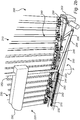
- Figs 1a-c illustrate a base 100 for a bed.
- the base 100 includes a frame 102 and a mattress support 104 for supporting a mattress, which has been omitted from the drawings to improve the intelligibility thereof.
- the frame 102 and the mattress support 104 may generally be dimensioned to support a single bed mattress, or even two bed mattresses placed side by side.
- the frame 102 which also may be referred to as a framework, acts as a support structure for the mattress support 104 and includes two side support structures extending along the long sides of the base 100, and optionally a head end support structure and a foot end support structure extending along the short sides of the base 100.
- the main load bearing parts of the frame 102 may typically be made of wood and/or metal, however composite materials is also possible.
- the base 100 may further be provided with legs, a head board and/or a foot board. These optional elements may be connected to the frame 102 e.g. by screwing, bolting or the like.
- the mattress support 104 extends along the frame 102, along a direction defined from the foot end to the head end of the base 100 or, correspondingly, from the foot end to the head end of the frame 102.
- the foot-head direction may in the following also be referred to as a longitudinal direction of the base 100 or the frame 102.
- the mattress support 104 includes a first set of mattress supporting elements 110, a second set of mattress supporting elements 120 and a third set of mattress supporting elements 130.
- Each set of mattress supporting elements 110, 120, 130 comprises a number of mattress supporting elements.
- the particular number of mattress supporting elements of each set 110, 120, 130 shown in Figs 1a-c only constitutes one example and both greater or lower numbers of mattress supporting elements are possible.
- the mattress supporting elements of the sets of mattress supporting elements 110, 120, 130 may typically be made of wood and/or metal, however composite materials is also possible.
- the sets of mattress supporting elements 110, 120, 130 are distributed along the longitudinal direction of the frame 102.
- the first set of mattress supporting elements 110 is arranged to support a back and head section of the mattress (or analogously, a back and head portion of a user of the bed).
- the second set of mattress supporting elements 120 is arranged to support a leg section of the mattress (or analogously, a leg portion of a user of the bed).
- the third set of mattress supporting elements 130 is arranged to support a mid or hip section of the mattress (or analogously, a mid or hip portion of a user of the bed).
- the mattress supporting elements of the sets 110, 120, 130 extend in parallel to each other and in a direction transverse to the longitudinal direction of the frame 102.
- Each mattress supporting element is carried at its respective ends by the mutually opposite long sides (i.e. the side support structures) of the frame 102.
- Each mattress supporting element presents a surface for bearing against an underside of a mattress.
- each mattress supporting element may be formed as a slat and present a continuous mattress supporting surface extending between its opposite ends.
- a mattress supporting element may alternatively present two or more discrete mattress supporting surfaces, distributed transverse to the longitudinal direction of the frame 102.
- the discrete surfaces may for example be provided by a row of separate units (e.g.
- each one of the sets of mattress supporting elements 110, 120, 130 may include a combination of mattress supporting elements of the above-described types (e.g. a combination of one or more slats and one or more rows of panels or pads).
- the first set of mattress supporting elements 110 is pivotable in relation to the frame 102. Thereby, an inclination of the first set of mattress supporting elements 110 with respect to the second set of mattress supporting elements 120 and the third set of mattress supporting elements 130 is adjustable.
- "an inclination" of the first set of mattress supporting elements 110 may be understood as an inclination with respect to a horizontal plane.
- the inclination of the first set of mattress supporting elements 110 is adjustable throughout an adjustment range extending from, what may be referred to as, a lowered orientation to, what may be referred to as, a raised orientation.
- the lowered orientation may, in use of the base 100, correspond to a horizontal, or substantially horizontal, orientation.
- the orientation in Fig. 1a may correspond to a lying position for a user
- the orientation in Fig. 1c may correspond to a sitting or upright orientation for the user.
- Fig. 1b may correspond to an orientation intermediate the orientations in Figs 1a and 1c .
- the base 100 comprises a support structure 140 carrying or supporting the first set of mattress supporting elements 110.
- the support structure 140 is pivotally connected to the side support structure of the frame 102 and will therefore in the following be referred to as the pivotable support structure 140.
- the pivotable support structure 140 may include a pair of arms however it may also be designed as a lattice of arms or beams, or as a stiff panel pivotally connected to the side support structures of the frame 102 and coextensive with the longitudinal and width dimension of the first set of mattress supporting elements 110 and carrying the first set of mattress supporting elements 110.
- the inclination of the first set of mattress supporting elements 110 may be controlled by electrical means, such as an electric motor or an hydraulically or pneumatically controlled piston acting (e.g. by pushing) on the pivotable support structure 140.
- electrical means such as an electric motor or an hydraulically or pneumatically controlled piston acting (e.g. by pushing) on the pivotable support structure 140.
- a user may for example increase or reduce the inclination by pressing an appropriate button on a remote control or the like.
- the first set of mattress supporting elements 110 is arranged to move, i.e. be displaced, along the longitudinal direction such that a separation between the mattress supporting element of the first set of mattress supporting elements 110, which is closest to the third set of mattress supporting elements 130, and the second set of mattress supporting elements 120 is increased while the inclination of the first set of mattress supporting elements 110 is increased.
- the greater an inclination of the first set of mattress supporting elements 110 the greater a separation (along the longitudinal direction of the frame 102), between said mattress supporting element of the first set of mattress supporting elements 110 and the second set of mattress supporting elements 120 will be.
- a width i.e.
- the movement of the first set of mattress supporting elements 110 may be mechanically coupled to the adjustment of the inclination of the first set of mattress supporting elements 110.
- Figs 1c also the third set of mattress supporting elements 130 is arranged to be moved or displaced along the longitudinal direction of the frame 102 while the inclination of the first set of mattress supporting elements 110 is increased. Accordingly, Figs 1a-c show the third set of mattress supporting elements 130 at different longitudinal positions along the frame 102.
- the movement of the third set of mattress supporting elements 130 along the longitudinal direction of the frame 102 is such that, the greater an inclination of the first set of mattress supporting elements 110, the greater a separation D1 (along the longitudinal direction of the frame 102) between the mattress supporting element of the first set of mattress supporting elements 110, which is closest to the third set of mattress supporting elements 130, and the third set of mattress supporting elements130, and also a separation D2 (along the longitudinal direction of the frame 102) between the third set of mattress supporting elements 130 and the second set of mattress supporting elements 120, will be.
- D1 may be referred to as a longitudinally extending gap between the first set of mattress supporting elements 110 and the third set of mattress supporting elements 130.
- the third set of mattress supporting elements 130 may continuously support the mattress within the gap of increasing width between the first set of mattress supporting elements 110 and the second set of mattress supporting elements 120, throughout the inclination adjustment range of the first set of mattress supporting elements 110.
- the movement of the third set of mattress supporting elements 130 partitions the gap between the first set of mattress supporting elements 110 and the second set of mattress supporting elements 120 into the two sub-gaps D1 and D2, on opposite sides of the third set of mattress supporting elements 130.
- the separation D1 may be equal to the separation D2, at least through a sub range of the inclination adjustment range of the first set of mattress supporting elements 110, but optionally throughout the inclination adjustment range thereof.
- the movement or displacement of the third set of mattress supporting elements 130 may be mechanically coupled to the adjustment of the inclination of the first set of mattress supporting elements 110.
- a user may gradually increase the inclination of the first set of mattress supporting elements 110 from a horizontal orientation. As the inclination is increased the separation D1 will increase. Simultaneously, albeit at a lower longitudinal movement rate than the first set of mattress supporting elements 110, the third set of mattress supporting elements 130 will move towards the head end of the frame 102, thereby resulting in an increased separation D2. Hence, the third set of mattress supporting elements 130 may, in a lagging manner, follow the longitudinal movement of the first set of mattress supporting elements 110.
- the third set of mattress supporting elements 130 may thus, at least partially, compensate for a local reduction of support for the mattress, caused by the increased separation between the mattress supporting element of the first set of mattress supporting elements 110, which is closest to the third set of mattress supporting elements 130, and the second set of mattress supporting elements 120.
- the second set of mattress supporting elements 120 remains stationary, i.e. in a same position, in relation to the frame 102.
- an inclination and/or a level of at least a subset of the second set of mattress supporting elements 120 may be adjustable in relation to the frame 102.
- a subset of mattress supporting elements corresponding to a leg section of the mattress support may be adjustable.
- the subset of the second set of mattress supporting elements 120 is preferably adjustable independently from the first and third set of mattress supporting elements 110, 130.
- Various mechanisms for providing such an adjustment are known in the art as such and will therefore not be discussed in further detail herein.
- the adjustment of the leg section may be controlled by the same electrical means as those discussed above for controlling the inclination of the first set of mattress supporting elements 110.
- the longitudinal position of at least a pivot axis of the subset of the second set of mattress supporting elements 120, or the longitudinal position of at least the mattress supporting element of the second set of mattress supporting elements 120 which is closest to the third set of mattress supporting elements 130 is fixed in relation to the frame 102, while the inclination of the first set of mattress supporting elements 110 is varied.
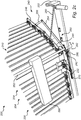
- Figs 2a-c illustrate a portion of a base 200 for a bed.
- the base 200 includes elements generally corresponding to the base 100. More specifically, the base 200 includes a frame 202 and a mattress support 204 generally corresponding to the frame 102 and the mattress support 104 illustrated in Figs 1a-c .
- Fig. 3 illustrate a cross section of the base 200, extending parallel to the longitudinal direction of the base 200 and the frame 202. The illustrated views show only one side of the frame 202.
- the frame 202 however further comprises a second not shown side, arranged directly opposite to the first side. In particular, the second side may be mirrored with respect to the first side portion along the longitudinal direction of the base 200.
- the illustrated side of the frame 202 the description applies correspondingly to the opposite side of the frame 202.
- the mattress support 204 includes a first set of mattress supporting elements 210, corresponding to the first set of mattress supporting elements 110, a second set of mattress supporting elements 220, corresponding to the second set of mattress supporting elements 120 and a third set of mattress supporting elements 230, corresponding to the third set of mattress supporting elements 130.
- the mattress supporting elements of the sets 210, 220, 230 may be connected to the frame 102 by respective springs 206 in a pair-wise manner. This is however optional and other manners of connecting mattress supporting elements to a frame are well-known in the art.
- the base 200 further includes a pivotable support structure 240 supporting the first set of mattress supporting elements 210.
- the pivotable support structure 240 corresponds to the pivotable support structure 140.
- the support structure 240 includes a first arm 244 supporting a first subset of the first set of mattress supporting elements 210.
- the pivotable support structure 240 is connected to the frame 202 by a pivot connection 242.
- the pivot connection 242 is arranged to move along the frame 202 while the inclination of the pivotable support structure 240 is varied.
- the frame 202 is provided with a guide means 270 including a guide track.
- the guide means 270 is arranged on an inwardly facing surface of the frame 202.
- the pivot connection 242 may be connected to the guide means 270 via a coupling piece including for example a slider or a roller running in the guide track.
- the guide track may be a single- or a double-sided guide track.
- guide means 270 may be formed as a groove in the side support structure of the frame 202 wherein the coupling piece (e.g. a slider or a roller) may extend into and run in the groove.
- the pivotable support structure 240 may further include a second arm 246, supporting a second subset of the first set of mattress supporting elements 210.
- the second arm 246 is pivotally connected to an upper end of the first arm 244.
- the first subset of the first set of mattress supporting elements 210 may be arranged to provide a backrest and the second subset of the first set of mattress supporting elements 210 a neck and head rest.
- the support structure 240 need not include the second arm 246.
- the base 200 includes a mechanism 250 for controlling an inclination of the support structure 240 and thereby controlling the inclination of the first set of mattress supporting elements 210.
- the mechanism 250 includes a first link 254 pivotally connected to the side support structure of the frame 202.
- the mechanism further includes a second link 256 pivotally connected to the first link 254 and to the second arm 246. Accordingly, by pivoting the first link 254 in relation to the frame 202, about the pivot axis P, the inclination of the support structure 240 may be adjusted.
- the mechanism 250 may include a shaft 252 connected to the first link 254 and extending along the pivot axis P of the first link 254.
- the shaft 252 may extend from the first link 254 to a corresponding first link arranged on the opposite, not shown side of the frame 202.
- a driving means 290 such as an electric motor may control the inclination of the support structure 240 by rotation of the shaft 252.
- the mechanism 250 may include a single link or arm, connected to frame 202 and the shaft 252, and being arranged to pivot and push on the support structure (for example the arm 244 of the support structure 240) to control the inclination thereof.
- an actuator of the driving means 290 may directly push on the support structure 240 to adjust the inclination thereof, thereby obviating the need for the shaft 252.
- the base 200 includes a coupling member 260 for mechanically coupling the movement of the pivot connection 242 along the guide means 270 to the adjustment of the inclination of the support structure 240.
- the coupling member 260 is provided in the form of a link which is pivotably connected to the frame 202 and to the support structure 240. As the inclination of the support structure 240 is increased the coupling member 260 will cause the pivot connection 242 to move towards the head-end of the frame 202, along the guide means 270.
- the coupling member 260 is arranged to transfer a torque acting on the pivotable support structure 240 to a force causing the pivot connection 242 to move along the guide means 270, the force being directed towards the head end of the frame 202 when the inclination of the pivotable support structure 240 is increased or towards the foot end of the frame 202 when the inclination of the pivotable support structure 240 is decreased.
- the third set of mattress supporting elements 230 is coupled to the frame 202 in a manner allowing the third set of mattress supporting elements 230 to move along the longitudinal direction of the frame 202. More specifically, the third set of mattress supporting elements 230 is arranged on a support member 232 which engages with the guide means 270 and is movable along the guide means 270.
- the support member 232 may be connected to the guide means 270 via a coupling piece including for example a slider or a roller running in the guide track. As illustrated in for example Fig. 2b , the support member 232 may be connected to the guide means 270 via more than coupling piece. This may promote the mechanical stability of the support member 232.
- pivot connection 242 and the support member 232 move along a same guide means 270, it would also be possible to provide similar but separate guide means for guiding the movement of the third set of mattress supporting elements 230 and for guiding the movement of the pivot connection 242.
- Such separate guide means could for example be provided on different levels on the frame 202 and in parallel to each other.
- the base 202 further comprises a coupling element 280 in the form of a link arranged to translate an adjustment of the inclination of the first set of mattress supporting elements 210 to a movement of the third set of mattress supporting elements 230.
- the coupling element 280 is arranged to pull the third set of mattress supporting elements 230 along the side support structure of the frame 202 while the inclination of the first set of mattress supporting elements 210 is increased.
- the coupling element 280 is connected to a pivoting member 282 of the mechanism 250.
- the pivoting member 282 is arranged to pivot synchronously with the first link 254 about the same pivot axis P as the first link 254.
- the pivoting member 282 is pivotally connected to the coupling element 280 which in turn is pivotally connected to the support member 232.
- pivoting the first link 254 will cause the pivoting member 282 to pivot and pull or push the coupling element 280, and thus cause the support member 232 to move along the guide means 270, in the longitudinal direction or opposite the longitudinal direction of the frame 202, depending on whether the inclination of the first set of mattress supporting elements 210 is increased or decreased.
- the movement rate of the support member 232 along the guide means 270 is determined inter alia by the angle between the coupling element 280 and the pivoting member 282. In particular, a smaller angle may result in a greater movement rate and a greater angle may result in a lower movement rate.
- the coupling element 280 may be replaced by a non-rigid coupling means such as a string, a cord, a chain or a strap.
- the non-rigid coupling means may analogously to the coupling element 280 pull the support member 232 along the guide means 270.
- the frame 202 may be provided with a spring acting to pull (e.g. if arranged on a same side of the third set of mattress supporting elements 230 as the second set of mattress supporting elements 220) or push (e.g. if arranged between the third set of mattress supporting elements 230 and the first set of mattress supporting elements 210) the third set of mattress supporting elements 230 to reduce the separation D2 (i.e. close the gap D2).
- the coupling element 280 may instead be connected to a pivoting member, corresponding to the pivoting member 282 but provided at the pivot connection 242 and arranged to pivot synchronously with the first set of mattress supporting elements 242. Thereby an analogous pulling action of the coupling element 280 may be achieved.
- the guide means 270 is illustrated to extend generally parallel to the longitudinal direction of the frame 202, it is also possible provide the guide means 270 to extend at an angle with respect to the longitudinal direction.
- the guide means may be angled to allow (e.g. for comfort reasons) the pivot connection 242 and the support member 232 to be slightly, and gradually raised in relation to the frame 202 as the inclination of the pivotable support structure 240 is increased.
- a movement "along the longitudinal direction of the frame" e.g. of the first set of mattress supporting elements or the third set of mattress supporting elements
- the movement will preferably trace a straight path having a main component which is parallel to the longitudinal direction of the frame.
- Figs 4a-c are close-up side views of a base 400 similar to the base 100 and 200 but comprising alternative mechanisms for controlling the inclination and the movement of a first set of mattress supporting elements 410 (corresponding to the first set of mattress supporting elements 110 and 210) and the movement of the third set of mattress supporting elements 430 (corresponding to the third set of mattress supporting elements 130 and 230).
- the base 400 comprises an inclination adjustment mechanism 450 including a pair of links, namely a first link 452 and a second link 454.
- a lower end of the first link 452 and the second link 454 is pivotally connected to the frame 402, e.g. by means of a bracket 456.
- the first link 452 and the second link 454 have an angled shape and are pivotally connected to an arm 444 of a pivotable support structure 440 (corresponding to the pivotable support structure 140 or 240) at two different positions, e.g. by means of a bracket 458.
- the arm 444 carries the first set of mattress supporting elements 410.
- the mechanism 450 allows an inclination of the arm 444 to be adjusted wherein the arm 444 is moved or displaced along the longitudinal direction of the frame 402 while the inclination is varied.
- the particular arrangement of the first and the second links 452, 454 of the mechanism 450 has a double function of allowing the inclination of the first set of mattress supporting elements 410 to pivot in relation to the frame 402 and simultaneously move along the longitudinal direction, thereby acting as guide means for the longitudinal component of the movement of the arm 444.
- the inclination of the first set of mattress supporting elements 110 may be controlled by electrical means, such as an electric motor or an hydraulically or pneumatically controlled piston for example pushing on the arm 444.
- the base 400 further comprises a coupling element 480 in the form of a link which is pivotally connected to the first link 452 but may alternatively be pivotally connected to the second link 454 and still provide a corresponding function.
- the coupling element 480 includes a slit 480a.
- the third set of mattress supporting elements 430 are arranged on a support member 432 which is supported by the frame 402 and movable along the frame 402.
- the support member 432 may for example be a generally L-shaped or U-shaped member resting on an upwardly facing surface of the frame 402, or straddling the frame 402.
- the support member 432 includes an engagement portion 432a in the form of a tap, a pin or a bolt.
- the engagement portion 432a assumes a first end position within the slit 480a (see Fig. 4a ).
- the engagement portion 432a is moved in relation to the slit 480a (i.e. due to the movement of the link 482) towards the opposite second end position within the slit 480a (see Figs 4b and 4c ).
- the coupling element 480 will, via the engagement portion 432a, pull the support member 432 along the longitudinal direction of the frame 402.
- the threshold of the inclination above which the third set of mattress supporting elements 430 starts to move along the longitudinal direction, and below which the third set of mattress supporting elements 430 does not move may be determined by the length of the slit 480a.
- the coupling element 480 with the slit 480a and the engagement portion 432a could be used instead of the coupling element 280 of the base 200.
- the coupling element 480 could for example be connected to the pivoting member 282 or directly to the support member 242.
- the engagement portion 432a could be provided on the support member 232 wherein the coupling element 480, once the engagement portion 432a reaches the end of the slit 480a, may pull the support member 232 along the guide means 270 towards the head end of the frame 202.
- the coupling element 280 could be used instead of the coupling element 480 and the engagement portion 432a of the base 400.
- the coupling element 280 could for example be pivotally connected to a pivoting member corresponding to the member 282 and extending generally upwardly from the lower pivotally connected end of the first link 452 (or the second link 454) and being arranged to rotate synchronously with the first link 452 (or the second link 454) and pull the coupling element 280 towards the head end of the frame 402 while the inclination of the arm 444 is increased.
Landscapes
- Health & Medical Sciences (AREA)
- General Health & Medical Sciences (AREA)
- Nursing (AREA)
- Invalid Beds And Related Equipment (AREA)
Claims (12)
- Gestell (100; 200; 400) für ein Bett, wobei das Gestell einen Rahmen (102; 202; 402) und eine Matratzenabstützung (104; 204) umfasst, die sich entlang einer Längsrichtung des Rahmens erstreckt, und einschließend:einen ersten Satz Matratzenstützelemente (110; 210; 410), einen zweiten Satz Matratzenstützelemente (120; 220; 420) und einen dritten Satz Matratzenstützelemente (130; 230; 430),wobei jeder der ersten, zweiten und dritten Sätze Matratzenstützelemente ein oder mehrere Stützelemente einschließt, und wobei jedes Stützelement eine Matratzenabstützoberfläche zur Anlage an eine Unterseite einer Matratze bietet,wobei der erste Satz Matratzenstützelemente im Verhältnis zum Rahmen schwenkbar und entlang der Längsrichtung bewegbar ist, und wobei der erste Satz Matratzenstützelemente so angeordnet ist, dass er entlang der Längsrichtung so bewegt werden kann, dass entlang der Längsrichtung eine Trennung zwischen dem zweiten Satz Matratzenstützelemente und einem Matratzenstützelement des ersten Satzes Matratzenstützelemente, das sich am nächsten am dritten Satz Matratzenstützelemente befindet, zunimmt, während eine Neigung des ersten Satzes Matratzenstützelemente größer wird,wobei der dritte Satz Matratzenstützelemente so angeordnet ist, dass er entlang der Längsrichtung des Rahmens so bewegt werden kann, dass entlang der Längsrichtung eine Trennung zwischen dem Matratzenstützelement des ersten Satzes Matratzenstützelemente und dem dritten Satz Matratzenstützelemente und entlang der Längsrichtung eine Trennung zwischen dem dritten Satz Matratzenstützelemente und dem zweiten Satz Matratzenstützelemente zunehmen, während die Neigung des ersten Satzes Matratzenstützelemente größer wird,dadurch gekennzeichnet, dassdie Bewegung des dritten Satzes Matratzenstützelemente mit einer Verstellung der Neigung des ersten Satzes Matratzenstützelemente durch ein Kopplungselement (280; 480) mechanisch gekoppelt ist, das angeordnet ist, um den dritten Satz Matratzenstützelemente entlang des Rahmens zu ziehen, während die Neigung des ersten Satzes Matratzenstützelemente größer wird.
- Gestell (100; 200; 400) nach Anspruch 1, wobei die Bewegung des ersten Satzes Matratzenstützelemente (110; 210; 410) entlang der Längsrichtung mit einer Verstellung der Neigung des ersten Satzes Matratzenstützelemente mechanisch gekoppelt ist.
- Gestell (100; 200; 400) nach Anspruch 1, das weiterhin ein Stützelement (232; 432) umfasst, das am Rahmen (102; 202; 402) angeordnet und entlang der Längsrichtung bewegbar ist, wobei der dritte Satz Matratzenstützelemente (130; 230; 430) vom Stützelement getragen wird, und wobei das Kopplungselement (280; 480) mit dem Stützelement verbunden und angeordnet ist, um das Stützelement entlang des Rahmens zu ziehen, während die Neigung des ersten Satzes Matratzenstützelemente (110; 210; 410) größer wird.
- Gestell (100; 200; 400) nach einem der vorstehend aufgeführten Ansprüche, wobei eine Bewegungsrate des dritten Satzes Matratzenstützelemente (130; 230; 430) im Verhältnis zum Rahmen (102; 202; 402) geringer als eine Bewegungsrate des ersten Satzes Matratzenstützelemente (110; 210; 410) im Verhältnis zum Rahmen ist.
- Gestell (100; 200; 400) nach einem der vorstehend aufgeführten Ansprüche, wobei der dritte Satz Matratzenstützelemente (130; 230; 430) angeordnet ist, um einem geraden Weg zu folgen, während die Neigung des ersten Satzes Matratzenstützelemente (110; 210; 410) größer wird, wobei der gerade Weg eine Hauptkomponente aufweist, die parallel zur Längsrichtung des Rahmens verläuft.
- Gestell (100; 200) nach einem der vorstehend aufgeführten Ansprüche, das weiterhin ein Führungsmittel (270) umfasst, das entlang einer seitlichen Stützkonstruktion des Rahmens (102; 202) vorgesehen und angeordnet ist, um eine Bewegung des dritten Satzes Matratzenstützelemente (130; 230) entlang der seitlichen Stützkonstruktion zu führen.
- Gestell (100; 200; 400) nach einem der vorstehend aufgeführten Ansprüche, das weiterhin eine schwenkbare Stützkonstruktion (140; 240; 440) umfasst, die angeordnet ist, um den ersten Satz Matratzenstützelemente (110; 210; 410) abzustützen, und die mit einer seitlichen Stützkonstruktion des Rahmens (102; 202; 402) schwenkbar verbunden ist, wobei eine Schwenkverbindung (242) zwischen der schwenkbaren Stützkonstruktion (240) und der seitlichen Stützkonstruktion des Rahmens (102; 202; 402) angeordnet ist, um sich entlang der Längsrichtung des Rahmens zu bewegen, während die Neigung des ersten Satzes Matratzenstützelemente größer wird.
- Gestell (100; 200) nach einem der vorstehend aufgeführten Ansprüche, das weiterhin ein Führungsmittel (270) umfasst, das entlang einer seitlichen Stützkonstruktion des Rahmens (102; 202) vorgesehen und angeordnet ist, um eine Bewegung der Schwenkverbindung (242) entlang des Führungsmittels (270) zu führen.
- Gestell (100; 200) nach einem der Ansprüche 7 bis 8, das weiterhin ein Kopplungselement (260) umfasst, das mit dem Rahmen (102; 202) und der schwenkbaren Stützkonstruktion (140; 240) schwenkbar verbunden und angeordnet ist, um zu bewirken, dass sich die Schwenkverbindung (242) entlang der Längsrichtung bewegt, wenn die Neigung der schwenkbaren Stützkonstruktion größer wird.
- Gestell (400) nach einem der Ansprüche 1 bis 6, das weiterhin eine schwenkbare Stützkonstruktion (440) umfasst, die angeordnet ist, um den ersten Satz Matratzenstützelemente (410) abzustützen, wobei das Gestell weiterhin ein Paar Winkelverbindungen (452, 454) umfasst, die mit einer seitlichen Stützkonstruktion des Rahmens (402) und der schwenkbaren Stützkonstruktion (440) schwenkbar verbunden sind, wobei das Paar Verbindungen angeordnet ist, um ein Zusammenwirken zuzulassen, so dass die schwenkbare Stützkonstruktion im Verhältnis zum Rahmen schwenken und sich gleichzeitig entlang der Längsrichtung bewegen kann, während die Neigung des ersten Satzes Matratzenstützelemente größer wird.
- Gestell (100; 200; 400) nach einem der vorstehend aufgeführten Ansprüche, wobei der zweite Satz Matratzenstützelemente (120; 220; 420) angeordnet ist, um im Verhältnis zum Rahmen (102; 202; 402) stationär zu bleiben, während die Neigung des ersten Satzes Matratzenstützelemente (110; 210; 410) größer wird.
- Gestell (100; 200; 400) nach einem der Ansprüche 1 bis 11, wobei eine Neigung von mindestens einer Untergruppe der Matratzenstützelemente des zweiten Satzes Matratzenstützelemente (120; 220; 420) im Verhältnis zum dritten Satz Leisten (130; 230; 430) verstellbar ist.
Priority Applications (1)
| Application Number | Priority Date | Filing Date | Title |
|---|---|---|---|
| EP14196039.3A EP3028603B1 (de) | 2014-12-03 | 2014-12-03 | Bettgestell |
Applications Claiming Priority (1)
| Application Number | Priority Date | Filing Date | Title |
|---|---|---|---|
| EP14196039.3A EP3028603B1 (de) | 2014-12-03 | 2014-12-03 | Bettgestell |
Publications (2)
| Publication Number | Publication Date |
|---|---|
| EP3028603A1 EP3028603A1 (de) | 2016-06-08 |
| EP3028603B1 true EP3028603B1 (de) | 2019-01-02 |
Family
ID=52013876
Family Applications (1)
| Application Number | Title | Priority Date | Filing Date |
|---|---|---|---|
| EP14196039.3A Active EP3028603B1 (de) | 2014-12-03 | 2014-12-03 | Bettgestell |
Country Status (1)
| Country | Link |
|---|---|
| EP (1) | EP3028603B1 (de) |
Family Cites Families (4)
| Publication number | Priority date | Publication date | Assignee | Title |
|---|---|---|---|---|
| ATE40275T1 (de) * | 1983-09-07 | 1989-02-15 | Marius Boonants | Gegliederte untermatratze. |
| NL9101512A (nl) * | 1991-09-09 | 1993-04-01 | Arthrosto Bv | Bed, alsmede verstelbare bedbodem en matras daarvoor. |
| DE19902373A1 (de) * | 1999-01-21 | 2000-08-31 | Hans Klopp | Sitzvergrößerung bei motorisch verstellbaren Bettrahmen |
| EP1621170B1 (de) * | 2004-07-30 | 2012-10-03 | Hill-Rom Services, Inc. | Patientenliege mit Längenverstellvorrichtung, System und Verfahren |
-
2014
- 2014-12-03 EP EP14196039.3A patent/EP3028603B1/de active Active
Non-Patent Citations (1)
| Title |
|---|
| None * |
Also Published As
| Publication number | Publication date |
|---|---|
| EP3028603A1 (de) | 2016-06-08 |
Similar Documents
| Publication | Publication Date | Title |
|---|---|---|
| KR101172851B1 (ko) | 베개 자세조절장치 | |
| EP3229646B1 (de) | Anpassbares möbelstück | |
| CN102160717B (zh) | 用于升降式躺椅的零墙壁间隙的联动机构 | |
| CN107962983B (zh) | 一种座椅及座椅用腿托 | |
| CN101485522B (zh) | 用于高腿座椅单元的零墙壁间隙的连杆机构 | |
| JP5731517B2 (ja) | 調整可能な家具 | |
| US9839297B2 (en) | Split ottoman linkage accomodating a chaise pad | |
| US20110094032A1 (en) | Single driver connecting structure for an electric bed or chair | |
| CN102395298A (zh) | 能通过电机调节的支承装置 | |
| CN105266457A (zh) | 一种可电动调节的支撑装置 | |
| CN211632523U (zh) | 可调节的床的框架元件及床框架 | |
| KR102175145B1 (ko) | 모션 베드 | |
| US6679556B1 (en) | Arrangement for beds and other reclining or seating furniture | |
| JP4893377B2 (ja) | 電動ベッド | |
| CN105520424A (zh) | 一种电动调节装置 | |
| CN201267314Y (zh) | 带有连动靠头装置的活动座椅 | |
| EP3028603B1 (de) | Bettgestell | |
| KR102927794B1 (ko) | 베드장치 | |
| CN101166444A (zh) | 同步机构 | |
| KR20190000495U (ko) | 안정한 구성의 조절식 매트리스 | |
| KR20140027726A (ko) | 전동 침대용 높이 조절 장치 | |
| EP2982269B1 (de) | Rahmen für ein Bett | |
| JP2010273759A (ja) | リクライニングベッドの駆動装置 | |
| CN119233775A (zh) | 可调节床 | |
| US20040158921A1 (en) | Wall-hugger futon |
Legal Events
| Date | Code | Title | Description |
|---|---|---|---|
| PUAI | Public reference made under article 153(3) epc to a published international application that has entered the european phase |
Free format text: ORIGINAL CODE: 0009012 |
|
| AK | Designated contracting states |
Kind code of ref document: A1 Designated state(s): AL AT BE BG CH CY CZ DE DK EE ES FI FR GB GR HR HU IE IS IT LI LT LU LV MC MK MT NL NO PL PT RO RS SE SI SK SM TR |
|
| AX | Request for extension of the european patent |
Extension state: BA ME |
|
| STAA | Information on the status of an ep patent application or granted ep patent |
Free format text: STATUS: REQUEST FOR EXAMINATION WAS MADE |
|
| 17P | Request for examination filed |
Effective date: 20161201 |
|
| RBV | Designated contracting states (corrected) |
Designated state(s): AL AT BE BG CH CY CZ DE DK EE ES FI FR GB GR HR HU IE IS IT LI LT LU LV MC MK MT NL NO PL PT RO RS SE SI SK SM TR |
|
| GRAP | Despatch of communication of intention to grant a patent |
Free format text: ORIGINAL CODE: EPIDOSNIGR1 |
|
| STAA | Information on the status of an ep patent application or granted ep patent |
Free format text: STATUS: GRANT OF PATENT IS INTENDED |
|
| INTG | Intention to grant announced |
Effective date: 20180719 |
|
| GRAS | Grant fee paid |
Free format text: ORIGINAL CODE: EPIDOSNIGR3 |
|
| GRAA | (expected) grant |
Free format text: ORIGINAL CODE: 0009210 |
|
| STAA | Information on the status of an ep patent application or granted ep patent |
Free format text: STATUS: THE PATENT HAS BEEN GRANTED |
|
| AK | Designated contracting states |
Kind code of ref document: B1 Designated state(s): AL AT BE BG CH CY CZ DE DK EE ES FI FR GB GR HR HU IE IS IT LI LT LU LV MC MK MT NL NO PL PT RO RS SE SI SK SM TR |
|
| REG | Reference to a national code |
Ref country code: GB Ref legal event code: FG4D |
|
| REG | Reference to a national code |
Ref country code: CH Ref legal event code: EP Ref country code: AT Ref legal event code: REF Ref document number: 1083329 Country of ref document: AT Kind code of ref document: T Effective date: 20190115 |
|
| REG | Reference to a national code |
Ref country code: IE Ref legal event code: FG4D |
|
| REG | Reference to a national code |
Ref country code: DE Ref legal event code: R096 Ref document number: 602014039036 Country of ref document: DE |
|
| REG | Reference to a national code |
Ref country code: NL Ref legal event code: MP Effective date: 20190102 |
|
| REG | Reference to a national code |
Ref country code: LT Ref legal event code: MG4D |
|
| REG | Reference to a national code |
Ref country code: AT Ref legal event code: MK05 Ref document number: 1083329 Country of ref document: AT Kind code of ref document: T Effective date: 20190102 |
|
| PG25 | Lapsed in a contracting state [announced via postgrant information from national office to epo] |
Ref country code: NL Free format text: LAPSE BECAUSE OF FAILURE TO SUBMIT A TRANSLATION OF THE DESCRIPTION OR TO PAY THE FEE WITHIN THE PRESCRIBED TIME-LIMIT Effective date: 20190102 |
|
| PG25 | Lapsed in a contracting state [announced via postgrant information from national office to epo] |
Ref country code: LT Free format text: LAPSE BECAUSE OF FAILURE TO SUBMIT A TRANSLATION OF THE DESCRIPTION OR TO PAY THE FEE WITHIN THE PRESCRIBED TIME-LIMIT Effective date: 20190102 Ref country code: ES Free format text: LAPSE BECAUSE OF FAILURE TO SUBMIT A TRANSLATION OF THE DESCRIPTION OR TO PAY THE FEE WITHIN THE PRESCRIBED TIME-LIMIT Effective date: 20190102 Ref country code: SE Free format text: LAPSE BECAUSE OF FAILURE TO SUBMIT A TRANSLATION OF THE DESCRIPTION OR TO PAY THE FEE WITHIN THE PRESCRIBED TIME-LIMIT Effective date: 20190102 Ref country code: PL Free format text: LAPSE BECAUSE OF FAILURE TO SUBMIT A TRANSLATION OF THE DESCRIPTION OR TO PAY THE FEE WITHIN THE PRESCRIBED TIME-LIMIT Effective date: 20190102 Ref country code: FI Free format text: LAPSE BECAUSE OF FAILURE TO SUBMIT A TRANSLATION OF THE DESCRIPTION OR TO PAY THE FEE WITHIN THE PRESCRIBED TIME-LIMIT Effective date: 20190102 Ref country code: NO Free format text: LAPSE BECAUSE OF FAILURE TO SUBMIT A TRANSLATION OF THE DESCRIPTION OR TO PAY THE FEE WITHIN THE PRESCRIBED TIME-LIMIT Effective date: 20190402 Ref country code: PT Free format text: LAPSE BECAUSE OF FAILURE TO SUBMIT A TRANSLATION OF THE DESCRIPTION OR TO PAY THE FEE WITHIN THE PRESCRIBED TIME-LIMIT Effective date: 20190502 |
|
| PG25 | Lapsed in a contracting state [announced via postgrant information from national office to epo] |
Ref country code: RS Free format text: LAPSE BECAUSE OF FAILURE TO SUBMIT A TRANSLATION OF THE DESCRIPTION OR TO PAY THE FEE WITHIN THE PRESCRIBED TIME-LIMIT Effective date: 20190102 Ref country code: HR Free format text: LAPSE BECAUSE OF FAILURE TO SUBMIT A TRANSLATION OF THE DESCRIPTION OR TO PAY THE FEE WITHIN THE PRESCRIBED TIME-LIMIT Effective date: 20190102 Ref country code: GR Free format text: LAPSE BECAUSE OF FAILURE TO SUBMIT A TRANSLATION OF THE DESCRIPTION OR TO PAY THE FEE WITHIN THE PRESCRIBED TIME-LIMIT Effective date: 20190403 Ref country code: BG Free format text: LAPSE BECAUSE OF FAILURE TO SUBMIT A TRANSLATION OF THE DESCRIPTION OR TO PAY THE FEE WITHIN THE PRESCRIBED TIME-LIMIT Effective date: 20190402 Ref country code: LV Free format text: LAPSE BECAUSE OF FAILURE TO SUBMIT A TRANSLATION OF THE DESCRIPTION OR TO PAY THE FEE WITHIN THE PRESCRIBED TIME-LIMIT Effective date: 20190102 Ref country code: IS Free format text: LAPSE BECAUSE OF FAILURE TO SUBMIT A TRANSLATION OF THE DESCRIPTION OR TO PAY THE FEE WITHIN THE PRESCRIBED TIME-LIMIT Effective date: 20190502 |
|
| REG | Reference to a national code |
Ref country code: DE Ref legal event code: R097 Ref document number: 602014039036 Country of ref document: DE |
|
| PG25 | Lapsed in a contracting state [announced via postgrant information from national office to epo] |
Ref country code: EE Free format text: LAPSE BECAUSE OF FAILURE TO SUBMIT A TRANSLATION OF THE DESCRIPTION OR TO PAY THE FEE WITHIN THE PRESCRIBED TIME-LIMIT Effective date: 20190102 Ref country code: SK Free format text: LAPSE BECAUSE OF FAILURE TO SUBMIT A TRANSLATION OF THE DESCRIPTION OR TO PAY THE FEE WITHIN THE PRESCRIBED TIME-LIMIT Effective date: 20190102 Ref country code: CZ Free format text: LAPSE BECAUSE OF FAILURE TO SUBMIT A TRANSLATION OF THE DESCRIPTION OR TO PAY THE FEE WITHIN THE PRESCRIBED TIME-LIMIT Effective date: 20190102 Ref country code: RO Free format text: LAPSE BECAUSE OF FAILURE TO SUBMIT A TRANSLATION OF THE DESCRIPTION OR TO PAY THE FEE WITHIN THE PRESCRIBED TIME-LIMIT Effective date: 20190102 Ref country code: AL Free format text: LAPSE BECAUSE OF FAILURE TO SUBMIT A TRANSLATION OF THE DESCRIPTION OR TO PAY THE FEE WITHIN THE PRESCRIBED TIME-LIMIT Effective date: 20190102 Ref country code: DK Free format text: LAPSE BECAUSE OF FAILURE TO SUBMIT A TRANSLATION OF THE DESCRIPTION OR TO PAY THE FEE WITHIN THE PRESCRIBED TIME-LIMIT Effective date: 20190102 Ref country code: AT Free format text: LAPSE BECAUSE OF FAILURE TO SUBMIT A TRANSLATION OF THE DESCRIPTION OR TO PAY THE FEE WITHIN THE PRESCRIBED TIME-LIMIT Effective date: 20190102 Ref country code: IT Free format text: LAPSE BECAUSE OF FAILURE TO SUBMIT A TRANSLATION OF THE DESCRIPTION OR TO PAY THE FEE WITHIN THE PRESCRIBED TIME-LIMIT Effective date: 20190102 |
|
| PLBE | No opposition filed within time limit |
Free format text: ORIGINAL CODE: 0009261 |
|
| STAA | Information on the status of an ep patent application or granted ep patent |
Free format text: STATUS: NO OPPOSITION FILED WITHIN TIME LIMIT |
|
| PG25 | Lapsed in a contracting state [announced via postgrant information from national office to epo] |
Ref country code: SM Free format text: LAPSE BECAUSE OF FAILURE TO SUBMIT A TRANSLATION OF THE DESCRIPTION OR TO PAY THE FEE WITHIN THE PRESCRIBED TIME-LIMIT Effective date: 20190102 |
|
| 26N | No opposition filed |
Effective date: 20191003 |
|
| PG25 | Lapsed in a contracting state [announced via postgrant information from national office to epo] |
Ref country code: SI Free format text: LAPSE BECAUSE OF FAILURE TO SUBMIT A TRANSLATION OF THE DESCRIPTION OR TO PAY THE FEE WITHIN THE PRESCRIBED TIME-LIMIT Effective date: 20190102 |
|
| PG25 | Lapsed in a contracting state [announced via postgrant information from national office to epo] |
Ref country code: TR Free format text: LAPSE BECAUSE OF FAILURE TO SUBMIT A TRANSLATION OF THE DESCRIPTION OR TO PAY THE FEE WITHIN THE PRESCRIBED TIME-LIMIT Effective date: 20190102 |
|
| REG | Reference to a national code |
Ref country code: DE Ref legal event code: R119 Ref document number: 602014039036 Country of ref document: DE |
|
| REG | Reference to a national code |
Ref country code: CH Ref legal event code: PL |
|
| REG | Reference to a national code |
Ref country code: BE Ref legal event code: MM Effective date: 20191231 |
|
| PG25 | Lapsed in a contracting state [announced via postgrant information from national office to epo] |
Ref country code: MC Free format text: LAPSE BECAUSE OF FAILURE TO SUBMIT A TRANSLATION OF THE DESCRIPTION OR TO PAY THE FEE WITHIN THE PRESCRIBED TIME-LIMIT Effective date: 20190102 |
|
| GBPC | Gb: european patent ceased through non-payment of renewal fee |
Effective date: 20191203 |
|
| PG25 | Lapsed in a contracting state [announced via postgrant information from national office to epo] |
Ref country code: IE Free format text: LAPSE BECAUSE OF NON-PAYMENT OF DUE FEES Effective date: 20191203 Ref country code: GB Free format text: LAPSE BECAUSE OF NON-PAYMENT OF DUE FEES Effective date: 20191203 Ref country code: LU Free format text: LAPSE BECAUSE OF NON-PAYMENT OF DUE FEES Effective date: 20191203 Ref country code: DE Free format text: LAPSE BECAUSE OF NON-PAYMENT OF DUE FEES Effective date: 20200701 |
|
| PG25 | Lapsed in a contracting state [announced via postgrant information from national office to epo] |
Ref country code: BE Free format text: LAPSE BECAUSE OF NON-PAYMENT OF DUE FEES Effective date: 20191231 Ref country code: CH Free format text: LAPSE BECAUSE OF NON-PAYMENT OF DUE FEES Effective date: 20191231 Ref country code: LI Free format text: LAPSE BECAUSE OF NON-PAYMENT OF DUE FEES Effective date: 20191231 |
|
| PG25 | Lapsed in a contracting state [announced via postgrant information from national office to epo] |
Ref country code: CY Free format text: LAPSE BECAUSE OF FAILURE TO SUBMIT A TRANSLATION OF THE DESCRIPTION OR TO PAY THE FEE WITHIN THE PRESCRIBED TIME-LIMIT Effective date: 20190102 |
|
| PG25 | Lapsed in a contracting state [announced via postgrant information from national office to epo] |
Ref country code: HU Free format text: LAPSE BECAUSE OF FAILURE TO SUBMIT A TRANSLATION OF THE DESCRIPTION OR TO PAY THE FEE WITHIN THE PRESCRIBED TIME-LIMIT; INVALID AB INITIO Effective date: 20141203 Ref country code: MT Free format text: LAPSE BECAUSE OF FAILURE TO SUBMIT A TRANSLATION OF THE DESCRIPTION OR TO PAY THE FEE WITHIN THE PRESCRIBED TIME-LIMIT Effective date: 20190102 |
|
| PG25 | Lapsed in a contracting state [announced via postgrant information from national office to epo] |
Ref country code: MK Free format text: LAPSE BECAUSE OF FAILURE TO SUBMIT A TRANSLATION OF THE DESCRIPTION OR TO PAY THE FEE WITHIN THE PRESCRIBED TIME-LIMIT Effective date: 20190102 |
|
| PGFP | Annual fee paid to national office [announced via postgrant information from national office to epo] |
Ref country code: FR Payment date: 20251223 Year of fee payment: 12 |