EP3028618A2 - Staubsauger und düse für staubsauger - Google Patents
Staubsauger und düse für staubsauger Download PDFInfo
- Publication number
- EP3028618A2 EP3028618A2 EP15197313.8A EP15197313A EP3028618A2 EP 3028618 A2 EP3028618 A2 EP 3028618A2 EP 15197313 A EP15197313 A EP 15197313A EP 3028618 A2 EP3028618 A2 EP 3028618A2
- Authority
- EP
- European Patent Office
- Prior art keywords
- brush
- movable member
- cleaning
- suction
- nozzle according
- Prior art date
- Legal status (The legal status is an assumption and is not a legal conclusion. Google has not performed a legal analysis and makes no representation as to the accuracy of the status listed.)
- Granted
Links
Images








Classifications
-
- A—HUMAN NECESSITIES
- A47—FURNITURE; DOMESTIC ARTICLES OR APPLIANCES; COFFEE MILLS; SPICE MILLS; SUCTION CLEANERS IN GENERAL
- A47L—DOMESTIC WASHING OR CLEANING; SUCTION CLEANERS IN GENERAL
- A47L9/00—Details or accessories of suction cleaners, e.g. mechanical means for controlling the suction or for effecting pulsating action; Storing devices specially adapted to suction cleaners or parts thereof; Carrying-vehicles specially adapted for suction cleaners
- A47L9/02—Nozzles
- A47L9/06—Nozzles with fixed, e.g. adjustably fixed brushes or the like
- A47L9/0633—Nozzles with fixed, e.g. adjustably fixed brushes or the like with retractable brushes, combs, lips or pads
-
- A—HUMAN NECESSITIES
- A47—FURNITURE; DOMESTIC ARTICLES OR APPLIANCES; COFFEE MILLS; SPICE MILLS; SUCTION CLEANERS IN GENERAL
- A47L—DOMESTIC WASHING OR CLEANING; SUCTION CLEANERS IN GENERAL
- A47L5/00—Structural features of suction cleaners
- A47L5/12—Structural features of suction cleaners with power-driven air-pumps or air-compressors, e.g. driven by motor vehicle engine vacuum
- A47L5/22—Structural features of suction cleaners with power-driven air-pumps or air-compressors, e.g. driven by motor vehicle engine vacuum with rotary fans
- A47L5/28—Suction cleaners with handles and nozzles fixed on the casings, e.g. wheeled suction cleaners with steering handle
- A47L5/32—Suction cleaners with handles and nozzles fixed on the casings, e.g. wheeled suction cleaners with steering handle with means for connecting a hose
-
- A—HUMAN NECESSITIES
- A47—FURNITURE; DOMESTIC ARTICLES OR APPLIANCES; COFFEE MILLS; SPICE MILLS; SUCTION CLEANERS IN GENERAL
- A47L—DOMESTIC WASHING OR CLEANING; SUCTION CLEANERS IN GENERAL
- A47L9/00—Details or accessories of suction cleaners, e.g. mechanical means for controlling the suction or for effecting pulsating action; Storing devices specially adapted to suction cleaners or parts thereof; Carrying-vehicles specially adapted for suction cleaners
- A47L9/02—Nozzles
- A47L9/06—Nozzles with fixed, e.g. adjustably fixed brushes or the like
- A47L9/066—Nozzles with fixed, e.g. adjustably fixed brushes or the like with adjustably mounted brushes, combs, lips or pads; Height adjustment of nozzle or dust loosening tools
-
- A—HUMAN NECESSITIES
- A47—FURNITURE; DOMESTIC ARTICLES OR APPLIANCES; COFFEE MILLS; SPICE MILLS; SUCTION CLEANERS IN GENERAL
- A47L—DOMESTIC WASHING OR CLEANING; SUCTION CLEANERS IN GENERAL
- A47L9/00—Details or accessories of suction cleaners, e.g. mechanical means for controlling the suction or for effecting pulsating action; Storing devices specially adapted to suction cleaners or parts thereof; Carrying-vehicles specially adapted for suction cleaners
-
- A—HUMAN NECESSITIES
- A47—FURNITURE; DOMESTIC ARTICLES OR APPLIANCES; COFFEE MILLS; SPICE MILLS; SUCTION CLEANERS IN GENERAL
- A47L—DOMESTIC WASHING OR CLEANING; SUCTION CLEANERS IN GENERAL
- A47L9/00—Details or accessories of suction cleaners, e.g. mechanical means for controlling the suction or for effecting pulsating action; Storing devices specially adapted to suction cleaners or parts thereof; Carrying-vehicles specially adapted for suction cleaners
- A47L9/02—Nozzles
- A47L9/04—Nozzles with driven brushes or agitators
- A47L9/0405—Driving means for the brushes or agitators
- A47L9/0411—Driving means for the brushes or agitators driven by electric motor
-
- A—HUMAN NECESSITIES
- A47—FURNITURE; DOMESTIC ARTICLES OR APPLIANCES; COFFEE MILLS; SPICE MILLS; SUCTION CLEANERS IN GENERAL
- A47L—DOMESTIC WASHING OR CLEANING; SUCTION CLEANERS IN GENERAL
- A47L9/00—Details or accessories of suction cleaners, e.g. mechanical means for controlling the suction or for effecting pulsating action; Storing devices specially adapted to suction cleaners or parts thereof; Carrying-vehicles specially adapted for suction cleaners
- A47L9/02—Nozzles
- A47L9/04—Nozzles with driven brushes or agitators
- A47L9/0427—Gearing or transmission means therefor
- A47L9/0433—Toothed gearings
-
- A—HUMAN NECESSITIES
- A47—FURNITURE; DOMESTIC ARTICLES OR APPLIANCES; COFFEE MILLS; SPICE MILLS; SUCTION CLEANERS IN GENERAL
- A47L—DOMESTIC WASHING OR CLEANING; SUCTION CLEANERS IN GENERAL
- A47L9/00—Details or accessories of suction cleaners, e.g. mechanical means for controlling the suction or for effecting pulsating action; Storing devices specially adapted to suction cleaners or parts thereof; Carrying-vehicles specially adapted for suction cleaners
- A47L9/02—Nozzles
- A47L9/04—Nozzles with driven brushes or agitators
- A47L9/0461—Dust-loosening tools, e.g. agitators, brushes
- A47L9/0483—Reciprocating or oscillating tools, e.g. vibrators, agitators, beaters
-
- A—HUMAN NECESSITIES
- A47—FURNITURE; DOMESTIC ARTICLES OR APPLIANCES; COFFEE MILLS; SPICE MILLS; SUCTION CLEANERS IN GENERAL
- A47L—DOMESTIC WASHING OR CLEANING; SUCTION CLEANERS IN GENERAL
- A47L9/00—Details or accessories of suction cleaners, e.g. mechanical means for controlling the suction or for effecting pulsating action; Storing devices specially adapted to suction cleaners or parts thereof; Carrying-vehicles specially adapted for suction cleaners
- A47L9/02—Nozzles
- A47L9/06—Nozzles with fixed, e.g. adjustably fixed brushes or the like
- A47L9/0673—Nozzles with fixed, e.g. adjustably fixed brushes or the like with removable brushes, combs, lips or pads
Definitions
- a vacuum cleaner and a nozzle for a cleaner are disclosed herein.
- a vacuum cleaner is an apparatus which suctions air containing dust using a suction force generated from a suction motor installed inside a main body of the cleaner and then filters the dust in a dust separator.
- the vacuum cleaner may be classified as a canister type in which a suction nozzle for suctioning the dust is provided separately from the main body and connected through a connection unit, or an up-right type in which the suction nozzle is rotatably connected with the main body.
- a nozzle for a vacuum cleaner is disclosed in Korean Patent Publication No. 10-2013-0023632 as a prior art document.
- the nozzle for the vacuum cleaner includes a nozzle body having a suction port, a nozzle cover formed above the nozzle body, and a brush provided at the nozzle body to come in contact with a floor surface and stir up foreign substances.
- the nozzle for the vacuum cleaner serves to stir up the foreign substances on the floor surface using the brush and then to suction the foreign substances into the suction port.
- the cleaner of the prior art document when hairs, pet hairs or the like are attached to the brush, it is inconvenient for a user to directly remove them.
- the cleaner of the prior art document has an air jet for cleaning the foreign substances attached to the brush.
- the air jet may separate the foreign substances consisting of small particles, such as dust, it cannot easily separate the hairs, the pet hairs or the like.
- the present invention is directed to a nozzle for a cleaner in which an area of a suction nozzle having a brush is able to be varied, and a brush cleaning unit having a variable width corresponding to the variable suction nozzle is provided, and a vacuum cleaner.
- a nozzle for a cleaner including a suction part having a suction port and a main brush; and a movable member movably installed at the suction part and having a subsidiary brush.
- the movable member may be slidably connected to the suction part, and a brush slit which prevents interference with the subsidiary brush while the movable member is slid may be provided at the suction part.
- the movable member may have a communication hole which is in communication with the suction port when inserted into the suction part.
- the movable member may include a first movable member which is disposed at one side of the suction part, and a second movable member which is disposed at a side of the suction part opposite to the first movable member.
- the movable member may perform a linear reciprocation motion within a predetermined range.
- the nozzle may further include a brush cleaning unit which is connected to the movable member, through which the main brush and the subsidiary brush pass, and which separates foreign substances attached to one or more of the main brush and the subsidiary brush.
- the brush cleaning unit may be moved along with the movable member, and a length thereof may be varied while the movable member is moved.
- the brush cleaning unit may include a first cleaning part through which the main brush passes, and a second cleaning part which is movably installed at the first cleaning part and through which the subsidiary brush passes.
- One of the movable member and the second cleaning part may have a guide part which is inserted into the other one to guide movement of the brush cleaning unit in a direction which parallel to an extension direction of the main brush.
- the nozzle may further include a guide part stopper which prevents the guide part from separating from the movable member or the second cleaning part.
- a first brush slit which is formed by cutting a part of the suction part and prevents interference with the subsidiary brush may be formed at the suction part.
- a second brush slit which prevents the interference with the subsidiary brush may be formed at the first cleaning part, and a third brush slit which prevents the interference with the main brush may be formed at the second cleaning part.
- An opening which is in communication with the suction part may be provided at the first cleaning part.
- a communication hole which is in communication with the opening when the second cleaning part is inserted into the first cleaning part may be formed at the second cleaning part.
- the nozzle may include a lever which is movably provided at the suction part, and a transmission part which transmits an operational force of the lever to the brush cleaning unit.
- the nozzle may further include a driving unit which moves the movable member.
- FIG. 1 is a perspective view of a vacuum cleaner according to a first embodiment of the present invention
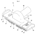
- FIG. 2 is a view illustrating a suction nozzle of FIG. 1 in detail
- FIG. 3 is a view illustrating a state in which a movable member of the suction nozzle of FIG. 2 is withdrawn
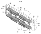
- FIG. 4 is a bottom view of the suction nozzle of FIG. 3 .
- FIG. 1 illustrates a canister type vacuum cleaner.
- a suction nozzle of the present invention may also be applied to an up-right type vacuum cleaner.
- a "floor surface” may be a surface to be cleaned, such as a carpet, as well as a floor of a living room or a sleeping room.
- a vacuum cleaner 1 may include a cleaner body 10 having a suction motor (not shown) which generates a suction force, and a suction unit 20 which is connected to the cleaner body 10 to suction air and foreign substances on a floor surface.
- the cleaner body 10 may include one or more wheels, and a dust container 110 in which dust separated from the air is stored.
- the suction unit 20 may include a suction nozzle 30 which is movable along the floor surface, and a connection mechanism which connects the suction nozzle 30 with the cleaner body 10.
- connection mechanism may include an extension tube 24 which is connected to the suction nozzle 30, a handle 22 which is connected to the extension tube 24, and a connection hose 23 which connects the handle 22 with the cleaner body 10.
- the suction nozzle 30 may include a suction part 310, and one or more movable members 320 and 330 which are movably connected to the suction part 310.
- the one or more movable members 320 and 330 may be installed to be inserted into or withdrawn from the suction part 310.
- the suction nozzle 30 may further include a connection tube 380 which is rotatably connected to a rear portion of the suction part 310.
- the extension tube 24 may be connected to the connection tube 380.
- a suction port 31 may be formed at the suction part 310, and the foreign substances suctioned through the suction port 31 may be moved to the dust container 110 of the cleaner body 10 through the connection tube 380 and the extension tube 24.
- First communication holes 321 and 331 may be provided at the one or more movable members 320 and 330. While the movable members 320 and 330 are inserted into the suction part 310, the first communication holes 321 and 331 may be aligned with the suction port 31. That is, the air may pass through the suction port 31 via the first communication holes 321 and 331.
- FIG. 2 illustrates an example in which two movable members 320 and 330 are connected to both sides of the suction part 310.
- the number of movable members 320 and 330 is not limited.
- the movable members 320 and 330 may include a first movable member 320 which is connected to one side of the suction part 310, and a second movable member 330 which is connected to the other side of the suction part 310.
- Each of the first movable member 320 and the second movable member 330 may be connected to the suction part 310 to be inserted therein or withdrawn therefrom.
- each of the first movable member 320 and the second movable member 330 may be slidingly inserted into the suction part 310 or withdrawn from the suction part 310. That is, a user may grip and then manually withdraw one or more of the first movable member 320 and the second movable member 330.
- the first movable member 320 and the second movable member 330 may be withdrawn from the suction part 310 away from each other, and may be inserted into the suction part 310 toward each other.
- the first movable member 320 and the second movable member 330 may be independently withdrawn from or inserted into the suction part 310. That is, one of the first movable member 320 and the second movable member 330 may be withdrawn from the suction part 310, or both of the first movable member 320 and the second movable member 330 may be withdrawn from the suction part 310.
- the first movable member 320 and the second movable member 330 may have the same structure as each other. However, lengths of the first movable member 320 and the second movable member 330 may be the same as or different from each other.
- a maximum withdrawn length of the first movable member 320 withdrawn from the suction part 310 may be different from that of the second movable member 330 withdrawn from the suction part 310.
- the first movable member 320 and the second movable member 330 may respectively have stoppers 322 and 332 which come in contact with side ends of the suction part 310 when they are inserted into the suction part 310.
- the stoppers 322 and 332 may include a first stopper 322 which is provided at the first movable member 320, and a second stopper 332 which is provided at the second movable member 330.
- a main brush 312 for cleaning the floor surface may be provided at the suction part 310.
- the main brush 312 may be formed to protrude downward from a lower surface of the suction part 310.
- first movable member 320 and the second movable member 330 may further include subsidiary brushes 324 and 334 for cleaning the floor surface.
- the subsidiary brushes 324 and 334 may include a first subsidiary brush 324 which is provided at the first movable member 320, and a second subsidiary brush 334 which is provided at the second movable member 330.
- the main brush 312 and the subsidiary brushes 324 and 334 may be commonly referred to as brushes 312, 324 and 334.
- the subsidiary brushes 324 and 334 may pass through the lower surface of the suction part 310.
- the suction part 310 may include a first brush slit 314 (referring to FIG. 7 ) which prevents interference with the subsidiary brushes 324 and 334 while the movable members 320 and 330 are being inserted into the suction part 310. That is, when the movable members 320 and 330 are inserted into the suction part 310, the subsidiary brushes 324 and 334 may be located in the first brush slit 314 (referring to FIG. 7 ).
- the suction nozzle 30 may further include a brush cleaning unit 340 which removes the foreign substances, such as hairs, attached to the main brush 312 or the subsidiary brushes 324 and 334.
- a brush cleaning unit 340 which removes the foreign substances, such as hairs, attached to the main brush 312 or the subsidiary brushes 324 and 334.
- the brush cleaning unit 340 may be moved in the same direction as an extension direction of the main brush 312 and the subsidiary brushes 324 and 334, and may clean the foreign substances attached to the main brush 312 and the subsidiary brushes 324 and 334.
- the suction nozzle 30 may further include a lever 350 which operates the brush cleaning unit 340.
- the brush cleaning unit 340 may be moved in the same direction as the extension direction of the main brush 312 and the subsidiary brushes 324 and 334 by the lever 350.
- the lever 350 may further include a transmission part (not shown) which transmits a force applied to the lever 350 to the brush cleaning unit 340 and moves the brush cleaning unit 340.
- the transmission part (not shown) may move the brush cleaning unit 340 with the force transmitted from the lever 350.
- the brush cleaning unit 340 may include a first cleaning part 341, and a second cleaning part 342 and a third cleaning part 344 which are connected to the first cleaning part 341 to be inserted thereinto or withdrawn therefrom. Each of the second cleaning part 342 and the third cleaning part 344 may be slidingly inserted into or withdrawn from the first cleaning part 341.
- the first cleaning part 341 may include an opening 32 which is in communication with the suction port 31.
- the second cleaning part 342 and the third cleaning part 344 may include second communication holes 347 and 349 which are in communication with the first communication holes 321 and 331, respectively.
- the second cleaning part 342 and the third cleaning part 344 may include stoppers 343 and 345, respectively.
- the stoppers 343 and 345 may come in contact with side ends of the first cleaning part 341 while the second cleaning part 342 and the third cleaning part 344 are being inserted into the first cleaning part 341.
- the stoppers 343 and 345 may include a third stopper 343 which is installed at the second cleaning part 342, and a fourth stopper 345 which is installed at the third cleaning part 344.
- FIG. 5 is a view illustrating a state in which the brush cleaning unit of FIG. 2 is moved down
- FIG. 6 is a view illustrating a state in which the movable member of the suction nozzle of FIG. 5 is withdrawn.
- the second cleaning part 342 and the third cleaning part 344 may further include guide parts 346 and 348 for coupling with the movable members, respectively.
- the guide parts 346 and 348 may include a first guide part 346 which is formed to protrude upward from the third stopper 343 provided at the brush cleaning unit 340, and a second guide part 348 which is formed to protrude upward from the fourth stopper 345.
- the first guide part 346 and the second guide part 348 may be inserted into the stoppers 322 and 332 of the movable members 320 and 330, respectively.
- the first guide part 346 may be inserted into the first stopper 322
- the second guide part 348 may be inserted into the second stopper 332.
- the second cleaning part 342 and the third cleaning part 344 are fixed to the first movable member 320 and the second movable member 330, respectively, the second cleaning part 342 may be moved with the first movable member 320, and the third cleaning part 344 may be moved with the second movable member 330. That is, while the movable members 320 and 330 are moved, a length of the brush cleaning unit 340 may be varied.
- the guide parts 346 and 348 may be provided with guide part stoppers (not shown) which prevent the guide parts 346 and 348 from being moved down beyond a predetermined distance. Accordingly, distance to which the brush cleaning unit 340 can move downward may be limited.
- the guide parts 346 and 348 may be provided at the first stopper 322 and the second stopper 332, instead of the third stopper 343 and the fourth stopper 345.
- FIG. 7 is a cross-sectional view taken along A-A' of FIG. 2
- FIG. 8 is a bottom view of the brush cleaning unit of FIG. 4 .
- the first movable member 320 may be inserted into the internal space of the suction part 310.
- the first movable member 320 may be slidingly moved in the internal space of the suction part 310, while the first subsidiary brush 324 passes through the suction part 310 and the brush cleaning unit 340.
- the first cleaning part 341 may include a first brush hole 341 a through which the main brush 312 passes.
- the main brush 312 may be inserted into the first brush hole 341 a, and may be fixed to the first cleaning part 341.
- the first brush hole 341 a may be formed at upper and lower portions of the first cleaning part 341.
- the first cleaning part 341 may include second brush slits 341 b and 341 c which prevent interference with the subsidiary brushes 324 and 334 when the movable members 320 and 330 are being inserted into or withdrawn from the suction part 310. That is, the subsidiary brushes 324 and 334 may be moved along the second brush slits 314b and 341 c while the movable members 320 and 330 are being inserted into the suction part 310.
- the second brush slits 314b and 341c may be formed at upper and lower ends of the first cleaning part 341.
- the second cleaning part 342 and the third cleaning part 344 may include second brush holes 342a and 344a through which the subsidiary brushes 324 and 334 pass.
- the subsidiary brushes 324 and 334 may be inserted into the second brush holes 324a and 344a, and may be fixed to the second cleaning part 342 and the third cleaning part 344.
- the second cleaning part 342 and the third cleaning part 344 may include third brush slits 342b and 344b which prevent interference with the main brush 312 during insertion into or withdrawal from the first cleaning part 341. That is, when the second cleaning part 342 and the third cleaning part 344 are inserted into the first cleaning part 341, the main brush 312 is located in the third brush slits 342b and 344b.
- the opening 32 of the first cleaning part 341, the second communication holes 347 and 349 of the second cleaning part 342 and the third cleaning part 344, the first communication holes 321 and 331 of the movable members 320 and 330 and the suction port 31 of the suction part 310 are aligned with each other.
- the air containing the dust may be suctioned into the suction port 31 through the opening 32, the second communication holes 347 and 349 and the first communication hole 321 and 331 by the suction force generated by the suction motor.
- the main brush 312 and the subsidiary brushes 324 and 334 may protrude below the brush cleaning unit 340.
- the surface to be cleaned may be cleaned by the main brush 312 and the subsidiary brushes 324 and 334 which protrude below the brush cleaning unit 340.
- the length of the brush cleaning unit 340 may be increased. That is, the second cleaning part 342 and the third cleaning part 344 which are connected to the movable members 320 and 330 may be withdrawn from the first cleaning part 341 along with the movable members 320 and 330.
- a transverse width of an area to be cleaned which will be cleaned by the main brush 312 and the subsidiary brushes 324 and 334 may be increased.
- the brush cleaning unit 340 may be moved down, as illustrated in FIG. 5 . While the brush cleaning unit 340 is being moved down as illustrated in FIG. 5 , the brush cleaning unit 340 may remove the foreign substances or the hairs attached to the main brush 312 and the subsidiary brushes 324 and 334 from the main brush 312 and the subsidiary brushes 324 and 334.
- the brush cleaning unit 340 in a state in which the brush cleaning unit 340 is in contact with the suction part 310, the brush cleaning unit 340 is moved toward ends of the main brush 312 and the subsidiary brushes 324 and 334 and moves the foreign substances attached to the main brush 312 and the subsidiary brushes 324 and 334 away from the main brush 312 and the subsidiary brushes 324 and 334, and thus the foreign substances may be removed from the main brush 312 and the subsidiary brushes 324 and 334.
- the brush cleaning unit 340 may be moved down, and may remove the foreign substances or the hairs attached to the main brush 312 and the subsidiary brushes 324 and 334.
- the brush cleaning unit 340 may reciprocate between upper ends and lower ends of the brushes 312, 324 and 334 while the brushes 312, 324 and 334 pass therethrough, and thus the foreign substances attached to the brushes 312, 324 and 334 may be removed. Accordingly, cleaning efficiency by the brushes 312, 324 and 334 may be increased.
- the brush cleaning unit 340 may extend along with the movable members 320 and 330. Therefore, it can be used in a nozzle of a cleaner of which a length is variable.
- FIG. 9 is a perspective view of a suction nozzle according to a second embodiment of the present invention
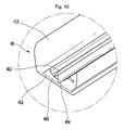
- FIG. 10 is a perspective view illustrating a lower structure of the suction nozzle according to the second embodiment of the present invention
- FIG. 11 is a cross-sectional view illustrating an internal structure of the suction nozzle according to the second embodiment of the present invention.
- the suction nozzle 40 may include a nozzle body 410 having a suction port 411 for suctioning the air containing the dust.
- the suction port 411 may be formed at a bottom of the nozzle body 410, and may be formed to extend to the left and right of the nozzle body 410.
- the suction nozzle 40 may further include a connection tube 480 which is connected to a rear side of the nozzle body 410.
- the connection tube 480 may be rotatably connected to the nozzle body 410.
- the suction nozzle 40 may further include a cleaning part 460 for cleaning the floor surface, and a driving unit 430 for driving the cleaning part 460.
- the cleaning part 460 may include a cleaning body 462, and a brush member 464 which is provided at the cleaning body 462.
- the brush member 464 may include a brush or may be formed of a rubber material. The brush member 464 may slide along the floor surface and sweep up the dust on the floor surface.
- the brush member 464 may be slidingly coupled to the cleaning body 462.
- the driving unit 430 may drive the cleaning part 460 so that the brush member 464 of the cleaning part 460 reciprocates within a predetermined range.
- the driving unit 430 may drive the cleaning part 460 so that the brush member 464 of the cleaning part 460 performs a pendulum motion within a predetermined angular range which is smaller than 360 degrees.
- the driving unit 430 may include a driving part 432 which generates a driving force, and a power transmission part which transmits the driving force of the driving part 432 to the cleaning part 460.
- the driving part 432 may be a motor.
- the power transmission part serves to convert a rotational force generated by the motor into a linear motion.
- the power transmission part may include a rotational part 434 which is connected to the driving part 432, and a movable member 440 which receives the driving force of the driving part 432 from the rotational part 434.
- the movable member 440 may receive a rotational force of the rotational part 434 and may perform the linear motion.
- the rotational part 434 may be rotatably connected to a fixed shaft 436 which is fixed to the nozzle body 410.
- a shaft of the motor may be connected to the rotational part 434.
- the driving part 432 may be fixed to the nozzle body 410 by the fixed shaft 436.
- a support port for supporting the driving part 432 may be provided at the nozzle body 410.
- the shaft of the motor may pass through the rotational part 434, and may be connected to the fixed shaft 436.
- the nozzle body 410 may include a first chamber 412 in which the cleaning part 460 is located, and a second chamber 413 in which the driving part 432 is located.
- the first chamber 412 and the second chamber 413 may be divided by a partition wall 415.
- the partition wall 415 may have an opening 414 through which a first space 412 is in communication with a second space 413.
- the movable member 440 may pass through the opening 414.
- the partition wall 415 may be removed from the nozzle body 410. In this case, a single chamber may be formed in the nozzle body 410.
- the cleaning part 460 may be rotatably connected to the movable member 440. That is, the cleaning part 460 may be connected to the movable member 440 in an idle state.
- An accommodation part 452 in which the cleaning part 460 is located may be provided at the movable member 440.
- the accommodation part 452 may be provided at a lower portion of the movable member 440.
- the movable member 440 may include a first limiting surface 453 and a second limiting surface 454 which limit a rotational range of the brush member 464 when the brush member 464 performs the pendulum motion.
- the first limiting surface 453 and the second limiting surface 454 may be disposed to be farther apart from each other toward the bottom.
- An angle ⁇ between the first limiting surface 453 and the second limiting surface 454 may be less than 135 degrees.
- the angle between the first limiting surface 453 and the second limiting surface 454 is more than the 135 degrees, there is a problem that a length of the suction port in a forward and backward direction should be increased to prevent interference with the brush member 464 due to an increase in an angle of the pendulum motion of the brush member 464.
- the angle ⁇ between the first limiting surface 453 and the second limiting surface 454 be less than 135 degrees.
- the brush member 464 of the cleaning part 460 may reciprocate within an angular range between the first limiting surface 453 and the second limiting surface 454.
- a lower end of the cleaning part 460 e.g., a lower end of the brush member 464, may pass through a lower side of the suction port 411, and may protrude from the lower side of the suction port 411.
- a subsidiary suction port 416 through which the air is suctioned may be provided at an upper portion of the nozzle body 410.
- the air suctioned through the subsidiary suction port 416 may flow to a connection portion between the rotational part 434 and the movable member 440.
- the rotational part 434 In a state in which the rotational part 434 is connected to the movable member 440, when fine dust or sand is at the connection portion, the rotational part 434 may not rotate smoothly, or the movable member 440 may not perform the linear motion smoothly. Therefore, in the embodiment, since the subsidiary suction port 416 is formed at the nozzle body 410, the fine dust or the sand may be removed from the connection portion by the air suctioned through the subsidiary suction port 416.
- FIG. 12 is a perspective view of the power transmission part according to the second embodiment of the present invention.
- the movable member 440 may include a first member 442 which extends horizontally, and a second member 450 which extends downward from the first member 442.
- the second member 450 may extend downward from one end of the first member 442.
- the first member 442 may pass through the opening 414 of the partition wall 415.
- the cleaning part 460 may be rotatably connected to the second member 450.
- An accommodation part 443 in which the rotational part 434 is accommodated may be provided at the first member 442.
- the accommodation part 443 may be a slit or a groove.
- the groove may be formed by recessing an upper surface of the first member 442 downward.
- the rotational part 434 may have a plurality of gear teeth 435 which are formed within a predetermined angular range in a circumferential direction. That is, the rotational part 434 may be a partial gear in which the gear teeth are formed at a part thereof.
- the accommodation part 443 may include a first gear part 444 and a second gear part 445.
- the first gear part 444 and the second gear part 445 may be disposed to face each other, and each of the first gear part 444 and the second gear part 445 may include the plurality of gear teeth.
- the plurality of gear teeth in each of the first gear part 444 and the second gear part 445 may be disposed linearly.
- first gear part 444 and the second gear part 445 serve as rack gears
- rotational part 434 i.e., the partial gear
- the rotational part 434 may be rotated in one direction. While the rotational part 434 is rotated in the one direction, the gear teeth 435 of the rotational part 434 may be engaged with the first gear part 444, and may move the movable member 440 in the one direction, and when the rotational part 434 is further rotated in the one direction, the gear teeth 435 of the rotational part 434 may be engaged with the second gear part 445, and may move the movable member 440 in the direction opposite to the one direction.
- FIG. 13 is a view illustrating a first guide mechanism for guiding movement of the movable member according to the second embodiment of the present invention
- FIG. 14 is view illustrating a second guide mechanism for guiding movement of the movable member according to the second embodiment of the present invention.
- the nozzle body 410 may have a first guide mechanism 421 and 422 which guides the linear motion (forward and backward movement in the embodiment) of the movable member 440.
- the first guide mechanism 421 and 422 may include a first guide rib 421, and a second guide rib 422 which is vertically spaced apart from the first guide rib 421.
- a part of the first member 442 may be located between the first guide rib 421 and the second guide rib 422.
- the movable member 440 may stably perform the linear motion, while located between the first guide rib 421 and the second guide rib 422.
- the first guide mechanism 421 and 422 serves as a guide rail.
- the nozzle body 410 may have a second guide mechanism 424 which guides the linear motion of the movable member 440.
- the second guide mechanism 424 may be a groove provided at the nozzle body 410.
- the movable member 440 may have a guide protrusion 456 which is accommodated in the groove.
- the guide protrusion 456 may be provided at the second member 450.
- the first guide mechanism may be a groove which accommodates a part of the movable member.
- the second guide mechanism may include a plurality of guide ribs which are vertically spaced apart from each other.
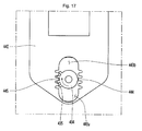
- FIGS. 15 to 18 are views illustrating an operation of the power transmission part according to the second embodiment of the present invention
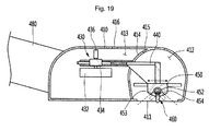
- FIG. 19 is a cross-sectional view illustrating a state in which the brush member of the cleaning part is caused to reciprocate by the driving unit according to one embodiment of the present invention.
- the accommodation part 443 of the movable member 440 may further include a first space 443a and a second space 443b in which the rotational part 434 may be located while being rotated.
- the rotational part 434 may be located between the first space 443a and the second space 443b and between the first gear part 444 and the second gear part 445.
- the gear teeth 435 of the rotational part 434 may be engaged with the first gear part 444.
- the rotational force of the rotational part 434 is transmitted to the first gear part 444 by the gear teeth 435, as illustrated in FIG. 16 , and the movable member 440 performs the linear motion in an A direction.
- the movable member 440 performs the linear reciprocation motion once. While the movable member 440 performs the linear reciprocation motion, the brush member 464 of the cleaning part 460 reciprocates at least once. While the brush member 464 reciprocates at least once, the brush member 464 cleans the floor surface facing the suction port 411 at least twice.
- a speed of the brush member 464 has a maximum value when the brush member 464 is in contact with the floor surface, and thus the dust on the floor surface may be effectively swept up by the brush member 464.
- the brush member 464 may clean the floor surface at least twice. Therefore, a speed of the driving part may be reduced, and thus a power consumption of the driving may be reduced.
- FIG. 20 is a cross-sectional view illustrating a suction nozzle according to the third embodiment of the present invention.
- This embodiment is the same as the second embodiment except for the type of the driving part. Therefore, hereinafter, only a characteristic part of the embodiment will be described.
- a driving unit 430 may include a driving part 472 which is rotated by a flow of the air suctioned through the suction port.
- the driving part 372 may be a turbine having a plurality of blades.
- a rotational speed of the turbine may be increased as a size of the turbine is increased.
- the nozzle body 410 may further have an additional suction port 417 for suctioning the air toward the turbine.
- the additional suction port 417 may be located at a rear side of the nozzle body 410.
- the power of the driving part has been described as being directly transmitted to the rotational part.
- the power of the driving part may be transmitted to the rotational part by one or more gears or belts.
- a degree of arrangement freedom of the driving part can be enhanced, and a length of the movable member in a forward and backward direction can be reduced.
- the driving unit of the second embodiment or the third embodiment may be applied to the first embodiment.
- the second cleaning part and the third cleaning part can perform the linear reciprocation motion within a predetermined range, and can automatically be caused to reciprocate by the driving unit.
- the driving unit can be disposed at the suction part, and the movable member may be connected to one or more stoppers of the second cleaning part and the third cleaning part.
Landscapes
- Engineering & Computer Science (AREA)
- Mechanical Engineering (AREA)
- Nozzles For Electric Vacuum Cleaners (AREA)
Applications Claiming Priority (2)
| Application Number | Priority Date | Filing Date | Title |
|---|---|---|---|
| KR1020140169812A KR101653458B1 (ko) | 2014-12-01 | 2014-12-01 | 청소기의 노즐 및 진공 청소기 |
| KR1020140177725A KR101620234B1 (ko) | 2014-12-10 | 2014-12-10 | 청소기의 노즐 및 진공 청소기 |
Publications (3)
| Publication Number | Publication Date |
|---|---|
| EP3028618A2 true EP3028618A2 (de) | 2016-06-08 |
| EP3028618A3 EP3028618A3 (de) | 2016-10-12 |
| EP3028618B1 EP3028618B1 (de) | 2018-02-07 |
Family
ID=54770951
Family Applications (1)
| Application Number | Title | Priority Date | Filing Date |
|---|---|---|---|
| EP15197313.8A Active EP3028618B1 (de) | 2014-12-01 | 2015-12-01 | Staubsauger und düse für staubsauger |
Country Status (3)
| Country | Link |
|---|---|
| US (1) | US9655487B2 (de) |
| EP (1) | EP3028618B1 (de) |
| CN (1) | CN105640427B (de) |
Families Citing this family (6)
| Publication number | Priority date | Publication date | Assignee | Title |
|---|---|---|---|---|
| US9517396B2 (en) * | 2014-01-24 | 2016-12-13 | John Albert IRELAND | Curling broom incorporating a motor |
| US10918186B2 (en) * | 2018-02-15 | 2021-02-16 | Edward Ott | Self cleaning brush with hair collection |
| GB2590497B (en) * | 2019-12-20 | 2023-12-27 | Techtronic Cordless Gp | A cleaner head for a cleaning appliance |
| CN113665119A (zh) * | 2021-08-18 | 2021-11-19 | 深圳市金石三维打印科技有限公司 | 一种3d打印机平台用清理装置 |
| CN114098511B (zh) * | 2021-10-15 | 2022-09-13 | 宁波万盛实业有限公司 | 一种吸嘴大小可调的智能吸尘器 |
| USD1073229S1 (en) * | 2023-08-22 | 2025-04-29 | Xiamen Xiangdao Information Technology Co., Ltd. | Vacuum cleaner electric direct drive floor brush |
Citations (1)
| Publication number | Priority date | Publication date | Assignee | Title |
|---|---|---|---|---|
| KR20130023632A (ko) | 2011-08-29 | 2013-03-08 | 엘지전자 주식회사 | 진공 청소기 |
Family Cites Families (17)
| Publication number | Priority date | Publication date | Assignee | Title |
|---|---|---|---|---|
| JPS57196454U (de) | 1981-06-11 | 1982-12-13 | ||
| JPS5819218A (ja) * | 1981-07-23 | 1983-02-04 | 株式会社東芝 | 電気掃除機の吸込口体 |
| JPS63121055U (de) * | 1987-01-30 | 1988-08-05 | ||
| KR910002899B1 (ko) | 1988-04-22 | 1991-05-09 | 박영근 | 회전-왕복운동 변환장치 및 이를 이용한 내연기관 |
| JP2002112930A (ja) | 2000-10-12 | 2002-04-16 | Misako Sato | 電気掃除機における吸込区分化清掃の方法と装置 |
| US6991262B1 (en) * | 2002-12-07 | 2006-01-31 | Gary Dean Ragner | Pivotal body for multi-function nozzles |
| KR200312437Y1 (ko) | 2003-01-29 | 2003-05-12 | 이상윤 | 빗자루 |
| KR100545266B1 (ko) * | 2003-10-20 | 2006-01-24 | 삼성광주전자 주식회사 | 진공청소기의 접이식 브러시 |
| KR20050038442A (ko) * | 2003-10-22 | 2005-04-27 | 삼성광주전자 주식회사 | 진공청소기의 접이식 흡입 브러시 |
| AT413789B (de) | 2004-10-29 | 2006-06-15 | Friedhelm Michael Tomczak | Staubsaugerbürste |
| KR100638205B1 (ko) | 2004-12-30 | 2006-10-26 | 엘지전자 주식회사 | 진공 청소기 |
| KR100968335B1 (ko) | 2008-05-26 | 2010-07-08 | 엘지전자 주식회사 | 청소기 |
| EP2253258B1 (de) | 2009-05-15 | 2016-10-19 | Samsung Electronics Co., Ltd. | Selbständige Reinigungsmaschine |
| GB2470406B (en) * | 2009-05-22 | 2012-04-11 | Dyson Technology Ltd | Attachment for vacuum cleaning appliance |
| CN102028431A (zh) * | 2009-09-24 | 2011-04-27 | 乐金电子(天津)电器有限公司 | 吸尘器刷头 |
| KR101450996B1 (ko) | 2013-01-08 | 2014-10-15 | 엘지전자 주식회사 | 청소기의 노즐 |
| CN203328164U (zh) * | 2013-06-26 | 2013-12-11 | 无锡同心塑料制品有限公司 | 一种自动清洁梳 |
-
2015
- 2015-12-01 US US14/955,577 patent/US9655487B2/en not_active Expired - Fee Related
- 2015-12-01 EP EP15197313.8A patent/EP3028618B1/de active Active
- 2015-12-01 CN CN201510867575.8A patent/CN105640427B/zh active Active
Patent Citations (1)
| Publication number | Priority date | Publication date | Assignee | Title |
|---|---|---|---|---|
| KR20130023632A (ko) | 2011-08-29 | 2013-03-08 | 엘지전자 주식회사 | 진공 청소기 |
Also Published As
| Publication number | Publication date |
|---|---|
| EP3028618B1 (de) | 2018-02-07 |
| CN105640427B (zh) | 2018-06-05 |
| CN105640427A (zh) | 2016-06-08 |
| US20160150928A1 (en) | 2016-06-02 |
| EP3028618A3 (de) | 2016-10-12 |
| US9655487B2 (en) | 2017-05-23 |
Similar Documents
| Publication | Publication Date | Title |
|---|---|---|
| EP3028618B1 (de) | Staubsauger und düse für staubsauger | |
| US8544144B2 (en) | Vacuum cleaner and dust separation apparatus thereof | |
| US10117551B2 (en) | Handheld vacuum cleaner | |
| KR102021922B1 (ko) | 청소기 | |
| EP3231344A1 (de) | Saugkörper für aufrechten reiniger | |
| EP2848173A1 (de) | Staubsauger | |
| JP5609947B2 (ja) | ノズル及びこれを用いた電気掃除機 | |
| CN107115064A (zh) | 用于家用电器的紧凑型伸缩式延伸件以及相关的家用电器 | |
| US20070209149A1 (en) | Vacuum cleaner | |
| KR100968335B1 (ko) | 청소기 | |
| KR101331684B1 (ko) | 자동 청소기 | |
| EP1767132A2 (de) | Saugdüseanordnung für einen Staubsauger und Staubsauger umfassend einer sochen Saugdüseanordnung | |
| WO2017068679A1 (ja) | バキューム掃除機用の掃除機ヘッド、及びバキューム掃除機 | |
| CN105358028A (zh) | 集尘装置 | |
| EP3479744B1 (de) | Düse für reiniger und staubsauger | |
| KR101055910B1 (ko) | 진공 청소기의 노즐 | |
| KR20090121813A (ko) | 청소기의 노즐 | |
| KR101620234B1 (ko) | 청소기의 노즐 및 진공 청소기 | |
| KR101653458B1 (ko) | 청소기의 노즐 및 진공 청소기 | |
| KR20110077806A (ko) | 진공청소기의 먼지통 | |
| KR100988719B1 (ko) | 진공 청소기 | |
| CN104337465A (zh) | 真空吸尘器 | |
| JP4912836B2 (ja) | 電気掃除機 | |
| JP5253885B2 (ja) | 吸込口体および電気掃除機 | |
| KR101281927B1 (ko) | 흡입구체 및 전기 청소기 |
Legal Events
| Date | Code | Title | Description |
|---|---|---|---|
| PUAI | Public reference made under article 153(3) epc to a published international application that has entered the european phase |
Free format text: ORIGINAL CODE: 0009012 |
|
| 17P | Request for examination filed |
Effective date: 20160101 |
|
| AK | Designated contracting states |
Kind code of ref document: A2 Designated state(s): AL AT BE BG CH CY CZ DE DK EE ES FI FR GB GR HR HU IE IS IT LI LT LU LV MC MK MT NL NO PL PT RO RS SE SI SK SM TR |
|
| AX | Request for extension of the european patent |
Extension state: BA ME |
|
| PUAL | Search report despatched |
Free format text: ORIGINAL CODE: 0009013 |
|
| AK | Designated contracting states |
Kind code of ref document: A3 Designated state(s): AL AT BE BG CH CY CZ DE DK EE ES FI FR GB GR HR HU IE IS IT LI LT LU LV MC MK MT NL NO PL PT RO RS SE SI SK SM TR |
|
| AX | Request for extension of the european patent |
Extension state: BA ME |
|
| RIC1 | Information provided on ipc code assigned before grant |
Ipc: A47L 9/06 20060101AFI20160902BHEP |
|
| RBV | Designated contracting states (corrected) |
Designated state(s): AL AT BE BG CH CY CZ DE DK EE ES FI FR GB GR HR HU IE IS IT LI LT LU LV MC MK MT NL NO PL PT RO RS SE SI SK SM TR |
|
| GRAP | Despatch of communication of intention to grant a patent |
Free format text: ORIGINAL CODE: EPIDOSNIGR1 |
|
| INTG | Intention to grant announced |
Effective date: 20170724 |
|
| GRAS | Grant fee paid |
Free format text: ORIGINAL CODE: EPIDOSNIGR3 |
|
| GRAA | (expected) grant |
Free format text: ORIGINAL CODE: 0009210 |
|
| AK | Designated contracting states |
Kind code of ref document: B1 Designated state(s): AL AT BE BG CH CY CZ DE DK EE ES FI FR GB GR HR HU IE IS IT LI LT LU LV MC MK MT NL NO PL PT RO RS SE SI SK SM TR |
|
| REG | Reference to a national code |
Ref country code: GB Ref legal event code: FG4D |
|
| REG | Reference to a national code |
Ref country code: AT Ref legal event code: REF Ref document number: 968469 Country of ref document: AT Kind code of ref document: T Effective date: 20180215 Ref country code: CH Ref legal event code: EP |
|
| REG | Reference to a national code |
Ref country code: IE Ref legal event code: FG4D |
|
| REG | Reference to a national code |
Ref country code: DE Ref legal event code: R096 Ref document number: 602015007915 Country of ref document: DE |
|
| REG | Reference to a national code |
Ref country code: NL Ref legal event code: MP Effective date: 20180207 |
|
| REG | Reference to a national code |
Ref country code: AT Ref legal event code: MK05 Ref document number: 968469 Country of ref document: AT Kind code of ref document: T Effective date: 20180207 |
|
| PG25 | Lapsed in a contracting state [announced via postgrant information from national office to epo] |
Ref country code: FI Free format text: LAPSE BECAUSE OF FAILURE TO SUBMIT A TRANSLATION OF THE DESCRIPTION OR TO PAY THE FEE WITHIN THE PRESCRIBED TIME-LIMIT Effective date: 20180207 Ref country code: NO Free format text: LAPSE BECAUSE OF FAILURE TO SUBMIT A TRANSLATION OF THE DESCRIPTION OR TO PAY THE FEE WITHIN THE PRESCRIBED TIME-LIMIT Effective date: 20180507 Ref country code: HR Free format text: LAPSE BECAUSE OF FAILURE TO SUBMIT A TRANSLATION OF THE DESCRIPTION OR TO PAY THE FEE WITHIN THE PRESCRIBED TIME-LIMIT Effective date: 20180207 Ref country code: LT Free format text: LAPSE BECAUSE OF FAILURE TO SUBMIT A TRANSLATION OF THE DESCRIPTION OR TO PAY THE FEE WITHIN THE PRESCRIBED TIME-LIMIT Effective date: 20180207 Ref country code: CY Free format text: LAPSE BECAUSE OF FAILURE TO SUBMIT A TRANSLATION OF THE DESCRIPTION OR TO PAY THE FEE WITHIN THE PRESCRIBED TIME-LIMIT Effective date: 20180207 Ref country code: ES Free format text: LAPSE BECAUSE OF FAILURE TO SUBMIT A TRANSLATION OF THE DESCRIPTION OR TO PAY THE FEE WITHIN THE PRESCRIBED TIME-LIMIT Effective date: 20180207 Ref country code: NL Free format text: LAPSE BECAUSE OF FAILURE TO SUBMIT A TRANSLATION OF THE DESCRIPTION OR TO PAY THE FEE WITHIN THE PRESCRIBED TIME-LIMIT Effective date: 20180207 |
|
| PG25 | Lapsed in a contracting state [announced via postgrant information from national office to epo] |
Ref country code: IS Free format text: LAPSE BECAUSE OF FAILURE TO SUBMIT A TRANSLATION OF THE DESCRIPTION OR TO PAY THE FEE WITHIN THE PRESCRIBED TIME-LIMIT Effective date: 20180607 Ref country code: BG Free format text: LAPSE BECAUSE OF FAILURE TO SUBMIT A TRANSLATION OF THE DESCRIPTION OR TO PAY THE FEE WITHIN THE PRESCRIBED TIME-LIMIT Effective date: 20180507 Ref country code: GR Free format text: LAPSE BECAUSE OF FAILURE TO SUBMIT A TRANSLATION OF THE DESCRIPTION OR TO PAY THE FEE WITHIN THE PRESCRIBED TIME-LIMIT Effective date: 20180508 Ref country code: SE Free format text: LAPSE BECAUSE OF FAILURE TO SUBMIT A TRANSLATION OF THE DESCRIPTION OR TO PAY THE FEE WITHIN THE PRESCRIBED TIME-LIMIT Effective date: 20180207 Ref country code: AT Free format text: LAPSE BECAUSE OF FAILURE TO SUBMIT A TRANSLATION OF THE DESCRIPTION OR TO PAY THE FEE WITHIN THE PRESCRIBED TIME-LIMIT Effective date: 20180207 Ref country code: LV Free format text: LAPSE BECAUSE OF FAILURE TO SUBMIT A TRANSLATION OF THE DESCRIPTION OR TO PAY THE FEE WITHIN THE PRESCRIBED TIME-LIMIT Effective date: 20180207 Ref country code: PL Free format text: LAPSE BECAUSE OF FAILURE TO SUBMIT A TRANSLATION OF THE DESCRIPTION OR TO PAY THE FEE WITHIN THE PRESCRIBED TIME-LIMIT Effective date: 20180207 Ref country code: RS Free format text: LAPSE BECAUSE OF FAILURE TO SUBMIT A TRANSLATION OF THE DESCRIPTION OR TO PAY THE FEE WITHIN THE PRESCRIBED TIME-LIMIT Effective date: 20180207 |
|
| PG25 | Lapsed in a contracting state [announced via postgrant information from national office to epo] |
Ref country code: RO Free format text: LAPSE BECAUSE OF FAILURE TO SUBMIT A TRANSLATION OF THE DESCRIPTION OR TO PAY THE FEE WITHIN THE PRESCRIBED TIME-LIMIT Effective date: 20180207 Ref country code: EE Free format text: LAPSE BECAUSE OF FAILURE TO SUBMIT A TRANSLATION OF THE DESCRIPTION OR TO PAY THE FEE WITHIN THE PRESCRIBED TIME-LIMIT Effective date: 20180207 Ref country code: IT Free format text: LAPSE BECAUSE OF FAILURE TO SUBMIT A TRANSLATION OF THE DESCRIPTION OR TO PAY THE FEE WITHIN THE PRESCRIBED TIME-LIMIT Effective date: 20180207 Ref country code: AL Free format text: LAPSE BECAUSE OF FAILURE TO SUBMIT A TRANSLATION OF THE DESCRIPTION OR TO PAY THE FEE WITHIN THE PRESCRIBED TIME-LIMIT Effective date: 20180207 |
|
| REG | Reference to a national code |
Ref country code: DE Ref legal event code: R097 Ref document number: 602015007915 Country of ref document: DE |
|
| PG25 | Lapsed in a contracting state [announced via postgrant information from national office to epo] |
Ref country code: SK Free format text: LAPSE BECAUSE OF FAILURE TO SUBMIT A TRANSLATION OF THE DESCRIPTION OR TO PAY THE FEE WITHIN THE PRESCRIBED TIME-LIMIT Effective date: 20180207 Ref country code: CZ Free format text: LAPSE BECAUSE OF FAILURE TO SUBMIT A TRANSLATION OF THE DESCRIPTION OR TO PAY THE FEE WITHIN THE PRESCRIBED TIME-LIMIT Effective date: 20180207 Ref country code: DK Free format text: LAPSE BECAUSE OF FAILURE TO SUBMIT A TRANSLATION OF THE DESCRIPTION OR TO PAY THE FEE WITHIN THE PRESCRIBED TIME-LIMIT Effective date: 20180207 Ref country code: SM Free format text: LAPSE BECAUSE OF FAILURE TO SUBMIT A TRANSLATION OF THE DESCRIPTION OR TO PAY THE FEE WITHIN THE PRESCRIBED TIME-LIMIT Effective date: 20180207 |
|
| PLBE | No opposition filed within time limit |
Free format text: ORIGINAL CODE: 0009261 |
|
| STAA | Information on the status of an ep patent application or granted ep patent |
Free format text: STATUS: NO OPPOSITION FILED WITHIN TIME LIMIT |
|
| 26N | No opposition filed |
Effective date: 20181108 |
|
| PG25 | Lapsed in a contracting state [announced via postgrant information from national office to epo] |
Ref country code: SI Free format text: LAPSE BECAUSE OF FAILURE TO SUBMIT A TRANSLATION OF THE DESCRIPTION OR TO PAY THE FEE WITHIN THE PRESCRIBED TIME-LIMIT Effective date: 20180207 |
|
| REG | Reference to a national code |
Ref country code: CH Ref legal event code: PL |
|
| PG25 | Lapsed in a contracting state [announced via postgrant information from national office to epo] |
Ref country code: MC Free format text: LAPSE BECAUSE OF FAILURE TO SUBMIT A TRANSLATION OF THE DESCRIPTION OR TO PAY THE FEE WITHIN THE PRESCRIBED TIME-LIMIT Effective date: 20180207 Ref country code: LU Free format text: LAPSE BECAUSE OF NON-PAYMENT OF DUE FEES Effective date: 20181201 |
|
| REG | Reference to a national code |
Ref country code: IE Ref legal event code: MM4A |
|
| REG | Reference to a national code |
Ref country code: BE Ref legal event code: MM Effective date: 20181231 |
|
| PG25 | Lapsed in a contracting state [announced via postgrant information from national office to epo] |
Ref country code: FR Free format text: LAPSE BECAUSE OF NON-PAYMENT OF DUE FEES Effective date: 20181231 Ref country code: IE Free format text: LAPSE BECAUSE OF NON-PAYMENT OF DUE FEES Effective date: 20181201 |
|
| PG25 | Lapsed in a contracting state [announced via postgrant information from national office to epo] |
Ref country code: BE Free format text: LAPSE BECAUSE OF NON-PAYMENT OF DUE FEES Effective date: 20181231 |
|
| PG25 | Lapsed in a contracting state [announced via postgrant information from national office to epo] |
Ref country code: CH Free format text: LAPSE BECAUSE OF NON-PAYMENT OF DUE FEES Effective date: 20181231 Ref country code: LI Free format text: LAPSE BECAUSE OF NON-PAYMENT OF DUE FEES Effective date: 20181231 |
|
| PG25 | Lapsed in a contracting state [announced via postgrant information from national office to epo] |
Ref country code: MT Free format text: LAPSE BECAUSE OF NON-PAYMENT OF DUE FEES Effective date: 20181201 |
|
| PG25 | Lapsed in a contracting state [announced via postgrant information from national office to epo] |
Ref country code: TR Free format text: LAPSE BECAUSE OF FAILURE TO SUBMIT A TRANSLATION OF THE DESCRIPTION OR TO PAY THE FEE WITHIN THE PRESCRIBED TIME-LIMIT Effective date: 20180207 |
|
| PG25 | Lapsed in a contracting state [announced via postgrant information from national office to epo] |
Ref country code: PT Free format text: LAPSE BECAUSE OF FAILURE TO SUBMIT A TRANSLATION OF THE DESCRIPTION OR TO PAY THE FEE WITHIN THE PRESCRIBED TIME-LIMIT Effective date: 20180207 |
|
| PG25 | Lapsed in a contracting state [announced via postgrant information from national office to epo] |
Ref country code: HU Free format text: LAPSE BECAUSE OF FAILURE TO SUBMIT A TRANSLATION OF THE DESCRIPTION OR TO PAY THE FEE WITHIN THE PRESCRIBED TIME-LIMIT; INVALID AB INITIO Effective date: 20151201 Ref country code: MK Free format text: LAPSE BECAUSE OF NON-PAYMENT OF DUE FEES Effective date: 20180207 |
|
| PGFP | Annual fee paid to national office [announced via postgrant information from national office to epo] |
Ref country code: GB Payment date: 20231106 Year of fee payment: 9 |
|
| GBPC | Gb: european patent ceased through non-payment of renewal fee |
Effective date: 20241201 |
|
| PG25 | Lapsed in a contracting state [announced via postgrant information from national office to epo] |
Ref country code: GB Free format text: LAPSE BECAUSE OF NON-PAYMENT OF DUE FEES Effective date: 20241201 |
|
| PGFP | Annual fee paid to national office [announced via postgrant information from national office to epo] |
Ref country code: DE Payment date: 20251105 Year of fee payment: 11 |