EP3028620B1 - Aspirateur et appareil de collecte de poussière - Google Patents
Aspirateur et appareil de collecte de poussière Download PDFInfo
- Publication number
- EP3028620B1 EP3028620B1 EP15197300.5A EP15197300A EP3028620B1 EP 3028620 B1 EP3028620 B1 EP 3028620B1 EP 15197300 A EP15197300 A EP 15197300A EP 3028620 B1 EP3028620 B1 EP 3028620B1
- Authority
- EP
- European Patent Office
- Prior art keywords
- dust
- pressing plate
- dust storage
- cover
- plate support
- Prior art date
- Legal status (The legal status is an assumption and is not a legal conclusion. Google has not performed a legal analysis and makes no representation as to the accuracy of the status listed.)
- Active
Links
Images


Classifications
-
- A—HUMAN NECESSITIES
- A47—FURNITURE; DOMESTIC ARTICLES OR APPLIANCES; COFFEE MILLS; SPICE MILLS; SUCTION CLEANERS IN GENERAL
- A47L—DOMESTIC WASHING OR CLEANING; SUCTION CLEANERS IN GENERAL
- A47L9/00—Details or accessories of suction cleaners, e.g. mechanical means for controlling the suction or for effecting pulsating action; Storing devices specially adapted to suction cleaners or parts thereof; Carrying-vehicles specially adapted for suction cleaners
- A47L9/10—Filters; Dust separators; Dust removal; Automatic exchange of filters
- A47L9/106—Dust removal
- A47L9/108—Dust compression means
-
- A—HUMAN NECESSITIES
- A47—FURNITURE; DOMESTIC ARTICLES OR APPLIANCES; COFFEE MILLS; SPICE MILLS; SUCTION CLEANERS IN GENERAL
- A47L—DOMESTIC WASHING OR CLEANING; SUCTION CLEANERS IN GENERAL
- A47L9/00—Details or accessories of suction cleaners, e.g. mechanical means for controlling the suction or for effecting pulsating action; Storing devices specially adapted to suction cleaners or parts thereof; Carrying-vehicles specially adapted for suction cleaners
- A47L9/10—Filters; Dust separators; Dust removal; Automatic exchange of filters
- A47L9/16—Arrangement or disposition of cyclones or other devices with centrifugal action
-
- A—HUMAN NECESSITIES
- A47—FURNITURE; DOMESTIC ARTICLES OR APPLIANCES; COFFEE MILLS; SPICE MILLS; SUCTION CLEANERS IN GENERAL
- A47L—DOMESTIC WASHING OR CLEANING; SUCTION CLEANERS IN GENERAL
- A47L9/00—Details or accessories of suction cleaners, e.g. mechanical means for controlling the suction or for effecting pulsating action; Storing devices specially adapted to suction cleaners or parts thereof; Carrying-vehicles specially adapted for suction cleaners
- A47L9/10—Filters; Dust separators; Dust removal; Automatic exchange of filters
- A47L9/102—Dust separators
-
- A—HUMAN NECESSITIES
- A47—FURNITURE; DOMESTIC ARTICLES OR APPLIANCES; COFFEE MILLS; SPICE MILLS; SUCTION CLEANERS IN GENERAL
- A47L—DOMESTIC WASHING OR CLEANING; SUCTION CLEANERS IN GENERAL
- A47L9/00—Details or accessories of suction cleaners, e.g. mechanical means for controlling the suction or for effecting pulsating action; Storing devices specially adapted to suction cleaners or parts thereof; Carrying-vehicles specially adapted for suction cleaners
- A47L9/10—Filters; Dust separators; Dust removal; Automatic exchange of filters
- A47L9/12—Dry filters
-
- A—HUMAN NECESSITIES
- A47—FURNITURE; DOMESTIC ARTICLES OR APPLIANCES; COFFEE MILLS; SPICE MILLS; SUCTION CLEANERS IN GENERAL
- A47L—DOMESTIC WASHING OR CLEANING; SUCTION CLEANERS IN GENERAL
- A47L9/00—Details or accessories of suction cleaners, e.g. mechanical means for controlling the suction or for effecting pulsating action; Storing devices specially adapted to suction cleaners or parts thereof; Carrying-vehicles specially adapted for suction cleaners
- A47L9/10—Filters; Dust separators; Dust removal; Automatic exchange of filters
- A47L9/16—Arrangement or disposition of cyclones or other devices with centrifugal action
- A47L9/1608—Cyclonic chamber constructions
-
- A—HUMAN NECESSITIES
- A47—FURNITURE; DOMESTIC ARTICLES OR APPLIANCES; COFFEE MILLS; SPICE MILLS; SUCTION CLEANERS IN GENERAL
- A47L—DOMESTIC WASHING OR CLEANING; SUCTION CLEANERS IN GENERAL
- A47L9/00—Details or accessories of suction cleaners, e.g. mechanical means for controlling the suction or for effecting pulsating action; Storing devices specially adapted to suction cleaners or parts thereof; Carrying-vehicles specially adapted for suction cleaners
- A47L9/10—Filters; Dust separators; Dust removal; Automatic exchange of filters
- A47L9/16—Arrangement or disposition of cyclones or other devices with centrifugal action
- A47L9/1616—Multiple arrangement thereof
-
- A—HUMAN NECESSITIES
- A47—FURNITURE; DOMESTIC ARTICLES OR APPLIANCES; COFFEE MILLS; SPICE MILLS; SUCTION CLEANERS IN GENERAL
- A47L—DOMESTIC WASHING OR CLEANING; SUCTION CLEANERS IN GENERAL
- A47L9/00—Details or accessories of suction cleaners, e.g. mechanical means for controlling the suction or for effecting pulsating action; Storing devices specially adapted to suction cleaners or parts thereof; Carrying-vehicles specially adapted for suction cleaners
- A47L9/10—Filters; Dust separators; Dust removal; Automatic exchange of filters
- A47L9/16—Arrangement or disposition of cyclones or other devices with centrifugal action
- A47L9/1616—Multiple arrangement thereof
- A47L9/1625—Multiple arrangement thereof for series flow
-
- A—HUMAN NECESSITIES
- A47—FURNITURE; DOMESTIC ARTICLES OR APPLIANCES; COFFEE MILLS; SPICE MILLS; SUCTION CLEANERS IN GENERAL
- A47L—DOMESTIC WASHING OR CLEANING; SUCTION CLEANERS IN GENERAL
- A47L9/00—Details or accessories of suction cleaners, e.g. mechanical means for controlling the suction or for effecting pulsating action; Storing devices specially adapted to suction cleaners or parts thereof; Carrying-vehicles specially adapted for suction cleaners
- A47L9/10—Filters; Dust separators; Dust removal; Automatic exchange of filters
- A47L9/16—Arrangement or disposition of cyclones or other devices with centrifugal action
- A47L9/1616—Multiple arrangement thereof
- A47L9/1625—Multiple arrangement thereof for series flow
- A47L9/1633—Concentric cyclones
-
- A—HUMAN NECESSITIES
- A47—FURNITURE; DOMESTIC ARTICLES OR APPLIANCES; COFFEE MILLS; SPICE MILLS; SUCTION CLEANERS IN GENERAL
- A47L—DOMESTIC WASHING OR CLEANING; SUCTION CLEANERS IN GENERAL
- A47L9/00—Details or accessories of suction cleaners, e.g. mechanical means for controlling the suction or for effecting pulsating action; Storing devices specially adapted to suction cleaners or parts thereof; Carrying-vehicles specially adapted for suction cleaners
- A47L9/10—Filters; Dust separators; Dust removal; Automatic exchange of filters
- A47L9/16—Arrangement or disposition of cyclones or other devices with centrifugal action
- A47L9/1616—Multiple arrangement thereof
- A47L9/1641—Multiple arrangement thereof for parallel flow
-
- A—HUMAN NECESSITIES
- A47—FURNITURE; DOMESTIC ARTICLES OR APPLIANCES; COFFEE MILLS; SPICE MILLS; SUCTION CLEANERS IN GENERAL
- A47L—DOMESTIC WASHING OR CLEANING; SUCTION CLEANERS IN GENERAL
- A47L9/00—Details or accessories of suction cleaners, e.g. mechanical means for controlling the suction or for effecting pulsating action; Storing devices specially adapted to suction cleaners or parts thereof; Carrying-vehicles specially adapted for suction cleaners
- A47L9/10—Filters; Dust separators; Dust removal; Automatic exchange of filters
- A47L9/16—Arrangement or disposition of cyclones or other devices with centrifugal action
- A47L9/1683—Dust collecting chambers; Dust collecting receptacles
-
- B—PERFORMING OPERATIONS; TRANSPORTING
- B01—PHYSICAL OR CHEMICAL PROCESSES OR APPARATUS IN GENERAL
- B01D—SEPARATION
- B01D45/00—Separating dispersed particles from gases or vapours by gravity, inertia, or centrifugal forces
- B01D45/12—Separating dispersed particles from gases or vapours by gravity, inertia, or centrifugal forces by centrifugal forces
- B01D45/16—Separating dispersed particles from gases or vapours by gravity, inertia, or centrifugal forces by centrifugal forces generated by the winding course of the gas stream, the centrifugal forces being generated solely or partly by mechanical means, e.g. fixed swirl vanes
-
- B—PERFORMING OPERATIONS; TRANSPORTING
- B01—PHYSICAL OR CHEMICAL PROCESSES OR APPARATUS IN GENERAL
- B01D—SEPARATION
- B01D50/00—Combinations of methods or devices for separating particles from gases or vapours
- B01D50/20—Combinations of devices covered by groups B01D45/00 and B01D46/00
Definitions
- a vacuum cleaner and a dust collecting apparatus are disclosed herein.
- a vacuum cleaner is an apparatus which suctions dust and foreign substances scattered on a surface to be cleaned using a suction motor installed at an inside of a main body and then filters the dust and the foreign substances in the main body.
- the vacuum cleaner having such a function may be classified into an up-right type in which a suction nozzle as an inlet port is integrally formed with the main body, and a canister type in which the suction nozzle is in communication with the main body through a connection pipe.
- the present invention is directed to a dust collecting apparatus which has an enhanced dust separation function and is able to compress dust, and a vacuum cleaner having the same.
- a dust collecting apparatus including a first dust separator configured to primarily separate dust, preferably a first dust portion, from suctioned air; a first dust storage configured to store the dust, preferably the first dust portion, separated in the first dust separator; a pressing member configured to compress the dust stored in the first dust storage, and having a pressing plate support part and a pressing plate supported by the pressing plate support part; a second dust separator configured to separate once more dust, preferably a second dust portion, from the air passed through a dust separation process in the first dust separator; and a second dust storage configured to store the dust, preferably the second dust portion, separated in the second dust separator, and located at an inside of the pressing plate support part.
- the pressing plate support part may be rotated in the first dust storage.
- the pressing plate support part may be rotatably connected to the second dust storage.
- a coupling protrusion may be provided at one of an inner circumferential surface of the pressing plate support part and an outer circumferential surface of the second dust storage, and a coupling groove in which the coupling protrusion is coupled may be provided at the other one.
- the apparatus may further include a coupling pin configured to pass through one of the pressing plate support part and the second dust storage.
- a coupling groove in which the coupling pin is inserted may be provided at the other one of the pressing plate support part and the second dust storage.
- the apparatus may further include a filter part configured to filter the air separated in the first dust separator.
- a part of the second dust storage may be located within the filter part.
- the apparatus may further include a sealing mechanism configured to prevent the air and dust from being introduced between the pressing plate support part and the second dust storage.
- the sealing mechanism may include an accommodation groove provided at the filter part and in which an upper portion of the pressing plate support part is inserted.
- the sealing mechanism may include a wall supporter provided at the pressing plate support part and configured to form an accommodation groove for accommodating a wall extending from the filter part.
- the apparatus may further include a cover assembly configured to open and close the first dust storage and the second dust storage.
- the cover assembly may include a first cover configured to open and close the first dust storage and a second cover configured to open and close the second dust storage.
- the second cover may be located within the pressing plate support part.
- a sealing member configured to prevent the dust stored in the second dust storage from leaking to an outside of the second dust storage may be coupled to one of the second dust storage and the second cover.
- the sealing member may cover a circumference of the first dust storage, and a part of the second cover may be inserted into the sealing member.
- the cover assembly may further include a transmission mechanism configured to transmit external power to the pressing member, and the transmission mechanism may be connected to the pressing plate support part of the pressing member.
- the cover assembly may further include a sealing part configured to prevent the air and dust in the first dust storage from leaking between the transmission mechanism and the first cover.
- the cover assembly may further include a sealing part configured to prevent the air and dust between the pressing plate support part and the second dust storage from leaking between the transmission mechanism and the second cover.
- the cover assembly may further include a transmission part cover having a shaft configured to rotatably support the transmission mechanism, and the transmission mechanism may include a first transmission part rotatably connected to the shaft, and a second transmission part coupled to the first transmission part and connected to the pressing plate support part.
- the second cover may be fastened to the shaft by a fastening member.
- a transmission protrusion may be provided at one of the second transmission part and the pressing plate support part, and an accommodation groove which accommodates the transmission protrusion may be provided at the other one.
- the second dust separator may include a plurality of first cyclone parts, and one or more second cyclone parts located within an area formed by the plurality of first cyclone parts.
- a vacuum cleaner including a cleaner body; and a dust collecting apparatus separably installed at the cleaner body.
- the dust collecting apparatus may include a first dust separator configured to primarily separate dust from suctioned air; a first dust storage configured to store the dust separated in the first dust separator; a pressing member provided in the first dust storage and having a pressing plate support part and a pressing plate supported by the pressing plate support part; a second dust separator configured to separate once more dust from the air passed through a dust separation process in the first dust separator; and a second dust storage configured to store the dust separated in the second dust separator, and located at an inside of the pressing plate support part.
- FIG. 1 is a perspective view of a vacuum cleaner according to an embodiment of the present invention.
- FIG. 1 illustrates an example in which a dust collecting apparatus is installed at an up-right type vacuum cleaner.
- the dust collecting apparatus may also be applied to a canister type vacuum cleaner.
- a vacuum cleaner 1 may include a cleaner body 10 having a suction motor which generates a suction force, and a suction nozzle 20 which is in communication with the cleaner body 10 and suctions air containing dust.
- the vacuum cleaner 1 may further include a supporter 30 which enable a position of the cleaner body 10 to be varied with respect to the suction nozzle 20, and a wheel assembly 40 which is rotatably connected with the supporter 30.
- an air path through which air flows may be provided at an inside of the supporter 30. Therefore, air suctioned through the suction nozzle 20 may pass through the supporter 30 and then may flow to the cleaner body 10.
- the vacuum cleaner 1 may further include a dust collecting apparatus 100 which is separably installed at the cleaner body 10.
- the dust collecting apparatus 100 may be separably installed at an installation part 13 which is formed at a front portion of the cleaner body 10.
- the dust collecting apparatus 100 serves to separate dust from the air suctioned into the cleaner body 10 and to store the separated dust.
- FIG. 2 is a perspective view of a dust collecting apparatus according to the embodiment of the present invention
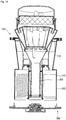
- FIG. 3 is a cross-sectional view of the dust collecting apparatus of FIG. 2
- FIG. 4 is a partial perspective view of a second dust separator according to the embodiment of the present invention
- FIG. 5 is an exploded perspective view of the dust collecting apparatus according to the embodiment of the present invention.
- FIG. 5 is an exploded perspective view of the dust collecting apparatus in which a second dust separator, a filter mechanism and an exhaust cover are omitted.
- the dust collecting apparatus 100 may include a dust collecting body 110.
- the dust collecting body 110 may include a first dust storage 113.
- the dust collecting body 110 may further include a first dust separator 112 having a first inlet port 111.
- the first dust storage 113 may be integrally formed with the first dust separator 112 or may be coupled to the first dust separator 112 by a coupling member.
- the first dust separator 112 may be separately provided from the dust collecting body 110, may be connected with the dust collecting body 110, and may be in communication with the first dust storage 113.
- the first dust separator 112 may be formed in a truncated cone shape, and the first dust storage 113 may be formed in a cylindrical shape. At this time, a diameter of the first dust separator 112 may be gradually reduced downward, and a lower diameter of the first dust separator 112 may be smaller than an upper diameter of the first dust storage 113.
- the first dust separator 112 may be formed in the cylindrical shape.
- the shapes of the first dust separator 112 and the first dust storage 113 are not limited.
- the first dust separator 112 may separate dust from the air using a cyclone principle.
- the dust collecting apparatus 100 may further include a filter part 120 which filters the air separated from the dust in the first dust separator 112.
- the filter part 120 may include a filter body 121.
- the filter body 121 may include one or more holes 122 through which the air passes.
- the filter body 121 may support a second dust separator 130 which will be described below.
- a support rib 123 which supports the second dust separator 130 may be provided at an upper side of the filter body 121.
- a rounded support groove 124 may be provided at the support rib 123.
- the dust collecting apparatus 100 may further include the second dust separator 130 which suctions the air primarily separated from the dust by the first dust separator 112 and separates once more the dust from the suctioned air.
- a part of the second dust separator 130 may be located at an inside of the dust collecting body 110, and another part thereof may be located at an outside of the dust collecting body 110.
- the second dust separator 130 may include a plurality of cyclone parts.
- the plurality of cyclone parts may include a plurality of first cyclone parts 131, and one or more second cyclone parts 133 which is located within an area formed by the plurality of first cyclone parts 131.
- Cyclone flow axes of the plurality of first cyclone parts 131 may be disposed not to be in parallel with cyclone flow axes of the one or more second cyclone parts 133.
- the cyclone flow axes of the second cyclone parts 133 may be disposed in parallel with a vertical line, and each of the cyclone flow axes of the plurality of first cyclone parts 131 may be disposed to be inclined with respect to the vertical line.
- the plurality of first cyclone parts 131 may be disposed in a ring shape. Since the plurality of first cyclone parts 131 are disposed in the ring shape, the one or more second cyclone parts 133 may be located within the area formed by the plurality of first cyclone parts 131.
- the one or more second cyclone parts 133 are located at the area among the plurality of first cyclone parts 131, the number of cyclone parts may be increased, an amount of the air flowing through the second dust separator 130 may be increased, and thus dust separation performance in the second dust separator 130 may be enhanced.
- the fact that an amount of the flowing air is large means that the air may smoothly flow, and when the air flows smoothly, air-dust separation performance in each cyclone part may be enhanced.
- the one or more second cyclone parts 133 are located at the area among the plurality of first cyclone parts 131, a size of the second dust separator 130 is prevented from being increased, even though the number of cyclone parts is increased, and thus the second dust separator 130 may have a compact structure.
- Each of the cyclone parts 131 and 133 may include a second inlet port 132 through which the air is suctioned.
- the air passed through the filter part 120 may be divided and flow into the second inlet port 132 of each of the cyclone parts 131 and 133. That is, the plurality of cyclone parts 131 and 133 may be disposed in parallel.
- Each of the first cyclone parts 131 may be seated in the support groove 124 of the support rib 123 of the filter body 121. A part of each of the cyclone parts 131 and 133 may be accommodated in the filter body 121.
- the second dust separator 130 may further include a supporter 136 which supports a filter mechanism 170.
- the supporter 136 may have an air guide 137 which is inserted into each of the cyclone parts 131 and 133 and guides a discharge of the air separated from the dust.
- the second dust separator 130 may further include a dust discharge guide 138 which guides a discharge of the dust separated from the air in each of the cyclone parts 131 and 133.
- the dust discharged from each of the cyclone parts 131 and 133 may fall down through the dust discharge guide 138.
- the dust collecting apparatus 100 may further include the filter mechanism 170 which filters the air discharged from the second dust separator 130.
- the filter mechanism 170 may include a filter frame 172, and a filter 174 which is accommodated in the filter frame 172.
- the filter frame 172 may be seated at the second dust separator 130.
- the filter frame 172 may be seated at the supporter 136.
- the dust collecting apparatus 100 may further include an exhaust cover 180.
- the exhaust cover 180 may be seated on the second dust separator 130.
- the exhaust cover 180 may cover the filter mechanism 170, while being seated on the second dust separator 130.
- the exhaust cover 180 may include an air discharge port 182 through which the air is discharged.
- the air discharged from the air discharge port 182 may be introduced into the cleaner body 10.
- the exhaust cover 180 may have a fastening part 184 which is fastened to the second dust separator 130.
- the exhaust cover 180 may be fastened to the supporter 136 of the second dust separator 130.
- the dust collecting apparatus 100 may further include a second dust storage 150 which stores the dust separated in the second dust separator 130.
- At least a part of the second dust storage 150 may be located within the first dust storage 113.
- the second dust storage 150 may be connected to a lower side of the second dust separator 130.
- the dust discharge guide 138 of the second dust separator 130 may be seated on the second dust storage 150.
- a part of the second dust storage 150 may be located within the filter part 120.
- a part of the second dust storage 150 may be located within the filter body 121.
- the second dust storage 150 may be located within the filter body 121, and may include a dust introduction guide 151 which is connected with the dust discharge guide 138 and guides an introduction of the dust, and a storage body 152 which extends downward from the dust introduction guide 151 and forms a space for storing the dust.
- the storage body 152 may be formed in a cylindrical shape
- the dust introduction guide 151 may be formed in a cylindrical shape or a truncated cone shape.
- a seating part 153 at which the second dust separator 130 is seated may be provided at the dust introduction guide 151.
- the dust introduction guide 151 may have a fastening part 154 which is fastened to the second dust separator 130.
- the dust collecting apparatus 100 may further include a compressing unit which compresses the dust stored in the first dust storage 113.
- the compressing unit may include a pressing member 200 which is rotatably disposed in the first dust storage 113.
- the compressing unit may further include a fixed member 250 of which a position is fixed in the first dust storage 113.
- the fixed member 250 may be omitted according to a type of the first dust storage 113. In this case, a part of the first dust storage 113 may serve as the fixed member.
- the pressing member 200 may be rotatably connected to the second dust storage 150.
- the fixed member 250 may be integrally formed with the first dust storage 113, or may be coupled to an inner circumferential surface of the first dust storage 113 so that the position thereof is fixed.
- the pressing member 200 may be rotated in one direction or two directions within the first dust storage 113. While the pressing member 200 is rotated, the dust between the pressing member 200 and the fixed member 250 may be compressed.
- the pressing member 200 may include a pressing plate support part 210 having a hollow portion 211, and a pressing plate 220 which is supported by the pressing plate support part 210.
- the pressing plate 220 may be integrally formed with the pressing plate support part 210, or may be coupled to the pressing plate support part 210.
- the pressing plate 220 may extend radially from the pressing plate support part 210.
- a part or the whole of the second dust storage 150 may be located at an inside of the pressing member 200.
- a part or the whole of the second dust storage 150 may be located in the hollow portion 211 of the pressing plate support part 210.
- an outer diameter of the second dust storage 150 may be the same as or smaller than an inner diameter of the pressing plate support part 210.
- FIG. 3 illustrates an example in which the outer diameter of the second dust storage 150 is smaller than the inner diameter of the pressing plate support part 210.
- the pressing plate support part 210 may be prevented from interfering with the second dust storage 150.
- the second dust storage 150 is located in the hollow portion 211 of the pressing plate support part 210, the dust may be stored in the second dust storage 150, and also a volume or a size of the dust collecting apparatus 100 may be prevented from being increased due to the second dust storage 150.
- the pressing plate 220 may include one or more holes 222 through which the air between the pressing plate 220 and the fixed member 250 passes while the pressing member 200 is rotated toward the fixed member 250.
- the dust Since the air remaining in the first dust storage 113 may pass through the one or more holes 222 while the dust is compressed, the dust may be prevented from being scattered due to rising of the air in the first dust storage 113, and may also be prevented from flowing back toward the first dust separator 112.
- the dust collecting apparatus 100 may further include a cover assembly 300 which simultaneously opens and closes the first dust storage 113 and the second dust storage 150.
- the cover assembly 300 may include a first cover 310 which opens and closes the first dust storage 113.
- the first cover 310 may be connected to a lower side of the dust collecting body 110. At this time, the first cover 310 may be separably connected to the lower side of the dust collecting body 110, or may be rotatably connected to the lower side of the dust collecting body 110 by a hinge.
- the first cover 310 may include a first coupling rib 311 and a second coupling rib 312 for coupling with the dust collecting body 110.
- Each of the first coupling rib 311 and the second coupling rib 312 may extend upward from an upper surface of the first cover 310, and may be formed in a circular ring shape.
- the first coupling rib 311 and the second coupling rib 312 may be spaced apart from each other.
- the lower side of the dust collecting body 110 may be inserted between the first coupling rib 311 and the second coupling rib 312.
- the cover assembly 300 may further a transmission mechanism which transmits power from an outside to the pressing member 200.
- the transmission mechanism may include a first transmission part 330 and a second transmission part 340.
- the first transmission part 330 may be disposed at one side of the first cover 310, and the second transmission part 340 may be disposed at the other side of the first cover 310.
- at least a part of the first transmission part 330 is disposed at a lower side of the first cover 310, and at least a part of the second transmission part 340 may be disposed at an upper side of the first cover 310.
- the first transmission part 330 may be connected with a driving unit which will be described.
- the second transmission part 340 may be connected with the pressing member 200.
- the first cover 310 may have an opening 314 through which one or more of the first transmission part 330 and the second transmission part 340 pass.
- the cover assembly 300 may further include a transmission part cover 320 which covers the first transmission part 330.
- the transmission part cover 320 may be fastened to the first cover 310.
- a first fastening hole 315 may be formed at the first cover 310
- a second fastening hole 325 may be formed at the transmission part cover 320.
- the transmission part cover 320 may be fastened to the lower side of the first cover 310.
- the transmission part cover 320 may include a support part 322 which supports the first transmission part 330.
- the support part 322 may be formed by recessing a part of the transmission part cover 320 downward.
- a shaft 326 which passes through the first transmission part 330 may be provided at the support part 322.
- the shaft 326 may be integrally formed with the support part 322 or may be coupled to the support part 322.
- the first transmission part 330 may be rotated about the shaft 326.
- the shaft 326 may also pass through the second transmission part 340.
- the transmission part cover 320 may further include an exposure part 324 through which the first transmission part 330 is exposed to an outside.
- the exposure part 324 may be a cut-away part which is formed by cutting away a part of the first transmission part 330.
- the cover assembly 300 may further include a second cover 350 which opens and closes the second dust storage 150. While the second dust storage 150 is closed by the second cover 350, the second cover 350 may be located within the pressing plate support part 210 of the pressing member 200.
- the pressing plate support part 210 When the second cover 350 is located within the pressing plate support part 210, interference between the pressing plate support part 210 and the second cover 350 may be prevented, and the pressing plate support part 210 may serve as a sealing wall.
- a sealing member 360 may be coupled to the second cover 350 or the second dust storage 150.
- FIG. 3 illustrates an example in which the sealing member 360 is coupled to the second dust storage 150.
- FIG. 6 is an enlarged view of a portion A of FIG. 3 .
- a hole 125 through which the second dust storage 150 passes may be formed at the filter part 120.
- An accommodation groove 127 in which an upper end of the pressing plate support part 210 of the pressing member 200 is inserted may be formed at a lower side of the filter part 120.
- a wall supporter 214 having an accommodation groove 213 for accommodation a wall 128 which forms the accommodation groove 127 while the pressing plate support part 210 is accommodated in the accommodation groove 127 may be provided at the pressing plate support part 210.
- the upper end of the pressing plate support part 210 is inserted into the accommodation groove 127 of the filter part 120, and the wall 128 which extends from the filter part 120 is inserted into the accommodation groove 213 of the wall supporter 214 of the pressing plate support part 210, a dual sealing structure is formed, and thus the dust in the first dust storage 113 may be prevented from being introduced between the pressing plate support part 210 and the second dust storage 150.
- the accommodation grooves 127 and 213, the wall 128 and the wall supporter 214 may be referred to as a sealing mechanism.
- a coupling protrusion 212 may be formed at one of an inner circumferential surface of the pressing plate support part 210 and an outer circumferential surface of the second dust storage 150, and a coupling groove 156 in which the coupling protrusion 212 is inserted may be formed at the other one.
- the coupling protrusion 212 may be elastically deformed, while the second dust storage 150 is inserted into the pressing plate support part 210, and then may be inserted into the coupling groove 156, when being aligned with the coupling groove 156.
- a coupling pin which is separately formed from the pressing plate support part 210 and the second dust storage 150 may pass through the pressing plate support part 210 from an outside of the pressing plate support part 210, and may be inserted into the coupling groove 156 formed at the second dust storage 150.
- the coupling pin which is separately formed from the pressing plate support part 210 and the second dust storage 150 may pass through the second dust storage 150 from an inside of the second dust storage 150, and may be inserted into the coupling groove 156.
- the coupling groove 156 is formed in a ring shape in a radial direction of the pressing plate support part 210 or the second dust storage 150.
- the pressing plate support part 210 is maintained in a coupled state with the second dust storage 150 while the cover assembly 300 is separated from the dust collecting body 110, the pressing member 200 is maintained in a located state in the first dust storage 113. That is, while the cover assembly 300 is separated from the dust collecting body 110, the pressing member 200 may be prevented from being separated from the dust collecting body 110.
- a blocking part 129 which prevents the dust and air in the first dust storage 113 from raising may be provided at the lower side of the filter part 120.
- FIG. 7 is an enlarged view of a portion B of FIG. 3 .
- the sealing member 360 may be coupled to the lower side of the second dust storage 150.
- the sealing member 360 may include a coupling part 361 for coupling with the second dust storage 150, and a groove 158 in which a part of the coupling part 361 is inserted may be formed at the outer circumferential surface of the second dust storage 150. That is, the sealing member 360 may cover a circumference of the second dust storage 150.
- the coupling part 351 may be fitted into the second dust storage 150.
- the sealing member 360 may include a seating part 362 which is seated on the second cover 350 while the cover assembly 300 is coupled to the dust collecting body 110.
- the seating part 362 is in surface contact with the second cover 350, and may cover an outer circumference of the second cover 350. In other words, a part of the second cover 350 may be inserted into the sealing member 360.
- a through-hole 363 through which the dust in the second dust storage 150 passes may be formed at the sealing member 360. Therefore, some of the dust in the second dust storage 150 may be accumulated on the second cover 350.
- the sealing member may be formed of a deformable material.
- the sealing member 360 may be formed of a rubber material.
- the sealing member 360 since the sealing member 360 is in surface contact with the second cover 350 and covers the circumference of the second cover 350, the dust stored in the second dust storage 150 may be prevented from leaking to the outside of the second dust storage 150.
- the first transmission part 330 may include an insertion part 332 which is inserted into the second transmission part 340, and the second transmission part 340 may include an accommodation part 343 in which the insertion part 332 is inserted.
- a fastening groove 333 in which a fastening member S1 passed through a fastening hole 344 of the second transmission part 340 is fastened may be formed at the insertion part 332.
- the second transmission part 340 may also be rotated.
- one of the pressing plate support part 210 and the second transmission part 340 may include a transmission protrusion 216, and the other one may include an accommodation groove 342 in which the transmission protrusion 216 is accommodated.
- FIG. 7 illustrates an example in which the transmission protrusion 216 is formed at the pressing plate support part 210, and the accommodation groove 342 is formed at the second transmission part 340.
- the transmission protrusion 216 may protrude from the outer circumferential surface of the pressing plate support part 210.
- a part of the second transmission part 340 may be inserted into the pressing plate support part 210.
- the transmission protrusion 216 may protrude downward from a lower surface of the pressing plate support part 210. In this case, while a part of the second transmission part 340 is not accommodated in the pressing plate support part 210, the transmission protrusion 216 may be accommodated in the accommodation groove 342 of the second transmission part 340.
- the second cover 350 may be fastened to the shaft 326 of the transmission part cover 320 by a fastening member S2. Therefore, even though the first transmission part 330 and the second transmission part 340 are rotated, the second cover 350 may be maintained in a stopped state.
- a first sealing part 371 may be provided at one or more of the first transmission part 330 and the first cover 310.
- the first sealing part 371 may be an O-ring.
- FIG. 7 illustrates an example in which the first sealing part 371 is provided at the first transmission part 330.
- a first groove 338 which accommodates the first sealing part 371 may be provided at the first transmission part 330.
- a second sealing part 372 may be provided at a portion in which the second cover 350 and the second transmission part 340 face each other.
- the second sealing part 372 may be an O-ring.
- the second sealing part 372 may prevent the air and the dust in the first dust storage 113 from passing through a gap between the second cover 350 and the second transmission part 340.
- the second sealing part 372 may prevent the dust and air, which may be located between the second dust storage 150 and the pressing plate support part 210, from passing through the gap between the second cover 350 and the second transmission part 340.
- FIG. 8 is a view illustrating a state in which the dust collecting apparatus is separated from the vacuum cleaner of FIG. 1 .
- the cleaner body 10 may include driving units 410 and420 which drive the pressing member 200.
- the driving units 410 and 420 may include a driving motor 410, and a driving gear 420 which is connected with the driving motor 410.
- the cleaner body 10 has an installation part 13 at which the dust collecting apparatus 100 is installed, and the driving gear 420 may be exposed to the installation part 13.
- the driving gear 420 may transmit power of the driving motor 410 to the first transmission part 330.
- the first transmission part 330 may be a gear.
- the first transmission part 330 When the dust collecting apparatus 100 is installed at the installation part 13 of the cleaner body 10, the first transmission part 330 may be connected with the driving gear 420. However, when the dust collecting apparatus 100 is separated from the cleaner body 10, connection between the first transmission part 330 and the driving gear 420 may be released.
- FIG. 9 is a view illustrating a state in which the air and the dust are moved in the dust collecting apparatus according to the embodiment of the present invention.
- the suction motor provided at the cleaner body 10 when the suction motor provided at the cleaner body 10 is operated, the air and the dust are suctioned through the suction nozzle 20 by a suction force of the suction motor.
- the air and the dust suctioned through the suction nozzle 20 pass through the supporter 30, and then are introduced into the cleaner body 10.
- the dust and air flowing through the cleaner body 10 are introduced into the dust collecting apparatus 100.
- the dust and air are introduced into the dust collecting apparatus 100 through the first inlet port 111 of the dust collecting apparatus 100.
- the dust and air passed through the first inlet port 111 are introduced into the first dust separator 112.
- the dust and air introduced into the first dust separator 112 are separated from each other by a cyclone flow.
- the dust which is primarily separated from the air is moved downward and stored in the first dust storage 113. However, the air separated from the dust passes through the hole 122 of the filter part 120, is then moved upward, and introduced into the second dust separator 130 through the second inlet port 132 of the second dust separator 130. That is, the air which is separated from the dust in the first dust separator 112 is divided into and flows through the plurality of first cyclone parts 131 and the one or more second cyclone parts 133.
- the air introduced into the second dust separator 130 is separated once more from the dust during the cyclone flow.
- the dust (referring to a dotted line) separated from the air in the second dust separator 130 is discharged from the second dust separator 130 and then stored in the second dust storage 150.
- the air separated from the dust in the second dust separator 130 is discharged from each of the cyclone parts 131 and 133 through the air guide 137.
- the air discharged from each of the cyclone parts 131 and 133 passes through the filter 174, and is lastly discharged from the dust collecting apparatus 100 through the air discharge port 182 of the exhaust cover 180.
- the air discharged from the dust collecting apparatus 100 may be introduced into the cleaner body 10, and then may be discharged from the cleaner body 10 to the outside.
- the driving motor 410 is operated.
- the driving gear 420 may be rotated in one direction.
- the driving gear 420 is rotated in one direction, the first transmission part 330 may be rotated in the other direction by the rotational force of the driving gear 420.
- the second transmission part 340 is rotated in the same direction as that of the first transmission part 330, and the pressing member 200 may be rotated in the same direction as that of the second transmission part 340.
- the dust (in the first dust storage) between the fixed member 250 and the pressing plate 220 of the pressing member 200 may be compressed.
- the dust stored in the first dust storage 113 since the dust stored in the first dust storage 113 may be compressed, a volume of the dust stored in the first dust storage 113 is reduced, and thus a dust storage capacity of the first dust storage 113 may be increased. Since the dust in a compressed state is stored in the first dust storage, the dust may be prevented from being scattered while the dust is discharged.
- a rotational direction of the pressing member 200 may be varied.
- a method of changing the rotational direction of the pressing member 200 may be realized by a well-known technique, and thus detailed description thereof will be omitted.
- FIG. 10 is a view illustrating a state in which the cover assembly is separated from the dust collecting apparatus according to the embodiment of the present invention.
- the cover assembly 300 may be separated from the dust collecting apparatus 100.
- the dust stored in the first dust storage 113 and the second dust storage 150 may fall down from the dust collecting body 110.
- the pressing member 200 is maintained in the first dust storage 113.
Landscapes
- Engineering & Computer Science (AREA)
- Mechanical Engineering (AREA)
- Chemical & Material Sciences (AREA)
- Chemical Kinetics & Catalysis (AREA)
- Filters For Electric Vacuum Cleaners (AREA)
- Refuse Collection And Transfer (AREA)
Claims (15)
- Appareil de collecte de poussière comprenant :un premier séparateur de poussière (110) configuré pour séparer principalement une première portion de poussière, de l'air aspiré ;un premier stockage de poussière (113) configuré pour stocker la première portion de poussière séparée dans le premier séparateur de poussière (110) ;un organe de pressage (200) configuré pour compresser la première portion de poussière stockée dans le premier stockage de poussière (113), et présentant une partie de support de plaque de pressage (210) et une plaque de pressage (220) supportée par la partie de support de plaque de pressage (210) ;un second séparateur de poussière (130) configuré pour séparer encore une seconde portion de poussière de l'air passé par un processus de séparation de poussière dans le premier séparateur de poussière (110) ; etun second stockage de poussière (150) configuré pour stocker la seconde portion de poussière séparée dans le second séparateur de poussière (130), caractérisé en ce que le second stockage de poussière est situé en une partie intérieure de la partie de support de plaque de pressage (210).
- Appareil selon la revendication 1, dans lequel la partie de support de plaque de pressage (210) est disposée de manière à pouvoir tourner dans le premier stockage de poussière (113).
- Appareil selon la revendication 1 ou 2, dans lequel la partie de support de plaque de pressage (210) est reliée au second stockage de poussière (150).
- Appareil selon la revendication 3, dans lequel une saillie de couplage (212) est prévue en une surface parmi une surface circonférentielle intérieure de la partie de support de plaque de pressage (210) et une surface circonférentielle extérieure du second stockage de poussière (150), et une rainure de couplage (156), dans laquelle la saillie de couplage (212) est couplée, est prévue en l'autre surface.
- Appareil selon l'une quelconque des revendications 1 à 4, comprenant en outre une partie de filtre (120) configurée pour filtrer l'air séparé dans le premier séparateur de poussière (110),
dans lequel une partie du second stockage de poussière est située dans la partie de filtre. - Appareil selon l'une quelconque des revendications 1 à 5, comprenant en outre un mécanisme d'étanchéité configuré pour empêcher l'air et la poussière d'être introduits entre la partie de support de plaque de pressage (210) et le second stockage de poussière (150).
- Appareil selon l'une quelconque des revendications 1 à 5, comprenant en outre un ensemble de couvercle (300) configuré pour ouvrir et fermer le premier stockage de poussière (113) et le second stockage de poussière (150).
- Appareil selon la revendication 7, dans lequel l'ensemble de couvercle (300) comprend un premier couvercle (310) configuré pour ouvrir et fermer le premier stockage de poussière (113) et un second couvercle (350) configuré pour ouvrir et fermer le second stockage de poussière (150).
- Appareil selon la revendication 8, dans lequel, tandis que le premier couvercle (310) ferme le premier stockage de poussière (113), le second couvercle (350) est situé dans la partie de support de plaque de pressage (210).
- Appareil selon la revendication 8 ou 9, dans lequel un organe d'étanchéité (360) est couplé à l'un parmi le second stockage de poussière (150) et le second couvercle (350), et dans lequel l'organe d'étanchéité (360) est configuré pour empêcher la poussière stockée dans le second stockage de poussière (150) de fuir vers un extérieur du second stockage de poussière (150).
- Appareil selon l'une quelconque des revendications 7 à 10, dans lequel l'ensemble de couvercle (300) comprend en outre un mécanisme de transmission configuré pour transmettre une puissance externe à l'organe de pressage (200), et le mécanisme de transmission est relié à la partie de support de plaque de pressage (210) de l'organe de pressage (200).
- Appareil selon l'une quelconque des revendications 8 à 11, dans lequel l'ensemble de couvercle (300) comprend en outre une partie d'étanchéité (371) configurée pour empêcher l'air et la poussière dans le premier stockage de poussière (113) de fuir entre le mécanisme de transmission et le premier couvercle (310).
- Appareil selon l'une quelconque des revendications 8 à 12, dans lequel l'ensemble de couvercle (300) comprend en outre une partie d'étanchéité (372) configurée pour empêcher l'air et la poussière entre la partie de support de plaque de pressage (210) et le second stockage de poussière (150) de fuir entre le mécanisme de transmission et le second couvercle (350).
- Appareil selon la revendication 11, dans lequel l'ensemble de couvercle (300) comprend en outre un couvercle de partie de transmission (320) présentant un arbre (326) configuré pour supporter de manière rotative le mécanisme de transmission, dans lequel le mécanisme de transmission comprend une première partie de transmission (330) reliée en rotation à l'arbre (326), et une seconde partie de transmission (340) couplée à la première partie de transmission (330) et reliée à la partie de support de plaque de pressage (210).
- Appareil selon l'une quelconque des revendications 1 à 14, dans lequel le second séparateur de poussière (130) comprend une pluralité de premières parties de cyclone (131), et une ou plusieurs secondes parties de cyclone (133) situées dans une zone formée par la pluralité de premières parties de cyclone (131).
Applications Claiming Priority (1)
| Application Number | Priority Date | Filing Date | Title |
|---|---|---|---|
| KR1020140169814A KR101653459B1 (ko) | 2014-12-01 | 2014-12-01 | 진공 청소기 및 집진장치 |
Publications (2)
| Publication Number | Publication Date |
|---|---|
| EP3028620A1 EP3028620A1 (fr) | 2016-06-08 |
| EP3028620B1 true EP3028620B1 (fr) | 2017-08-23 |
Family
ID=54770948
Family Applications (1)
| Application Number | Title | Priority Date | Filing Date |
|---|---|---|---|
| EP15197300.5A Active EP3028620B1 (fr) | 2014-12-01 | 2015-12-01 | Aspirateur et appareil de collecte de poussière |
Country Status (5)
| Country | Link |
|---|---|
| US (1) | US10130226B2 (fr) |
| EP (1) | EP3028620B1 (fr) |
| KR (1) | KR101653459B1 (fr) |
| CN (1) | CN105640433B (fr) |
| ES (1) | ES2643050T3 (fr) |
Families Citing this family (14)
| Publication number | Priority date | Publication date | Assignee | Title |
|---|---|---|---|---|
| US20140237768A1 (en) | 2013-02-28 | 2014-08-28 | G.B.D. Corp. | Surface cleaning apparatus |
| KR101653459B1 (ko) * | 2014-12-01 | 2016-09-01 | 엘지전자 주식회사 | 진공 청소기 및 집진장치 |
| KR102202268B1 (ko) * | 2014-12-17 | 2021-01-13 | 엘지전자 주식회사 | 진공 청소기용 집진장치 |
| KR101653481B1 (ko) * | 2015-01-16 | 2016-09-01 | 엘지전자 주식회사 | 진공 청소기 및 집진장치 |
| KR102319174B1 (ko) * | 2015-01-19 | 2021-10-29 | 엘지전자 주식회사 | 진공 청소기용 집진장치 |
| KR102306705B1 (ko) * | 2016-08-25 | 2021-09-30 | 엘지전자 주식회사 | 청소기 |
| US10722832B1 (en) * | 2017-01-27 | 2020-07-28 | James Hardie Technology Limited | Dust removal system |
| GB2561598B (en) * | 2017-04-20 | 2022-10-05 | Techtronic Floor Care Tech Ltd | Suction cleaner |
| CN212261266U (zh) * | 2017-07-05 | 2021-01-01 | 创科(澳门离岸商业服务)有限公司 | 真空吸尘器 |
| CN108209723B (zh) * | 2018-03-01 | 2021-04-16 | 江苏美的清洁电器股份有限公司 | 旋风分离装置和具有其的吸尘器 |
| FR3085829B1 (fr) * | 2018-09-18 | 2020-10-23 | Seb Sa | Dispositif de separation cyclonique pour aspirateur domestique |
| KR102699769B1 (ko) * | 2019-06-05 | 2024-08-29 | 엘지전자 주식회사 | 청소기 |
| CN112741530B (zh) * | 2019-10-31 | 2023-05-12 | 江苏美的清洁电器股份有限公司 | 吸尘器 |
| CN110693391B (zh) * | 2019-11-27 | 2025-02-18 | 珠海格力电器股份有限公司 | 吸尘器、旋风分离机构及安装支架 |
Family Cites Families (47)
| Publication number | Priority date | Publication date | Assignee | Title |
|---|---|---|---|---|
| US2553175A (en) * | 1949-02-01 | 1951-05-15 | Beaumont Birch Company | Apparatus for collecting ash and dust |
| DK174814B1 (da) * | 1998-02-25 | 2003-12-01 | Cook William Europ | Stentaggregat |
| AU2002225207B2 (en) * | 2001-02-24 | 2004-12-09 | Dyson Technology Limited | A collecting chamber for a vacuum cleaner |
| US7779506B2 (en) * | 2004-03-11 | 2010-08-24 | Lg Electronics Inc. | Vacuum cleaner |
| US7547336B2 (en) * | 2004-12-13 | 2009-06-16 | Bissell Homecare, Inc. | Vacuum cleaner with multiple cyclonic dirt separators and bottom discharge dirt cup |
| GB2426473B (en) * | 2005-05-27 | 2008-11-05 | Dyson Technology Ltd | Cyclonic separating apparatus |
| US8978197B2 (en) * | 2009-03-13 | 2015-03-17 | Lg Electronics Inc. | Vacuum cleaner |
| US8404034B2 (en) * | 2005-12-10 | 2013-03-26 | Lg Electronics Inc. | Vacuum cleaner and method of controlling the same |
| US8544143B2 (en) * | 2005-12-10 | 2013-10-01 | Lg Electronics Inc. | Vacuum cleaner with removable dust collector, and methods of operating the same |
| US7987551B2 (en) * | 2005-12-10 | 2011-08-02 | Lg Electronics Inc. | Vacuum cleaner |
| US8012250B2 (en) * | 2005-12-10 | 2011-09-06 | Lg Electronics Inc. | Vacuum cleaner |
| US7882592B2 (en) | 2005-12-10 | 2011-02-08 | Lg Electronics Inc. | Vacuum cleaner |
| US8281455B2 (en) * | 2005-12-10 | 2012-10-09 | Lg Electronics Inc. | Vacuum cleaner |
| US7749295B2 (en) * | 2005-12-10 | 2010-07-06 | Lg Electronics Inc. | Vacuum cleaner with removable dust collector, and methods of operating the same |
| KR100871483B1 (ko) * | 2006-02-24 | 2008-12-05 | 엘지전자 주식회사 | 집진장치 및 이를 가지는 진공 청소기 |
| US20100005617A1 (en) * | 2006-10-31 | 2010-01-14 | Hyun Kie-Tak | Vacuum cleaner |
| EP1949842B1 (fr) * | 2007-01-24 | 2015-03-04 | LG Electronics Inc. | Aspirateur |
| KR100783143B1 (ko) * | 2007-02-05 | 2007-12-07 | 삼성광주전자 주식회사 | 진공청소기용 사이클론 집진장치 |
| KR101309780B1 (ko) * | 2007-04-17 | 2013-09-23 | 삼성전자주식회사 | 진공청소기의 사이클론 집진장치 |
| JP4904226B2 (ja) * | 2007-08-30 | 2012-03-28 | シャープ株式会社 | サイクロン集塵装置,電気掃除機 |
| GB2453761B (en) * | 2007-10-18 | 2012-04-18 | Dyson Technology Ltd | Cyclonic separating apparatus for a cleaning appliance |
| GB2453949B (en) * | 2007-10-23 | 2012-03-28 | Hoover Ltd | Cyclonic separation apparatus |
| US8209815B2 (en) * | 2007-12-06 | 2012-07-03 | Techtronic Floor Care Technology Limited | Dual stage cyclonic dust collector |
| US7691161B2 (en) * | 2008-01-31 | 2010-04-06 | Samsung Gwangju Electronics Co., Ltd. | Cyclone dust-collecting apparatus |
| KR100941429B1 (ko) * | 2008-02-19 | 2010-02-11 | 엘지전자 주식회사 | 진공 청소기 |
| JP5075738B2 (ja) * | 2008-05-30 | 2012-11-21 | 日立アプライアンス株式会社 | 電気掃除機 |
| KR100996531B1 (ko) * | 2008-07-02 | 2010-11-24 | 엘지전자 주식회사 | 진공 청소기 |
| US8881343B2 (en) * | 2009-02-12 | 2014-11-11 | Lg Electronics Inc. | Vacuum cleaner |
| KR20110048511A (ko) | 2009-02-12 | 2011-05-11 | 엘지전자 주식회사 | 진공 청소기 |
| US8151409B2 (en) * | 2009-02-26 | 2012-04-10 | Lg Electronics Inc. | Vacuum cleaner |
| US8713752B2 (en) * | 2009-03-13 | 2014-05-06 | Lg Electronics Inc. | Vacuum cleaner |
| KR20100108839A (ko) | 2009-03-30 | 2010-10-08 | 삼성광주전자 주식회사 | 먼지 압축식 집진장치 |
| US8887349B2 (en) * | 2009-04-16 | 2014-11-18 | Lg Electronics Inc. | Vacuum cleaner |
| US8474092B2 (en) * | 2009-11-01 | 2013-07-02 | Lg Electronics Inc. | Vacuum cleaner |
| US8370992B2 (en) * | 2009-11-01 | 2013-02-12 | Lg Electronics Inc. | Vacuum cleaner |
| EP2420173B1 (fr) * | 2009-11-03 | 2016-01-27 | LG Electronics Inc. | Aspirateur |
| WO2011055861A1 (fr) * | 2009-11-03 | 2011-05-12 | 엘지전자 주식회사 | Aspirateur |
| US9003601B2 (en) * | 2009-11-04 | 2015-04-14 | Lg Electronics Inc. | Vacuum cleaner |
| GB2490696B (en) * | 2011-05-11 | 2014-12-17 | Dyson Technology Ltd | A cyclonic surface treating appliance with multiple cyclones |
| US8679211B1 (en) * | 2013-02-11 | 2014-03-25 | Techtronic Floor Care Technology Limited | Cyclonic separator assembly for a vacuum cleaner |
| KR101520547B1 (ko) * | 2013-10-18 | 2015-05-14 | 엘지전자 주식회사 | 진공 청소기 |
| JP5735153B2 (ja) * | 2014-03-20 | 2015-06-17 | シャープ株式会社 | 集塵装置、および電気掃除機 |
| KR101622724B1 (ko) * | 2014-09-29 | 2016-05-19 | 엘지전자 주식회사 | 진공청소기용 집진장치 |
| KR101622726B1 (ko) * | 2014-09-30 | 2016-05-19 | 엘지전자 주식회사 | 집진장치 및 이를 구비하는 진공 청소기 |
| KR101641261B1 (ko) * | 2014-10-28 | 2016-07-20 | 엘지전자 주식회사 | 청소기 |
| KR101641262B1 (ko) * | 2014-12-01 | 2016-07-20 | 엘지전자 주식회사 | 로봇 청소기 |
| KR101653459B1 (ko) * | 2014-12-01 | 2016-09-01 | 엘지전자 주식회사 | 진공 청소기 및 집진장치 |
-
2014
- 2014-12-01 KR KR1020140169814A patent/KR101653459B1/ko not_active Expired - Fee Related
-
2015
- 2015-11-27 CN CN201510848563.0A patent/CN105640433B/zh active Active
- 2015-12-01 US US14/955,478 patent/US10130226B2/en active Active
- 2015-12-01 ES ES15197300.5T patent/ES2643050T3/es active Active
- 2015-12-01 EP EP15197300.5A patent/EP3028620B1/fr active Active
Non-Patent Citations (1)
| Title |
|---|
| None * |
Also Published As
| Publication number | Publication date |
|---|---|
| CN105640433A (zh) | 2016-06-08 |
| CN105640433B (zh) | 2018-08-10 |
| KR101653459B1 (ko) | 2016-09-01 |
| ES2643050T3 (es) | 2017-11-21 |
| US20160150929A1 (en) | 2016-06-02 |
| EP3028620A1 (fr) | 2016-06-08 |
| KR20160065610A (ko) | 2016-06-09 |
| US10130226B2 (en) | 2018-11-20 |
Similar Documents
| Publication | Publication Date | Title |
|---|---|---|
| EP3028620A1 (fr) | Aspirateur et appareil de collecte de poussière | |
| US10750914B2 (en) | Dust collecting apparatus | |
| EP2862489B1 (fr) | Aspirateur | |
| US7635400B2 (en) | Dust collecting device for vacuum cleaner | |
| US10925452B2 (en) | Dust collector for vacuum cleaner | |
| US10898045B2 (en) | Dust collecting apparatus for vacuum cleaner and vacuum cleaner including same | |
| EP3998006B1 (fr) | Aspirateur | |
| KR101487622B1 (ko) | 진공 청소기 | |
| WO2007145414A1 (fr) | Appareil de collecte de poussière pour aspirateur | |
| KR102073618B1 (ko) | 청소기 | |
| CN111655104B (zh) | 清洁器 | |
| KR20120083812A (ko) | 드럼 타입의 진공청소기 및 이의 조립방법 | |
| EP3005924B1 (fr) | Collecteur de poussière pour aspirateur | |
| EP1676514B1 (fr) | Aspirateur | |
| KR20210108133A (ko) | 청소기 | |
| KR102344069B1 (ko) | 청소기 | |
| KR100854147B1 (ko) | 진공 청소기의 먼지 분리 장치 |
Legal Events
| Date | Code | Title | Description |
|---|---|---|---|
| PUAI | Public reference made under article 153(3) epc to a published international application that has entered the european phase |
Free format text: ORIGINAL CODE: 0009012 |
|
| 17P | Request for examination filed |
Effective date: 20160101 |
|
| AK | Designated contracting states |
Kind code of ref document: A1 Designated state(s): AL AT BE BG CH CY CZ DE DK EE ES FI FR GB GR HR HU IE IS IT LI LT LU LV MC MK MT NL NO PL PT RO RS SE SI SK SM TR |
|
| AX | Request for extension of the european patent |
Extension state: BA ME |
|
| RBV | Designated contracting states (corrected) |
Designated state(s): AL AT BE BG CH CY CZ DE DK EE ES FI FR GB GR HR HU IE IS IT LI LT LU LV MC MK MT NL NO PL PT RO RS SE SI SK SM TR |
|
| GRAP | Despatch of communication of intention to grant a patent |
Free format text: ORIGINAL CODE: EPIDOSNIGR1 |
|
| RIC1 | Information provided on ipc code assigned before grant |
Ipc: A47L 9/16 20060101ALI20170214BHEP Ipc: A47L 9/10 20060101AFI20170214BHEP |
|
| INTG | Intention to grant announced |
Effective date: 20170323 |
|
| GRAS | Grant fee paid |
Free format text: ORIGINAL CODE: EPIDOSNIGR3 |
|
| GRAA | (expected) grant |
Free format text: ORIGINAL CODE: 0009210 |
|
| AK | Designated contracting states |
Kind code of ref document: B1 Designated state(s): AL AT BE BG CH CY CZ DE DK EE ES FI FR GB GR HR HU IE IS IT LI LT LU LV MC MK MT NL NO PL PT RO RS SE SI SK SM TR |
|
| REG | Reference to a national code |
Ref country code: GB Ref legal event code: FG4D |
|
| REG | Reference to a national code |
Ref country code: CH Ref legal event code: EP |
|
| REG | Reference to a national code |
Ref country code: AT Ref legal event code: REF Ref document number: 920386 Country of ref document: AT Kind code of ref document: T Effective date: 20170915 |
|
| REG | Reference to a national code |
Ref country code: IE Ref legal event code: FG4D |
|
| REG | Reference to a national code |
Ref country code: DE Ref legal event code: R096 Ref document number: 602015004299 Country of ref document: DE |
|
| REG | Reference to a national code |
Ref country code: ES Ref legal event code: FG2A Ref document number: 2643050 Country of ref document: ES Kind code of ref document: T3 Effective date: 20171121 |
|
| REG | Reference to a national code |
Ref country code: FR Ref legal event code: PLFP Year of fee payment: 3 |
|
| REG | Reference to a national code |
Ref country code: NL Ref legal event code: MP Effective date: 20170823 |
|
| REG | Reference to a national code |
Ref country code: LT Ref legal event code: MG4D |
|
| REG | Reference to a national code |
Ref country code: AT Ref legal event code: MK05 Ref document number: 920386 Country of ref document: AT Kind code of ref document: T Effective date: 20170823 |
|
| PG25 | Lapsed in a contracting state [announced via postgrant information from national office to epo] |
Ref country code: HR Free format text: LAPSE BECAUSE OF FAILURE TO SUBMIT A TRANSLATION OF THE DESCRIPTION OR TO PAY THE FEE WITHIN THE PRESCRIBED TIME-LIMIT Effective date: 20170823 Ref country code: LT Free format text: LAPSE BECAUSE OF FAILURE TO SUBMIT A TRANSLATION OF THE DESCRIPTION OR TO PAY THE FEE WITHIN THE PRESCRIBED TIME-LIMIT Effective date: 20170823 Ref country code: NL Free format text: LAPSE BECAUSE OF FAILURE TO SUBMIT A TRANSLATION OF THE DESCRIPTION OR TO PAY THE FEE WITHIN THE PRESCRIBED TIME-LIMIT Effective date: 20170823 Ref country code: NO Free format text: LAPSE BECAUSE OF FAILURE TO SUBMIT A TRANSLATION OF THE DESCRIPTION OR TO PAY THE FEE WITHIN THE PRESCRIBED TIME-LIMIT Effective date: 20171123 Ref country code: AT Free format text: LAPSE BECAUSE OF FAILURE TO SUBMIT A TRANSLATION OF THE DESCRIPTION OR TO PAY THE FEE WITHIN THE PRESCRIBED TIME-LIMIT Effective date: 20170823 Ref country code: SE Free format text: LAPSE BECAUSE OF FAILURE TO SUBMIT A TRANSLATION OF THE DESCRIPTION OR TO PAY THE FEE WITHIN THE PRESCRIBED TIME-LIMIT Effective date: 20170823 Ref country code: FI Free format text: LAPSE BECAUSE OF FAILURE TO SUBMIT A TRANSLATION OF THE DESCRIPTION OR TO PAY THE FEE WITHIN THE PRESCRIBED TIME-LIMIT Effective date: 20170823 |
|
| PG25 | Lapsed in a contracting state [announced via postgrant information from national office to epo] |
Ref country code: IS Free format text: LAPSE BECAUSE OF FAILURE TO SUBMIT A TRANSLATION OF THE DESCRIPTION OR TO PAY THE FEE WITHIN THE PRESCRIBED TIME-LIMIT Effective date: 20171223 Ref country code: LV Free format text: LAPSE BECAUSE OF FAILURE TO SUBMIT A TRANSLATION OF THE DESCRIPTION OR TO PAY THE FEE WITHIN THE PRESCRIBED TIME-LIMIT Effective date: 20170823 Ref country code: GR Free format text: LAPSE BECAUSE OF FAILURE TO SUBMIT A TRANSLATION OF THE DESCRIPTION OR TO PAY THE FEE WITHIN THE PRESCRIBED TIME-LIMIT Effective date: 20171124 Ref country code: BG Free format text: LAPSE BECAUSE OF FAILURE TO SUBMIT A TRANSLATION OF THE DESCRIPTION OR TO PAY THE FEE WITHIN THE PRESCRIBED TIME-LIMIT Effective date: 20171123 Ref country code: PL Free format text: LAPSE BECAUSE OF FAILURE TO SUBMIT A TRANSLATION OF THE DESCRIPTION OR TO PAY THE FEE WITHIN THE PRESCRIBED TIME-LIMIT Effective date: 20170823 Ref country code: RS Free format text: LAPSE BECAUSE OF FAILURE TO SUBMIT A TRANSLATION OF THE DESCRIPTION OR TO PAY THE FEE WITHIN THE PRESCRIBED TIME-LIMIT Effective date: 20170823 |
|
| PG25 | Lapsed in a contracting state [announced via postgrant information from national office to epo] |
Ref country code: DK Free format text: LAPSE BECAUSE OF FAILURE TO SUBMIT A TRANSLATION OF THE DESCRIPTION OR TO PAY THE FEE WITHIN THE PRESCRIBED TIME-LIMIT Effective date: 20170823 Ref country code: CZ Free format text: LAPSE BECAUSE OF FAILURE TO SUBMIT A TRANSLATION OF THE DESCRIPTION OR TO PAY THE FEE WITHIN THE PRESCRIBED TIME-LIMIT Effective date: 20170823 Ref country code: RO Free format text: LAPSE BECAUSE OF FAILURE TO SUBMIT A TRANSLATION OF THE DESCRIPTION OR TO PAY THE FEE WITHIN THE PRESCRIBED TIME-LIMIT Effective date: 20170823 |
|
| REG | Reference to a national code |
Ref country code: DE Ref legal event code: R097 Ref document number: 602015004299 Country of ref document: DE |
|
| PG25 | Lapsed in a contracting state [announced via postgrant information from national office to epo] |
Ref country code: EE Free format text: LAPSE BECAUSE OF FAILURE TO SUBMIT A TRANSLATION OF THE DESCRIPTION OR TO PAY THE FEE WITHIN THE PRESCRIBED TIME-LIMIT Effective date: 20170823 Ref country code: SM Free format text: LAPSE BECAUSE OF FAILURE TO SUBMIT A TRANSLATION OF THE DESCRIPTION OR TO PAY THE FEE WITHIN THE PRESCRIBED TIME-LIMIT Effective date: 20170823 Ref country code: SK Free format text: LAPSE BECAUSE OF FAILURE TO SUBMIT A TRANSLATION OF THE DESCRIPTION OR TO PAY THE FEE WITHIN THE PRESCRIBED TIME-LIMIT Effective date: 20170823 |
|
| PLBE | No opposition filed within time limit |
Free format text: ORIGINAL CODE: 0009261 |
|
| STAA | Information on the status of an ep patent application or granted ep patent |
Free format text: STATUS: NO OPPOSITION FILED WITHIN TIME LIMIT |
|
| 26N | No opposition filed |
Effective date: 20180524 |
|
| PG25 | Lapsed in a contracting state [announced via postgrant information from national office to epo] |
Ref country code: SI Free format text: LAPSE BECAUSE OF FAILURE TO SUBMIT A TRANSLATION OF THE DESCRIPTION OR TO PAY THE FEE WITHIN THE PRESCRIBED TIME-LIMIT Effective date: 20170823 |
|
| REG | Reference to a national code |
Ref country code: IE Ref legal event code: MM4A |
|
| PG25 | Lapsed in a contracting state [announced via postgrant information from national office to epo] |
Ref country code: MT Free format text: LAPSE BECAUSE OF NON-PAYMENT OF DUE FEES Effective date: 20171201 Ref country code: LU Free format text: LAPSE BECAUSE OF NON-PAYMENT OF DUE FEES Effective date: 20171201 |
|
| REG | Reference to a national code |
Ref country code: BE Ref legal event code: MM Effective date: 20171231 |
|
| PG25 | Lapsed in a contracting state [announced via postgrant information from national office to epo] |
Ref country code: IE Free format text: LAPSE BECAUSE OF NON-PAYMENT OF DUE FEES Effective date: 20171201 |
|
| REG | Reference to a national code |
Ref country code: FR Ref legal event code: PLFP Year of fee payment: 4 |
|
| PG25 | Lapsed in a contracting state [announced via postgrant information from national office to epo] |
Ref country code: BE Free format text: LAPSE BECAUSE OF NON-PAYMENT OF DUE FEES Effective date: 20171231 |
|
| PG25 | Lapsed in a contracting state [announced via postgrant information from national office to epo] |
Ref country code: MC Free format text: LAPSE BECAUSE OF FAILURE TO SUBMIT A TRANSLATION OF THE DESCRIPTION OR TO PAY THE FEE WITHIN THE PRESCRIBED TIME-LIMIT Effective date: 20170823 Ref country code: HU Free format text: LAPSE BECAUSE OF FAILURE TO SUBMIT A TRANSLATION OF THE DESCRIPTION OR TO PAY THE FEE WITHIN THE PRESCRIBED TIME-LIMIT; INVALID AB INITIO Effective date: 20151201 |
|
| REG | Reference to a national code |
Ref country code: CH Ref legal event code: PL |
|
| PG25 | Lapsed in a contracting state [announced via postgrant information from national office to epo] |
Ref country code: CY Free format text: LAPSE BECAUSE OF FAILURE TO SUBMIT A TRANSLATION OF THE DESCRIPTION OR TO PAY THE FEE WITHIN THE PRESCRIBED TIME-LIMIT Effective date: 20170823 |
|
| PG25 | Lapsed in a contracting state [announced via postgrant information from national office to epo] |
Ref country code: MK Free format text: LAPSE BECAUSE OF FAILURE TO SUBMIT A TRANSLATION OF THE DESCRIPTION OR TO PAY THE FEE WITHIN THE PRESCRIBED TIME-LIMIT Effective date: 20170823 |
|
| PG25 | Lapsed in a contracting state [announced via postgrant information from national office to epo] |
Ref country code: LI Free format text: LAPSE BECAUSE OF NON-PAYMENT OF DUE FEES Effective date: 20181231 Ref country code: CH Free format text: LAPSE BECAUSE OF NON-PAYMENT OF DUE FEES Effective date: 20181231 |
|
| PGFP | Annual fee paid to national office [announced via postgrant information from national office to epo] |
Ref country code: FR Payment date: 20191107 Year of fee payment: 5 |
|
| PGFP | Annual fee paid to national office [announced via postgrant information from national office to epo] |
Ref country code: TR Payment date: 20191105 Year of fee payment: 5 |
|
| PGFP | Annual fee paid to national office [announced via postgrant information from national office to epo] |
Ref country code: ES Payment date: 20200113 Year of fee payment: 5 |
|
| PG25 | Lapsed in a contracting state [announced via postgrant information from national office to epo] |
Ref country code: PT Free format text: LAPSE BECAUSE OF FAILURE TO SUBMIT A TRANSLATION OF THE DESCRIPTION OR TO PAY THE FEE WITHIN THE PRESCRIBED TIME-LIMIT Effective date: 20170823 |
|
| PG25 | Lapsed in a contracting state [announced via postgrant information from national office to epo] |
Ref country code: AL Free format text: LAPSE BECAUSE OF FAILURE TO SUBMIT A TRANSLATION OF THE DESCRIPTION OR TO PAY THE FEE WITHIN THE PRESCRIBED TIME-LIMIT Effective date: 20170823 |
|
| PG25 | Lapsed in a contracting state [announced via postgrant information from national office to epo] |
Ref country code: FR Free format text: LAPSE BECAUSE OF NON-PAYMENT OF DUE FEES Effective date: 20201231 |
|
| REG | Reference to a national code |
Ref country code: ES Ref legal event code: FD2A Effective date: 20220207 |
|
| PG25 | Lapsed in a contracting state [announced via postgrant information from national office to epo] |
Ref country code: ES Free format text: LAPSE BECAUSE OF NON-PAYMENT OF DUE FEES Effective date: 20201202 |
|
| PG25 | Lapsed in a contracting state [announced via postgrant information from national office to epo] |
Ref country code: TR Free format text: LAPSE BECAUSE OF NON-PAYMENT OF DUE FEES Effective date: 20201201 |
|
| PGFP | Annual fee paid to national office [announced via postgrant information from national office to epo] |
Ref country code: GB Payment date: 20241105 Year of fee payment: 10 |
|
| PGFP | Annual fee paid to national office [announced via postgrant information from national office to epo] |
Ref country code: IT Payment date: 20241107 Year of fee payment: 10 |
|
| PGFP | Annual fee paid to national office [announced via postgrant information from national office to epo] |
Ref country code: DE Payment date: 20251105 Year of fee payment: 11 |