EP3028656B1 - Elektrochirurgische sensoren - Google Patents
Elektrochirurgische sensoren Download PDFInfo
- Publication number
- EP3028656B1 EP3028656B1 EP15191279.7A EP15191279A EP3028656B1 EP 3028656 B1 EP3028656 B1 EP 3028656B1 EP 15191279 A EP15191279 A EP 15191279A EP 3028656 B1 EP3028656 B1 EP 3028656B1
- Authority
- EP
- European Patent Office
- Prior art keywords
- coil
- current sensor
- current
- coupled
- disposed
- Prior art date
- Legal status (The legal status is an assumption and is not a legal conclusion. Google has not performed a legal analysis and makes no representation as to the accuracy of the status listed.)
- Active
Links
Images










Classifications
-
- G—PHYSICS
- G01—MEASURING; TESTING
- G01R—MEASURING ELECTRIC VARIABLES; MEASURING MAGNETIC VARIABLES
- G01R15/00—Details of measuring arrangements of the types provided for in groups G01R17/00 - G01R29/00, G01R33/00 - G01R33/26 or G01R35/00
- G01R15/14—Adaptations providing voltage or current isolation, e.g. for high-voltage or high-current networks
- G01R15/18—Adaptations providing voltage or current isolation, e.g. for high-voltage or high-current networks using inductive devices, e.g. transformers
-
- A—HUMAN NECESSITIES
- A61—MEDICAL OR VETERINARY SCIENCE; HYGIENE
- A61B—DIAGNOSIS; SURGERY; IDENTIFICATION
- A61B18/00—Surgical instruments, devices or methods for transferring non-mechanical forms of energy to or from the body
- A61B18/04—Surgical instruments, devices or methods for transferring non-mechanical forms of energy to or from the body by heating
- A61B18/12—Surgical instruments, devices or methods for transferring non-mechanical forms of energy to or from the body by heating by passing a current through the tissue to be heated, e.g. high-frequency current
- A61B18/1206—Generators therefor
-
- A—HUMAN NECESSITIES
- A61—MEDICAL OR VETERINARY SCIENCE; HYGIENE
- A61B—DIAGNOSIS; SURGERY; IDENTIFICATION
- A61B18/00—Surgical instruments, devices or methods for transferring non-mechanical forms of energy to or from the body
- A61B18/04—Surgical instruments, devices or methods for transferring non-mechanical forms of energy to or from the body by heating
- A61B18/12—Surgical instruments, devices or methods for transferring non-mechanical forms of energy to or from the body by heating by passing a current through the tissue to be heated, e.g. high-frequency current
- A61B18/14—Probes or electrodes therefor
- A61B18/1402—Probes for open surgery
-
- A—HUMAN NECESSITIES
- A61—MEDICAL OR VETERINARY SCIENCE; HYGIENE
- A61B—DIAGNOSIS; SURGERY; IDENTIFICATION
- A61B18/00—Surgical instruments, devices or methods for transferring non-mechanical forms of energy to or from the body
- A61B18/04—Surgical instruments, devices or methods for transferring non-mechanical forms of energy to or from the body by heating
- A61B18/12—Surgical instruments, devices or methods for transferring non-mechanical forms of energy to or from the body by heating by passing a current through the tissue to be heated, e.g. high-frequency current
- A61B18/14—Probes or electrodes therefor
- A61B18/1442—Probes having pivoting end effectors, e.g. forceps
- A61B18/1445—Probes having pivoting end effectors, e.g. forceps at the distal end of a shaft, e.g. forceps or scissors at the end of a rigid rod
-
- A—HUMAN NECESSITIES
- A61—MEDICAL OR VETERINARY SCIENCE; HYGIENE
- A61B—DIAGNOSIS; SURGERY; IDENTIFICATION
- A61B18/00—Surgical instruments, devices or methods for transferring non-mechanical forms of energy to or from the body
- A61B2018/00636—Sensing and controlling the application of energy
- A61B2018/00642—Sensing and controlling the application of energy with feedback, i.e. closed loop control
-
- A—HUMAN NECESSITIES
- A61—MEDICAL OR VETERINARY SCIENCE; HYGIENE
- A61B—DIAGNOSIS; SURGERY; IDENTIFICATION
- A61B18/00—Surgical instruments, devices or methods for transferring non-mechanical forms of energy to or from the body
- A61B2018/00636—Sensing and controlling the application of energy
- A61B2018/00642—Sensing and controlling the application of energy with feedback, i.e. closed loop control
- A61B2018/00648—Sensing and controlling the application of energy with feedback, i.e. closed loop control using more than one sensed parameter
-
- A—HUMAN NECESSITIES
- A61—MEDICAL OR VETERINARY SCIENCE; HYGIENE
- A61B—DIAGNOSIS; SURGERY; IDENTIFICATION
- A61B18/00—Surgical instruments, devices or methods for transferring non-mechanical forms of energy to or from the body
- A61B2018/00636—Sensing and controlling the application of energy
- A61B2018/0066—Sensing and controlling the application of energy without feedback, i.e. open loop control
-
- A—HUMAN NECESSITIES
- A61—MEDICAL OR VETERINARY SCIENCE; HYGIENE
- A61B—DIAGNOSIS; SURGERY; IDENTIFICATION
- A61B18/00—Surgical instruments, devices or methods for transferring non-mechanical forms of energy to or from the body
- A61B2018/00636—Sensing and controlling the application of energy
- A61B2018/00696—Controlled or regulated parameters
- A61B2018/00702—Power or energy
-
- A—HUMAN NECESSITIES
- A61—MEDICAL OR VETERINARY SCIENCE; HYGIENE
- A61B—DIAGNOSIS; SURGERY; IDENTIFICATION
- A61B18/00—Surgical instruments, devices or methods for transferring non-mechanical forms of energy to or from the body
- A61B2018/00636—Sensing and controlling the application of energy
- A61B2018/00773—Sensed parameters
- A61B2018/00779—Power or energy
-
- A—HUMAN NECESSITIES
- A61—MEDICAL OR VETERINARY SCIENCE; HYGIENE
- A61B—DIAGNOSIS; SURGERY; IDENTIFICATION
- A61B18/00—Surgical instruments, devices or methods for transferring non-mechanical forms of energy to or from the body
- A61B2018/00636—Sensing and controlling the application of energy
- A61B2018/00773—Sensed parameters
- A61B2018/00791—Temperature
-
- A—HUMAN NECESSITIES
- A61—MEDICAL OR VETERINARY SCIENCE; HYGIENE
- A61B—DIAGNOSIS; SURGERY; IDENTIFICATION
- A61B18/00—Surgical instruments, devices or methods for transferring non-mechanical forms of energy to or from the body
- A61B2018/00636—Sensing and controlling the application of energy
- A61B2018/00773—Sensed parameters
- A61B2018/00827—Current
-
- A—HUMAN NECESSITIES
- A61—MEDICAL OR VETERINARY SCIENCE; HYGIENE
- A61B—DIAGNOSIS; SURGERY; IDENTIFICATION
- A61B18/00—Surgical instruments, devices or methods for transferring non-mechanical forms of energy to or from the body
- A61B2018/00636—Sensing and controlling the application of energy
- A61B2018/00773—Sensed parameters
- A61B2018/00875—Resistance or impedance
-
- A—HUMAN NECESSITIES
- A61—MEDICAL OR VETERINARY SCIENCE; HYGIENE
- A61B—DIAGNOSIS; SURGERY; IDENTIFICATION
- A61B18/00—Surgical instruments, devices or methods for transferring non-mechanical forms of energy to or from the body
- A61B2018/00636—Sensing and controlling the application of energy
- A61B2018/00773—Sensed parameters
- A61B2018/00892—Voltage
Definitions
- the present disclosure relates to an electrosurgical system and method for operating an electrosurgical generator. More particularly, the present disclosure relates to a system, apparatus, and method for measuring current in an electrosurgical generator.
- US 2014/167740 A1 discloses a system and method for voltage and current sensing in electrosurgery.
- Electrosurgery involves application of high radio frequency electrical current to a surgical site to cut, ablate, or coagulate tissue.
- a source or active electrode delivers radio frequency alternating current from the electrosurgical generator to the targeted tissue.
- a patient return electrode is placed remotely from the active electrode to conduct the current back to the generator.
- bipolar electrosurgery In bipolar electrosurgery, return and active electrodes are placed in close proximity to each other such that an electrical circuit is formed between the two electrodes (e.g., in the case of an electrosurgical forceps). In this manner, the applied electrical current is limited to the body tissue positioned between the electrodes. Accordingly, bipolar electrosurgery generally involves the use of instruments where it is desired to achieve a focused delivery of electrosurgical energy between two electrodes positioned on the instrument, e.g. forceps or the like. Electrosurgical procedures outlined above may utilize various tissue and energy parameters in a feedback-based control system. There is continual need to improve sensors that measure various tissue and energy properties utilized in the feedback-based control systems.
- the present invention provides a sensor for sensing current according to claim 1. Further aspects and preferred embodiments are defined in the dependent claims. Aspects, embodiments, examples, and methods of the present disclosure that do not fall within the scope of the appended claims do not form part of the invention and are merely provided for illustrative purposes.
- a sensor for sensing current includes a current sensor coil and at least one active lead and/or at least one return lead.
- the current sensor coil includes an outer coil and an inner coil coupled to and disposed within the outer coil.
- the at least one active lead and/or the at least one return lead pass through the current sensor coil opening.
- the current sensor coil is configured to output a differential signal indicative of a current within the at least one active lead and/or the at least one return lead.
- the senor may further include a conditioning circuit configured to integrate, amplify, or filter the differential signal to output a processed signal indicative of the current.
- the conditioning circuit may be fully-differential.
- the sensor may further include at least one shielding member disposed over the outer coil.
- the current sensor coil may be disposed within a printed circuit board.
- the printed circuit board may include a plurality of outer conductive traces. Each outer conductive trace may be coupled to the at least one active lead.
- the outer conductive traces may be interconnected by at least one via through the printed circuit board.
- the printed circuit board may further include a top dielectric layer, a first dielectric intermediate layer, a bottom dielectric layer, and a second dielectric intermediate layer.
- the outer conductive traces may be disposed over the outer surfaces of the bottom and top dielectric layers.
- a plurality of inner and outer vias may interconnect the pluralities of top and bottom conductive traces.
- the shielding member may be disposed over an outer dielectric layer, which is disposed over the outer surface of at least one of the top dielectric layer or the bottom dielectric layer.
- the inner coil may include at least one conductive trace disposed within the outer coil and between the first and second dielectric intermediate layers of the printed circuit board.
- the shielding member may be disposed over at least one of the top dielectric layer or the bottom dielectric layer.
- the current sensor coil may include diametrically opposed first and second ends.
- Each of the outer coil and the inner coil may include first and second portions. The first and second portions may be separated at the second end.
- the conditioning circuit may include first and second terminals coupled to the first and second portions of the outer coil, respectively.
- the first and second portions of the inner coil may be coupled to a third ground terminal at the first end.
- the first portions of the outer coil and the inner coil may be coupled to each other at the second end and the second portions of the outer coil and the inner coil may be coupled to each other at the second end.
- the at least one active lead and/or the at least one return lead may be symmetrically disposed over the current sensor coil about an axis defined between the first and second ends.
- the at least one active lead and/or the at least one return lead may be disposed at a non-zero angle relative to the axis.
- the at least one active lead and/or the at least one return lead may be disposed transversely relative to the axis.
- the sensor includes a current sensor coil and at least one active lead.
- the current sensor coil defines an opening therethrough and diametrically opposed first and second ends.
- the current sensor coil includes an outer coil and an inner coil.
- the outer coil includes a first semi-circular portion and a second semi-circular portion.
- the inner coil is disposed within the outer coil and includes a first semi-circular portion and a second semi-circular portion.
- the first semi-circular portions and the second semi-circular portions of the inner and outer coils are separated at the second end.
- the at least one active lead passes through the current sensor coil.
- the current sensor coil is configured to output a signal indicative of a current within the at least one active lead.
- a conditioning circuit may be coupled to the inner and outer coils at the first end.
- the conditioning circuit is configured to at least one of integrate, amplify, or filter the differential signal to output a signal indicative of the current.
- the senor may include at least one return lead passing through the current sensor coil.
- the current sensor coil may be configured to output a second signal indicative of a current within the at least one return lead.
- a generator according to the present disclosure can perform monopolar and/or bipolar electrosurgical procedures, including, for example, cutting, coagulation, ablation, and vessel sealing procedures.
- the generator may include a plurality of outputs for interfacing with various electrosurgical instruments (e.g., a monopolar instrument, return electrode, bipolar electrosurgical forceps, footswitch, etc.).
- the generator includes electronic circuitry configured to generate radio frequency energy specifically suited for various electrosurgical modes (e.g., cut, blend, coagulate, division with hemostasis, fulgurate, spray, etc.) and procedures (e.g., monopolar, bipolar, vessel sealing).
- the generator may be embedded, integrated or otherwise coupled to the electrosurgical instruments providing for an all-in-one electrosurgical apparatus.
- the generator may include a current sensor coil configured to sense current supplied to one or more electrosurgical instruments.
- the current sensor coil according to the present disclosure minimizes and/or eliminates, the unwanted signal that is coupled via the parasitic capacitances, which can lead to erroneous current sensor measurements.
- coupling is directed to ground through a shielding member.
- the signal is zeroed by coupling an additional equal, but opposite voltage signal.
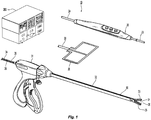
- Fig. 1 is a perspective view of the components of one illustrative embodiment of a bipolar and monopolar electrosurgical system 10 according to the present disclosure.
- the system 10 may include one or more monopolar electrosurgical instruments 20 having one or more active electrodes 23 (e.g., electrosurgical cutting probe, ablation electrode(s), etc.) for treating tissue of a patient.
- Electrosurgical alternating current is supplied to the instrument 20 by a generator 200 via a supply line 24 that is connected to an active terminal 230 ( Fig. 3 ) of the generator 200, allowing the instrument 20 to cut, coagulate, ablate and/or otherwise treat tissue.
- the alternating current is returned to the generator 200 through a return electrode pad 26 via a return line 28 at a return terminal 232 ( Fig.
- the system 10 may include a plurality of return electrode pads 26 that, in use, are disposed on a patient to minimize the chances of tissue damage by maximizing the overall contact area with the patient.
- the generator 200 and the return electrode pads 26 may be configured for monitoring tissue-to-patient contact to ensure that sufficient contact exists therebetween.
- the system 10 may also include one or more bipolar electrosurgical instruments, for example, a bipolar electrosurgical forceps 30 having one or more electrodes for treating tissue of a patient.
- the electrosurgical forceps 30 includes a housing 31 and opposing jaw members 33 and 35 disposed at a distal end of a shaft 32.
- the jaw members 33 and 35 have one or more active electrodes 34 and a return electrode 36 disposed therein, respectively.
- the active electrode 34 and the return electrode 36 are connected to the generator 200 through cable 38 that includes the supply and return lines 24, 28 coupled to the active and return terminals 230, 232, respectively ( Fig. 3 ).
- the electrosurgical forceps 30 is coupled to the generator 200 at a connector having connections to the active and return terminals 230 and 232 (e.g., pins) via a plug disposed at the end of the cable 38, wherein the plug includes contacts from the supply and return lines 24, 28 as described in more detail below.
- the generator 200 may be any suitable type (e.g., electrosurgical, microwave, etc.) and may include a plurality of connectors 250, 252, 254, 256, 258, 260, 262 to accommodate various types of electrosurgical instruments (e.g., electrosurgical forceps 30, etc.).
- electrosurgical instruments e.g., electrosurgical forceps 30, etc.
- the generator 200 includes a user interface 241 having one or more display screens or information panels 242, 244, 246 for providing the user with variety of output information (e.g., intensity settings, treatment complete indicators, etc.). Each of the screens 242, 244, 246 is associated with corresponding connectors 250-262.
- the generator 200 includes suitable input controls (e.g., buttons, activators, switches, touch screen, etc.) for controlling the generator 200.
- the display screens 242, 244, 246 are also configured as touch screens that display a corresponding menu for the electrosurgical instruments (e.g., electrosurgical forceps 30, etc.). The user then adjusts inputs by simply touching corresponding menu options.
- Connector 250 is configured to couple to a monopolar electrosurgical instrument (e.g., electrosurgical instrument 20) and connector 252 is configured to couple to a foot switch (not shown). The foot switch provides for additional inputs (e.g., replicating inputs of the generator 200).
- Connector 254 is configured to couple to electrode pad 26.
- Screen 244 controls monopolar and bipolar output and the devices connected to the connectors 256 and 258.
- Connector 256 is configured to couple to other monopolar instruments.
- Connector 258 is configured to couple to a bipolar instrument (not shown).
- Screen 246 controls bipolar sealing procedures performed by the forceps 30 that may be plugged into the connectors 260 and 262.
- the generator 200 outputs energy through the connectors 260 and 262 suitable for sealing tissue grasped by the forceps 30.
- screen 246 outputs a user interface that allows the user to input a user-defined intensity setting.
- the user-defined setting may be any setting that allows the user to adjust one or more energy delivery parameters, such as power, current, voltage, energy, etc. or sealing parameters, such as energy rate limiters, sealing duration, etc.
- the user-defined setting is transmitted to a controller 224 of generator 200 ( Fig. 3 ) where the setting may be saved in memory 226.
- the intensity setting may be a number scale, such as for example, from one to ten or one to five. In embodiments, the intensity setting may be associated with an output curve of the generator 200.
- the intensity settings may be specific for each forceps 30 being utilized, such that various instruments provide the user with a specific intensity scale corresponding to the forceps 30.
- Fig. 3 shows a schematic block diagram of the generator 200 configured to output electrosurgical energy.
- the generator 200 includes a controller 224, a power supply 227, and a radio-frequency (RF) amplifier 228.
- the power supply 227 may be a high voltage, DC power supply connected to an AC source (e.g., line voltage) and provides high voltage, DC power to the RF amplifier 228 via leads 227a and 227b, which then converts high voltage, DC power into treatment energy (e.g., electrosurgical or microwave) and delivers the energy to the active terminal 230.
- treatment energy e.g., electrosurgical or microwave
- the current is returned thereto via the return terminal 232 as energy is dissipated into the tissue.
- the active and return terminals 230 and 232 are coupled to the RF amplifier 228 through an isolation transformer 229.
- the RF amplifier 228 is configured to operate in a plurality of modes, during which the generator 200 outputs corresponding waveforms having specific duty cycles, peak voltages, crest factors, etc. It is envisioned that in other embodiments, the generator 200 may be based on other types of suitable power supply topologies.
- the controller 224 includes a processor 225 operably connected to a memory 226, which may include transitory type memory (e.g., RAM) and/or non-transitory type memory (e.g., flash media, disk media, etc.).
- the processor 225 includes an output port that is operably connected to the power supply 227 and/or RF amplifier 228 allowing the processor 225 to control the output of the generator 200 according to either open and/or closed control loop schemes.
- a closed loop control scheme is a feedback control loop, in which a plurality of sensors measure a variety of tissue and energy properties (e.g., tissue impedance, tissue temperature, output power, current and/or voltage, etc.), and provide feedback to the controller 224.
- the controller 224 then signals the power supply 227 and/or RF amplifier 228, which adjusts the DC and/or power supply, respectively.
- the processor 225 may be substituted for by using any logic processor (e.g., control circuit) adapted to perform the calculations and/or set of instructions described herein including, but not limited to, field programmable gate array, digital signal processor, and combinations thereof.
- the generator 200 includes a plurality of sensors 280, e.g., an RF current sensor 280a, and an RF voltage sensor 280b.
- Various components of the generator 200 namely, the RF amplifier 228, the RF current and voltage sensors 280a and 280b, may be disposed on a printed circuit board (PCB).
- the RF current sensor 280a is coupled to the plurality of active leads 228a and/or plurality of return leads 228b and provides measurements of the RF current supplied by the RF amplifier 228.
- the RF voltage sensor 280b is coupled to the active and return terminals 230 and 232 and provides measurements of the RF voltage supplied by the RF amplifier 228.
- the RF current and voltage sensors 280a and 280b may be coupled to active and return leads 228a and 228b, which interconnect the active and return terminals 230 and 232 to the RF amplifier 228, respectively.
- the RF current and voltage sensors 280a and 280b provide the sensed RF voltage and current signals, respectively, to the controller 224, which then may adjust output of the power supply 227 and/or the RF amplifier 228 in response to the sensed RF voltage and current signals.
- the controller 224 also receives input signals from the input controls of the generator 200, the instrument 20 and/or forceps 30. The controller 224 utilizes the input signals to adjust the power output by the generator 200 and/or performs other control functions thereon.
- Transformers are conventionally used as current and voltage sensors as they provide a required patient isolation.
- the gain that transformers provide fluctuates due to temperature, signal amplitude, etc. This makes accurate readings difficult with respect to the phase and gain-bandwidth of the sensor signals.
- the signals need to be post-processed to arrive at accurate representations.
- the present disclosure provides for novel current sensor 280a which overcome the problems of conventional sensors.
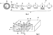
- Fig. 4 shows an RF current sensor 300, which includes a conditioning circuit 301 and a current sensor coil 302.
- the term "current sensor coil” refers to an electrical device for measuring alternating current (e.g., RF current) and includes an outer conductor coil (e.g., toroid) that acts as an active conductor wrapped around an inner conductor, a so-called “Bucking coil” that acts as a return conductor and a lead 228a carrying the current passing through an opening 303 ( Fig. 6 ) in the coil 302.
- the coil 302 may have any suitable shape such as helical, toroidal, etc. In embodiments, the coil may have a polygonal cross-section.
- the current sensor coil 302 may include a low permeability core (e.g., air core) and provides a voltage output having a time-derivative of the current being measured to a conditioning circuit that integrates the output to provide a voltage signal indicative of the current.
- the current sensor coil 302 may be implemented on a printed circuit board and may include an opening so that the current sensor coil 302 may be wrapped about the conductor carrying the current to be measured.
- the current sensor coil 302 may also be implemented using wire and may be wound around a toroidal magnetic core.
- the current sensor coil 302 is coupled to conditioning circuit 301 having a resistor network 304, which includes resistors 304a and 304b.
- the conditioning circuit 301 may be implemented as any integrator (e.g., logic processor) or differential amplifier.
- the resistor network 304 removes resonance of the coil 302 at its resonant frequency.
- the current sensor coil 302 is disposed about one or more active leads 228a and the coil 302 is configured to measure the current passing therethrough as a sensor signal.
- the sensor signal from the coil 302 is then supplied to an optional gain amplifier 306 which increases the amplitude of the sensor signal and buffers the coil 302.
- the amplifier 308 is a differential-to-single-ended converter whose function is to convert the differential signal from the coil 302 to a single-ended signal.
- the amplifier 308 may have a monolithic configuration that provides improved common mode rejection.
- the bandpass filter 310 removes higher and lower frequency components of the sensor signal which is then transmitted to an integrator 312. Since the voltage that is induced in the current sensor coil 302 is proportional to the rate of change of current that is flowing through the active lead 228a, the integrator 312 is utilized to provide an output sensor signal that is proportional to the current.
- the integrator 312 may be coupled to a switchable attenuation circuit 314, which may include one or more actively switched components.
- the attenuation circuit 314 may then be coupled to additional components such as an offset circuit 316, analog-digital converters, and the like prior to supplying the signal to the controller 224.
- Figs. 5-9 show the current sensor coil 302 according to the present disclosure.
- the coil 302 has a substantially circular shape having an opening 303 ( Fig. 6 ) defined therethrough.
- the active lead 228a is disposed through the opening 303 of the coil 302, allowing the coil 302 to measure the current flow through the active lead 228a. If the return lead 228b is also being measured, additional traces may be used to provide for passage through the opening 303 of the current sensor coil 302 as described in detail below with respect to Figs. 17-33 .
- the coil 302 has a substantially toroidal shape and is formed on a printed circuit board (PCB) 400 and includes an inner circumferential region 302a and an outer circumferential region 302b.
- the coil 302 includes forming an inner portion ("Bucking coil") 405 of the coil 302 and an outer coil 407.
- the coil 302 may have any other suitable shape (e.g., having a polygonal cross-section) with the outer coil 407 wrapped about the inner coil 405 and defining an opening through the coil 302.
- the coil 302 may be a coil-wrapped phenolic toroid having a low permeability ( ⁇ 0 ).
- the magnetic field is reflective of the current Ip passing only through the active lead 228a.
- the outer coil 407 detects the magnetic field in either embodiment and produces a first voltage corresponding to the first magnetic field.
- the outer coil 407 also may detect a second unwanted magnetic field and produces a second voltage corresponding to the second magnetic field.
- the second magnetic field is orthogonal to the first magnetic field and is not related to the sensed current.
- the inner coil 405 senses the second magnetic field and produces a third voltage proportional to the second magnetic field.
- the second voltage and third voltage produced have approximately the same magnitude such that they cancel each other.
- the plurality of active leads 228a and/or plurality of return leads 228b are disposed together, the current flowing through the active leads 228a and return leads 228b produce a net first magnetic field proportional to the sensed current Is.
- the PCB 400 may be a multilayer PCB formed from any suitable dielectric material, including, but not limited to composite materials composed of woven fiberglass cloth with an epoxy resin binder such as FR-4 grade as designated by National Electrical Manufacturers Association. As shown in Fig. 8 , the PCB 400 includes a first or top layer 404a and a bottom layer 404e. For simplicity Fig. 5 , Fig. 6 , Fig. 8, and Fig. 9 will show only the active lead 230. It will be understood that in every case a plurality of active leads and/or a plurality of return leads may be used.
- the active lead 228a is coupled to conductive traces 408a and 408f, respectively, which are disposed over the top and bottom layers 404a and 404e as shown in Figs. 8 and 9 .
- the active lead 228a may be coupled to a patient side connector 420 disposed on the PCB 400 as shown in Fig. 9 .
- the traces 408a and 408f are interconnected through the opening 303 ( Fig. 6 ) using one or more vias 409a, which pass through the entire PCB 400 (e.g., layers 404a-404e).
- the outer coil 407 includes a top trace 408b disposed between the top layer 404a and an intermediate layer 404b of the PCB 400.
- the outer coil 407 also includes a bottom trace 408e disposed between the bottom layer 404e and an intermediate layer 404d of the PCB 400.
- the traces 408b and 408e are interconnected by a plurality of inner vias 409b and outer vias 409c.
- the layers 404a and 404e insulate the coil 302 (e.g., outer coil 407) conductive traces 408a and 408f and provide an isolation barrier between the patient and the generator 200.
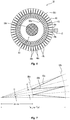
- the inner vias 409b are arranged to form the inner circumferential region 302a of the coil 302 and the outer vias 409c form the outer circumferential region 302b of the coil 302.
- the inner and outer vias 409b and 409c pass through the layers 404b, 404c, and 404d.
- the inner vias 409b and outer vias 409c may be disposed in a concentric configuration. In a non-staggered configuration, corresponding inner and outer vias 409b and 409c lie along same rays. In a staggered configuration, the inner and outer vias 409b and 409c lie along alternating rays "r" as shown in Figs. 5-7 .
- the rays "r" are disposed at and an angle " ⁇ " relative to each other and the inner vias 409b are separated by a distance "d.”
- Each of the inner vias 409b is connected to two neighboring outer vias 409c through traces 408b and 408e and vice versa.
- the interconnection of the vias 409b and 409c with the traces 408b and 408e forms a plurality of loops, which in turn, form the outer coil 407 as shown in Fig. 5 .
- the outer coil 407 may include any suitable number of turns, in embodiments from about 50 turns to about 100 turns. The maximum number of turns depends on the radius of the inner circumferential region 302a, via aspect ratio, thickness of the outer coil traces 407 and/or PCB 400, and spacing between the turns based on the limits of manufacturability of the PCB material (e.g., trace to trace, trace to via, via annular pad dimension, anything that may limit the placement of the conductors on the PCB).
- the inner coil 405 is disposed within the outer coil 407 and also has a substantially circular shape.
- the inner coil 405 may include an upper trace 408c and a bottom trace 408d.
- the traces 408c and 408d are disposed over a dielectric layer 404c, such that the traces 408c and 408d are insulated from each other.
- the traces 408c and 408d may be electrically coupled to each other.
- the inner coil 405 may be formed from a single trace.
- the coil 302 is coupled to the conditioning circuit 301 at a side connector 422, which may also be disposed on the PCB 400.
- the coil 302 includes a first terminal 410a coupled to the inner coil 405 and a second terminal 410b coupled to the outer coil 407.
- the outer coil 407 is disposed over the inner coil 405 and is coupled thereto.
- two terminals 410a and 410b are disposed at one end of the coil 302.
- the interconnection between the inner coil 405 and the outer coil 407 as well as the connection to the terminals 410a and 410b may be made through the vias 409b and 409c.
- the controller 224 is provided to sensor signals from the sensor 300, which are then utilized to determine the current. Various formulas may be utilized by the controller 224 to determine the current.
- A is the area of the turn (e.g., loop) formed by the vias 409b and 409c with the traces 408b and 408e
- N is the number of turns
- R is the major radius of the coil 302
- ⁇ 0 is the magnetic constant
- dl/dt is the rate of change of the current being measured by the coil 302.
- Inductance and capacitance of the coil may be calculated using the formulae (II) - (IV), respectively.
- Capacitance of the coil 302 is used to determine self-resonance and may be calculated using parallel-wire model formulae, namely, capacitances of inner and outer vias 409b and 409c and traces 408b and 408e.
- t is thickness (e.g., distance between conductive traces 408b and 408e), r is radius, w is the radial distance between inner and outer circumferential regions 302a and 302b, Rcoil inner is the radial distance to the inner circumferential region 302a, 1 is length, ⁇ 0 is vacuum permittivity constant, and ⁇ r is the relative dielectric constant of the PCB.
- conditioning circuit 301 of the sensor 300 is shown. Since the coil 302 provides a differentiating response, the output must be integrated to provide the actual response through the conditioning circuit 301 of the sensor 300. The output of the coil 302 is integrated to produce a signal that is proportional to the current in the active lead 228a.
- the conditioning circuit 301 provides integration with the integrator 312. This allows for easy adjustability of the sensor gain, utilization in the control loop and processing by an analog-digital converter. Gain may be set by adjusting the frequency setpoint of the integrator 312.
- the setpoint may be achieved by selection of hardware component values (e.g., discrete resistor or capacitor substitution), selection of software values (e.g., digital or analog potentiometers or adjustable capacitors), including programmable gain amplifiers as described in detail below, or combinations thereof.
- hardware component values e.g., discrete resistor or capacitor substitution
- software values e.g., digital or analog potentiometers or adjustable capacitors
- programmable gain amplifiers as described in detail below, or combinations thereof.
- the gain amplifier 306 of the conditioning circuit 301 is shown in Fig. 10 and includes a pair of operational amplifiers 306a and 306b configured to provide differential gain without adding to the common-mode gain.
- the sensor signal from the coil 302 is provided to the positive terminals of the amplifiers 306a and 306b.
- the outputs of the amplifiers 306a are interconnected by a gain setting voltage divider network 306c including three resistors 306d, 306e, 306f. Terminal resistors 306d and 306f are coupled in parallel with capacitors 306g and 306h, respectively.
- the signal from the parallel circuits is coupled to the negative terminals of the amplifiers 306a and 306b, which provide closed-loop feedback thereto.
- Capacitors 306g and 306h provide amplifier stabilization and may also provide for the integration of the signal.
- each of the operational amplifiers 306a and 306b is provided to the differential to single-ended amplifier 308, which is shown in Fig. 11 .
- the output of the amplifiers 306a and 306b is supplied to the positive and negative inputs of the amplifier 308.
- the amplifier 308 combines the output of the amplifiers 306a and 306b to provide a single output to the bandpass filter 310.
- the amplifier 308 includes a closed feedback circuit having a reference signal connected to ground including a resistor 308a, which is connected in series with a capacitor 308b that is coupled in parallel with a resistor 308c.
- the bandpass filter 310 includes a high-pass filter 309 and a low-pass filter 311 as shown in Figs. 12 and 13 , respectively. In embodiments, the output from the amplifier 308 may be passed through the high-pass filter 309 before being passed through the low-pass filter 311, or vice versa.
- the high-pass filter 309 is configured to pass high frequencies and attenuate lower frequencies.
- the high-pass filter 309 includes an operational amplifier 309a.
- the output from the amplifier 308 is provided to the input of the amplifier 309a through a first capacitor 309b coupled in series with a second capacitor 309c and a first resistor 309d and a second resistor 309e.
- the negative input of the amplifier 309a is provided by a feedback loop from a third resistor 309f coupled in series with a grounded fourth resistor 309g.
- the low-pass filter 311 is configured to pass low frequencies and attenuates higher frequencies.
- the low-pass filter 311 includes an operational amplifier 311a.
- the input from the high-pass filter 309 is provided to the input of the amplifier 311a through a first resistor 311b coupled in series with a second resistor 311c and a first capacitor 311d and a second capacitor 311e.
- the negative input of the amplifier 311a is provided by a feedback loop from a third resistor 311f coupled in series with a grounded fourth resistor 311g.
- the integrator 312 is utilized to provide an output signal that is proportional to the sensed current.
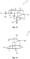
- a leaky integrator may be used.
- the term "leaky integrator” refers to an integrator having a low-pass filter as described in further detail below with respect to Fig. 14 .
- the integrator 312 includes an amplifier 312a with a positive input thereof coupled to a ground.
- the input from the bandpass filter 310 is fed through a low-pass filter 312b, which includes a first resistor 312c coupled in series with a second resistor 312d that is coupled in parallel with a capacitor 312e.
- the second resistor 312d and the capacitor 312e are also coupled to the output of the amplifier 312a thereby providing a closed loop feedback thereto.
- the input signal is then fed to the negative input of the amplifier 312a.
- the integrator 312 provides a negative slope of voltage gain verses frequency. This compensates, or flattens the opposite slope of the signal coming from the coil 302. Further, the integrator 312 has extremely high DC gain.
- the frequency band of interest for the generator 200 is well above DC. The integrator gain would create problems if a DC offset were present at its input.
- the high-pass portion of the band-pass filter 310 reduces the low frequency components and reduces any DC offset, which mitigates issues caused by the integrator's amplification of these components.
- Fig. 15 shows a graph 500 illustrating individual gain response of the coil 302, the integrator 312, and the combined response of the coil 302 and the integrator 312.
- the graph 500 shows the overall response of the coil 302 as a plot 502, the response of the integrator 312 as a plot 504, and the combined response of the coil 302 and the integrator 312 of the sensor 300 as a plot 506, which is a combination of the plots 502 and 504.
- Frequency, f1 is determined by the response of the integrator 312 and frequency, f2, is determined by the resonant frequency of the coil 302.
- the active lead 228a carries both common-mode (CM) and differential-mode (DM) current.
- CM common-mode
- DM differential-mode
- CM current can provide useful data.
- having a system and method of separating the DM current from the CM current in a conductor would then allow for more accurate sensors.
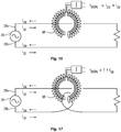
- the CM current and DM current are indistinguishable from one another.
- the CM currents on the active lead 228a and return lead 228b pass through the center of the current sensor 600, but in opposite directions.
- the flux produced by CM currents cancel each other out, and the current sensor 600 produces zero signal in proportion to the CM current.
- the DM currents pass through the current sensor 600 in the same direction due to the routing of the active lead 228a and return lead 228b, namely, looping of the return lead 228b.
- the flux produced by DM currents are additive, and the current sensor 600 produces a signal that is based on the sum of (e.g., twice of) the DM current. If an iron or ferrite core is being used, then V signal is proportional to the DM current, thus in Fig.
- V signal is proportional to the sum of CM and DM currents and in Fig. 17 V signal is proportional to the sum of only the DM currents. If an air core is being used, then V signal is proportional to time rate of change of V signal , thus in Fig. 16 , V signal is proportional to a derivative of the sum of CM and DM currents and in Fig. 17 V signal is proportional to the sum of time derivative of only the DM currents.
- the above-described embodiment is related to a Rogowski coil as a current sensor, the disclosed orientation of the active and return leads may be applied to any type of a current-sense transformer.
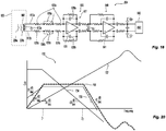
- Fig. 18 shows a current sensor assembly 604 including the differential-mode RF current sensor 600 and a fully differential condition circuit 650 according to the present disclosure.
- the current sensor 600 includes a current sensor coil 602 and is shown schematically in Fig. 19 .
- the current sensor 600 is configured to measure individual first and second currents of active and return leads 228a and 228b or a net current.
- Current transformers are configured to measure either common-mode current or differential-mode current flow. In a typical application using power electronics, such as an inverter for generating alternating current, complex currents flow which have both differential and common-mode components which make up the totality of the flowing current.
- the current flowing through each of the leads 228a and 228b generates a corresponding magnetic field within the current sensor 600.
- the net magnetic field then affects the current sensor 600, which detects the differential-mode current.
- the embodiment of the current sensor coil 602 of Fig. 19 is configured as a differential-mode current sensor since it allows for use with multiple active and return leads 228a, 228b and 228c, 228d ( Fig. 33 ).
- the current sensor 600 and the conditioning circuit 650 provide a completely differential signal, which provides better noise immunity.
- First and second terminals 612a and 612b of the current sensor coil 602 are coupled to the conditioning circuit 650.
- Current sensor coil 602 also includes a third terminal 612c as described in further detail below with respect to Fig. 26A .
- Each of the first and second terminals 612a, 612b is coupled to a differential integrator 637, which includes a plurality of resistors 635a, 635b.
- the differential integrator 637 compensates for the derivative nature of the sensor signal from the current sensor coil 602 as described above with respect to the current sensor coil 302.
- One or more of the resistors 635a, 635b may be coupled to differential gain switches (e.g., MOSFETs, analog swtiches, relays etc.) 636a, 636b, respectively.
- the switches 636a, 636b are configured to change the value of the resistors 635a, 635b, respectively, to adjust the gain of the conditioning circuit 650.
- the resistors 635a, 635b are coupled to input terminals of an amplifier 638.
- the differential integrator 637 also includes capacitors 638a, 638b coupled to the amplifier 638.
- the differential integrator 637 is, in turn, coupled to an active bandpass filter 640, which also includes an amplifier 641 and associated circuit components.
- the bandpass filter 640 is then coupled to an analog-to-digital converter 642, which then transmits the converted digital signal to the controller 224.
- Fig. 20 is a graph 700 of a gain response of the current sensor assembly 604 of Fig. 18 according to the present disclosure.
- the graph 700 shows individual and combined gain responses of the current sensor coil 602, differential integrator 637, and the bandpass filter 640.
- the graph 700 shows the overall response of the current sensor coil 602 as a plot 702, the response of the differential integrator 637 as a plot 704, and the response of the bandpass filter 640 as a plot 706.
- the graph 700 also shows the combined response of the current sensor coil 602, differential integrator 637, and the bandpass filter 640 as a plot 708, which is a combination of the plots 702, 704, and 706.
- Frequency, f1 is determined by the response of the differential integrator 637 and the bandpass filter 640
- frequency, f2 is determined by the bandpass filter 640.
- the RF energy passing through the leads 228a and 228b may have relatively high voltage but low current.
- Undesired voltage signal from the leads 228a and 228b, which acts as primary conductors can couple to the current sensor coil 602, which acts as a secondary winding, producing a significant error signal.
- the present disclosure provides for systems and methods for reducing the error signal due to voltage coupling between the active leads 228a and 228b and the current sensor coil 602.
- the present disclosure provides for specific arrangement of the active and/or return leads 228a, 228b relative to the current sensor coil 602 such that the undesired voltage signal is coupled as a common-mode signal and is then cancelled or reduced by the common rejection capabilities of the conditioning circuit 650.
- the present disclosure also provides for shielding the current sensor coil 602 to minimize coupling of the voltage signal.
- any combinations of arrangement of the active and/or return leads 228a, 228b and/or shielding may be utilized to minimize coupling of the voltage signal.
- FIGs. 21 and 22 illustrate the generator 200 including the RF amplifier 228 supplying RF current, Ip, through the active lead 228a with the current sensor coil 602 sensing the primary current, Ip, passing therethrough.
- the primary current, Ip induces a secondary current, Is, in the current sensor coil 602, which develops a voltage, Vo.
- the resulting Vo should also be near zero.
- the high voltage capacitively couples from the active lead 228a to the current sensor coil 602, as represented schematically by a parasitic capacitance Cp1, which produces an erroneous output voltage.
- Fig. 23 shows an embodiment of the present disclosure for reducing or eliminating erroneous output voltage signal output by the conditioning circuit 650.
- the present disclosure provides for a system of positioning the active leads 228a and/or return leads 228b in such a way as to balance the capacitive coupling therefrom to the current sensor coil 602.
- the conditioning circuit 650 then reduces the erroneous output voltage due to its common-mode rejection capability.
- the active lead 228a is passed through the current sensor coil 602 to generate a second parasitic coupling capacitance, Cp2, which is also coupled to the current sensor coil 602.
- Cp2 the capacitances Cp1 and Cp2 are coupled symmetrically about the sensor current sensor coil 602.
- the capacitance Cp2 couples a voltage from the active lead 228a to the current sensor coil 602 similarly to the capacitance Cp1, thereby balancing the circuit such that the resulting voltage is a common-mode voltage, which is then rejected by the conditioning circuit 650.
- Fig. 24 shows another embodiment of the present disclosure for reducing or eliminating erroneous output voltage by the conditioning circuit 650.
- the current sensor 600 includes one or more shielding members 606 disposed between the active leads 228a and the current sensor coil 602 to prevent or reduce the voltage coupling from active lead 228a to current sensor coil 602.
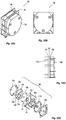
- Figs. 25A-E show an embodiment of the current sensor 600 including a circular current sensor coil 602 disposed on a printed circuit board (PCB) 601, which may be formed using the techniques described above with respect to the current sensor coil 302 of Figs. 5-9 .
- the current sensor 600 includes one or more active leads 228a, 228c and return leads 228b, 228d passing through an opening 603 of the current sensor coil 602.
- the leads 228a, 228b, 228c, 228d may be any suitable conductive leads (e.g., wires) having an insulating sheath.
- the leads 228a, 228b, 228c, 228d may be printed as conductive traces on the PCB 601 and passed through the current sensor coil 602 as vias, such as traces 408a and 408f and via 409a as described above with respect to Figs. 5 and 9 .
- the current sensor 600 also includes a pair of shielding members 606a and 606b disposed over upper and lower surfaces of the current sensor coil 602.
- the shielding member 606a is shown and described, which is substantially similar to the shielding member 606b.
- the shielding member 606a is formed from a conductive material and is coupled to a ground “g" as shown in Fig. 24 .
- the shielding member 606a includes an opening 608 therethrough for passage of leads 228a, 228b, 228c, 228d.
- the shielding member 606a is configured and dimensioned to substantially cover the current sensor coil 602. Since the current sensor coil 602 is disposed on the PCB 601, the shielding members 606a and 606b may be substantially flat.
- the shielding member 606a may be a discrete conductive layer attached to the PCB 601 on which the current sensor coil 602 is disposed using any suitable fasteners, adhesives, and combinations thereof.
- the shielding members 606a, 606b may be formed as layers on the PCB 601 as shown in Fig. 25E .
- the PCB 601 may include additional dielectric layers (e.g., outer dielectric layers) to accommodate the shielding members 606a, 606b as integrated layers.
- the shielding members 606a, 606b may be printed as a conductive layer on the PCB 601 as described above with respect to the printing of the current sensor coil 302. This configuration may be used in embodiments in which the leads 228a, 228b, 228c, 228d are formed as vias and traces.
- an additional dielectric layer may be disposed on top of the conductive trace 408b ( Fig. 8 ), on top of which the shielding member 606a is then formed, as well as below conductive trace 408e ( Fig. 8 ), below which the shielding member 606b is then formed.
- the current sensor 600 also includes a pair of opposing spacers 610a and 610b.
- the spacers 610a and 610b are formed from a dielectric material and when assembled define an opening therethrough which aligns with the opening 603 of the current sensor coil 602.
- the leads 228a, 228b, 228c, 228d are wrapped around and through the spacers 610a and 610b as shown in Fig. 25D to maintain the leads 228a, 228b, 228c, 228d in a predetermined spatial relationship relative to themselves and the current sensor coil 602 to cancel and/or reduce the effects of parasitic capacitance as described above.
- the current sensor 600 also includes a pair of opposing housing portions 630a, 630b enclosing the interior components of the current sensor 600.
- the housing portions 630a, 630b also secure leads 228a, 228b, 228c, 228d relative to each other and the current sensor coil 602.
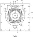
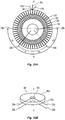
- the coil 602 includes forming an inner coil 605 and an outer coil 607.
- the current sensor coil 602 at a first end 609 includes two terminals 612a and 612b coupled to the outer coil 607 and the third terminal 612c coupled the inner coil 605.
- the third terminal 612C also couples the inner coil 605 to the ground at the first end 609.
- the inner coil 605 center taps the outer coil 607 at a second end 611 as described in further detail below with respect to Figs. 26B and 26C .
- the outer coil 607 includes a semi-circular first portion 607a and a semi-circular second portion 607b and the inner coil 605 includes a semi-circular first portion 605a and a semi-circular second portion 605b.
- the first and second portions 605a, 605b and 607a, 607b are disposed symmetrically (e.g., on left and right sides) about an axis "X-X" defined between diametrically opposed (e.g., 180° apart) first and second ends 609 and 611 of the current sensor coil 602, respectively.
- the first portion 607a of the outer coil 607 is coupled between the first terminal 612a on top (e.g., at first end 609) and a first connection 611a of the first portion 605a of the inner coil 605 on the bottom (e.g., at second end 611).
- the second portion coil 607b of the outer coil 607 is coupled between the second terminal 612b on top (e.g., at first end 609) and a second connection 611b of the second portion 605b of the inner coil 605 on bottom (e.g., at second end 611).
- Each of the first and second portions 605a, 605b of the inner coil 605 is coupled between the third terminal 612c at the first end 609 of the current sensor coil 602 and their respective connections 611a, 611b at second end 611 of the current sensor coil 602.
- a top portion of the active lead 228a is passed across a top surface 602a of the current sensor coil 602 and is disposed in a - ⁇ orientation, e.g., at an angle ⁇ relative to the axis "X-X.”
- a bottom portion of active lead 228 extends through the opening 603 and across a bottom surface 602b of the current sensor coil 602 such that the bottom portion of active lead 228a is disposed in a + ⁇ orientation relative to the axis "X-X.”
- movement in the - ⁇ direction along sensor coil 602 in Fig. 26D corresponds to movement in a downwardly direction along sensor coil 602 in Fig. 26F .
- movement in the + ⁇ direction along sensor coil 602 in Fig. 26D corresponds to movement in an upwardly direction along sensor coil 602 in Fig. 26F .
- the active lead 228a is disposed symmetrically about the axis "X-X" across the top and bottom surfaces 602a, 602b of the current sensor coil 602 such that the erroneous voltage signals, Ve, generated by the active lead 228a are canceled out.
- the portion of the active lead 228a disposed on the top surface 602a and the portion of the active lead 228a disposed on the bottom surface 602b are symmetrical about the axis "X-X.”
- the top portion of active lead 228a creates capacitive coupling or parasitic capacitance C t within the sensor soil 602 at location L1 ( Fig. 26F ). Similarly, the bottom portion of active lead 228a creates capacitive coupling or parasitic capacitance C b within sensor coil 602 at location L2 ( Fig. 26F ).
- Two operating points identified as "P1" and "P2" in Fig. 26E correspond to locations L1 and L2, respectively, in Fig. 26F .
- An error signal Ve is generated at location L1 and an error signal Ve is created at location L2.
- the capacitive coupling is balanced, causing the erroneous signal to be a common-mode voltage.
- the differential circuitry causes the erroneous error signal to be removed.
- the embodiments of sensor circuit 602 provided above are balanced, have shielding, or are both balanced and have shielding such that the circuits produce little to no output signal Vx when there is no input current.
- Fig. 26E shows a plot 800 illustrating a logarithmic ratio of output voltage Vx of the amplifier to the voltage on active lead 228a vs. angular location.
- the logarithmic ratio is calculated using the equation of 20Log(IV x I/IV in I), in which Vx is the output of the differential amplifier and V in is the voltage on active lead 228a.
- Operating points "P1" and “P2" correspond to the locations L1 and L2 of the parasitic capacitances C t , C b shown in Fig. 26F .
- the slope of the graph illustrates sensitivity, i, of the output voltage Vx of the differential amplifier as a function of positional angle between the axis "X-X" and the active lead 228a.
- the sensitivity to erroneous voltage signals Ve of the current sensor coil 602 decreases. This relationship may be used to locate the active lead 228a relative to the axis "X-X" to obtain the most accurate reading of the current passing therethrough while minimizing the interference caused by the erroneous voltage signals Ve.
- sensor coil 602 includes a length of wire, namely the inner coil 605, passing through the middle of the sensor coil 602 such that the wire extends from a first end 609 to a second end 611 of sensor coil 602.
- the top surface of sensor coil 602 in Fig. 27A corresponds to the left side of sensor coil 602 in Fig. 27B .
- the bottom surface of sensor coil 602 in Fig. 27A corresponds to the right side of sensor coil 602 in Fig. 27B .
- sensor coil 602 is shown, differing from sensor coil 602 shown in Fig. 27A by the addition of wire 228a running through the central opening in sensor coil 602. Assuming there is no current traveling through the wire 228a, the output of the sensor coil 602 should be ideally zero.
- the wire 228a is in close proximity to the sensor coil 602 and will capacitively couple via Ct an undesired error voltage, Ve, from the wire 228a to the sensor coil 602.
- the position of wire 228a relative to the sensor coil 602 determines the location at which the error voltage is coupled, and thus affects how the circuit processes the signal. This, in turn, affects the output signal Vo.
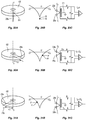
- Figs. 29A-C, Figs. 30A-C, and Figs. 31A-C show additional single-wire configurations of the sensor coil 602.
- the wire 228a is routed on the top and the bottom of sensor coil 602.
- each of the top and bottom portions of wire 228a couples to the sensor coil 602 forming a parasitic capacitance C t , C b , as shown in Fig. 29C .
- both C t and C b are at 0 degrees relative to the axis "X-X,” they are capacitvely coupled to the center tap of the sensor coil 602, which is grounded and therefore signal Ve is zero, hence, Vx is also zero.
- this configuration provides for a low error signal, any movement in ⁇ yields a large change in error voltage.
- Fig. 30A shows both top and bottom portions of active lead 228a disposed in + ⁇ direction.
- the top and bottom portions of active lead 228a are capacitively coupled at the same location due to the overlap of the active lead 228a on the sensor coil 602, but off the center tap due to the placement of active lead 228a in Fig. 30A as compared to the configuration shown in Figs. 29A-C .
- An error signal Ve is coupled into the sensor coil 602 by each of the top and bottom portions of the active lead 228a. This corresponds to the operating points "P1" and "P2" shown in Fig. 30B representative of error signal.
- Fig. 31A shows the top and bottom portions of active lead 228a moved in the - ⁇ direction.
- the the top and bottom portions of active lead 228a are capacitively coupled at the same location due to the overlap of the active lead 228a on the sensor coil 602, but off the center tap due to the placement of active lead 228a in Fig. 31A as compared to the configuration shown in Figs. 29A-C .
- An error signal Ve is coupled into the sensor coil 602 by each of the top and bottom portions of the active lead 228a. This corresponds to the operating points "P1" and "P2" shown in Fig. 31B representative of error signal.
- a two-wire orientation of the active lead 228a and return lead 228b about the current sensor coil 602 is shown schematically.
- the active and return leads 228a, 228b are passed across the top surface 602a of the current sensor coil 602, through the opening 603, and across the bottom surface 602b of the current sensor coil 602.
- the top and bottom portions of the active lead 228a are symmetrical about the axis "X-X" at a first angle, - ⁇ and + ⁇ , respectively
- the top and bottom portions of the return lead 228b are symmetrical about the axis "X-X" at a second angle, + ⁇ and - ⁇ , respectively.
- the active and return leads 228a, 228b may be disposed at an angle ⁇ , ⁇ , respectively, from about 0° to about 90° relative to the axis "X-X.”
- angles ⁇ , ⁇ may be the same, as shown in Fig. 32B , or different, as shown in Fig. 32A .
- multiple active leads 228a and 228c and multiple return leads 228b and 228d may be used depending on the number of outputs within the generator 200, e.g., bipolar, monopolar, etc.
- the active and return leads 228a, 228c and 228b, 228d are also disposed in a symmetrical relationship (e.g., transverse to the axis "X-X") relative to each other about the axis "X-X,” such that the erroneous voltage signals are cancelled.
- any number of active and return leads 228a, 228c and 228b, 228d may be wrapped about the current sensor coil 602 as illustrated in Fig. 33 .
- This configuration may include two pairs of active and return leads 228a, 228c, and 228b, 228d, which may be disposed in an overlapping relationship, such that active and return leads 228a, 228c and 228b, 228d, respectively are disposed over each other.
- This arrangement may be used with a differential-mode current transformer configuration.
Landscapes
- Physics & Mathematics (AREA)
- General Physics & Mathematics (AREA)
- Engineering & Computer Science (AREA)
- Power Engineering (AREA)
- Surgical Instruments (AREA)
- Measuring Instrument Details And Bridges, And Automatic Balancing Devices (AREA)
Claims (13)
- Sensor (600) zum Erfassen von Strom, wobei der Sensor umfasst:eine Stromsensorspule (602), die eine Öffnung durch sie hindurch definiert, beinhaltend:eine äußere Spule (607); undeine innere Spule (605), die mit der äußeren Spule gekoppelt und innerhalb dieser angeordnet ist; undaktive Leitungen (228a), Rückleitungen (228b) oder mindestens eine aktive Leitung (228a) und mindestens eine Rückleitung (228b), die durch die Öffnung der Stromsensorspule verlaufen, wobei die Stromsensorspule so konfiguriert ist, dass sie entsprechende Signale ausgibt, die den Strom in den durch die Öffnung der Stromsensorspule verlaufenden Leitungen anzeigen; undwobei die Stromsensorspule diametral gegenüberliegende erste und zweite Enden (609, 611) beinhaltet und sowohl die äußere Spule als auch die innere Spule erste und zweite Abschnitte (605a, 605b, 607a, 607b) beinhaltet, wobei die ersten und zweiten Abschnitte an dem zweiten Ende getrennt sind;dadurch gekennzeichnet, dassdie Leitungen, die durch die Öffnung der Stromsensorspule verlaufen, symmetrisch über der Stromsensorspule um eine Achse ("X"-"X") angeordnet sind, die zwischen dem ersten und dem zweiten Ende definiert ist, wobei die Leitungen, die durch die Stromsensorspule verlaufen, in einem Winkel ungleich Null (α) relativ zu der Achse angeordnet sind.
- Sensor nach Anspruch 1, wobei die durch die Stromsensorspule verlaufenden Leitungen quer zur Achse angeordnet sind.
- Sensor nach Anspruch 1 oder 2, ferner umfassend:
eine Konditionierungsschaltung (650), die so konfiguriert ist, dass sie das Differenzsignal mindestens entweder integriert, verstärkt oder filtert, um ein verarbeitetes Signal auszugeben, das den Strom anzeigt. - Sensor nach Anspruch 1, 2 oder 3, ferner umfassend:
mindestens ein Abschirmelement (606), das über der äußeren Spule angeordnet ist. - Sensor nach einem der vorhergehenden Ansprüche, wobei die Stromsensorspule innerhalb einer Leiterplatte (601) angeordnet ist, wobei die Leiterplatte vorzugsweise beinhaltet:
mehrere äußere Leiterbahnen, die jeweils mit entsprechenden Leitungen gekoppelt sind, die durch die Öffnung der Stromsensorspule verlaufen, wobei die mehreren äußeren Leiterbahnen durch mindestens eine Durchkontaktierung durch die Leiterplatte miteinander verbunden sind. - Sensor nach Anspruch 5, wobei die Leiterplatte beinhaltet:eine obere dielektrische Schicht;eine erste dielektrische Zwischenschicht;eine untere dielektrische Schicht; undeine zweite dielektrische Zwischenschicht; undwobei die äußere Spule beinhaltet:mehrere obere Leiterbahnen, die zwischen der oberen dielektrischen Schicht und der ersten dielektrischen Zwischenschicht der Leiterplatte angeordnet sind;mehrere untere Leiterbahnen, die zwischen der unteren dielektrischen Schicht und der zweiten dielektrischen Zwischenschicht der Leiterplatte angeordnet sind, wobei die äußeren Leiterbahnen über äußeren Oberflächen der unteren und oberen dielektrischen Schichten angeordnet sind; undmehrere innere und äußere Durchkontaktierungen, die die mehreren oberen und unteren Leiterbahnen miteinander verbinden.
- Sensor nach Anspruch 6, wobei die innere Spule beinhaltet:
mindestens eine Leiterbahn, die innerhalb der äußeren Spule und zwischen der ersten und zweiten dielektrischen Zwischenschicht der Leiterplatte angeordnet ist. - Sensor nach Anspruch 4 zusätzlich zu Anspruch 6 oder 7, wobei das Abschirmelement über einer äußeren dielektrischen Schicht angeordnet ist, die über der äußeren Oberfläche der oberen dielektrischen Schicht und/oder der unteren dielektrischen Schicht angeordnet ist.
- Sensor nach einem der vorhergehenden Ansprüche in Abhängigkeit von Anspruch 2, wobei die Konditionierungsschaltung einen ersten und einen zweiten Anschluss beinhaltet, die mit dem ersten bzw. zweiten Abschnitt der äußeren Spule gekoppelt sind, und der erste und zweite Abschnitt der inneren Spule mit einem dritten Erdungsanschluss am ersten Ende gekoppelt sind, wobei vorzugsweise die ersten Abschnitte der äußeren Spule und der inneren Spule am zweiten Ende miteinander gekoppelt sind und die zweiten Abschnitte der äußeren Spule und der inneren Spule am zweiten Ende miteinander gekoppelt sind.
- Sensor nach einem der vorhergehenden Ansprüche in Abhängigkeit von Anspruch 3, wobei die Konditionierungsschaltung vollständig differenziell ist.
- Sensor nach Anspruch 1 oder 2, wobei:
die Stromsensorspule diametral gegenüberliegende erste und zweite Enden (609, 611) definiert, wobei die Stromsensorspule beinhaltet:die äußere Spule, die einen ersten halbkreisförmigen Abschnitt und einen zweiten halbkreisförmigen Abschnitt (607a, 607b) beinhaltet; unddie innere Spule, die innerhalb der äußeren Spule angeordnet ist und einen ersten halbkreisförmigen Abschnitt und einen zweiten halbkreisförmigen Abschnitt (605a, 605b) beinhaltet, wobei die ersten halbkreisförmigen Abschnitte und die zweiten halbkreisförmigen Abschnitte der inneren und der äußeren Spule an dem zweiten Ende getrennt sind. - Sensor nach Anspruch 11, ferner umfassend mindestens ein Abschirmelement (606), das über der äußeren Spule angeordnet ist und eine zweite Öffnung durch sie hindurch in Ausrichtung mit der Öffnung der Stromsensorspule definiert.
- Sensor nach Anspruch 11 oder 12, ferner umfassend:
eine Konditionierungsschaltung (650), die mit der inneren und der äußeren Spule am ersten Ende gekoppelt und so konfiguriert ist, dass sie das Differenzsignal mindestens entweder integriert, verstärkt oder filtert, um ein Signal auszugeben, das den Strom anzeigt.
Applications Claiming Priority (1)
| Application Number | Priority Date | Filing Date | Title |
|---|---|---|---|
| US14/557,557 US10281496B2 (en) | 2014-12-02 | 2014-12-02 | Electrosurgical generators and sensors |
Publications (2)
| Publication Number | Publication Date |
|---|---|
| EP3028656A1 EP3028656A1 (de) | 2016-06-08 |
| EP3028656B1 true EP3028656B1 (de) | 2021-03-31 |
Family
ID=54360170
Family Applications (1)
| Application Number | Title | Priority Date | Filing Date |
|---|---|---|---|
| EP15191279.7A Active EP3028656B1 (de) | 2014-12-02 | 2015-10-23 | Elektrochirurgische sensoren |
Country Status (2)
| Country | Link |
|---|---|
| US (1) | US10281496B2 (de) |
| EP (1) | EP3028656B1 (de) |
Families Citing this family (9)
| Publication number | Priority date | Publication date | Assignee | Title |
|---|---|---|---|---|
| TWI540322B (zh) * | 2012-09-08 | 2016-07-01 | 西凱渥資訊處理科技公司 | 關於近場電磁探針及掃描器之系統,裝置及方法 |
| US10292753B2 (en) * | 2014-12-02 | 2019-05-21 | Covidien Lp | Electrosurgical generators and sensors |
| EP3296752B1 (de) * | 2016-09-15 | 2024-01-10 | General Electric Technology GmbH | Verbesserungen an oder im zusammenhang mit der messung von strom in einem leiter |
| JP6777525B2 (ja) | 2016-12-21 | 2020-10-28 | 日本碍子株式会社 | 電流検出用の耐熱性素子 |
| EP3715869A4 (de) * | 2017-11-24 | 2021-06-16 | Shindengen Electric Manufacturing Co., Ltd. | Halbleiterbauelement, halbleiterkomponente und verfahren zur herstellung eines halbleiterbauelements |
| WO2019102568A1 (ja) * | 2017-11-24 | 2019-05-31 | 新電元工業株式会社 | 半導体装置、組合体及び半導体装置の製造方法 |
| CN111373271B (zh) * | 2017-11-24 | 2022-09-27 | 新电元工业株式会社 | 半导体部件、组合体以及半导体部件的制造方法 |
| CN108957094A (zh) * | 2018-05-08 | 2018-12-07 | 湖南银河电气有限公司 | 一种基于磁调制的开合式电流传感器及其组装方法 |
| US20200072872A1 (en) * | 2018-09-05 | 2020-03-05 | Flex Instruments Co., Ltd. | Current sensing module for current sensor and method for manufacturing current sensing module |
Citations (3)
| Publication number | Priority date | Publication date | Assignee | Title |
|---|---|---|---|---|
| US4263549A (en) * | 1979-10-12 | 1981-04-21 | Corcom, Inc. | Apparatus for determining differential mode and common mode noise |
| US6963195B1 (en) * | 1997-08-15 | 2005-11-08 | General Electric Company | Apparatus for sensing current |
| US20140167786A1 (en) * | 2012-12-14 | 2014-06-19 | Schneider Electric USA, Inc. | Current Sensor For Power Measurement Applications |
Family Cites Families (156)
| Publication number | Priority date | Publication date | Assignee | Title |
|---|---|---|---|---|
| DE179607C (de) | 1906-11-12 | |||
| DE390937C (de) | 1922-10-13 | 1924-03-03 | Adolf Erb | Vorrichtung zur Innenbeheizung von Wannenoefen zum Haerten, Anlassen, Gluehen, Vergueten und Schmelzen |
| DE1099658B (de) | 1959-04-29 | 1961-02-16 | Siemens Reiniger Werke Ag | Selbsttaetige Einschaltvorrichtung fuer Hochfrequenzchirurgiegeraete |
| FR1275415A (fr) | 1960-09-26 | 1961-11-10 | Dispositif détecteur de perturbations pour installations électriques, notamment d'électrochirurgie | |
| DE1139927B (de) | 1961-01-03 | 1962-11-22 | Friedrich Laber | Hochfrequenz-Chirurgiegeraet |
| DE1149832C2 (de) | 1961-02-25 | 1977-10-13 | Siemens AG, 1000 Berlin und 8000 München | Hochfrequenz-chirurgieapparat |
| FR1347865A (fr) | 1962-11-22 | 1964-01-04 | Perfectionnements aux appareils de diathermo-coagulation | |
| US3252052A (en) | 1963-08-23 | 1966-05-17 | Jacuzzi Bros Inc | Leakage detection and control circuit |
| DE1439302B2 (de) | 1963-10-26 | 1971-05-19 | Siemens AG, 1000 Berlin u 8000 München | Hochfrequenz Chirurgiegerat |
| US3431487A (en) | 1967-02-13 | 1969-03-04 | Susquehanna Corp | Current probe with auxiliary winding for unwanted signal rejection |
| US3601126A (en) | 1969-01-08 | 1971-08-24 | Electro Medical Systems Inc | High frequency electrosurgical apparatus |
| US3683923A (en) | 1970-09-25 | 1972-08-15 | Valleylab Inc | Electrosurgery safety circuit |
| US3697808A (en) | 1970-11-23 | 1972-10-10 | Safety Co The | System for monitoring chassis potential and ground continuity |
| US3885569A (en) | 1972-11-21 | 1975-05-27 | Birtcher Corp | Electrosurgical unit |
| GB1480736A (en) | 1973-08-23 | 1977-07-20 | Matburn Ltd | Electrodiathermy apparatus |
| DE2455174A1 (de) | 1973-11-21 | 1975-05-22 | Termiflex Corp | Ein/ausgabegeraet zum datenaustausch mit datenverarbeitungseinrichtungen |
| DE2407559C3 (de) | 1974-02-16 | 1982-01-21 | Dornier System Gmbh, 7990 Friedrichshafen | Wärmesonde |
| US3913583A (en) | 1974-06-03 | 1975-10-21 | Sybron Corp | Control circuit for electrosurgical units |
| US4237887A (en) | 1975-01-23 | 1980-12-09 | Valleylab, Inc. | Electrosurgical device |
| DE2504280C3 (de) | 1975-02-01 | 1980-08-28 | Hans Heinrich Prof. Dr. 8035 Gauting Meinke | Vorrichtung zum Schneiden und/oder Koagulieren menschlichen Gewebes mit Hochfrequenzstrom |
| CA1064581A (en) | 1975-06-02 | 1979-10-16 | Stephen W. Andrews | Pulse control circuit and method for electrosurgical units |
| DE2540968C2 (de) | 1975-09-13 | 1982-12-30 | Erbe Elektromedizin GmbH, 7400 Tübingen | Einrichtung zum Einschalten des Koagulationsstroms einer bipolaren Koagulationspinzette |
| JPS5275882A (en) | 1975-12-20 | 1977-06-25 | Olympus Optical Co | High frequency electric knife |
| US4094320A (en) | 1976-09-09 | 1978-06-13 | Valleylab, Inc. | Electrosurgical safety circuit and method of using same |
| FR2390968A1 (fr) | 1977-05-16 | 1978-12-15 | Skovajsa Joseph | Dispositif de traitement local d'un patient, notamment pour acupuncture ou auriculotherapie |
| SU727201A2 (ru) | 1977-11-02 | 1980-04-15 | Киевский Научно-Исследовательский Институт Нейрохирургии | Электрохирургический аппарат |
| DE2803275C3 (de) | 1978-01-26 | 1980-09-25 | Aesculap-Werke Ag Vormals Jetter & Scheerer, 7200 Tuttlingen | Fernschalteinrichtung zum Schalten eines monopolaren HF-Chirurgiegerätes |
| DE2823291A1 (de) | 1978-05-27 | 1979-11-29 | Rainer Ing Grad Koch | Schaltung zur automatischen einschaltung des hochfrequenzstromes von hochfrequenz-koagulationsgeraeten |
| DE2946728A1 (de) | 1979-11-20 | 1981-05-27 | Erbe Elektromedizin GmbH & Co KG, 7400 Tübingen | Hochfrequenz-chirurgiegeraet |
| JPS5778844A (en) | 1980-11-04 | 1982-05-17 | Kogyo Gijutsuin | Lasre knife |
| DE3045996A1 (de) | 1980-12-05 | 1982-07-08 | Medic Eschmann Handelsgesellschaft für medizinische Instrumente mbH, 2000 Hamburg | Elektro-chirurgiegeraet |
| FR2502935B1 (fr) | 1981-03-31 | 1985-10-04 | Dolley Roger | Procede et dispositif de controle de la coagulation de tissus a l'aide d'un courant a haute frequence |
| DE3120102A1 (de) | 1981-05-20 | 1982-12-09 | F.L. Fischer GmbH & Co, 7800 Freiburg | Anordnung zur hochfrequenzkoagulation von eiweiss fuer chirurgische zwecke |
| US4437464A (en) | 1981-11-09 | 1984-03-20 | C.R. Bard, Inc. | Electrosurgical generator safety apparatus |
| FR2517953A1 (fr) | 1981-12-10 | 1983-06-17 | Alvar Electronic | Appareil diaphanometre et son procede d'utilisation |
| US4569345A (en) | 1984-02-29 | 1986-02-11 | Aspen Laboratories, Inc. | High output electrosurgical unit |
| FR2573301B3 (fr) | 1984-11-16 | 1987-04-30 | Lamidey Gilles | Pince chirurgicale et son appareillage de commande et de controle |
| DE3510586A1 (de) | 1985-03-23 | 1986-10-02 | Erbe Elektromedizin GmbH, 7400 Tübingen | Kontrolleinrichtung fuer ein hochfrequenz-chirurgiegeraet |
| DE3544443C2 (de) | 1985-12-16 | 1994-02-17 | Siemens Ag | HF-Chirurgiegerät |
| DE3604823C2 (de) | 1986-02-15 | 1995-06-01 | Lindenmeier Heinz | Hochfrequenzgenerator mit automatischer Leistungsregelung für die Hochfrequenzchirurgie |
| EP0246350A1 (de) | 1986-05-23 | 1987-11-25 | Erbe Elektromedizin GmbH. | Koagulationselektrode |
| JPS635876A (ja) | 1986-06-27 | 1988-01-11 | Hitachi Seiko Ltd | ア−ク溶接機 |
| DE3638748A1 (de) | 1986-11-13 | 1988-06-01 | Hirschmann Radiotechnik | Kapazitives trennglied |
| US5073167A (en) | 1987-06-26 | 1991-12-17 | M/A-Com, Inc. | In-line microwave warming apparatus |
| US4931047A (en) | 1987-09-30 | 1990-06-05 | Cavitron, Inc. | Method and apparatus for providing enhanced tissue fragmentation and/or hemostasis |
| EP0325456B1 (de) | 1988-01-20 | 1995-12-27 | G2 Design Limited | Diathermiegerät |
| EP0336742A3 (de) | 1988-04-08 | 1990-05-16 | Bristol-Myers Company | Methode und Gerät zur Eichung eines elektrochirugischen Gerätes |
| DE3904558C2 (de) | 1989-02-15 | 1997-09-18 | Lindenmeier Heinz | Automatisch leistungsgeregelter Hochfrequenzgenerator für die Hochfrequenz-Chirurgie |
| DE58908600D1 (de) | 1989-04-01 | 1994-12-08 | Erbe Elektromedizin | Einrichtung zur Überwachung der Applikation von Neutralelektroden bei der Hochfrequenzchirurgie. |
| ES2048231T3 (es) | 1989-05-19 | 1994-03-16 | Siemens Ag | Disposicion de circuito para el control de un aparato electrico de terapia, especialmente un aparato de cirugia-hf. |
| DE3942998C2 (de) | 1989-12-27 | 1998-11-26 | Delma Elektro Med App | Elektrochirurgisches Hochfrequenzgerät |
| US5152762A (en) | 1990-11-16 | 1992-10-06 | Birtcher Medical Systems, Inc. | Current leakage control for electrosurgical generator |
| US5312401A (en) * | 1991-07-10 | 1994-05-17 | Electroscope, Inc. | Electrosurgical apparatus for laparoscopic and like procedures |
| DE4205213A1 (de) | 1992-02-20 | 1993-08-26 | Delma Elektro Med App | Hochfrequenzchirurgiegeraet |
| DE4206443C2 (de) | 1992-02-29 | 1998-12-24 | Sandler Helmut Helsa Werke | Flexibles Flächenmaterial mit aktiven Partikeln, Verfahren zu dessen Herstellung und Verwendung |
| FR2692074B1 (fr) | 1992-06-05 | 1994-07-22 | Alsthom Gec | Bobine de rogowski. |
| FR2695482B1 (fr) | 1992-09-10 | 1994-10-21 | Alsthom Gec | Dispositif de mesure utilisant une bobine des Rogowski. |
| US5348554A (en) | 1992-12-01 | 1994-09-20 | Cardiac Pathways Corporation | Catheter for RF ablation with cooled electrode |
| DE4339049C2 (de) | 1993-11-16 | 2001-06-28 | Erbe Elektromedizin | Einrichtung zur Konfiguration chirurgischer Systeme |
| US5540684A (en) | 1994-07-28 | 1996-07-30 | Hassler, Jr.; William L. | Method and apparatus for electrosurgically treating tissue |
| DE19506363A1 (de) | 1995-02-24 | 1996-08-29 | Frost Lore Geb Haupt | Verfahren zur nicht-invasiven Thermometrie in Organen unter medizinischen Hyperthermie- und Koagulationsbedingungen |
| US7270661B2 (en) * | 1995-11-22 | 2007-09-18 | Arthocare Corporation | Electrosurgical apparatus and methods for treatment and removal of tissue |
| US5837001A (en) | 1995-12-08 | 1998-11-17 | C. R. Bard | Radio frequency energy delivery system for multipolar electrode catheters |
| US5793196A (en) | 1996-07-03 | 1998-08-11 | Sundstrand Corporation | Current transformer for measuring differential-mode and common-mode current |
| DE19640981A1 (de) | 1996-10-04 | 1998-04-16 | Asea Brown Boveri | Rogowskispule |
| DE19643127A1 (de) | 1996-10-18 | 1998-04-23 | Berchtold Gmbh & Co Geb | Hochfrequenzchirurgiegerät und Verfahren zu dessen Betrieb |
| US5830212A (en) | 1996-10-21 | 1998-11-03 | Ndm, Inc. | Electrosurgical generator and electrode |
| DE19717411A1 (de) | 1997-04-25 | 1998-11-05 | Aesculap Ag & Co Kg | Verfahren und Vorrichtung zur Überwachung der thermischen Belastung des Gewebes eines Patienten |
| US5838558A (en) | 1997-05-19 | 1998-11-17 | Trw Inc. | Phase staggered full-bridge converter with soft-PWM switching |
| US5817091A (en) | 1997-05-20 | 1998-10-06 | Medical Scientific, Inc. | Electrosurgical device having a visible indicator |
| EP0882955B1 (de) | 1997-06-06 | 2005-04-06 | Endress + Hauser GmbH + Co. KG | Mit Mikrowellen arbeitendes Füllstandsmessgerät |
| US6094044A (en) | 1998-05-07 | 2000-07-25 | Airpax Corporation, Llc | AC current sensor having high accuracy and large bandwidth |
| US6440157B1 (en) | 1998-07-10 | 2002-08-27 | Respiratory Support Products Inc. | Air warming system for providing a controlled temperature of air to an air blanket |
| DE19848540A1 (de) | 1998-10-21 | 2000-05-25 | Reinhard Kalfhaus | Schaltungsanordnung und Verfahren zum Betreiben eines Wechselrichters |
| US20040167508A1 (en) | 2002-02-11 | 2004-08-26 | Robert Wham | Vessel sealing system |
| CN1153973C (zh) | 1999-01-29 | 2004-06-16 | 苏派鲁尔斯有限公司 | 电流探测器和电能表 |
| US6203541B1 (en) | 1999-04-23 | 2001-03-20 | Sherwood Services Ag | Automatic activation of electrosurgical generator bipolar output |
| WO2000072027A1 (en) | 1999-05-25 | 2000-11-30 | Arbeitsgemeinschaft Prof. Hugel Agph | Electrical current sensor |
| US20030181898A1 (en) | 1999-05-28 | 2003-09-25 | Bowers William J. | RF filter for an electrosurgical generator |
| DE10003638A1 (de) * | 2000-01-28 | 2001-08-09 | Vacuumschmelze Gmbh | Kompensationsstromsensor |
| US6313623B1 (en) | 2000-02-03 | 2001-11-06 | Mcgraw-Edison Company | High precision rogowski coil |
| US6511478B1 (en) | 2000-06-30 | 2003-01-28 | Scimed Life Systems, Inc. | Medical probe with reduced number of temperature sensor wires |
| JP4667709B2 (ja) | 2000-08-08 | 2011-04-13 | エルベ エレクトロメディツィン ゲーエムベーハー | 許容電力量を調整できる高周波外科手術用高周波発生器および許容電力の制御方法 |
| JP4499893B2 (ja) | 2000-08-23 | 2010-07-07 | オリンパス株式会社 | 電気手術装置 |
| DE10061278B4 (de) | 2000-12-08 | 2004-09-16 | GFD-Gesellschaft für Diamantprodukte mbH | Instrument für chirurgische Zwecke |
| DE20101454U1 (de) * | 2001-01-27 | 2001-05-23 | Phoenix Contact Gmbh & Co., 32825 Blomberg | Stromsensor auf Leiterplattenbasis |
| WO2003014747A1 (en) | 2001-08-10 | 2003-02-20 | Shakti Systems, Inc. | Current derivative sensor |
| JP2003130894A (ja) | 2001-10-29 | 2003-05-08 | Toshiba Corp | 変流器 |
| US6680608B2 (en) | 2002-02-27 | 2004-01-20 | Mcgraw-Edison Company | Measuring current through an electrical conductor |
| DE10218895B4 (de) | 2002-04-26 | 2006-12-21 | Storz Endoskop Produktions Gmbh | Hochfrequenz-Chirurgiegenerator |
| JP3655295B2 (ja) | 2002-07-22 | 2005-06-02 | 富士通株式会社 | インバータの電流検出方法、その電流検出回路、その異常検出方法、その異常検出回路、表示装置及び情報処理装置 |
| JP2004119926A (ja) | 2002-09-30 | 2004-04-15 | Toshiba Corp | 変流器及び変流器システム |
| US7041096B2 (en) | 2002-10-24 | 2006-05-09 | Synergetics Usa, Inc. | Electrosurgical generator apparatus |
| CA2414724C (en) * | 2002-12-18 | 2011-02-22 | Cashcode Company Inc. | Induction sensor using printed circuit |
| US7010438B2 (en) | 2002-12-23 | 2006-03-07 | Power Measurement Ltd. | Integrated circuit with power monitoring/control and device incorporating same |
| CA2432671C (en) | 2003-06-17 | 2008-11-04 | Kinectrics Inc. | Coreless current sensor |
| US7396336B2 (en) | 2003-10-30 | 2008-07-08 | Sherwood Services Ag | Switched resonant ultrasonic power amplifier system |
| JP2005185657A (ja) | 2003-12-26 | 2005-07-14 | Olympus Corp | 外科用処置具 |
| US7164263B2 (en) | 2004-01-16 | 2007-01-16 | Fieldmetrics, Inc. | Current sensor |
| FR2870040B1 (fr) | 2004-05-10 | 2006-06-09 | Areva T & D Sa | Transformateur de courant a bobinages de type rogowski comportant des circuits partiels associes pour former un circuit complet |
| GB0412129D0 (en) | 2004-05-29 | 2004-06-30 | Lem Heme Ltd | Improvements in and relating to current measuring apparatus |
| DE102004054575A1 (de) | 2004-11-11 | 2006-05-24 | Erbe Elektromedizin Gmbh | Regelung für ein HF-Chirurgiegerät |
| US7227441B2 (en) | 2005-02-04 | 2007-06-05 | Schweitzer Engineering Laboratories, Inc. | Precision Rogowski coil and method for manufacturing same |
| US7227442B2 (en) | 2005-04-01 | 2007-06-05 | Schweitzer Engineering Laboratories, Inc. | Precision printed circuit board based rogowski coil and method for manufacturing same |
| US7959438B2 (en) | 2005-08-11 | 2011-06-14 | James Feine | Movable pin ultrasonic transducer |
| US20070063664A1 (en) | 2005-09-22 | 2007-03-22 | Avistar, Inc. | Phase identification apparatus having automatic gain control to prevent detector saturation |
| US8734438B2 (en) | 2005-10-21 | 2014-05-27 | Covidien Ag | Circuit and method for reducing stored energy in an electrosurgical generator |
| JP4674533B2 (ja) | 2005-12-02 | 2011-04-20 | パナソニック電工株式会社 | 交流電流検出用コイル |
| US7736359B2 (en) | 2006-01-12 | 2010-06-15 | Covidien Ag | RF return pad current detection system |
| US7638999B2 (en) | 2006-04-07 | 2009-12-29 | Cooper Technologies Company | Protective relay device, system and methods for Rogowski coil sensors |
| US7545138B2 (en) | 2006-07-06 | 2009-06-09 | Schweitzer Engineering Laboratories, Inc. | Precision, temperature-compensated, shielded current measurement device |
| US20080071260A1 (en) | 2006-09-15 | 2008-03-20 | Shores Ronald B | Electrosurgical generator and method using a high permeability, high resistivity transformer |
| US7579824B2 (en) | 2006-09-29 | 2009-08-25 | Gm Global Technology Operations, Inc. | High-precision Rogowski current transformer |
| WO2008053532A1 (en) | 2006-10-31 | 2008-05-08 | Olympus Medical Systems Corp. | High frequency cautery electric power source device |
| US7564233B2 (en) | 2006-11-06 | 2009-07-21 | Cooper Technologies Company | Shielded Rogowski coil assembly and methods |
| DE102006061923A1 (de) | 2006-12-21 | 2008-07-03 | Siemens Ag | Rogowski-Sensor und Verfahren zum Messen eines Stromes |
| USD574323S1 (en) | 2007-02-12 | 2008-08-05 | Tyco Healthcare Group Lp | Generator |
| EP2139497B1 (de) * | 2007-04-13 | 2013-11-06 | Stemnion, INC. | Verfahren zur behandlung von verletzungen und erkrankungen des nervensystems |
| US7613578B2 (en) | 2007-05-01 | 2009-11-03 | Hagmann Mark J | Method for noninvasive determination of a distribution of electrical current and apparatus for the same |
| US8152800B2 (en) | 2007-07-30 | 2012-04-10 | Vivant Medical, Inc. | Electrosurgical systems and printed circuit boards for use therewith |
| JP5069978B2 (ja) * | 2007-08-31 | 2012-11-07 | 株式会社ダイヘン | 電流・電圧検出用プリント基板および電流・電圧検出器 |
| US8512332B2 (en) | 2007-09-21 | 2013-08-20 | Covidien Lp | Real-time arc control in electrosurgical generators |
| US20090243590A1 (en) | 2008-04-01 | 2009-10-01 | Stephen James West | System and method for monitoring current in a conductor |
| DE102008018885B4 (de) | 2008-04-14 | 2026-01-15 | Sew-Eurodrive Gmbh & Co Kg | Leiterplatte, Verfahren zur Bestimmung eines Stromraumzeigers, Umrichter, Leiterplatte und Baureihe von Umrichtern |
| US7728578B2 (en) | 2008-05-15 | 2010-06-01 | Silicon Laboratories Inc. | Method and apparatus for high current measurement |
| US8398627B2 (en) | 2008-05-23 | 2013-03-19 | Gyrus Medical Limited | Electrosurgical generator and system |
| IT1391344B1 (it) | 2008-07-14 | 2011-12-05 | Lorenzo Peretto | Trasduttore tarabile di grandezze elettriche. |
| DE102008058737B4 (de) | 2008-09-08 | 2019-12-12 | Erbe Elektromedizin Gmbh | HF-Chirurgiegenerator |
| US8163574B2 (en) | 2009-05-08 | 2012-04-24 | Eaton Corporaton | System and method for sensing voltage in medium-to-high voltage applications |
| DE102009036003A1 (de) | 2009-07-30 | 2011-02-03 | Siemens Aktiengesellschaft | Integrator und Leistungsschalter mit Integrator |
| US8932282B2 (en) | 2009-08-03 | 2015-01-13 | Covidien Lp | Power level transitioning in a surgical instrument |
| US20110043190A1 (en) | 2009-08-20 | 2011-02-24 | Farr Lawrence B | Rogowski coil, medium voltage electrical apparatus including the same, and method of providing electrostatic shielding for a rogowski coil |
| US8203814B2 (en) | 2009-08-31 | 2012-06-19 | Eaton Corporation | Electrical switching apparatus including a plurality of Rogowski coils and method of calibrating the same |
| WO2011090082A1 (ja) * | 2010-01-19 | 2011-07-28 | 株式会社村田製作所 | 高結合度トランス、電子回路および電子機器 |
| US8271216B2 (en) | 2010-01-28 | 2012-09-18 | Maxim Integrated Products, Inc. | Isolated current sensor with codec |
| US20110208179A1 (en) | 2010-02-25 | 2011-08-25 | Tyco Healthcare Group Lp | Patient Isolation in a Microwave-Radio Frequency Generator |
| US8636730B2 (en) | 2010-07-12 | 2014-01-28 | Covidien Lp | Polarity control of electrosurgical generator |
| US9375247B2 (en) * | 2011-03-16 | 2016-06-28 | Covidien Lp | System and method for electrosurgical generator power measurement |
| US8968293B2 (en) | 2011-04-12 | 2015-03-03 | Covidien Lp | Systems and methods for calibrating power measurements in an electrosurgical generator |
| US9028482B2 (en) | 2011-07-19 | 2015-05-12 | Covidien Lp | Microwave and RF ablation system and related method for dynamic impedance matching |
| US8968297B2 (en) | 2011-07-19 | 2015-03-03 | Covidien Lp | Microwave and RF ablation system and related method for dynamic impedance matching |
| US9033973B2 (en) | 2011-08-30 | 2015-05-19 | Covidien Lp | System and method for DC tissue impedance sensing |
| US9693816B2 (en) | 2012-01-30 | 2017-07-04 | Covidien Lp | Electrosurgical apparatus with integrated energy sensing at tissue site |
| US8653994B2 (en) | 2012-03-21 | 2014-02-18 | Covidien Lp | System and method for detection of ADC errors |
| US9198711B2 (en) | 2012-03-22 | 2015-12-01 | Covidien Lp | Electrosurgical system for communicating information embedded in an audio tone |
| US9375250B2 (en) | 2012-04-09 | 2016-06-28 | Covidien Lp | Method for employing single fault safe redundant signals |
| US8932291B2 (en) | 2012-04-13 | 2015-01-13 | Covidien Lp | Electrosurgical systems |
| US9375249B2 (en) | 2012-05-11 | 2016-06-28 | Covidien Lp | System and method for directing energy to tissue |
| US9192425B2 (en) | 2012-06-26 | 2015-11-24 | Covidien Lp | System and method for testing electrosurgical generators |
| US9529025B2 (en) | 2012-06-29 | 2016-12-27 | Covidien Lp | Systems and methods for measuring the frequency of signals generated by high frequency medical devices |
| US20140015535A1 (en) | 2012-07-12 | 2014-01-16 | Covidien Lp | Devices, systems, and methods for battery cell fault detection |
| US9861425B2 (en) | 2012-10-02 | 2018-01-09 | Covidien Lp | System and method for using resonance phasing for measuring impedance |
| US9116179B2 (en) | 2012-12-17 | 2015-08-25 | Covidien Lp | System and method for voltage and current sensing |
| US9921243B2 (en) | 2012-12-17 | 2018-03-20 | Covidien Lp | System and method for voltage and current sensing |
| US9863983B2 (en) | 2012-12-17 | 2018-01-09 | Covidien Lp | System and method for voltage and current sensing |
| US9956032B1 (en) * | 2014-05-06 | 2018-05-01 | Cosman Instruments, Llc | Electrosurgical generator |
-
2014
- 2014-12-02 US US14/557,557 patent/US10281496B2/en active Active
-
2015
- 2015-10-23 EP EP15191279.7A patent/EP3028656B1/de active Active
Patent Citations (3)
| Publication number | Priority date | Publication date | Assignee | Title |
|---|---|---|---|---|
| US4263549A (en) * | 1979-10-12 | 1981-04-21 | Corcom, Inc. | Apparatus for determining differential mode and common mode noise |
| US6963195B1 (en) * | 1997-08-15 | 2005-11-08 | General Electric Company | Apparatus for sensing current |
| US20140167786A1 (en) * | 2012-12-14 | 2014-06-19 | Schneider Electric USA, Inc. | Current Sensor For Power Measurement Applications |
Also Published As
| Publication number | Publication date |
|---|---|
| US10281496B2 (en) | 2019-05-07 |
| US20160154034A1 (en) | 2016-06-02 |
| EP3028656A1 (de) | 2016-06-08 |
Similar Documents
| Publication | Publication Date | Title |
|---|---|---|
| EP3028656B1 (de) | Elektrochirurgische sensoren | |
| EP3028659B1 (de) | Elektrochirurgische generatoren und sensoren | |
| EP2742887B1 (de) | System für Spannungs- und Strommessung | |
| EP3028658B1 (de) | Elektrochirurgischer generator mit einem als spule ausgebildeten strommesser zur messung von differential-modusströmen | |
| EP2742888B1 (de) | System und Verfahren für Spannungs- und Strommessung | |
| US9863983B2 (en) | System and method for voltage and current sensing | |
| KR101787420B1 (ko) | 평면에 기반한 rf 센서 기술의 향상 | |
| US7976540B2 (en) | Electrosurgical medical system and method | |
| US20210148953A1 (en) | Current sensor with reduced voltage coupling | |
| CN102160816A (zh) | 高频手术设备 | |
| US20200234872A1 (en) | Electrostatic shielding of planar magnetic devices of electrosurgical generators | |
| US20100324550A1 (en) | Active conversion of a monopolar circuit to a bipolar circuit using impedance feedback balancing |
Legal Events
| Date | Code | Title | Description |
|---|---|---|---|
| PUAI | Public reference made under article 153(3) epc to a published international application that has entered the european phase |
Free format text: ORIGINAL CODE: 0009012 |
|
| 17P | Request for examination filed |
Effective date: 20151023 |
|
| AK | Designated contracting states |
Kind code of ref document: A1 Designated state(s): AL AT BE BG CH CY CZ DE DK EE ES FI FR GB GR HR HU IE IS IT LI LT LU LV MC MK MT NL NO PL PT RO RS SE SI SK SM TR |
|
| AX | Request for extension of the european patent |
Extension state: BA ME |
|
| STAA | Information on the status of an ep patent application or granted ep patent |
Free format text: STATUS: EXAMINATION IS IN PROGRESS |
|
| 17Q | First examination report despatched |
Effective date: 20190213 |
|
| GRAP | Despatch of communication of intention to grant a patent |
Free format text: ORIGINAL CODE: EPIDOSNIGR1 |
|
| STAA | Information on the status of an ep patent application or granted ep patent |
Free format text: STATUS: GRANT OF PATENT IS INTENDED |
|
| INTG | Intention to grant announced |
Effective date: 20201117 |
|
| GRAS | Grant fee paid |
Free format text: ORIGINAL CODE: EPIDOSNIGR3 |
|
| GRAA | (expected) grant |
Free format text: ORIGINAL CODE: 0009210 |
|
| STAA | Information on the status of an ep patent application or granted ep patent |
Free format text: STATUS: THE PATENT HAS BEEN GRANTED |
|
| AK | Designated contracting states |
Kind code of ref document: B1 Designated state(s): AL AT BE BG CH CY CZ DE DK EE ES FI FR GB GR HR HU IE IS IT LI LT LU LV MC MK MT NL NO PL PT RO RS SE SI SK SM TR |
|
| REG | Reference to a national code |
Ref country code: GB Ref legal event code: FG4D Ref country code: CH Ref legal event code: EP |
|
| REG | Reference to a national code |
Ref country code: AT Ref legal event code: REF Ref document number: 1376067 Country of ref document: AT Kind code of ref document: T Effective date: 20210415 |
|
| REG | Reference to a national code |
Ref country code: DE Ref legal event code: R096 Ref document number: 602015067407 Country of ref document: DE |
|
| REG | Reference to a national code |
Ref country code: IE Ref legal event code: FG4D |
|
| REG | Reference to a national code |
Ref country code: LT Ref legal event code: MG9D |
|
| PG25 | Lapsed in a contracting state [announced via postgrant information from national office to epo] |
Ref country code: NO Free format text: LAPSE BECAUSE OF FAILURE TO SUBMIT A TRANSLATION OF THE DESCRIPTION OR TO PAY THE FEE WITHIN THE PRESCRIBED TIME-LIMIT Effective date: 20210630 Ref country code: BG Free format text: LAPSE BECAUSE OF FAILURE TO SUBMIT A TRANSLATION OF THE DESCRIPTION OR TO PAY THE FEE WITHIN THE PRESCRIBED TIME-LIMIT Effective date: 20210630 Ref country code: FI Free format text: LAPSE BECAUSE OF FAILURE TO SUBMIT A TRANSLATION OF THE DESCRIPTION OR TO PAY THE FEE WITHIN THE PRESCRIBED TIME-LIMIT Effective date: 20210331 Ref country code: HR Free format text: LAPSE BECAUSE OF FAILURE TO SUBMIT A TRANSLATION OF THE DESCRIPTION OR TO PAY THE FEE WITHIN THE PRESCRIBED TIME-LIMIT Effective date: 20210331 |
|
| PG25 | Lapsed in a contracting state [announced via postgrant information from national office to epo] |
Ref country code: LV Free format text: LAPSE BECAUSE OF FAILURE TO SUBMIT A TRANSLATION OF THE DESCRIPTION OR TO PAY THE FEE WITHIN THE PRESCRIBED TIME-LIMIT Effective date: 20210331 Ref country code: RS Free format text: LAPSE BECAUSE OF FAILURE TO SUBMIT A TRANSLATION OF THE DESCRIPTION OR TO PAY THE FEE WITHIN THE PRESCRIBED TIME-LIMIT Effective date: 20210331 Ref country code: SE Free format text: LAPSE BECAUSE OF FAILURE TO SUBMIT A TRANSLATION OF THE DESCRIPTION OR TO PAY THE FEE WITHIN THE PRESCRIBED TIME-LIMIT Effective date: 20210331 |
|
| REG | Reference to a national code |
Ref country code: NL Ref legal event code: MP Effective date: 20210331 |
|
| REG | Reference to a national code |
Ref country code: AT Ref legal event code: MK05 Ref document number: 1376067 Country of ref document: AT Kind code of ref document: T Effective date: 20210331 |
|
| PG25 | Lapsed in a contracting state [announced via postgrant information from national office to epo] |
Ref country code: CZ Free format text: LAPSE BECAUSE OF FAILURE TO SUBMIT A TRANSLATION OF THE DESCRIPTION OR TO PAY THE FEE WITHIN THE PRESCRIBED TIME-LIMIT Effective date: 20210331 Ref country code: EE Free format text: LAPSE BECAUSE OF FAILURE TO SUBMIT A TRANSLATION OF THE DESCRIPTION OR TO PAY THE FEE WITHIN THE PRESCRIBED TIME-LIMIT Effective date: 20210331 Ref country code: LT Free format text: LAPSE BECAUSE OF FAILURE TO SUBMIT A TRANSLATION OF THE DESCRIPTION OR TO PAY THE FEE WITHIN THE PRESCRIBED TIME-LIMIT Effective date: 20210331 Ref country code: NL Free format text: LAPSE BECAUSE OF FAILURE TO SUBMIT A TRANSLATION OF THE DESCRIPTION OR TO PAY THE FEE WITHIN THE PRESCRIBED TIME-LIMIT Effective date: 20210331 Ref country code: AT Free format text: LAPSE BECAUSE OF FAILURE TO SUBMIT A TRANSLATION OF THE DESCRIPTION OR TO PAY THE FEE WITHIN THE PRESCRIBED TIME-LIMIT Effective date: 20210331 Ref country code: SM Free format text: LAPSE BECAUSE OF FAILURE TO SUBMIT A TRANSLATION OF THE DESCRIPTION OR TO PAY THE FEE WITHIN THE PRESCRIBED TIME-LIMIT Effective date: 20210331 |
|
| PG25 | Lapsed in a contracting state [announced via postgrant information from national office to epo] |
Ref country code: IS Free format text: LAPSE BECAUSE OF FAILURE TO SUBMIT A TRANSLATION OF THE DESCRIPTION OR TO PAY THE FEE WITHIN THE PRESCRIBED TIME-LIMIT Effective date: 20210731 Ref country code: PL Free format text: LAPSE BECAUSE OF FAILURE TO SUBMIT A TRANSLATION OF THE DESCRIPTION OR TO PAY THE FEE WITHIN THE PRESCRIBED TIME-LIMIT Effective date: 20210331 Ref country code: PT Free format text: LAPSE BECAUSE OF FAILURE TO SUBMIT A TRANSLATION OF THE DESCRIPTION OR TO PAY THE FEE WITHIN THE PRESCRIBED TIME-LIMIT Effective date: 20210802 Ref country code: ES Free format text: LAPSE BECAUSE OF FAILURE TO SUBMIT A TRANSLATION OF THE DESCRIPTION OR TO PAY THE FEE WITHIN THE PRESCRIBED TIME-LIMIT Effective date: 20210331 Ref country code: SK Free format text: LAPSE BECAUSE OF FAILURE TO SUBMIT A TRANSLATION OF THE DESCRIPTION OR TO PAY THE FEE WITHIN THE PRESCRIBED TIME-LIMIT Effective date: 20210331 Ref country code: RO Free format text: LAPSE BECAUSE OF FAILURE TO SUBMIT A TRANSLATION OF THE DESCRIPTION OR TO PAY THE FEE WITHIN THE PRESCRIBED TIME-LIMIT Effective date: 20210331 |
|
| REG | Reference to a national code |
Ref country code: DE Ref legal event code: R097 Ref document number: 602015067407 Country of ref document: DE |
|
| PG25 | Lapsed in a contracting state [announced via postgrant information from national office to epo] |
Ref country code: DK Free format text: LAPSE BECAUSE OF FAILURE TO SUBMIT A TRANSLATION OF THE DESCRIPTION OR TO PAY THE FEE WITHIN THE PRESCRIBED TIME-LIMIT Effective date: 20210331 Ref country code: AL Free format text: LAPSE BECAUSE OF FAILURE TO SUBMIT A TRANSLATION OF THE DESCRIPTION OR TO PAY THE FEE WITHIN THE PRESCRIBED TIME-LIMIT Effective date: 20210331 |
|
| PLBE | No opposition filed within time limit |
Free format text: ORIGINAL CODE: 0009261 |
|
| STAA | Information on the status of an ep patent application or granted ep patent |
Free format text: STATUS: NO OPPOSITION FILED WITHIN TIME LIMIT |
|
| 26N | No opposition filed |
Effective date: 20220104 |
|
| PG25 | Lapsed in a contracting state [announced via postgrant information from national office to epo] |
Ref country code: IS Free format text: LAPSE BECAUSE OF FAILURE TO SUBMIT A TRANSLATION OF THE DESCRIPTION OR TO PAY THE FEE WITHIN THE PRESCRIBED TIME-LIMIT Effective date: 20210731 |
|
| REG | Reference to a national code |
Ref country code: CH Ref legal event code: PL |
|
| REG | Reference to a national code |
Ref country code: BE Ref legal event code: MM Effective date: 20211031 |
|
| GBPC | Gb: european patent ceased through non-payment of renewal fee |
Effective date: 20211023 |
|
| PG25 | Lapsed in a contracting state [announced via postgrant information from national office to epo] |
Ref country code: MC Free format text: LAPSE BECAUSE OF FAILURE TO SUBMIT A TRANSLATION OF THE DESCRIPTION OR TO PAY THE FEE WITHIN THE PRESCRIBED TIME-LIMIT Effective date: 20210331 |
|
| PG25 | Lapsed in a contracting state [announced via postgrant information from national office to epo] |
Ref country code: LU Free format text: LAPSE BECAUSE OF NON-PAYMENT OF DUE FEES Effective date: 20211023 Ref country code: IT Free format text: LAPSE BECAUSE OF FAILURE TO SUBMIT A TRANSLATION OF THE DESCRIPTION OR TO PAY THE FEE WITHIN THE PRESCRIBED TIME-LIMIT Effective date: 20210331 Ref country code: GB Free format text: LAPSE BECAUSE OF NON-PAYMENT OF DUE FEES Effective date: 20211023 Ref country code: BE Free format text: LAPSE BECAUSE OF NON-PAYMENT OF DUE FEES Effective date: 20211031 |
|
| PG25 | Lapsed in a contracting state [announced via postgrant information from national office to epo] |
Ref country code: LI Free format text: LAPSE BECAUSE OF NON-PAYMENT OF DUE FEES Effective date: 20211031 Ref country code: CH Free format text: LAPSE BECAUSE OF NON-PAYMENT OF DUE FEES Effective date: 20211031 |
|
| PG25 | Lapsed in a contracting state [announced via postgrant information from national office to epo] |
Ref country code: IE Free format text: LAPSE BECAUSE OF NON-PAYMENT OF DUE FEES Effective date: 20211023 |
|
| PG25 | Lapsed in a contracting state [announced via postgrant information from national office to epo] |
Ref country code: HU Free format text: LAPSE BECAUSE OF FAILURE TO SUBMIT A TRANSLATION OF THE DESCRIPTION OR TO PAY THE FEE WITHIN THE PRESCRIBED TIME-LIMIT; INVALID AB INITIO Effective date: 20151023 |
|
| PG25 | Lapsed in a contracting state [announced via postgrant information from national office to epo] |
Ref country code: CY Free format text: LAPSE BECAUSE OF FAILURE TO SUBMIT A TRANSLATION OF THE DESCRIPTION OR TO PAY THE FEE WITHIN THE PRESCRIBED TIME-LIMIT Effective date: 20210331 |
|
| PG25 | Lapsed in a contracting state [announced via postgrant information from national office to epo] |
Ref country code: GR Free format text: LAPSE BECAUSE OF FAILURE TO SUBMIT A TRANSLATION OF THE DESCRIPTION OR TO PAY THE FEE WITHIN THE PRESCRIBED TIME-LIMIT Effective date: 20210331 |
|
| PG25 | Lapsed in a contracting state [announced via postgrant information from national office to epo] |
Ref country code: MK Free format text: LAPSE BECAUSE OF FAILURE TO SUBMIT A TRANSLATION OF THE DESCRIPTION OR TO PAY THE FEE WITHIN THE PRESCRIBED TIME-LIMIT Effective date: 20210331 |
|
| PG25 | Lapsed in a contracting state [announced via postgrant information from national office to epo] |
Ref country code: MT Free format text: LAPSE BECAUSE OF FAILURE TO SUBMIT A TRANSLATION OF THE DESCRIPTION OR TO PAY THE FEE WITHIN THE PRESCRIBED TIME-LIMIT Effective date: 20210331 |
|
| PGFP | Annual fee paid to national office [announced via postgrant information from national office to epo] |
Ref country code: FR Payment date: 20250924 Year of fee payment: 11 |
|
| PG25 | Lapsed in a contracting state [announced via postgrant information from national office to epo] |
Ref country code: TR Free format text: LAPSE BECAUSE OF FAILURE TO SUBMIT A TRANSLATION OF THE DESCRIPTION OR TO PAY THE FEE WITHIN THE PRESCRIBED TIME-LIMIT Effective date: 20210331 |
|
| PGFP | Annual fee paid to national office [announced via postgrant information from national office to epo] |
Ref country code: DE Payment date: 20250923 Year of fee payment: 11 |