EP3029093B1 - Procédé de production pour un film poreux en résine polyimide, film poreux en résine polyimide et séparateur faisant appel à celui-ci - Google Patents
Procédé de production pour un film poreux en résine polyimide, film poreux en résine polyimide et séparateur faisant appel à celui-ci Download PDFInfo
- Publication number
- EP3029093B1 EP3029093B1 EP14835087.9A EP14835087A EP3029093B1 EP 3029093 B1 EP3029093 B1 EP 3029093B1 EP 14835087 A EP14835087 A EP 14835087A EP 3029093 B1 EP3029093 B1 EP 3029093B1
- Authority
- EP
- European Patent Office
- Prior art keywords
- polyimide resin
- film
- porous polyimide
- fine particles
- resin film
- Prior art date
- Legal status (The legal status is an assumption and is not a legal conclusion. Google has not performed a legal analysis and makes no representation as to the accuracy of the status listed.)
- Active
Links
Images



Classifications
-
- C—CHEMISTRY; METALLURGY
- C08—ORGANIC MACROMOLECULAR COMPOUNDS; THEIR PREPARATION OR CHEMICAL WORKING-UP; COMPOSITIONS BASED THEREON
- C08J—WORKING-UP; GENERAL PROCESSES OF COMPOUNDING; AFTER-TREATMENT NOT COVERED BY SUBCLASSES C08B, C08C, C08F, C08G or C08H
- C08J9/00—Working-up of macromolecular substances to porous or cellular articles or materials; After-treatment thereof
- C08J9/26—Working-up of macromolecular substances to porous or cellular articles or materials; After-treatment thereof by elimination of a solid phase from a macromolecular composition or article, e.g. leaching out
-
- C—CHEMISTRY; METALLURGY
- C08—ORGANIC MACROMOLECULAR COMPOUNDS; THEIR PREPARATION OR CHEMICAL WORKING-UP; COMPOSITIONS BASED THEREON
- C08J—WORKING-UP; GENERAL PROCESSES OF COMPOUNDING; AFTER-TREATMENT NOT COVERED BY SUBCLASSES C08B, C08C, C08F, C08G or C08H
- C08J5/00—Manufacture of articles or shaped materials containing macromolecular substances
- C08J5/18—Manufacture of films or sheets
-
- C—CHEMISTRY; METALLURGY
- C08—ORGANIC MACROMOLECULAR COMPOUNDS; THEIR PREPARATION OR CHEMICAL WORKING-UP; COMPOSITIONS BASED THEREON
- C08J—WORKING-UP; GENERAL PROCESSES OF COMPOUNDING; AFTER-TREATMENT NOT COVERED BY SUBCLASSES C08B, C08C, C08F, C08G or C08H
- C08J9/00—Working-up of macromolecular substances to porous or cellular articles or materials; After-treatment thereof
- C08J9/0066—Use of inorganic compounding ingredients
-
- H—ELECTRICITY
- H01—ELECTRIC ELEMENTS
- H01M—PROCESSES OR MEANS, e.g. BATTERIES, FOR THE DIRECT CONVERSION OF CHEMICAL ENERGY INTO ELECTRICAL ENERGY
- H01M10/00—Secondary cells; Manufacture thereof
- H01M10/05—Accumulators with non-aqueous electrolyte
- H01M10/052—Li-accumulators
- H01M10/0525—Rocking-chair batteries, i.e. batteries with lithium insertion or intercalation in both electrodes; Lithium-ion batteries
-
- H—ELECTRICITY
- H01—ELECTRIC ELEMENTS
- H01M—PROCESSES OR MEANS, e.g. BATTERIES, FOR THE DIRECT CONVERSION OF CHEMICAL ENERGY INTO ELECTRICAL ENERGY
- H01M50/00—Constructional details or processes of manufacture of the non-active parts of electrochemical cells other than fuel cells, e.g. hybrid cells
- H01M50/40—Separators; Membranes; Diaphragms; Spacing elements inside cells
- H01M50/403—Manufacturing processes of separators, membranes or diaphragms
- H01M50/406—Moulding; Embossing; Cutting
-
- H—ELECTRICITY
- H01—ELECTRIC ELEMENTS
- H01M—PROCESSES OR MEANS, e.g. BATTERIES, FOR THE DIRECT CONVERSION OF CHEMICAL ENERGY INTO ELECTRICAL ENERGY
- H01M50/00—Constructional details or processes of manufacture of the non-active parts of electrochemical cells other than fuel cells, e.g. hybrid cells
- H01M50/40—Separators; Membranes; Diaphragms; Spacing elements inside cells
- H01M50/409—Separators, membranes or diaphragms characterised by the material
- H01M50/411—Organic material
- H01M50/414—Synthetic resins, e.g. thermoplastics or thermosetting resins
-
- H—ELECTRICITY
- H01—ELECTRIC ELEMENTS
- H01M—PROCESSES OR MEANS, e.g. BATTERIES, FOR THE DIRECT CONVERSION OF CHEMICAL ENERGY INTO ELECTRICAL ENERGY
- H01M50/00—Constructional details or processes of manufacture of the non-active parts of electrochemical cells other than fuel cells, e.g. hybrid cells
- H01M50/40—Separators; Membranes; Diaphragms; Spacing elements inside cells
- H01M50/489—Separators, membranes, diaphragms or spacing elements inside the cells, characterised by their physical properties, e.g. swelling degree, hydrophilicity or shut down properties
-
- C—CHEMISTRY; METALLURGY
- C08—ORGANIC MACROMOLECULAR COMPOUNDS; THEIR PREPARATION OR CHEMICAL WORKING-UP; COMPOSITIONS BASED THEREON
- C08J—WORKING-UP; GENERAL PROCESSES OF COMPOUNDING; AFTER-TREATMENT NOT COVERED BY SUBCLASSES C08B, C08C, C08F, C08G or C08H
- C08J2201/00—Foams characterised by the foaming process
- C08J2201/04—Foams characterised by the foaming process characterised by the elimination of a liquid or solid component, e.g. precipitation, leaching out, evaporation
- C08J2201/044—Elimination of an inorganic solid phase
-
- C—CHEMISTRY; METALLURGY
- C08—ORGANIC MACROMOLECULAR COMPOUNDS; THEIR PREPARATION OR CHEMICAL WORKING-UP; COMPOSITIONS BASED THEREON
- C08J—WORKING-UP; GENERAL PROCESSES OF COMPOUNDING; AFTER-TREATMENT NOT COVERED BY SUBCLASSES C08B, C08C, C08F, C08G or C08H
- C08J2201/00—Foams characterised by the foaming process
- C08J2201/04—Foams characterised by the foaming process characterised by the elimination of a liquid or solid component, e.g. precipitation, leaching out, evaporation
- C08J2201/044—Elimination of an inorganic solid phase
- C08J2201/0442—Elimination of an inorganic solid phase the inorganic phase being a metal, its oxide or hydroxide
-
- C—CHEMISTRY; METALLURGY
- C08—ORGANIC MACROMOLECULAR COMPOUNDS; THEIR PREPARATION OR CHEMICAL WORKING-UP; COMPOSITIONS BASED THEREON
- C08J—WORKING-UP; GENERAL PROCESSES OF COMPOUNDING; AFTER-TREATMENT NOT COVERED BY SUBCLASSES C08B, C08C, C08F, C08G or C08H
- C08J2207/00—Foams characterised by their intended use
-
- C—CHEMISTRY; METALLURGY
- C08—ORGANIC MACROMOLECULAR COMPOUNDS; THEIR PREPARATION OR CHEMICAL WORKING-UP; COMPOSITIONS BASED THEREON
- C08J—WORKING-UP; GENERAL PROCESSES OF COMPOUNDING; AFTER-TREATMENT NOT COVERED BY SUBCLASSES C08B, C08C, C08F, C08G or C08H
- C08J2379/00—Characterised by the use of macromolecular compounds obtained by reactions forming in the main chain of the macromolecule a linkage containing nitrogen with or without oxygen, or carbon only, not provided for in groups C08J2361/00 - C08J2377/00
- C08J2379/04—Polycondensates having nitrogen-containing heterocyclic rings in the main chain; Polyhydrazides; Polyamide acids or similar polyimide precursors
- C08J2379/08—Polyimides; Polyester-imides; Polyamide-imides; Polyamide acids or similar polyimide precursors
-
- H—ELECTRICITY
- H01—ELECTRIC ELEMENTS
- H01M—PROCESSES OR MEANS, e.g. BATTERIES, FOR THE DIRECT CONVERSION OF CHEMICAL ENERGY INTO ELECTRICAL ENERGY
- H01M2220/00—Batteries for particular applications
- H01M2220/30—Batteries in portable systems, e.g. mobile phone, laptop
-
- Y—GENERAL TAGGING OF NEW TECHNOLOGICAL DEVELOPMENTS; GENERAL TAGGING OF CROSS-SECTIONAL TECHNOLOGIES SPANNING OVER SEVERAL SECTIONS OF THE IPC; TECHNICAL SUBJECTS COVERED BY FORMER USPC CROSS-REFERENCE ART COLLECTIONS [XRACs] AND DIGESTS
- Y02—TECHNOLOGIES OR APPLICATIONS FOR MITIGATION OR ADAPTATION AGAINST CLIMATE CHANGE
- Y02E—REDUCTION OF GREENHOUSE GAS [GHG] EMISSIONS, RELATED TO ENERGY GENERATION, TRANSMISSION OR DISTRIBUTION
- Y02E60/00—Enabling technologies; Technologies with a potential or indirect contribution to GHG emissions mitigation
- Y02E60/10—Energy storage using batteries
Definitions
- the present invention relates to a method for producing a porous polyimide resin film, a porous polyimide resin film, and a separator employing the film.
- a lithium battery which is a kind of secondary battery, usually has a structure in which a space between a positive electrode (cathode) and a negative electrode (anode) is filled with a lithium salt, such as LiPF 6 , dissolved in an electrolytic solution, for example, a non-aqueous organic solvent.
- a lithium salt such as LiPF 6
- an electrolytic solution for example, a non-aqueous organic solvent.
- Lithium transition metal oxide is used as the positive electrode
- lithium or carbon (graphite) is mainly used as the negative electrode.
- the electrolytic solution has good ionic conductivity and negligible electrical conductivity.
- lithium ions move from the positive electrode to the negative electrode, and during discharging, lithium ions move in the reverse direction.
- the positive electrode and the negative electrode of the lithium battery are separated from each other with a separator of a porous polymer film and are formed into a structure preventing their direct electric contact.
- the separator for a secondary battery is required to have various characteristics, such as film thickness (thinness), mechanical strength, ionic conductance (during containing of an electrolytic solution), electric insulation, electrolytic solution resistance, electrolytic solution-retaining property, and wettability.
- microporous films made of polyolefins, such as polyethylene and polypropylene are generally used as the separators for secondary batteries having these properties. These microporous films have random pores at a porosity of about 35% to 40% and are widely used as separators for lithium secondary batteries having negative electrodes of carbon.
- Patent Document 1 Separately, it has been tried to use a polyimide having a high heat-resistance and high safety in the separator (Patent Documents 2 and 3). Patent documents 4-5 also describe porous polyimide films to be used as separators in battery cells.
- patent document 6 relates to a porous polyimide infrared absorption film produced by mixing polyimide and aluminium powder, coating the polyimide composition on a silicon substrate; exposing the film to oxygen plasma to etch the polyimide film and remove the aluminium powder particles.
- the present invention has been made in view of the above circumstances, and an object thereof is to provide a method for producing a porous polyimide resin film having a high aperture ratio.
- the aperture ratio of a porous polyimide resin film can be increased by removing at least a part of a polyimide resin portion prior to formation of pores or of the porous polyimide resin film subsequent to formation of pores.
- a first aspect of the present invention relates to a method for producing a porous polyimide resin film comprising removing fine particles from a polyimide resin-fine particles composite film to thereby obtain a porous polyimide resin film, according to claim 1 in which the method comprises either removing at least a part of a polyimide resin portion of the polyimide resin-fine particle composite film prior to removing the fine particles, or removing at least a part of the porous polyimide resin film subsequent to removing the fine particles.
- a second aspect of the present disclosure relates to a porous polyimide resin film produced by the method according to the first aspect of the present invention.
- a third aspect of the present disclosure relates to a separator composed of the porous polyimide resin film according to the second aspect of the present invention.
- a fourth aspect of the present disclosure relates to a secondary battery comprising an electrolytic solution and the separator according to the third aspect of the present invention being disposed between a negative electrode and a positive electrode.
- a porous polyimide resin film having a high aperture ratio can be produced.
- the method for producing a polyimide resin film comprises either removing at least a part of a polyimide resin portion of the polyimide resin-fine particle composite film prior to removing the fine particles, or removing at least a part of the porous polyimide resin film subsequent to removing the fine particles.
- polyimide resin As a polyimide resin mentioned in the present Specification, polyimide or polyamide imide can be exemplified.
- Varnish can be produced by mixing a polyamide acid or polyimide with an organic solvent in which fine particles are dispersed in advance at an appropriate ratio, or by polymerizing a tetracarboxylic dianhydride and a diamine into a polyamide acid in an organic solvent in which fine particles are dispersed in advance, or by further performing imidization into a polyimide.
- the final viscosity thereof is preferably adjusted to 300 to 1500 cP and more preferably in a range of 400 to 700 cP.
- the varnish having a viscosity within this range can be formed into a uniform film.
- Resin fine particles and polyamide acid or polyimide or polyamide imide can be blended into the above described varnish such that a ratio of fine particles/polyimide resin is 1 to 3.5 (mass ratio) when a polyimide resin-fine particle composite film is obtained by calcination (if calcination is optional, drying), and the ratio of fine particles/polyimide resin is preferably 1.2 to 3 (mass ratio).
- the fine particles and the polyamide acid or polyimide or polyamide imide may be blended so as to provide the polyimide resin-fine particle composite film having a volume ratio of the fine particles/polyimide of 1.5 to 4.5.
- the ratio of fine particles/polyimide resin of 1.8 to 3 (volume ratio) is more preferable.
- a film can have pores at an appropriate density as a separator; if the mass ratio or volume ratio is not higher than the upper limit, a film can be stably formed without causing problems such as an increase in viscosity or cracking in the film. It should be noted that values for percent by volume and volume ratios are values at 25°C.
- Material for the fine particles used in the present invention is not particularly limited, and can be any material that is insoluble in the organic solvent to be used in the varnishes and can be selectively removed after film formation.
- the inorganic material include metal oxides such as silica (silicon dioxide), titanium oxide, and alumina (Al 2 O 3 );
- the organic materials include high-molecular-weight olefins (such as polypropylene and polyethylene) and organic polymer fine particles (resin fine particles) such as polystyrenes, acrylic resins (methyl methacrylate, isobutyl methacrylate, polymethyl methacrylate (PMMA)), epoxy resins, celluloses, polyvinyl alcohols, polyvinyl butyrals, polyesters, and polyethers.
- silica such as colloidal silica
- Resin fine particles used in the present invention can be selected from general linear polymers and known depolymerizable polymers, according to purpose without particular limitation.
- the linear polymer usually has a molecular chain that is randomly cleaved during thermal decomposition; and the depolymerizable polymer is decomposed into monomers during thermal decomposition. Both of them can be removed from the polyimide resin film by decomposing into monomers, a low molecular weight substance, or to CO 2 during heating.
- the resin fine particles to be used preferably have a decomposition temperature of 200°C to 320°C and more preferably 230°C to 260°C.
- a decomposition temperature of 200°C or higher allows formation of a film even if the varnish contains a high boiling point solvent, and broadens the selection of calcination conditions of the polyimide resin.
- a decomposition temperature of no higher than 320°C allows the resin fine particles to disappear without thermally damaging the polyimide resin.
- homopolymers of methyl methacrylate or isobutyl methacrylate (polymethyl methacrylate or polyisobutyl methacrylate) having low thermal decomposition temperature, or copolymers composed mainly of this are preferred from the viewpoint of handleability during pore formation.
- the fine particles to be used in the present invention preferably have a high sphericity and a low particle diameter distribution index. Fine particles satisfying these requirements show excellent dispersibility in the varnish and can be used without causing aggregation with one another. As the fine particles, those having a particle diameter (average diameter) of 100 to 2000 nm are used. The fine particles satisfying these requirements are preferable for providing pores having uniform pore diameters in the porous film obtained by removing the fine particles and, especially when the film is used as a separator, homogenizing an electric field being applied.
- fine particles (B1) in the first varnish and fine particles (B2) in the second varnish may be either the same or different.
- the fine particles (B1) preferably have a particle diameter distribution index lower than or equal to that of the fine particles (B2).
- the fine particles (B1) preferably have a sphericity lower than or equal to that of the fine particles (B2).
- the particle diameter (average diameter) of the fine particles (B1) is preferably smaller than that of the fine particles (B2).
- the fine particles (B1) preferably have a particle diameter of 100 to 1000 nm (more preferably 100 to 600 nm), and the fine particles (B2) preferably have a particle diameter of 500 to 2000 nm (more preferably 700 to 2000 nm).
- the use of the fine particles (B1) having a particle diameter smaller than that of the fine particles (B2) can give pores at a high aperture proportion with a small variation in the aperture proportion on the surface of the porous polyimide resin film being obtained, and can increase the strength of the film compared to the case of using fine particles having the same particle diameter as that of the fine particles (B1) in the entire porous polyimide resin film.
- the varnish may further contain a dispersant in addition to the fine particles, in order to uniformly disperse the fine particles in the varnish.
- the addition of the dispersant allows further uniform mixing of the polyamide acid, polyimide, or polyamide imide with the fine particles and further uniform dispersion of the fine particles in the molded or formed precursor film.
- dense apertures are provided on the surface of the finally formed porous polyimide resin, and the front and rear surfaces can be efficiently interconnected with each other to improve the air permeability of the film.
- the dispersant used in the present invention is not particularly limited and may be any known one.
- the dispersant include, but are not limited to, anionic surfactants such as salts of coconut fatty acid, salts of sulfonated castor oil, lauryl sulfate, polyoxyalkylene allylphenyl ether sulfate, alkylbenzenesulfonic acid, alkylbenzene sulfonate, alkyldiphenyl ether disulfonate, alkylnaphthalene sulfonate, dialkyl sulfosuccinate, isopropyl phosphate, polyoxyethylene alkyl ether phosphate, and polyoxyethylene allylphenyl ether phosphate; cationic surfactants such as oleylamine acetate, lauryl pyridinium chloride, cetyl pyridinium chloride, lauryl trimethylammonium chloride, stearyl trimethylammonium chlor
- the polyamide acid used in the present invention one obtained by polymerizing any tetracarboxylic dianhydride and diamine can be used without particular limitation.
- the amounts of the tetracarboxylic dianhydride and the diamine are not particularly limited, and the amount of the diamine is preferably 0.50 to 1.50 mol, more preferably 0.60 to 1.30 mol, and most preferably 0.70 to 1.20 mol, based on 1 mol of the tetracarboxylic dianhydride.
- the tetracarboxylic dianhydride can be appropriately selected from tetracarboxylic dianhydrides that have been conventionally used as raw materials for synthesizing polyamide acids.
- the tetracarboxylic dianhydride may be an aromatic tetracarboxylic dianhydride or an aliphatic tetracarboxylic dianhydride, but from the viewpoint of the heat resistance of the resulting polyimide resin, an aromatic tetracarboxylic dianhydride is preferably used.
- the tetracarboxylic dianhydrides may be used in a combination of two or more thereof.
- aromatic tetracarboxylic dianhydride examples include pyromellitic dianhydride, 1,1-bis(2,3-dicarboxyphenyl)ethane dianhydride, bis(2,3-dicarboxyphenyl)methane dianhydride, bis(3,4-dicarboxyphenyl)methane dianhydride, 3,3',4,4'-biphenyltetracarboxylic dianhydride, 2,3,3',4'-biphenyltetracarboxylic dianhydride, 2,2,6,6-biphenyltetracarboxylic dianhydride, 2,2-bis(3,4-dicarboxyphenyl)propane dianhydride, 2,2-bis(2,3-dicarboxyphenyl)propane dianhydride, 2,2-bis(3,4-dicarboxyphenyl)-1,1,1,3,3,3-hexafluoropropane dianhydride, 2,2-bis(
- Examples of the aliphatic tetracarboxylic dianhydride include ethylenetetracarboxylic dianhydride, butanetetracarboxylic dianhydride, cyclopentanetetracarboxylic dianhydride, cyclohexanetetracarboxylic dianhydride, 1,2,4,5-cyclohexanetetracarboxylic dianhydride, and 1,2,3,4-cyclohexanetetracarboxylic dianhydride.
- 3,3',4,4'-biphenyl tetra carboxylic dianhydride is preferable from the viewpoint of price, availability.
- These tetracarboxylic dianhydrides may be used alone or as a mixture of two or more thereof.
- the diamine can be appropriately selected from diamines that have been conventionally used as raw materials for synthesizing polyamide acids.
- the diamine can be either an aromatic diamine or an aliphatic diamine; however, an aromatic diamine is preferable from the viewpoint of heat resistance of the resulting polyimide resin.
- These diamines may be used in a combination of two or more thereof.
- aromatic diamine examples include diamino compounds having one phenyl group or about two to ten phenyl groups.
- examples of the aromatic diamine include phenylenediamines and their derivatives, diaminobiphenyl compounds and their derivatives, diaminodiphenyl compounds and their derivatives, diaminotriphenyl compounds and their derivatives, diaminonaphthalenes and their derivatives, aminophenylaminoindanes and their derivatives, diaminotetraphenyl compounds and their derivatives, diaminohexaphenyl compounds and their derivatives, and cardo-type fluorenediamine derivatives.
- the phenylenediamines are, for example, m-phenylenediamine and p-phenylenediamine.
- the phenylenediamine derivatives are diamines to which alkyl groups, such as a methyl group or an ethyl group, are bound, such as 2,4-diaminotoluene and 2,4-triphenylenediamine.
- the diaminodiphenyl compounds are obtained by linkage of two aminophenyl groups at their phenyl groups.
- the diaminodiphenyl compounds are 4,4'-diaminobiphenyl and 4,4'-diamino-2,2'-bis(trifluoromethyl)biphenyl.
- the diaminodiphenyl compounds are obtained by linkage of two aminophenyl groups at their phenyl groups via another group.
- the linkage is, for example, an ether linkage, a sulfonyl linkage, a thioether linkage, a linkage of an alkylene or its derivative group, an imino linkage, an azo linkage, a phosphine oxide linkage, an amide linkage, or an ureylene linkage.
- the alkylene linkage is a linkage of an alkylene having about 1 to 6 carbon atoms, and its derivative group is an alkylene group whose one or more hydrogen atoms have been replaced by, for example, halogen atoms.
- diaminodiphenyl compounds examples include 3,3'-diaminodiphenyl ether, 3,4'-diaminodiphenyl ether, 4,4'-diaminodiphenyl ether, 3,3'-diaminodiphenyl sulfone, 3,4'-diaminodiphenyl sulfone, 4,4'-diaminodiphenyl sulfone, 3,3'-diaminodiphenyl methane, 3,4'-diaminodiphenyl methane, 4,4'-diaminodiphenyl methane, 4,4'-diaminodiphenyl sulfide, 3,3'-diaminodiphenyl ketone, 3,4'-diaminodiphenyl ketone, 2,2-bis(p-aminophenyl)propane, 2,2'-bis(p-aminophenyl)he
- p-phenylenediamine, m-phenylenediamine, 2,4-diamino toluene, and 4,4'-diamino diphenyl ether are preferable from the viewpoint of price, availability.
- the diaminotriphenyl compound is formed by linkage of two aminophenyl groups and one phenylene group, all of which are linked to each other through another group, the another group being selected from the same groups as in the diaminodiphenyl compounds.
- Examples of the diaminotriphenyl compounds include 1,3-bis(m-aminophenoxy)benzene, 1,3-bis(p-aminophenoxy)benzene, and 1,4-bis(p-aminophenoxy)benzene.
- diaminonaphthalenes examples include 1,5-diaminonaphthalene and 2,6-diaminonaphthalene.
- aminophenylaminoindanes examples include 5- or 6-amino-1-(p-aminophenyl)-1,3,3-trimethylindane.
- diaminotetraphenyl compounds examples include 4,4'-bis(p-aminophenoxy)biphenyl, 2,2'-bis[p-(p'-aminophenoxy)phenyl]propane, 2,2'-bis[p-(p'-aminophenoxy)biphenyl]propane, and 2,2'-bis[p-(m-aminophenoxy)phenyl]benzophenone.
- the aliphatic diamine has, for example, about 2 to 15 carbon atoms, and specifically, examples thereof include pentamethylenediamine, hexamethylenediamine, and heptamethylenediamine.
- the aliphatic diamine may be a compound having at least one substituent selected from the group consisting of halogen atoms and methyl, methoxy, cyano, and phenyl groups for hydrogen atoms of the diamine.
- the polyamide acid to be used in the present invention may be produced by any method without particular limitation, and can be produced by a known method, for example by reaction of an acid with a diamine component in organic solvent.
- the reaction of a tetracarboxylic dianhydride and a diamine is usually performed in an organic solvent.
- the organic solvent to be used for the reaction of a tetracarboxylic dianhydride and a diamine may be any organic solvent that can dissolve the tetracarboxylic dianhydride and the diamine without reacting with the tetracarboxylic dianhydride and the diamine.
- the organic solvent may be a single solvent or a mixture of two or more solvents.
- Examples of the organic solvent used for reaction of tetracarboxylic dianhydride with diamine include: nitrogen-containing polar solvents such as N-methyl-2-pyrrolidone, N,N-dimethylacetamide, N,N-diethylacetamide, N,N-dimethylformamide, N,N-diethylformamide, N-methylcaprolactam, and N,N,N',N'-tetramethylurea; lactone-based polar solvents such as ⁇ -propiolactone, ⁇ -butyrolactone, ⁇ -valerolactone, ⁇ -valerolactone, ⁇ -caprolactone and ⁇ -caprolactone; dimethylsulfoxide; acetonitrile; fatty acid esters such as ethyl lactate and butyl lactate; ethers such as diethyleneglycol dimethylether, diethyleneglycol diethylether, dioxane, tetrahydrofuran, methyl cell
- organic solvents may be used alone or as a mixture of two or more thereof. Among these, a combination of the nitrogen-containing polar solvent with the lactone-based polar solvent is preferable.
- the amount of the organic solvent is not particularly limited but is desirably such an amount that the content of the resulting polyamide acid is 5% to 50% by mass.
- organic solvents from the viewpoint of the solubility of the resulting polyamide acid, preferred are nitrogen-containing polar solvents, such as N-methyl-2-pyrrolidone, N,N-dimethylacetamide, N,N-diethylacetamide, N,N-dimethylformamide, N,N-diethylformamide, N-methylcaprolactam, and N,N,N',N'-tetramethylurea.
- the organic solvent can be a blended solvent comprising lactone-based polar solvent such as ⁇ -butyrolactone, which is preferably 1 to 20% by mass and more preferably 5 to 15% by mass with respect to the entire amount of organic solvent.
- the polymerization temperature is usually -10°C to 120°C and preferably 5°C to 30°C.
- the polymerization time varies depending on the raw material composition and is usually 3 to 24 hours (hr).
- the polyamide acid solution prepared under such conditions preferably has an intrinsic viscosity of 1000 to 100000 centipoises (cP), more preferably in a range of 5000 to 70000 cP.
- the polyimide used in the present invention can be any known polyimide, without restriction by its structure and molecular weight, as long as the polyimide is soluble in the organic solvent to be used in the varnish according to the present invention.
- the side chain of the polyimide may have a condensable functional group, such as a carboxy group, or a functional group enhancing the cross-linking reaction during calcination.
- a monomer for introducing a flexible bend structure into the main chain for example, to use an aliphatic diamine, such as ethylenediamine, hexamethylenediamine, 1,4-diaminocyclohexane, 1,3-diaminocyclohexane, or 4,4'-diaminodicyclohexylmethane; an aromatic diamine, such as 2-methyl-1,4-phenylenediamine, o-tolidine, m-tolidine, 3,3'-dimethoxybenzidine, or 4,4'-diaminobenzanilide; a polyoxyalkylenediamine, such as polyoxyethylenediamine, polyoxypropylenediamine, or polyoxybutyrenediamine; a polysiloxanediamine; 2,3,3',4'-oxydiphthalic anhydride, 3,4,3',4'-oxydiphthal
- a monomer containing a functional group for improving the solubility in an organic solvent for example, to use a fluorinated diamine, such as 2,2'-bis(trifluoromethyl)-4,4'-diaminobiphenyl or 2-trifluoromethyl-1,4-phenylenediamine.
- a monomer that is mentioned in the paragraph describing the polyamide acid may be used within a range that does not inhibit the solubility.
- the polyimide soluble in an organic solvent to be used in the present invention may be produced by any method and, for example, can be produced by a known method of, for example, chemically imidizing or thermally imidizing a polyamide acid and dissolving the imidized polyamide in an organic solvent.
- Examples of such polyimides include aliphatic polyimide (full-aliphatic polyimides) and aromatic polyimides, and aromatic polyimides are preferred.
- the aromatic polyimide may be one prepared by a thermal or chemical ring-closing reaction of a polyamide acid having repeating units represented by Formula (1) or one prepared by dissolving a polyimide having repeating units represented by Formula (2) in a solvent.
- Ar represents an aryl group.
- the polyamide imide used in the present invention can be any known polyamide imide, without restriction by its structure and molecular weight, as long as the polyamide imide is soluble in the organic solvent to be used in the varnish according to the present invention.
- the side chain of the polyamide imide may have a condensable functional group, such as a carboxy group, or a functional group enhancing a cross-linking reaction during calcination.
- polyamide imide used in the present invention polyamide imide obtained by reacting any trimellitic anhydride with diisocyanate, and polyamide imide obtained by imidizing a precursor polymer obtained as a result of reaction of a reactive derivative of any trimellitic anhydride with diamine can be used without particular limitation.
- trimellitic anhydride for example: trimellitic anhydride; trimellitic anhydride halides such as trimellitic anhydride chloride; trimellitic anhydride esters; can be exemplified.
- any diisocyanate for example, meta-phenylene diisocyanate, p-phenylene diisocyanate, o-tolidine diisocyanate, p-phenylene diisocyanate, m-phenylene diisocyanate, 4,4'-oxybis (phenyl isocyanate), 4,4'-diphenylmethane diisocyanate, bis[4-(4-isocyanate phenoxy) phenyl] sulfone, 2,2'-bis[4-(4-isocyanate phenoxy) phenyl] propane, 2,4-tolylene diisocyanate, 2,6-tolylene diisocyanate, 4,4'-diphenylmethane diisocyanate, 3,3'-dimethyldiphenyl-4,4'-diisocyanate, 3,3'-diethyldiphenyl-4,4'-diisocyanate, isophorone diisocyanate,
- the organic solvent used in the varnish is not particularly limited as long as the solvent can dissolve a resin composed of polyamide acid and/or polyimide while not dissolving the fine particles; and can include those exemplified as the solvent used for reaction of tetracarboxylic dianhydride with diamine.
- the solvent can be used alone or in a combination of two or more types.
- the content of the blended solvent (S) in all components of the varnish is preferably 50 to 95% by mass, and more preferably 60 to 85% by mass.
- the solid content concentration of the varnish is preferably 5 to 50% by mass, and more preferably 15 to 40% by mass.
- a volume ratio of polyamide acid, polyimide or polyamide imide (A1) to the fine particles (B1) in the first varnish is preferably 19:81 to 45:65. If the volume of the fine particles is at least 65 with respect to the total volume of the varnish being 100, the particles are uniformly dispersed; and if the volume is 81 or less, the particles are dispersed without causing aggregation with one another, allowing uniform formation of pores on the surface of the polyimide resin film on the substrate side.
- a volume ratio of polyamide acid, polyimide or polyamide imide (A2) to the fine particles (B2) in the second varnish is preferably 20:80 to 50:50. If the volume of the fine particles is at least 50 with respect to the total volume being 100, the particles themselves are uniformly dispersed; and if the volume is 80 or less, the particles are not aggregated and no cracking is caused on the surface, resulting in stable formation of a porous polyimide resin film having superior electrical characteristics.
- the second varnish is lower in the fine particle content than the first varnish; by satisfying this condition, even if the polyamide acid, polyimide or polyamide imide contains a large amount of fine particles, the strength and flexibility of the uncalcined composite film, the polyimide resin-fine particle composite film, and the porous polyimide resin film can be secured.
- the lower content ratio of the fine particles in the layer can reduce the cost of producing the film.
- known components such as an antistatic agent, a fire retardant, a chemical imidizing agent, a condensation agent, a release agent, a superficial regulator, can be added as necessary for static prevention, fire resistance, releasability, applicability.
- the uncalcined composite film containing polyamide acid or polyimide resin as well as the fine particles is formed by: applying the above described varnish onto a substrate; and drying under ordinary pressure or under vacuum at 50 to 100°C (preferably at 0 to 50°C), more preferably under ordinary pressure at 60 to 95°C (further preferably at 65 to 90°C).
- a releasing layer can also be provided on the substrate.
- the releasing layer can be provided by applying a releasing agent onto the substrate and drying or baking.
- the releasing agent used here may be a known releasing agent, such as an alkylphosphate ammonium salt-based or fluorine-based agent or silicon, without particular restriction.
- a slight amount of the releasing agent remains on the peeled surface of the uncalcined composite film. The releasing agent thus remaining would have substantial adverse effects on wettability and electrical characteristics of the film surface, and is therefore preferably removed.
- the uncalcined composite film peeled from the substrate is preferably washed with an organic solvent and the like.
- the washing method can be selected from known methods, such as a method in which the film is immersed in a washing solution and is then taken out, a method of shower washing.
- known methods such as air drying at ambient temperature, heating in a thermostatic bath up to an appropriate temperature can be applied without limitation to the uncalcined composite film thus washed.
- a method of fixing ends of the uncalcined composite film to a frame or the like made of stainless steel to thereby prevent deformation can be employed.
- the steps of forming the releasing layer and washing the uncalcined composite film can be omitted.
- a first uncalcined composite film of 1 to 5 ⁇ m in thickness is formed by: applying the above described first varnish onto a substrate as is; and drying under ordinary pressure or under vacuum at 0 to 100°C (preferably at 0 to 90°C), more preferably under ordinary pressure at 10 to 100°C (further preferably at 10 to 90°C).
- a second uncalcined composite film of 5 to 30 ⁇ m in thickness is formed by: applying the above described second varnish onto the first uncalcined composite film thus formed; and drying similarly at 0 to 80°C (preferably at 0 to 50°C), more preferably under ordinary pressure at 10 to 80°C (further preferably at 10 to 30°C) to thereby obtain the two-layered uncalcined composite film.
- the calcination temperature varies depending on the structure of polyamide acid or polyimide resin contained in the uncalcined composite film and the presence or absence of a condensing agent, and is preferably 120°C to 375°C and more preferably 150°C to 350°C.
- Calcination is not necessarily clearly separated from the drying step, and in a case of calcining at 375°C, for example, a method of increasing the temperature from room temperature to 375°C over 3 hours and then holding at 375°C for 20 minutes; or a stepwise drying-thermal imidization method of increasing the temperature stepwise by 50°C from room temperature to 375°C (holding the temperature of each step for 20 minutes) and finally holding at 375°C for 20 minutes.
- a method of fixing ends of the uncalcined composite film to a frame or the like made of stainless steel to thereby prevent deformation can be employed.
- the thickness of the resulting polyimide resin-fine particle composite film can be determined by, for example, measuring the thicknesses of a plurality of positions by a micrometer or the like and averaging the thicknesses.
- Preferred average film thickness varies depending on the purpose of the polyimide resin-fine particle composite film or the porous polyimide resin film, however, film thickness can be at least 1 ⁇ m, preferably 5 to 500 ⁇ m, and more preferably 10 to 100 ⁇ m, in the use as a separator for example.
- the porous polyimide resin film can be produced with high reproducibility by selecting an appropriate method for removing the fine particles from the polyimide resin-fine particle composite film.
- the polyimide-fine particle composite film can be made porous by dissolving and removing the silica with a low-concentration hydrogen fluoride solution (HF).
- HF low-concentration hydrogen fluoride solution
- the resin fine particles can be decomposed and removed by heating at a temperature equal to or greater than the above specified thermal decomposition temperature of the resin fine particles and lower than the thermal decomposition temperature of the polyimide resin.
- the method for producing a polyimide resin film of the present invention comprises a polyimide resin removing step of either removing at least a part of a polyimide resin portion of the polyimide resin-fine particle composite film prior to the fine particle removing step, or removing at least a part of the porous polyimide resin film subsequent to the fine particle removing step.
- a polyimide resin removing step of removing at least a part of a polyimide resin portion of the polyimide resin-fine particle composite film prior to the fine particle removing step is described.
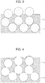
- FIG. 1 is a diagram schematically illustrating a polyimide resin-fine particle composite film. Fine particles 1 are dispersed in a polyimide resin portion 2 to thereby form the polyimide resin-fine particle composite film. In the vicinity of a surface of the polyimide resin-fine particle composite film, the polyimide resin portion 2 covers a part of or entire fine particles 1. It should be noted that, since FIG. 1 is a schematic diagram, the fine particles 1 are illustrated in substantially the same diameter; however, the present invention is not limited thereto and the particle diameters of the fine particles 1 can have a distribution.
- removing at least a part of a polyimide resin portion prior to the fine particles removing step means removing any part of the polyimide resin portion 2 in FIG. 1 .
- FIG. 2 illustrates a case in which a relatively small amount of polyimide resin portion is removed; and
- FIG. 3 illustrates a case in which a larger amount of polyimide resin portion is removed.
- the fine particles can also be partially removed.
- the aperture ratio of the porous polyimide resin film as a final product can be increased, compared to a case of not removing the polyimide resin portion.
- FIG. 4 is a diagram schematically illustrating the porous polyimide resin film immediately after the fine particle removing step. Pores 3 formed by disappearance of the fine particles are distributed in the porous polyimide resin film 4. Similarly to FIG. 1 , since FIG. 4 is a schematic diagram, the pores 3 are illustrated in substantially the same diameter; however, the present invention is not limited thereto and the diameters of the pores 3 can have a distribution.
- Removing at least a part of the porous polyimide resin film subsequent to the fine particles removing step means removing any part of the porous polyimide resin film 4 in FIG. 4 .
- FIG. 5 illustrates a case in which a relatively small amount of porous polyimide resin film is removed
- FIG. 6 illustrates a case in which a larger amount of porous polyimide resin film is removed.
- the pores can be made so as to interconnect with each other, by removing the porous polyimide resin film between adjacent pores.
- the aperture ratio of the porous polyimide resin film as a final product can be increased, compared to a case of not removing.
- the above mentioned step of removing at least a part of the polyimide resin portion, or the step of removing at least a part of the porous polyimide resin film can be performed by a normal chemical etching method, physical removal method, or a combination thereof.
- a treatment with chemical etching solution such as inorganic alkali solution or organic alkali solution can be exemplified.
- the inorganic alkali solution is preferable.
- the inorganic alkali solution hydrazine solution containing hydrazine hydrate and ethylenediamine; solution of alkali metal hydroxides such as potassium hydroxide, sodium hydroxide, sodium carbonate, sodium silicate, sodium metasilicate; ammonia solution; etching solution composed primarily of hydroxylation alkali, hydrazine and 1,3-dimethyl-2-imidazolidinone can be exemplified.
- organic alkali solution primary amines such as ethylamine and n-propylamine; secondary amines such as diethylamine and di-n-butylamine; tertiary amines such as triethylamine and methyldiethylamine; alcohol amines such as dimethylethanolamine and triethanolamine; quaternary ammonium salts such as tetramethylammonium hydroxide and tetraethylammonium hydroxide; and alkaline solution of cyclic amines such as pyrrol and piperidine, can be exemplified.
- primary amines such as ethylamine and n-propylamine
- secondary amines such as diethylamine and di-n-butylamine
- tertiary amines such as triethylamine and methyldiethylamine
- alcohol amines such as dimethylethanolamine and triethanolamine
- quaternary ammonium salts such as
- Pure water and alcohols can be selected as appropriate as a solvent for the above mentioned solutions.
- a solution with an appropriate amount of surfactant can also be used.
- Alkali concentration is for example 0.01 to 20% by mass.
- etching by plasma oxygen, argon
- corona discharge a method of dispersing abrasives (e.g., alumina (hardness 9)) in liquid and spraying onto a surface of the polyimide resin-fine particle composite film or the porous polyimide resin film at a rate of 30 to 100 m/s to treat the surface of the polyimide resin-fine particle composite film or the porous polyimide resin film
- abrasives e.g., alumina (hardness 9)
- the above described method is applicable to either of the polyimide resin removing steps prior to and subsequent to the fine particle removing step, and is therefore preferable. It should be noted that, in a case of performing chemical etching after the fine particle removing step, the aperture ratio can be increased by increasing the size of interconnected pores (pores that are formed where the fine particles were adjacent) in the porous polyimide resin film.
- a method of: pressure bonding a target surface onto a mount film (for example, a polyester film such as a PET film) being wetted with liquid; drying or not drying; and then peeling the porous polyimide resin film from the mount film can also be employed. Due to liquid surface tension or electrostatic adhesive force, a porous polyimide resin film is torn off from a mount film under conditions in which only the face of the porous polyimide resin film was left on the mount film. In this method, the configuration of the porous polyimide resin film is as illustrated by the schematic diagram of FIG. 5 .
- the porous polyimide resin film produced by the above described production method according to the present invention is preferable for having a further increased aperture ratio, and, if employed as a separator in a lithium-ion battery for example, allowing downsizing of the inside of the battery.
- the aperture ratio of the porous polyimide resin film can be evaluated by obtaining Gurley permeability for a thickness of 25 ⁇ m, in other words the number of seconds required for 100 ml air permeating the film, according to JISP8117.
- the porous polyimide resin film of the present invention can be used as the separator for a secondary battery, such as a nickel cadmium battery, a nickel hydrogen battery, a lithium ion secondary battery, and a lithium metal secondary battery and is particularly preferably used as the porous separator for a lithium ion secondary battery.
- a secondary battery such as a nickel cadmium battery, a nickel hydrogen battery, a lithium ion secondary battery, and a lithium metal secondary battery and is particularly preferably used as the porous separator for a lithium ion secondary battery.
- the porous polyimide resin film produced by the production method of the present invention can also be used as the separator of a secondary battery, a fuel cell electrolyte film, a film for separating a gas or liquid, or a low dielectric constant material.
- a secondary battery according to the fourth aspect of the present invention is characterized in comprising an electrolytic solution and the separator according to the third aspect being disposed between a negative electrode and a positive electrode.
- the secondary battery of the present invention may be of any type and may have any configuration.
- the present invention can be employed with no particular limitation in known secondary batteries such as nickel cadmium and nickel hydrogen batteries as well as a lithium ion secondary battery, as long as the battery has a configuration in which a battery element including a positive electrode, a separator, and a negative electrode being laminated in this order so as to satisfy the above-described requirements is impregnated with an electrolytic solution and encapsulated in an outer package.
- the negative electrode of the secondary battery of the present invention can have a structure in which a negative electrode mixture composed of a negative electrode active material, a conductive auxiliary agent, and a binder is formed on a collector.
- a negative electrode active material cadmium hydroxide can be used in nickel cadmium batteries, and a hydrogen-occlusion alloy can be used in nickel hydrogen batteries.
- a material that can be electrochemically doped with lithium can be employed. Examples of such active materials include carbon materials, silicon, aluminum, tin, and Wood's metal.
- Examples of the conductive auxiliary agent constituting the negative electrode include carbon materials such as acetylene black and Ketjen black.
- the binder is composed of an organic polymer, and examples thereof include polyvinylidene fluoride and carboxymethyl cellulose.
- the collector can be, for example, copper foil, stainless steel foil, or nickel foil.
- the positive electrode can have a structure in which a positive electrode mixture composed of a positive electrode active material, a conductive auxiliary agent, and a binder is formed on a collector.
- the positive electrode active material can be nickel hydroxide in nickel cadmium batteries and can be nickel hydroxide or nickel oxyhydroxide in nickel hydrogen batteries.
- examples of the positive electrode active material include lithium-containing transition metal oxides, specifically, LiCoO 2 , LiNiO 2 , LiMn 0.5 Ni 0.5 O 2 , LiCo 1/3 Ni 1/3 Mn 1/3 O 2 , LiMn 2 O 4 , LiFePO 4 , LiCo 0.5 Ni 0.5 O 2 , and LiAl 0.25 Ni 0.75 O 2 .
- Examples of the conductive auxiliary agent include carbon materials such as acetylene black and Ketjen black.
- the binder is an organic polymer, and examples thereof include polyvinylidene fluoride.
- the collector can be, for example, aluminum foil, stainless steel foil, or titanium foil.
- the electrolytic solution in, for example, a nickel cadmium battery or a nickel hydrogen battery is a potassium hydroxide solution.
- the electrolytic solution in a lithium ion secondary battery is composed by dissolving a lithium salt in a non-aqueous solvent.
- the lithium salt include LiPF 6 , LiBF 4 and LiClO 4 .
- the non-aqueous solvent include propylene carbonate, ethylene carbonate, dimethyl carbonate, diethyl carbonate, ethyl methyl carbonate, g-butyrolactone, and vinylene carbonate. These solvents may be used alone or as a mixture.
- Examples of the outer package material include metal cans and aluminum laminate packs.
- the shape of the battery is, for example, a rectangular shape, a cylindrical shape, or a coin shape; however, the separator of the present invention can be suitably applied to any shape.
- Polyamide acid solution was obtained by blending 13.25 g of the polyamide acid and 30 g of the organic solvent (1). 75 g of silica (2) as the fine particles was added to the polyamide acid solution thus obtained to prepare a first varnish. It should be noted that a volume ratio of the polyamide acid and the silica (2) in the first varnish was 22:78 (a mass ratio is 15:85).
- Polyamide acid solution was obtained by blending 13.25 g of the polyamide acid and 30 g of the organic solvent (1). 53 g of silica (1) as the fine particles was added to the polyamide acid solution thus obtained to prepare a second varnish. It should be noted that a volume ratio of the polyamide acid and the silica (1) in the second varnish was 28:72 (a mass ratio is 20:80).
- a film of the second varnish was formed on a glass plate with an applicator.
- An uncalcined composite film having a thickness of 25 ⁇ m was produced by pre-baking at 70°C for 5 minutes.
- the uncalcined composite film was peeled from the substrate and dried to obtain an uncalcined composite film (1).
- the uncalcined composite film (1) was heated (post-baking) at 320°C for about 15 minutes, to complete imidization and obtain a polyimide-fine particle composite film (1).
- the polyimide-fine particle composite film (1) thus obtained was immersed in 10% HF solution for 10 minutes to remove the fine particles contained in the film, washed with water and dried, to obtain a porous polyimide film (1).
- a film of the first varnish was formed on a glass plate with an applicator, and then baked at 70°C for 1 minute, to obtain a first uncalcined composite film of about 2 ⁇ m in thickness. Subsequently, a second uncalcined composite film was formed using the second varnish on the first uncalcined composite film and pre-baked at 70°C for 5 minutes, to obtain a two-layered uncalcined composite film (2) of about 25 ⁇ m in total thickness.
- the uncalcined composite film (2) was heated (post-baking) at 320°C for about 15 minutes, to complete imidization and obtain a polyimide-fine particle composite film (2).
- the polyimide-fine particle composite film (2) thus obtained was immersed in 10% HF solution for 10 minutes to remove the fine particles contained in the film, washed with water and dried, to obtain a porous polyimide film (2).
- the porous polyimide film (2) thus obtained was subjected to a comparison between different chemical etching conditions, using an aqueous solution of tetraalkylammonium hydroxide (TMAH) or NaOH solution, according to Table 1 below.
- TMAH tetraalkylammonium hydroxide
- NaOH NaOH
- TMAH TMAH
- NaOH 50% by mass aqueous solution of methanol
- porous polyimide films (1) and (2) obtained above were subjected to chemical etching according to Table 1 below, employing the NaOH containing etching solution, which had exhibited, among the results of Examples 1 to 8, superior form change of pores on the surface upon removal of a part of the porous polyimide film; and then samples of 25 ⁇ m in thickness were cut therefrom in 5 cm squares.
- the time for 100 mL of air passing through the sample was measured with a Gurley densometer (manufactured by Toyo Seiki Co., Ltd.) in accordance with JIS P 8117. Results are also shown in Table 1.
- FIG. 7 shows that a part of the porous polyimide film is removed and the pore shape on the surface changes as a result of chemical etching.
- the Gurley permeability of the porous polyimide film in Table 1 shows that the time required for 100 ml of air to pass therethrough was substantially reduced as the chemical etching proceeded, and communicability between a foreside and a backside of the porous polyimide film was improved. From a relationship between the permeation time and the thickness change, the improvement in the permeability by the chemical etching is thought to result not only from a reduction in thickness, but also mainly from an increase in aperture ratio.
- a porous polyimide film was prepared in a similar way to [Preparation of varnish] to [Formation of porous polyimide film] described with respect to the porous polyimide film (2).
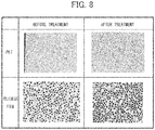
- the porous polyimide film washed with water in a wet state was placed on a polyethylene terephthalate (PET) film and baked. Since a surface layer of the porous polyimide film was electrostatically adhered to the PET film, by subsequently peeling the porous polyimide film thus dried from the PET film, only the surface layer remained on the PET film.
- PET polyethylene terephthalate
- a face peeled from the PET film is the film formed by the first varnish (a negative electrode side when used as a separator for a lithium-ion battery).
- FIG. 8 shows the surface of the PET film before and after this treatment. The remaining segments of the porous polyimide film surface layer can be observed on the surface of the PET film after the treatment.
- tetracarboxylic dianhydride 6.5 g of tetracarboxylic dianhydride, 6.7 g of diamine, and 30 g of the organic solvent (1) were put into a separable flask equipped with a stirrer, a stirring blade, a reflux condenser, and a nitrogen gas inlet tube. Nitrogen was introduced into the flask through the nitrogen gas introduction tube and a nitrogen atmosphere was provided in the flask. Subsequently, the tetracarboxylic dianhydride and the diamine were reacted at 50°C for 20 hours by stirring the contents of the flask to prepare a polyamide acid solution.
- a second varnish in which a volume ratio is 28:72 (mass ratio is 20:80) was prepared in a similar way to [Preparation of varnish - 3], except that 53 g of silica (1) having an average particle diameter of 700 nm was added to the resulting polyamide acid solution.
- a film of the first varnish was formed on a glass plate with an applicator, and then baked at 70°C for 1 minute, to obtain a first uncalcined composite film of about 1 ⁇ m in thickness. Subsequently, a second uncalcined composite film was formed using the second varnish on the first uncalcined composite film and pre-baked at 70°C for 5 minutes, to obtain a two-layered uncalcined composite film (2) of about 20 ⁇ m in total thickness.
- the uncalcined composite film was peeled off from the substrate, the release agent was then removed with ethanol, and a heat treatment was performed at 320°C for 15 minutes to complete imidization and obtain a polyimide-fine particle composite film.
- the polyimide-fine particle composite film was immersed in a 10% HF solution for 10 minutes to remove the fine particles contained in the film.
- Alkaline etching solution was prepared by diluting 2.38% by mass of an aqueous solution of TMAH with 50% by mass of an aqueous solution of methanol, to 1.04%. A part of the polyimide surface was removed by immersing the porous polyimide film in this etching solution. Permeability of the porous polyimide film thus obtained was 63 seconds.
- a porous polyimide film was formed as in Example 14 except that the varnish was prepared by using a dispersant in an amount of 10 parts by weight based on 100 parts by weight of silica. Permeability of the porous polyimide film thus obtained was 60 seconds.
- Example 15 with the dispersant shows a shorter permeation time than Example 14 without the dispersant, and therefore improvement in interconnectivity between pores.
- the strength of the film did not deteriorate even after the chemical etching, and the film had good handleability.
- the separator was used such that a surface thereof with the layer which had been produced by using the first varnish faced the negative electrode.
- the batteries were used as Examples B1 and B2.
- the charge-discharge characteristics were evaluated by charging each coin battery for evaluation at a current density of 2.2 mAh (1C) up to 4.1 V (CC-CV operation) and then discharging the battery at a current density of 2.2 mAh (1C) or 3C down to 2.5 V (CC operation), in a thermostatic chamber.
- Table 3 shows the results.
- the values shown in parentheses are the electrostatic capacity retention ratios (%) at a rate of 3C when the capacity at 1C is defined as 100%.
- a nickel-cobalt-manganese ternary positive electrode and an artificial graphite negative electrode were used as the electrodes, and arranged such that the surface of the layer formed of the first varnish was in contact with the negative electrode.
- monolayer laminate cell batteries were prepared similarly to the above except that a commercially available polyethylene-based (PE-based) or cellulose-based separator was used. These batteries were used as Comparative Examples B1 and B2.
- the PE-based separator being used had an average pore diameter of 80 nm, a thickness of 20 ⁇ m, an air permeability of 270 seconds, and a porosity of 42%; and the cellulose-based separator being used had an average pore diameter of 3000 nm, a thickness of 25 ⁇ m, an air permeability of 135 seconds, and a porosity of 70%.
- the potential change by lithium occlusion was measured with a charge-discharge measuring apparatus.
- the battery was charged up to 4.2 V at a charging speed of 0.2C at 25°C, and after a pause of 10 minutes, was then discharged at a discharging speed of 2C down to a voltage range of 2.7 V. After the discharge, a pause of 10 minutes was taken.
- the battery was evaluated for the Ah utilization rate and Wh utilization rate (energy retention ratio) during this process. Results are shown in Table 3.
- the separator used in each battery was evaluated for the heat resistance using a soldering iron of about 250°C according to the following criteria:
- a crushing test was performed by charging a monolayer laminate cell battery at a voltage of 4.2 V and then compressing the battery in a resting state in the direction vertical to the length direction with a round bar having a diameter of 15.8 mm.
- the time when the voltage reduced was determined as the occurrence of internal short-circuit of the battery, and the battery was evaluated by the pressure at the time of the occurrence of the internal short-circuit.
- the amount of reduction in voltage 5 seconds after the time of the reduction of the voltage was defined as ⁇ V (V). A higher value of the pressure is preferred, and a lower reduction in voltage is preferred.
- Example B1 and Comparative Examples B1 and B2 the potential change due to lithium occlusion was measured by using a charge-discharge measuring apparatus.
- a charge-discharge measuring apparatus At a temperature of 0°C and a charging speed of 1C, an Ah efficiency and a capacity retention ratio at a fifth cycle (ratio to the electric discharge capacity at a first cycle) were obtained under conditions of: charging CCCV: 4.2 V; CV: 1 hour; discharge: 2.7 V. Results are shown in Table 4.
- the negative electrode was taken out from the battery after completion of the above described charge-discharge characteristics evaluation test, and a surface thereof was observed. Statuses of dendrite generation on the negative electrode surfaces are shown in Table 4.
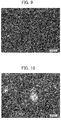
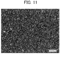
- the negative electrode surfaces of Example B1, Comparative Example B1 and Comparative Example B2 were enlarged 500 times and observed with an optical microscope. The images are shown in FIGS. 9 to 11 .
- Example B1 employing the separator of the present invention was superior in heat resistance and performance in the crushing test to Comparative Examples B1 and B2 employing commercially available separators.
- FIGS. 9 to 11 are pictures of surfaces of negative electrodes taken out from batteries of Example B1 and Comparative Examples B1 and B2 after completion of the above described charge-discharge characteristics evaluation test.
- White bright spots due to generation of lithium dendrite were observed on each of these.
- the battery of Example B1 there are only a few bright spots on the negative electrode, showing that lithium dendrite generation due to charge and discharge is effectively suppressed.
- the bright spots on the negative electrodes taken out from Comparative Examples B1 and B2 are large in size and number. In other words, it can be observed that lithium dendrite generation occurs more frequently in Comparative Examples employing commercially available separators based on polyethylene (PE) or cellulose, compared to a case of using the separator of the present invention.
- PE polyethylene
- Table 4 and FIGS. 9 to 11 show that the battery employing the separator of Example of the present invention can suppress an amount of lithium dendrite generated on a negative electrode surface and provides a superior capacity retention ratio at low temperature, suggesting that an electrical field applied to the separator is homogenized.
- a film of the varnish (5) was formed on a PET film with an applicator.
- An uncalcined composite film having a thickness of approximately 28 ⁇ m was produced by pre-baking at 100°C for 5 minutes.
- the uncalcined composite film was peeled from the substrate and dried to obtain an uncalcined composite film (5), that is a polyamide imide-fine particle composite film (1).
- the solvent had been removed from the uncalcined composite film (5) (polyamide imide-fine particle composite film (1)), the solvent had been removed.
- the uncalcined composite film was not subjected to a calcining step.
- the polyamide imide-fine particle composite film (1) thus obtained was immersed in 10% HF solution for 10 minutes to remove the fine particles contained in the film, washed with water and dried, to obtain a porous polyamide imide film (1).
- porous polyamide imide film (1) thus obtained was subjected to a comparison between different chemical etching conditions, using NaOH solutions described below, according to Table 5 below.
- Table 5 shows that, similarly to the case of the porous polyimide film, even in a case of employing polyamide imide as the polyimide resin, the chemical etching improved Gurley permeability and communicability between a foreside and a backside of the porous polyamide imide film. From a relationship between the permeation time and the thickness change, the improvement in the permeability by the chemical etching is thought to result from not only a reduction in thickness, but also mainly from an increase in aperture ratio as a result of enlargement of openings on the surface and interconnected pores.
Landscapes
- Chemical & Material Sciences (AREA)
- Engineering & Computer Science (AREA)
- Chemical Kinetics & Catalysis (AREA)
- Materials Engineering (AREA)
- Manufacturing & Machinery (AREA)
- General Chemical & Material Sciences (AREA)
- Electrochemistry (AREA)
- Organic Chemistry (AREA)
- Polymers & Plastics (AREA)
- Medicinal Chemistry (AREA)
- Health & Medical Sciences (AREA)
- Inorganic Chemistry (AREA)
- Manufacture Of Porous Articles, And Recovery And Treatment Of Waste Products (AREA)
- Compositions Of Macromolecular Compounds (AREA)
- Cell Separators (AREA)
- Separation Using Semi-Permeable Membranes (AREA)
- Macromolecular Compounds Obtained By Forming Nitrogen-Containing Linkages In General (AREA)
Claims (4)
- Procédé de production d'un film poreux en résine de polyimide comprenant l'élimination de particules fines à partir d'un film composite de résine de polyimide-particules fines pour ainsi obtenir un film poreux en résine de polyimide,
dans lequel :- le procédé comprend soit une étape d'élimination d'au moins une partie d'une portion de résine de polyimide du film composite de résine de polyimide-particules fines avant d'éliminer les particules fines, soit une étape d'élimination d'au moins une partie du film poreux en résine de polyimide après l'élimination des particules fines,- l'étape d'élimination d'au moins une partie de la portion de résine de polyimide est effectuée par un procédé de gravure chimique, ou une combinaison d'un procédé de gravure chimique et d'un procédé d'élimination physique,- l'étape d'élimination d'au moins une partie du film poreux en résine de polyimide est effectuée par un procédé de gravure chimique, un procédé d'élimination physique, ou une combinaison de ceux-ci, et- le diamètre moyen des particules fines est de 100 à 2000 nm. - Procédé de production d'un film poreux en résine de polyimide selon la revendication 1, dans lequel au moins une partie de la portion de résine de polyimide ou au moins une partie du film poreux en résine de polyimide est éliminée par gravure chimique.
- Procédé de production d'un film poreux en résine de polyimide selon l'une quelconque des revendications 1 à 2, dans lequel le film poreux en résine de polyimide après l'élimination d'au moins une partie de la portion de résine de polyimide ou d'au moins une partie du film poreux en résine de polyimide présente une épaisseur de 25 µm et une perméabilité Gurley (JISP8117) d'au plus 120 secondes avec une quantité d'air diffusée de 100 ml.
- Procédé de production d'un film poreux en résine de polyimide selon l'une quelconque des revendications 1 à 3, dans lequel la résine de polyimide est un polyimide ou un polyamide imide
Applications Claiming Priority (3)
| Application Number | Priority Date | Filing Date | Title |
|---|---|---|---|
| JP2013165407 | 2013-08-08 | ||
| JP2014073987 | 2014-03-31 | ||
| PCT/JP2014/070769 WO2015020101A1 (fr) | 2013-08-08 | 2014-08-06 | Procédé de production pour un film poreux en résine polyimide, film poreux en résine polyimide et séparateur faisant appel à celui-ci |
Publications (3)
| Publication Number | Publication Date |
|---|---|
| EP3029093A1 EP3029093A1 (fr) | 2016-06-08 |
| EP3029093A4 EP3029093A4 (fr) | 2016-06-08 |
| EP3029093B1 true EP3029093B1 (fr) | 2018-11-14 |
Family
ID=52461432
Family Applications (1)
| Application Number | Title | Priority Date | Filing Date |
|---|---|---|---|
| EP14835087.9A Active EP3029093B1 (fr) | 2013-08-08 | 2014-08-06 | Procédé de production pour un film poreux en résine polyimide, film poreux en résine polyimide et séparateur faisant appel à celui-ci |
Country Status (7)
| Country | Link |
|---|---|
| US (1) | US9683087B2 (fr) |
| EP (1) | EP3029093B1 (fr) |
| JP (1) | JP6058142B2 (fr) |
| KR (1) | KR101690916B1 (fr) |
| CN (1) | CN105452356B (fr) |
| TW (1) | TWI628213B (fr) |
| WO (1) | WO2015020101A1 (fr) |
Families Citing this family (32)
| Publication number | Priority date | Publication date | Assignee | Title |
|---|---|---|---|---|
| CN109608682A (zh) | 2013-04-22 | 2019-04-12 | 东京应化工业株式会社 | 多孔聚酰亚胺膜的制造方法、多孔聚酰亚胺膜和使用了该多孔聚酰亚胺膜的隔板 |
| TWI665024B (zh) * | 2014-06-20 | 2019-07-11 | 日商東京應化工業股份有限公司 | 塗佈裝置及多孔性之醯亞胺系樹脂膜製造系統 |
| TWI701292B (zh) * | 2014-06-20 | 2020-08-11 | 日商東京應化工業股份有限公司 | 醯亞胺系樹脂膜製造系統及醯亞胺系樹脂膜製造方法 |
| TWI673154B (zh) * | 2014-06-20 | 2019-10-01 | 日商東京應化工業股份有限公司 | 多孔性之醯亞胺系樹脂膜製造系統、分隔膜及多孔性之醯亞胺系樹脂膜製造方法 |
| JP6596196B2 (ja) * | 2014-09-05 | 2019-10-23 | 東京応化工業株式会社 | 多孔質膜製造用ワニスの製造方法 |
| US10576432B2 (en) | 2015-02-06 | 2020-03-03 | Tokyo Ohka Kogyo Co., Ltd. | Polyimide and/or polyamideimide porous body and method for manufacturing same, method for separation and/or adsorption, separation material, adsorption material, filter media, laminate, and filter device |
| JP6701834B2 (ja) * | 2015-03-26 | 2020-05-27 | 富士ゼロックス株式会社 | 樹脂粒子分散ポリイミド前駆体溶液の製造方法、樹脂粒子分散ポリイミド前駆体溶液、樹脂粒子含有ポリイミドフィルム、多孔質ポリイミドフィルムの製造方法、及び多孔質ポリイミドフィルム |
| JP6701833B2 (ja) * | 2015-03-26 | 2020-05-27 | 富士ゼロックス株式会社 | 多孔質ポリイミドフィルムの製造方法、及び多孔質ポリイミドフィルム |
| US9707722B2 (en) * | 2015-03-26 | 2017-07-18 | Fuji Xerox Co., Ltd. | Method for producing porous polyimide film, and porous polyimide film |
| JP6421671B2 (ja) * | 2015-03-26 | 2018-11-14 | 富士ゼロックス株式会社 | 多孔質ポリイミドフィルム |
| JP6441148B2 (ja) * | 2015-03-31 | 2018-12-19 | 東京応化工業株式会社 | 多孔質ポリアミドイミド膜形成用ワニス、多孔質ポリアミドイミド膜並びにそれを用いたセパレータ及び二次電池 |
| CN104742461B (zh) * | 2015-04-16 | 2017-05-24 | 达迈科技股份有限公司 | 低光泽度的双层聚酰亚胺膜及其制造方法 |
| WO2017014147A1 (fr) * | 2015-07-23 | 2017-01-26 | 東京応化工業株式会社 | Membrane poreuse, corps laminé, séparateur pour batterie rechargeable au lithium-ion et procédé de production de membrane poreuse |
| US10865286B2 (en) | 2015-09-04 | 2020-12-15 | Tokyo Ohka Kogyo Co., Ltd. | Method for manufacturing porous membrane |
| JP2017064711A (ja) * | 2015-09-30 | 2017-04-06 | 東京応化工業株式会社 | 濾過フィルター及び濾過方法、並びにリソグラフィー用薬液精製品の製造方法 |
| JP6869680B2 (ja) * | 2015-09-30 | 2021-05-12 | 東京応化工業株式会社 | 濾過フィルター及び濾過方法、並びにリソグラフィー用薬液精製品の製造方法 |
| US10429738B2 (en) * | 2015-09-30 | 2019-10-01 | Tokyo Ohka Kogyo Co., Ltd. | Filtration filter, filtration method, production method of purified liquid chemical product for lithography, and method of forming resist pattern |
| JP6795884B2 (ja) * | 2015-11-10 | 2020-12-02 | 東京応化工業株式会社 | 液体を被精製物とする精製方法、ケイ素化合物含有液を被精製物とする精製方法、シリル化剤薬液、膜形成用材料又は拡散剤組成物の製造方法、フィルターメディア、及び、フィルターデバイス |
| JP6653581B2 (ja) * | 2016-01-18 | 2020-02-26 | 東京応化工業株式会社 | 多孔質膜 |
| JP6835848B2 (ja) * | 2016-08-03 | 2021-02-24 | 東京応化工業株式会社 | 液体の精製方法、及び多孔質膜の製造方法 |
| JP6767048B2 (ja) * | 2016-12-08 | 2020-10-14 | 東京都公立大学法人 | 3次元規則配列マクロポア構造を有するポリイミドセパレータ及びその製造方法 |
| JP6876912B2 (ja) * | 2017-02-24 | 2021-05-26 | 富士フイルムビジネスイノベーション株式会社 | ポリイミド前駆体溶液、及び多孔質ポリイミドフィルムの製造方法 |
| JP6897150B2 (ja) * | 2017-02-24 | 2021-06-30 | 富士フイルムビジネスイノベーション株式会社 | ポリイミド前駆体溶液の製造方法、ポリイミド前駆体溶液、及び多孔質ポリイミドフィルムの製造方法 |
| JP7024225B2 (ja) * | 2017-06-29 | 2022-02-24 | 富士フイルムビジネスイノベーション株式会社 | ポリイミド積層膜、及びポリイミド積層膜の製造方法 |
| WO2019093498A1 (fr) | 2017-11-10 | 2019-05-16 | 旭化成株式会社 | Separateur pour dispositifs de stockage d'électricité et dispositif de stockage d'électricité |
| JP7047415B2 (ja) * | 2018-01-31 | 2022-04-05 | 富士フイルムビジネスイノベーション株式会社 | 多孔質ポリイミド成形体及び多孔質ポリイミド成形体の製造方法 |
| JP7169809B2 (ja) | 2018-08-07 | 2022-11-11 | 東京応化工業株式会社 | イミド系樹脂膜製造システム、イミド系樹脂膜製造方法及びセパレータ製造方法 |
| JP7495788B2 (ja) * | 2018-12-26 | 2024-06-05 | 住友化学株式会社 | ポリイミド系樹脂の製造方法 |
| JP7419815B2 (ja) * | 2019-12-27 | 2024-01-23 | 富士フイルムビジネスイノベーション株式会社 | 多孔質ポリイミドフィルム、二次電池用セパレータ、及び二次電池 |
| CN114085406B (zh) * | 2021-11-03 | 2023-07-18 | 广州明美新能源股份有限公司 | 一种孔径可控的聚酰胺酰亚胺涂覆改性聚烯烃隔离膜及其制备方法与应用 |
| CN116875183B (zh) * | 2023-06-27 | 2024-05-31 | 苏州科丽尔化学有限公司 | 一种电池液冷板涂层及其制备方法 |
| CN120199972B (zh) * | 2025-05-19 | 2025-08-05 | 宁波博雅聚力新材料科技有限公司 | 一种聚酰亚胺微球改性的复合隔膜及其制备方法与应用 |
Family Cites Families (12)
| Publication number | Priority date | Publication date | Assignee | Title |
|---|---|---|---|---|
| JPH11144697A (ja) * | 1997-11-10 | 1999-05-28 | Japan Storage Battery Co Ltd | 非水電解質電池 |
| US6635381B2 (en) * | 2000-05-11 | 2003-10-21 | Wilson Greatbatch Ltd. | Electrochemical lithium ion secondary cell having a scalloped electrode assembly |
| JP2004204119A (ja) * | 2002-12-26 | 2004-07-22 | Mitsubishi Paper Mills Ltd | 多孔質フィルム及びこれを用いた電気化学素子 |
| JP5530178B2 (ja) * | 2007-03-19 | 2014-06-25 | イビデン株式会社 | 多孔性ポリイミド |
| JP2008231369A (ja) * | 2007-03-23 | 2008-10-02 | Yamaha Corp | 多孔板吸音体の製造方法 |
| EP2201628B1 (fr) | 2007-08-21 | 2015-02-18 | A123 Systems, Inc. | Séparateur pour pile électrochimique et procédé pour sa fabrication |
| JP2009177071A (ja) * | 2008-01-28 | 2009-08-06 | Raytech Kk | ポリイミドフィルム回路基板およびその製造方法 |
| JP2010195899A (ja) * | 2009-02-24 | 2010-09-09 | Sumitomo Chemical Co Ltd | 多孔質フィルムの製造方法、多孔質フィルム、積層多孔質フィルムの製造方法、積層多孔質フィルムおよび電池用セパレータ |
| JP5900868B2 (ja) * | 2009-11-24 | 2016-04-06 | 公立大学法人首都大学東京 | 多孔質ポリイミドおよびその製造方法 |
| JP5605566B2 (ja) | 2010-11-18 | 2014-10-15 | 公立大学法人首都大学東京 | 多孔質ポリイミド膜の製造方法 |
| JP2013109842A (ja) * | 2011-11-17 | 2013-06-06 | Ibiden Co Ltd | リチウムイオン電池用セパレータの製造方法 |
| CN102530843B (zh) * | 2012-01-20 | 2014-08-13 | 中国科学院上海技术物理研究所 | 一种疏松化聚酰亚胺红外吸收薄膜的制备方法 |
-
2014
- 2014-08-06 CN CN201480044288.0A patent/CN105452356B/zh active Active
- 2014-08-06 WO PCT/JP2014/070769 patent/WO2015020101A1/fr not_active Ceased
- 2014-08-06 JP JP2015530925A patent/JP6058142B2/ja active Active
- 2014-08-06 TW TW103127189A patent/TWI628213B/zh active
- 2014-08-06 EP EP14835087.9A patent/EP3029093B1/fr active Active
- 2014-08-06 KR KR1020167005043A patent/KR101690916B1/ko active Active
- 2014-08-06 US US14/909,716 patent/US9683087B2/en active Active
Non-Patent Citations (1)
| Title |
|---|
| None * |
Also Published As
| Publication number | Publication date |
|---|---|
| CN105452356A (zh) | 2016-03-30 |
| TW201520250A (zh) | 2015-06-01 |
| EP3029093A1 (fr) | 2016-06-08 |
| KR101690916B1 (ko) | 2016-12-28 |
| CN105452356B (zh) | 2018-02-09 |
| JPWO2015020101A1 (ja) | 2017-03-02 |
| TWI628213B (zh) | 2018-07-01 |
| US20160185932A1 (en) | 2016-06-30 |
| KR20160030320A (ko) | 2016-03-16 |
| JP6058142B2 (ja) | 2017-01-11 |
| US9683087B2 (en) | 2017-06-20 |
| EP3029093A4 (fr) | 2016-06-08 |
| WO2015020101A1 (fr) | 2015-02-12 |
Similar Documents
| Publication | Publication Date | Title |
|---|---|---|
| EP3029093B1 (fr) | Procédé de production pour un film poreux en résine polyimide, film poreux en résine polyimide et séparateur faisant appel à celui-ci | |
| EP2990199B1 (fr) | Procédé de production d'un film de polyimide poreux, film de polyimide poreux et séparateur utilisant celui-ci | |
| US11344848B2 (en) | Porous film and method for producing same | |
| EP3113246B1 (fr) | Séparateur poreux pour accumulateurs et accumulateur l'utilisant | |
| US10177357B2 (en) | Method for producing porous polyimide film | |
| US10189968B2 (en) | Varnish for porous polyimide film production and method for producing porous polyimide film using same |
Legal Events
| Date | Code | Title | Description |
|---|---|---|---|
| PUAI | Public reference made under article 153(3) epc to a published international application that has entered the european phase |
Free format text: ORIGINAL CODE: 0009012 |
|
| 17P | Request for examination filed |
Effective date: 20160303 |
|
| A4 | Supplementary search report drawn up and despatched |
Effective date: 20160412 |
|
| AK | Designated contracting states |
Kind code of ref document: A1 Designated state(s): AL AT BE BG CH CY CZ DE DK EE ES FI FR GB GR HR HU IE IS IT LI LT LU LV MC MK MT NL NO PL PT RO RS SE SI SK SM TR |
|
| AX | Request for extension of the european patent |
Extension state: BA ME |
|
| 17Q | First examination report despatched |
Effective date: 20160519 |
|
| DAX | Request for extension of the european patent (deleted) | ||
| STAA | Information on the status of an ep patent application or granted ep patent |
Free format text: STATUS: EXAMINATION IS IN PROGRESS |
|
| GRAP | Despatch of communication of intention to grant a patent |
Free format text: ORIGINAL CODE: EPIDOSNIGR1 |
|
| STAA | Information on the status of an ep patent application or granted ep patent |
Free format text: STATUS: GRANT OF PATENT IS INTENDED |
|
| INTG | Intention to grant announced |
Effective date: 20180621 |
|
| GRAS | Grant fee paid |
Free format text: ORIGINAL CODE: EPIDOSNIGR3 |
|
| GRAA | (expected) grant |
Free format text: ORIGINAL CODE: 0009210 |
|
| STAA | Information on the status of an ep patent application or granted ep patent |
Free format text: STATUS: THE PATENT HAS BEEN GRANTED |
|
| AK | Designated contracting states |
Kind code of ref document: B1 Designated state(s): AL AT BE BG CH CY CZ DE DK EE ES FI FR GB GR HR HU IE IS IT LI LT LU LV MC MK MT NL NO PL PT RO RS SE SI SK SM TR |
|
| REG | Reference to a national code |
Ref country code: CH Ref legal event code: EP Ref country code: AT Ref legal event code: REF Ref document number: 1064739 Country of ref document: AT Kind code of ref document: T Effective date: 20181115 |
|
| REG | Reference to a national code |
Ref country code: DE Ref legal event code: R096 Ref document number: 602014036177 Country of ref document: DE |
|
| REG | Reference to a national code |
Ref country code: IE Ref legal event code: FG4D |
|
| REG | Reference to a national code |
Ref country code: NL Ref legal event code: MP Effective date: 20181114 |
|
| REG | Reference to a national code |
Ref country code: LT Ref legal event code: MG4D |
|
| REG | Reference to a national code |
Ref country code: AT Ref legal event code: MK05 Ref document number: 1064739 Country of ref document: AT Kind code of ref document: T Effective date: 20181114 |
|
| PG25 | Lapsed in a contracting state [announced via postgrant information from national office to epo] |
Ref country code: NO Free format text: LAPSE BECAUSE OF FAILURE TO SUBMIT A TRANSLATION OF THE DESCRIPTION OR TO PAY THE FEE WITHIN THE PRESCRIBED TIME-LIMIT Effective date: 20190214 Ref country code: BG Free format text: LAPSE BECAUSE OF FAILURE TO SUBMIT A TRANSLATION OF THE DESCRIPTION OR TO PAY THE FEE WITHIN THE PRESCRIBED TIME-LIMIT Effective date: 20190214 Ref country code: FI Free format text: LAPSE BECAUSE OF FAILURE TO SUBMIT A TRANSLATION OF THE DESCRIPTION OR TO PAY THE FEE WITHIN THE PRESCRIBED TIME-LIMIT Effective date: 20181114 Ref country code: LT Free format text: LAPSE BECAUSE OF FAILURE TO SUBMIT A TRANSLATION OF THE DESCRIPTION OR TO PAY THE FEE WITHIN THE PRESCRIBED TIME-LIMIT Effective date: 20181114 Ref country code: LV Free format text: LAPSE BECAUSE OF FAILURE TO SUBMIT A TRANSLATION OF THE DESCRIPTION OR TO PAY THE FEE WITHIN THE PRESCRIBED TIME-LIMIT Effective date: 20181114 Ref country code: HR Free format text: LAPSE BECAUSE OF FAILURE TO SUBMIT A TRANSLATION OF THE DESCRIPTION OR TO PAY THE FEE WITHIN THE PRESCRIBED TIME-LIMIT Effective date: 20181114 Ref country code: ES Free format text: LAPSE BECAUSE OF FAILURE TO SUBMIT A TRANSLATION OF THE DESCRIPTION OR TO PAY THE FEE WITHIN THE PRESCRIBED TIME-LIMIT Effective date: 20181114 Ref country code: IS Free format text: LAPSE BECAUSE OF FAILURE TO SUBMIT A TRANSLATION OF THE DESCRIPTION OR TO PAY THE FEE WITHIN THE PRESCRIBED TIME-LIMIT Effective date: 20190314 Ref country code: AT Free format text: LAPSE BECAUSE OF FAILURE TO SUBMIT A TRANSLATION OF THE DESCRIPTION OR TO PAY THE FEE WITHIN THE PRESCRIBED TIME-LIMIT Effective date: 20181114 |
|
| PG25 | Lapsed in a contracting state [announced via postgrant information from national office to epo] |
Ref country code: GR Free format text: LAPSE BECAUSE OF FAILURE TO SUBMIT A TRANSLATION OF THE DESCRIPTION OR TO PAY THE FEE WITHIN THE PRESCRIBED TIME-LIMIT Effective date: 20190215 Ref country code: RS Free format text: LAPSE BECAUSE OF FAILURE TO SUBMIT A TRANSLATION OF THE DESCRIPTION OR TO PAY THE FEE WITHIN THE PRESCRIBED TIME-LIMIT Effective date: 20181114 Ref country code: PT Free format text: LAPSE BECAUSE OF FAILURE TO SUBMIT A TRANSLATION OF THE DESCRIPTION OR TO PAY THE FEE WITHIN THE PRESCRIBED TIME-LIMIT Effective date: 20190314 Ref country code: SE Free format text: LAPSE BECAUSE OF FAILURE TO SUBMIT A TRANSLATION OF THE DESCRIPTION OR TO PAY THE FEE WITHIN THE PRESCRIBED TIME-LIMIT Effective date: 20181114 Ref country code: AL Free format text: LAPSE BECAUSE OF FAILURE TO SUBMIT A TRANSLATION OF THE DESCRIPTION OR TO PAY THE FEE WITHIN THE PRESCRIBED TIME-LIMIT Effective date: 20181114 Ref country code: NL Free format text: LAPSE BECAUSE OF FAILURE TO SUBMIT A TRANSLATION OF THE DESCRIPTION OR TO PAY THE FEE WITHIN THE PRESCRIBED TIME-LIMIT Effective date: 20181114 |
|
| PG25 | Lapsed in a contracting state [announced via postgrant information from national office to epo] |
Ref country code: PL Free format text: LAPSE BECAUSE OF FAILURE TO SUBMIT A TRANSLATION OF THE DESCRIPTION OR TO PAY THE FEE WITHIN THE PRESCRIBED TIME-LIMIT Effective date: 20181114 Ref country code: DK Free format text: LAPSE BECAUSE OF FAILURE TO SUBMIT A TRANSLATION OF THE DESCRIPTION OR TO PAY THE FEE WITHIN THE PRESCRIBED TIME-LIMIT Effective date: 20181114 Ref country code: IT Free format text: LAPSE BECAUSE OF FAILURE TO SUBMIT A TRANSLATION OF THE DESCRIPTION OR TO PAY THE FEE WITHIN THE PRESCRIBED TIME-LIMIT Effective date: 20181114 Ref country code: CZ Free format text: LAPSE BECAUSE OF FAILURE TO SUBMIT A TRANSLATION OF THE DESCRIPTION OR TO PAY THE FEE WITHIN THE PRESCRIBED TIME-LIMIT Effective date: 20181114 |
|
| REG | Reference to a national code |
Ref country code: DE Ref legal event code: R097 Ref document number: 602014036177 Country of ref document: DE |
|
| PG25 | Lapsed in a contracting state [announced via postgrant information from national office to epo] |
Ref country code: SK Free format text: LAPSE BECAUSE OF FAILURE TO SUBMIT A TRANSLATION OF THE DESCRIPTION OR TO PAY THE FEE WITHIN THE PRESCRIBED TIME-LIMIT Effective date: 20181114 Ref country code: SM Free format text: LAPSE BECAUSE OF FAILURE TO SUBMIT A TRANSLATION OF THE DESCRIPTION OR TO PAY THE FEE WITHIN THE PRESCRIBED TIME-LIMIT Effective date: 20181114 Ref country code: RO Free format text: LAPSE BECAUSE OF FAILURE TO SUBMIT A TRANSLATION OF THE DESCRIPTION OR TO PAY THE FEE WITHIN THE PRESCRIBED TIME-LIMIT Effective date: 20181114 Ref country code: EE Free format text: LAPSE BECAUSE OF FAILURE TO SUBMIT A TRANSLATION OF THE DESCRIPTION OR TO PAY THE FEE WITHIN THE PRESCRIBED TIME-LIMIT Effective date: 20181114 |
|
| PLBE | No opposition filed within time limit |
Free format text: ORIGINAL CODE: 0009261 |
|
| STAA | Information on the status of an ep patent application or granted ep patent |
Free format text: STATUS: NO OPPOSITION FILED WITHIN TIME LIMIT |
|
| 26N | No opposition filed |
Effective date: 20190815 |
|
| PG25 | Lapsed in a contracting state [announced via postgrant information from national office to epo] |
Ref country code: SI Free format text: LAPSE BECAUSE OF FAILURE TO SUBMIT A TRANSLATION OF THE DESCRIPTION OR TO PAY THE FEE WITHIN THE PRESCRIBED TIME-LIMIT Effective date: 20181114 |
|
| PG25 | Lapsed in a contracting state [announced via postgrant information from national office to epo] |
Ref country code: TR Free format text: LAPSE BECAUSE OF FAILURE TO SUBMIT A TRANSLATION OF THE DESCRIPTION OR TO PAY THE FEE WITHIN THE PRESCRIBED TIME-LIMIT Effective date: 20181114 |
|
| GBPC | Gb: european patent ceased through non-payment of renewal fee |
Effective date: 20190806 |
|
| PG25 | Lapsed in a contracting state [announced via postgrant information from national office to epo] |
Ref country code: LU Free format text: LAPSE BECAUSE OF NON-PAYMENT OF DUE FEES Effective date: 20190806 Ref country code: MC Free format text: LAPSE BECAUSE OF FAILURE TO SUBMIT A TRANSLATION OF THE DESCRIPTION OR TO PAY THE FEE WITHIN THE PRESCRIBED TIME-LIMIT Effective date: 20181114 Ref country code: LI Free format text: LAPSE BECAUSE OF NON-PAYMENT OF DUE FEES Effective date: 20190831 Ref country code: CH Free format text: LAPSE BECAUSE OF NON-PAYMENT OF DUE FEES Effective date: 20190831 |
|
| REG | Reference to a national code |
Ref country code: BE Ref legal event code: MM Effective date: 20190831 |
|
| PG25 | Lapsed in a contracting state [announced via postgrant information from national office to epo] |
Ref country code: IE Free format text: LAPSE BECAUSE OF NON-PAYMENT OF DUE FEES Effective date: 20190806 |
|
| PG25 | Lapsed in a contracting state [announced via postgrant information from national office to epo] |
Ref country code: GB Free format text: LAPSE BECAUSE OF NON-PAYMENT OF DUE FEES Effective date: 20190806 Ref country code: BE Free format text: LAPSE BECAUSE OF NON-PAYMENT OF DUE FEES Effective date: 20190831 |
|
| PG25 | Lapsed in a contracting state [announced via postgrant information from national office to epo] |
Ref country code: CY Free format text: LAPSE BECAUSE OF FAILURE TO SUBMIT A TRANSLATION OF THE DESCRIPTION OR TO PAY THE FEE WITHIN THE PRESCRIBED TIME-LIMIT Effective date: 20181114 |
|
| PG25 | Lapsed in a contracting state [announced via postgrant information from national office to epo] |
Ref country code: HU Free format text: LAPSE BECAUSE OF FAILURE TO SUBMIT A TRANSLATION OF THE DESCRIPTION OR TO PAY THE FEE WITHIN THE PRESCRIBED TIME-LIMIT; INVALID AB INITIO Effective date: 20140806 Ref country code: MT Free format text: LAPSE BECAUSE OF FAILURE TO SUBMIT A TRANSLATION OF THE DESCRIPTION OR TO PAY THE FEE WITHIN THE PRESCRIBED TIME-LIMIT Effective date: 20181114 |
|
| PG25 | Lapsed in a contracting state [announced via postgrant information from national office to epo] |
Ref country code: MK Free format text: LAPSE BECAUSE OF FAILURE TO SUBMIT A TRANSLATION OF THE DESCRIPTION OR TO PAY THE FEE WITHIN THE PRESCRIBED TIME-LIMIT Effective date: 20181114 |
|
| PGFP | Annual fee paid to national office [announced via postgrant information from national office to epo] |
Ref country code: DE Payment date: 20250724 Year of fee payment: 12 |
|
| PGFP | Annual fee paid to national office [announced via postgrant information from national office to epo] |
Ref country code: FR Payment date: 20250723 Year of fee payment: 12 |