EP3029223A1 - Procédé pour protéger un espace contre une explosion - Google Patents
Procédé pour protéger un espace contre une explosion Download PDFInfo
- Publication number
- EP3029223A1 EP3029223A1 EP15197423.5A EP15197423A EP3029223A1 EP 3029223 A1 EP3029223 A1 EP 3029223A1 EP 15197423 A EP15197423 A EP 15197423A EP 3029223 A1 EP3029223 A1 EP 3029223A1
- Authority
- EP
- European Patent Office
- Prior art keywords
- framework
- uprights
- frame
- layer
- tent
- Prior art date
- Legal status (The legal status is an assumption and is not a legal conclusion. Google has not performed a legal analysis and makes no representation as to the accuracy of the status listed.)
- Withdrawn
Links
- 238000004880 explosion Methods 0.000 title claims abstract description 25
- 238000000034 method Methods 0.000 title claims abstract description 17
- 239000004744 fabric Substances 0.000 claims abstract description 36
- 229910010272 inorganic material Inorganic materials 0.000 claims description 2
- 239000011147 inorganic material Substances 0.000 claims description 2
- 229910000831 Steel Inorganic materials 0.000 description 11
- 239000010959 steel Substances 0.000 description 11
- 230000002349 favourable effect Effects 0.000 description 10
- 239000007789 gas Substances 0.000 description 4
- 230000000694 effects Effects 0.000 description 3
- 239000000835 fiber Substances 0.000 description 3
- OKTJSMMVPCPJKN-UHFFFAOYSA-N Carbon Chemical compound [C] OKTJSMMVPCPJKN-UHFFFAOYSA-N 0.000 description 2
- 238000004873 anchoring Methods 0.000 description 2
- 239000004760 aramid Substances 0.000 description 2
- 229920003235 aromatic polyamide Polymers 0.000 description 2
- 229910052799 carbon Inorganic materials 0.000 description 2
- 238000010276 construction Methods 0.000 description 2
- 239000002184 metal Substances 0.000 description 2
- 239000011490 mineral wool Substances 0.000 description 2
- 239000000203 mixture Substances 0.000 description 2
- 239000000126 substance Substances 0.000 description 2
- 239000004677 Nylon Substances 0.000 description 1
- 238000005452 bending Methods 0.000 description 1
- 239000002360 explosive Substances 0.000 description 1
- 230000009970 fire resistant effect Effects 0.000 description 1
- 239000003365 glass fiber Substances 0.000 description 1
- 238000007689 inspection Methods 0.000 description 1
- 238000009434 installation Methods 0.000 description 1
- 239000004761 kevlar Substances 0.000 description 1
- 238000012423 maintenance Methods 0.000 description 1
- 229920001778 nylon Polymers 0.000 description 1
- 210000000056 organ Anatomy 0.000 description 1
- 239000004576 sand Substances 0.000 description 1
- 238000009423 ventilation Methods 0.000 description 1
Images




Classifications
-
- E—FIXED CONSTRUCTIONS
- E04—BUILDING
- E04H—BUILDINGS OR LIKE STRUCTURES FOR PARTICULAR PURPOSES; SWIMMING OR SPLASH BATHS OR POOLS; MASTS; FENCING; TENTS OR CANOPIES, IN GENERAL
- E04H9/00—Buildings, groups of buildings or shelters adapted to withstand or provide protection against abnormal external influences, e.g. war-like action, earthquake or extreme climate
- E04H9/04—Buildings, groups of buildings or shelters adapted to withstand or provide protection against abnormal external influences, e.g. war-like action, earthquake or extreme climate against air-raid or other war-like actions
- E04H9/06—Structures arranged in or forming part of buildings
-
- F—MECHANICAL ENGINEERING; LIGHTING; HEATING; WEAPONS; BLASTING
- F42—AMMUNITION; BLASTING
- F42D—BLASTING
- F42D5/00—Safety arrangements
- F42D5/04—Rendering explosive charges harmless, e.g. destroying ammunition; Rendering detonation of explosive charges harmless
- F42D5/045—Detonation-wave absorbing or damping means
-
- F—MECHANICAL ENGINEERING; LIGHTING; HEATING; WEAPONS; BLASTING
- F42—AMMUNITION; BLASTING
- F42D—BLASTING
- F42D5/00—Safety arrangements
- F42D5/04—Rendering explosive charges harmless, e.g. destroying ammunition; Rendering detonation of explosive charges harmless
- F42D5/045—Detonation-wave absorbing or damping means
- F42D5/05—Blasting mats
-
- G—PHYSICS
- G07—CHECKING-DEVICES
- G07F—COIN-FREED OR LIKE APPARATUS
- G07F19/00—Complete banking systems; Coded card-freed arrangements adapted for dispensing or receiving monies or the like and posting such transactions to existing accounts, e.g. automatic teller machines
- G07F19/20—Automatic teller machines [ATMs]
- G07F19/207—Surveillance aspects at ATMs
-
- G—PHYSICS
- G07—CHECKING-DEVICES
- G07F—COIN-FREED OR LIKE APPARATUS
- G07F19/00—Complete banking systems; Coded card-freed arrangements adapted for dispensing or receiving monies or the like and posting such transactions to existing accounts, e.g. automatic teller machines
- G07F19/20—Automatic teller machines [ATMs]
- G07F19/205—Housing aspects of ATMs
Definitions
- the present invention relates to a method for safeguarding a space of a building against an explosion.
- the present invention aims to provide a method that reduces the likelihood of damage and/or the amount of damage.
- a method is characterized in that in the space a frame is provided that is anchored to the building, said frame comprising at least three uprights with upper ends and lower ends, which three uprights are not on a single line, wherein each upright is connected with at least two other uprights of the frame by means of at least two beams, two uprights and two beams connecting said two uprights constitute a framework comprising four framework sections, and at least one layer of ballistic cloth is clamped against the framework sections of a pair of two opposite framework sections in order to form a divider wall.
- the divider wall protects the part of the space behind the divider wall against at least part of the effects of an explosion.
- the ballistic cloth is generally a cloth made of super fibres, such as of carbon fibre, aramid fibre (eg. Kevlar TM ) or nylon super fibre (eg. Dyneema TM ).
- the frame comprises profiles, preferably hollow profiles (understood to also include U-profiles, but preferably profiles having a polygonal cross section such as a rectangular cross section), in order to withstand the bending moments that occurr during an explosion.
- the frame is for instance constructed of steel hollow profiles that are welded together or are connected using bolts. This will generally be done at the site of the building.
- the at least one layer of ballistic cloth is clamped against a second pair of two opposite framework sections for forming said divider wall.
- the second pair of framework sections extends transversely to the previously mentioned pair.
- clamping the at least one layer of ballistic cloth against a framework section is done by using at least one elongated element that is attached in parallel with the framework section to said framework section by means of at least one bolted joint per elongated element.
- the elongated element may advantageously have a curvature, wherein in a position where the curved elongated element is held against the framework section, the distance to the framework section at the location of the bolted joint to be formed is larger than at a distance from that bolted joint to be formed (i.e. before tightening the bolt or nut).
- the convex side will be facing the framework section.
- the elongated element e.g. a metal strip
- the at least one layer of ballistic cloth is provided at a circumferential edge with a string extending parallel to the framework section.
- the ballistic cloth will billow and be pulled out from between the framework section and the elongated element (or any other organ used for clamping, such as an annular-shaped element). Because of this, energy of the explosion will be absorbed.
- the string provides so much thickness that this proces of pulling out will be stopped, thus maintaining the division provided by the at least one layer of ballistic cloth.
- the at least one layer of ballistic cloth is turned back at a circumferential edge and is formed into a hem, and the hem is clamped.
- the increased thickness provides a more even distribution of the forces over the ballistic cloth, and transfer to the framework sections. Furthermore, by using a hem, a cavity for the string can be effectively formed, which makes it even more difficult for the ballistic cloth to be pulled out from the framework following an explosion.
- the frame is provided with at least two further divider walls which each comprise at least one layer of ballistic cloth for forming a tent, which tent at 1 side thereof does not provide a closed divider wall and with that one side is directed toward the façade of the building.
- Such a tent is suitable for accommodating, for instance, an ATM.
- the tent will at least comprise one, preferably at least two and more preferably at least three flexible walls, for instance two sidewalls and the upper side.
- the low weight of the tent makes it possible to fit it into existing buildings.
- the tent At the underside thereof the tent will be substantially sealingly positioned against the floor.
- the tent will also be substantially sealingly positioned against the façade.
- the force of the explosion and the discharge of released gases will take place via the façade. Because of this, the damage to the space in which the tent is located is limited to a large extent.
- the clamping is done against the inner circumference of the framework.
- the cloth can be disassembled from the inside in a simple way, keeping constructional buildings and installations accessible for maintenance and inspections.
- the tent comprises an entrance door.
- This side will generally be in the shape of a non-flexible wall. It is for instance a steel wall provided with a steel door.
- the divider wall is provided with a layer of inorganic material selected from i) fibres, and ii) grains.
- Such a layer offers protection against shaped charges.
- the layer is for instance provided by sand, but preferably by a blanket of glass fibre or rock-wool.
- the thickness of the layer is generally at least 5 cm, preferably at least 8 cm, such as at least 10 cm.
- the frame is anchored with the underside thereof.
- the frame is for instance anchored to the floor, to driving piles or the like.
- the frame is anchored chemically.
- the frame can be anchored in a highly effective way, preferably to the floor.
- Fig. 1 shows part of a building 180 comprising a space 190 to be safeguarded against an explosion, adjacent to a façade 191 which gives access from the outside of the building in order to operate the ATM 192.
- a tent 100 is arranged for protecting the space 190 against an explosion, which tent 100 is anchored to a floor 193 of the space 190.
- the tent 100 comprises divider walls 101 which comprise ballistic cloth.
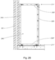
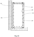
- Fig. 2a-d show the construction of the tent 100 for safeguarding the space 190 against an explosion step by step.
- the tent 100 as visible in Fig. 2d comprises a frame 210 which comprises uprights 220 and beams 230. These are formed out of steel hollow profiles (80 x 80 mm; wall thickness 10 mm).
- the frame 210 comprises four uprights 220 which at the upper side are connected by four upper beams 230' and at the underside of the frame 210 by four lower beams 230".
- the four upper beams 230' constitute an upper frame section 211' with the upper ends of the uprights 220.
- the four lower beams 230" with the lower ends of the uprights 220 constitute a lower frame section 211" with which the frame 210 is anchored to the floor 193.
- holes 294 having a depth of 8 cm are drilled into the floor 193 (side view cross section shown in Fig. 2a ).
- a chemical anchoring composition 295 HIT-HY 200-A + HIT-Z M12; supplier: Hilti The Netherlands B.V., Berkel en Rodenrijs, The Netherlands
- the base plates 221 are welded to the steel uprights 220.
- base plates for instance also one large steel floor plate may be used, whereby the underside of the tent 100 will be connected to the floor 193 over a larger surface and the underlying floor 193 will be loaded more evenly in case of an explosion.
- the uprights 220 have lips 222 for attaching beams 230.
- the framework 240 Distributed over the inner circumference thereof, the framework 240 has threaded holes 243.
- Two opposite upright frameworks 240 are provided with ballistic cloth (aramid), just like the lying framework (i.e. the upper frame section 211'), which ballistic cloth is secured by elongated elements 241 (such as rectangular profiles or slightly curved metal strips) by means of bolts 242 ( Fig. 2c ). This will be elucidated further with reference to Fig. 3 .
- ballistic cloth aramid
- elongated elements 241 such as rectangular profiles or slightly curved metal strips
- Fig. 2d shows a perspective view in which the floor is not shown.
- the ballistic cloth at the side and the upper side are not shown either.
- the upright framework 240 facing away from the façade 191 is provided with a closeable steel door 260. In a closed state this also forms a divider wall 101 of the tent 100.
- the upright framework facing the façade 191 is not provided with ballistic cloth. It resides substantially against the façade.
- the tent 100 preferably is gap-free against the inside of the façade 191.
- the upright framework facing the façade is provided with a steel plate 271 having a thickness of 4 mm, which steel plate has an opening for the ATM 192.
- Fig. 2d in the upper part of the divider wall containing the door 260, two optional openings can be seen.
- the other is for ventilation, wherein a tube will be connected to that opening. If these openings are small, the space 190 remains protected sufficiently.
- Fig. 3 shows in cross section schematically part of the upper frame section 211', which comprises an upper beam 230'.
- the elongated elements 241 are secured to the upper beam 230' by means of bolts 242.
- the four elongated elements 241 are therefore fixed against four framework sections that are a combination of four parts (two pairs of parts) selected from uprights and beams.
- the elongated elements 241 are hollow profiles as well. These are provided with through-holes, through which the bolts 242 are inserted and screwed into the threaded holes 243 for evenly clamping the ballistic cloth 301.
- the ballistic cloth 301 is folded back and secured by stitching, wherein in the hem 303 formed this way a string 302 is introduced.
- the ballistic cloth 301 will give way outwardly (indicated with thin lines), and the ballistic cloth will be pulled between an elongated element and an upper beam (or upright). Because of this, explosion energy is absorbed.
- the string 302, however, provides such a thickness that the ballistic cloth 301 cannot be pulled out of the framework, thus keeping the space 190 protected.
- a layer facing the interior of the space is preferably made of carbon fibre, since this is highly fire-resistant, thus delaying and/or avoiding the spreading of fire from the space 190 in the tent 100 to the space 190.
- Fig. 4 shows a cross section in top plan view of a detail of an alternative tent, wherein a divider wall 101 is provided with a blanket 443 of rockwool having a thickness of 10 cm.
- the blanket 443 is kept in place by means of a steel plate with holes 444 (5 mm thick) of which the side edges 445 are bent and are attached at the uprights 220 and beams 230.
- Such a feature can provide at least some protection against shaped charges.
- Fig. 4 the ballistic cloth 301 is indicated using broken lines, shown in a position it has during an explosion.
Landscapes
- Engineering & Computer Science (AREA)
- Architecture (AREA)
- General Engineering & Computer Science (AREA)
- Business, Economics & Management (AREA)
- Civil Engineering (AREA)
- Environmental & Geological Engineering (AREA)
- Emergency Management (AREA)
- Structural Engineering (AREA)
- Accounting & Taxation (AREA)
- Finance (AREA)
- Physics & Mathematics (AREA)
- General Physics & Mathematics (AREA)
- Tents Or Canopies (AREA)
Applications Claiming Priority (1)
| Application Number | Priority Date | Filing Date | Title |
|---|---|---|---|
| NL2013913A NL2013913B1 (nl) | 2014-12-04 | 2014-12-04 | Werkwijze voor het tegen een explosie beveiligen van een ruimte. |
Publications (1)
| Publication Number | Publication Date |
|---|---|
| EP3029223A1 true EP3029223A1 (fr) | 2016-06-08 |
Family
ID=55027230
Family Applications (1)
| Application Number | Title | Priority Date | Filing Date |
|---|---|---|---|
| EP15197423.5A Withdrawn EP3029223A1 (fr) | 2014-12-04 | 2015-12-02 | Procédé pour protéger un espace contre une explosion |
Country Status (2)
| Country | Link |
|---|---|
| EP (1) | EP3029223A1 (fr) |
| NL (1) | NL2013913B1 (fr) |
Cited By (1)
| Publication number | Priority date | Publication date | Assignee | Title |
|---|---|---|---|---|
| CN109405693A (zh) * | 2018-11-06 | 2019-03-01 | 中国人民解放军军事科学院国防工程研究院 | 一种半埋式可拼装抗爆结构 |
Citations (5)
| Publication number | Priority date | Publication date | Assignee | Title |
|---|---|---|---|---|
| US6244155B1 (en) * | 1999-03-16 | 2001-06-12 | The United States Of America As Represented By The United States Department Of Energy | Explosive parcel containment and blast mitigation container |
| US20060260459A1 (en) * | 2005-04-22 | 2006-11-23 | John Davis | Containment system for and method of blast mitigation in varied environmental settings |
| WO2007073363A2 (fr) * | 2004-12-01 | 2007-06-28 | Life Shield Engineered Systems, Llc | Panneau et systemes et equipement d’isolation de projectiles et procedes de production correspondants |
| WO2012021699A1 (fr) * | 2010-08-13 | 2012-02-16 | J R Innovations LLC | Système de protection anti-explosion pour fenêtre et ses procédés |
| WO2013154609A2 (fr) * | 2011-12-01 | 2013-10-17 | U.S. Army Corps Of Engineers | Système modulaire transportable pour isolation couverte de matériel militaire |
-
2014
- 2014-12-04 NL NL2013913A patent/NL2013913B1/nl active
-
2015
- 2015-12-02 EP EP15197423.5A patent/EP3029223A1/fr not_active Withdrawn
Patent Citations (5)
| Publication number | Priority date | Publication date | Assignee | Title |
|---|---|---|---|---|
| US6244155B1 (en) * | 1999-03-16 | 2001-06-12 | The United States Of America As Represented By The United States Department Of Energy | Explosive parcel containment and blast mitigation container |
| WO2007073363A2 (fr) * | 2004-12-01 | 2007-06-28 | Life Shield Engineered Systems, Llc | Panneau et systemes et equipement d’isolation de projectiles et procedes de production correspondants |
| US20060260459A1 (en) * | 2005-04-22 | 2006-11-23 | John Davis | Containment system for and method of blast mitigation in varied environmental settings |
| WO2012021699A1 (fr) * | 2010-08-13 | 2012-02-16 | J R Innovations LLC | Système de protection anti-explosion pour fenêtre et ses procédés |
| WO2013154609A2 (fr) * | 2011-12-01 | 2013-10-17 | U.S. Army Corps Of Engineers | Système modulaire transportable pour isolation couverte de matériel militaire |
Cited By (2)
| Publication number | Priority date | Publication date | Assignee | Title |
|---|---|---|---|---|
| CN109405693A (zh) * | 2018-11-06 | 2019-03-01 | 中国人民解放军军事科学院国防工程研究院 | 一种半埋式可拼装抗爆结构 |
| CN109405693B (zh) * | 2018-11-06 | 2023-12-26 | 中国人民解放军军事科学院国防工程研究院 | 一种半埋式可拼装抗爆结构 |
Also Published As
| Publication number | Publication date |
|---|---|
| NL2013913B1 (nl) | 2016-10-11 |
Similar Documents
| Publication | Publication Date | Title |
|---|---|---|
| US10961740B2 (en) | Modular security system for above-ground structures | |
| US7637073B2 (en) | Wall structure for protection from ballistic projectiles | |
| CA2973177C (fr) | Chambre forte extensible | |
| US20130019742A1 (en) | Blast protected unit and system | |
| US20230304314A1 (en) | Multi-threat mitigation security apparatus for protecting personnel, assets and critical infrastructure | |
| CA2784607C (fr) | Mur de mat d'amarrage et anti-fragmentation | |
| US9279265B1 (en) | Temporary shelter system | |
| US20110226166A1 (en) | Overhead protection system | |
| US10175156B2 (en) | Pressure test cell | |
| EP3029223A1 (fr) | Procédé pour protéger un espace contre une explosion | |
| EP3314075B1 (fr) | Système de protection à couches multiples | |
| US20160017626A1 (en) | Watchtower | |
| US20120186168A1 (en) | Perforating gun loading and storage facility | |
| US20190153741A1 (en) | Ballistic and fire protection enclosures | |
| RU2338040C1 (ru) | Строительная панель взрывоопасного помещения | |
| GB2534197A (en) | Protective wall | |
| IL167287A (en) | Roof protection device and method | |
| PL224102B1 (pl) | Osłona antywybuchowa kompozytowo-pianowa do ochrony słupów obiektów publicznych |
Legal Events
| Date | Code | Title | Description |
|---|---|---|---|
| PUAI | Public reference made under article 153(3) epc to a published international application that has entered the european phase |
Free format text: ORIGINAL CODE: 0009012 |
|
| AK | Designated contracting states |
Kind code of ref document: A1 Designated state(s): AL AT BE BG CH CY CZ DE DK EE ES FI FR GB GR HR HU IE IS IT LI LT LU LV MC MK MT NL NO PL PT RO RS SE SI SK SM TR |
|
| AX | Request for extension of the european patent |
Extension state: BA ME |
|
| 17P | Request for examination filed |
Effective date: 20161130 |
|
| RBV | Designated contracting states (corrected) |
Designated state(s): AL AT BE BG CH CY CZ DE DK EE ES FI FR GB GR HR HU IE IS IT LI LT LU LV MC MK MT NL NO PL PT RO RS SE SI SK SM TR |
|
| GRAP | Despatch of communication of intention to grant a patent |
Free format text: ORIGINAL CODE: EPIDOSNIGR1 |
|
| RIC1 | Information provided on ipc code assigned before grant |
Ipc: E04B 1/98 20060101ALI20170321BHEP Ipc: E04H 9/06 20060101AFI20170321BHEP Ipc: F42D 5/05 20060101ALI20170321BHEP Ipc: F42D 5/045 20060101ALI20170321BHEP Ipc: G07F 19/00 20060101ALI20170321BHEP |
|
| INTG | Intention to grant announced |
Effective date: 20170411 |
|
| GRAJ | Information related to disapproval of communication of intention to grant by the applicant or resumption of examination proceedings by the epo deleted |
Free format text: ORIGINAL CODE: EPIDOSDIGR1 |
|
| GRAP | Despatch of communication of intention to grant a patent |
Free format text: ORIGINAL CODE: EPIDOSNIGR1 |
|
| INTC | Intention to grant announced (deleted) | ||
| INTG | Intention to grant announced |
Effective date: 20170913 |
|
| STAA | Information on the status of an ep patent application or granted ep patent |
Free format text: STATUS: THE APPLICATION IS DEEMED TO BE WITHDRAWN |
|
| 18D | Application deemed to be withdrawn |
Effective date: 20180124 |