EP3029274B1 - Thermisch gespritztes bonding einer keramikstruktur auf ein substrat - Google Patents
Thermisch gespritztes bonding einer keramikstruktur auf ein substrat Download PDFInfo
- Publication number
- EP3029274B1 EP3029274B1 EP15191109.6A EP15191109A EP3029274B1 EP 3029274 B1 EP3029274 B1 EP 3029274B1 EP 15191109 A EP15191109 A EP 15191109A EP 3029274 B1 EP3029274 B1 EP 3029274B1
- Authority
- EP
- European Patent Office
- Prior art keywords
- feature layer
- ceramic
- protective coating
- ceramic feature
- thermal barrier
- Prior art date
- Legal status (The legal status is an assumption and is not a legal conclusion. Google has not performed a legal analysis and makes no representation as to the accuracy of the status listed.)
- Active
Links
Images



Classifications
-
- F—MECHANICAL ENGINEERING; LIGHTING; HEATING; WEAPONS; BLASTING
- F01—MACHINES OR ENGINES IN GENERAL; ENGINE PLANTS IN GENERAL; STEAM ENGINES
- F01D—NON-POSITIVE DISPLACEMENT MACHINES OR ENGINES, e.g. STEAM TURBINES
- F01D5/00—Blades; Blade-carrying members; Heating, heat-insulating, cooling or antivibration means on the blades or the members
- F01D5/12—Blades
- F01D5/28—Selecting particular materials; Particular measures relating thereto; Measures against erosion or corrosion
- F01D5/288—Protective coatings for blades
-
- B—PERFORMING OPERATIONS; TRANSPORTING
- B32—LAYERED PRODUCTS
- B32B—LAYERED PRODUCTS, i.e. PRODUCTS BUILT-UP OF STRATA OF FLAT OR NON-FLAT, e.g. CELLULAR OR HONEYCOMB, FORM
- B32B3/00—Layered products comprising a layer with external or internal discontinuities or unevennesses, or a layer of non-planar shape; Layered products comprising a layer having particular features of form
- B32B3/10—Layered products comprising a layer with external or internal discontinuities or unevennesses, or a layer of non-planar shape; Layered products comprising a layer having particular features of form characterised by a discontinuous layer, i.e. formed of separate pieces of material
- B32B3/12—Layered products comprising a layer with external or internal discontinuities or unevennesses, or a layer of non-planar shape; Layered products comprising a layer having particular features of form characterised by a discontinuous layer, i.e. formed of separate pieces of material characterised by a layer of regularly- arranged cells, e.g. a honeycomb structure
-
- B—PERFORMING OPERATIONS; TRANSPORTING
- B32—LAYERED PRODUCTS
- B32B—LAYERED PRODUCTS, i.e. PRODUCTS BUILT-UP OF STRATA OF FLAT OR NON-FLAT, e.g. CELLULAR OR HONEYCOMB, FORM
- B32B37/00—Methods or apparatus for laminating, e.g. by curing or by ultrasonic bonding
- B32B37/12—Methods or apparatus for laminating, e.g. by curing or by ultrasonic bonding characterised by using adhesives
-
- B—PERFORMING OPERATIONS; TRANSPORTING
- B32—LAYERED PRODUCTS
- B32B—LAYERED PRODUCTS, i.e. PRODUCTS BUILT-UP OF STRATA OF FLAT OR NON-FLAT, e.g. CELLULAR OR HONEYCOMB, FORM
- B32B7/00—Layered products characterised by the relation between layers; Layered products characterised by the relative orientation of features between layers, or by the relative values of a measurable parameter between layers, i.e. products comprising layers having different physical, chemical or physicochemical properties; Layered products characterised by the interconnection of layers
- B32B7/04—Interconnection of layers
- B32B7/12—Interconnection of layers using interposed adhesives or interposed materials with bonding properties
-
- B—PERFORMING OPERATIONS; TRANSPORTING
- B32—LAYERED PRODUCTS
- B32B—LAYERED PRODUCTS, i.e. PRODUCTS BUILT-UP OF STRATA OF FLAT OR NON-FLAT, e.g. CELLULAR OR HONEYCOMB, FORM
- B32B9/00—Layered products comprising a layer of a particular substance not covered by groups B32B11/00 - B32B29/00
- B32B9/005—Layered products comprising a layer of a particular substance not covered by groups B32B11/00 - B32B29/00 comprising one layer of ceramic material, e.g. porcelain, ceramic tile
-
- B—PERFORMING OPERATIONS; TRANSPORTING
- B32—LAYERED PRODUCTS
- B32B—LAYERED PRODUCTS, i.e. PRODUCTS BUILT-UP OF STRATA OF FLAT OR NON-FLAT, e.g. CELLULAR OR HONEYCOMB, FORM
- B32B9/00—Layered products comprising a layer of a particular substance not covered by groups B32B11/00 - B32B29/00
- B32B9/04—Layered products comprising a layer of a particular substance not covered by groups B32B11/00 - B32B29/00 comprising such particular substance as the main or only constituent of a layer, which is next to another layer of the same or of a different material
- B32B9/041—Layered products comprising a layer of a particular substance not covered by groups B32B11/00 - B32B29/00 comprising such particular substance as the main or only constituent of a layer, which is next to another layer of the same or of a different material of metal
-
- C—CHEMISTRY; METALLURGY
- C23—COATING METALLIC MATERIAL; COATING MATERIAL WITH METALLIC MATERIAL; CHEMICAL SURFACE TREATMENT; DIFFUSION TREATMENT OF METALLIC MATERIAL; COATING BY VACUUM EVAPORATION, BY SPUTTERING, BY ION IMPLANTATION OR BY CHEMICAL VAPOUR DEPOSITION, IN GENERAL; INHIBITING CORROSION OF METALLIC MATERIAL OR INCRUSTATION IN GENERAL
- C23C—COATING METALLIC MATERIAL; COATING MATERIAL WITH METALLIC MATERIAL; SURFACE TREATMENT OF METALLIC MATERIAL BY DIFFUSION INTO THE SURFACE, BY CHEMICAL CONVERSION OR SUBSTITUTION; COATING BY VACUUM EVAPORATION, BY SPUTTERING, BY ION IMPLANTATION OR BY CHEMICAL VAPOUR DEPOSITION, IN GENERAL
- C23C4/00—Coating by spraying the coating material in the molten state, e.g. by flame, plasma or electric discharge
- C23C4/12—Coating by spraying the coating material in the molten state, e.g. by flame, plasma or electric discharge characterised by the method of spraying
-
- F—MECHANICAL ENGINEERING; LIGHTING; HEATING; WEAPONS; BLASTING
- F01—MACHINES OR ENGINES IN GENERAL; ENGINE PLANTS IN GENERAL; STEAM ENGINES
- F01D—NON-POSITIVE DISPLACEMENT MACHINES OR ENGINES, e.g. STEAM TURBINES
- F01D11/00—Preventing or minimising internal leakage of working-fluid, e.g. between stages
- F01D11/08—Preventing or minimising internal leakage of working-fluid, e.g. between stages for sealing space between rotor blade tips and stator
-
- F—MECHANICAL ENGINEERING; LIGHTING; HEATING; WEAPONS; BLASTING
- F01—MACHINES OR ENGINES IN GENERAL; ENGINE PLANTS IN GENERAL; STEAM ENGINES
- F01D—NON-POSITIVE DISPLACEMENT MACHINES OR ENGINES, e.g. STEAM TURBINES
- F01D11/00—Preventing or minimising internal leakage of working-fluid, e.g. between stages
- F01D11/08—Preventing or minimising internal leakage of working-fluid, e.g. between stages for sealing space between rotor blade tips and stator
- F01D11/12—Preventing or minimising internal leakage of working-fluid, e.g. between stages for sealing space between rotor blade tips and stator using a rubstrip, e.g. erodible. deformable or resiliently-biased part
-
- F—MECHANICAL ENGINEERING; LIGHTING; HEATING; WEAPONS; BLASTING
- F01—MACHINES OR ENGINES IN GENERAL; ENGINE PLANTS IN GENERAL; STEAM ENGINES
- F01D—NON-POSITIVE DISPLACEMENT MACHINES OR ENGINES, e.g. STEAM TURBINES
- F01D11/00—Preventing or minimising internal leakage of working-fluid, e.g. between stages
- F01D11/08—Preventing or minimising internal leakage of working-fluid, e.g. between stages for sealing space between rotor blade tips and stator
- F01D11/12—Preventing or minimising internal leakage of working-fluid, e.g. between stages for sealing space between rotor blade tips and stator using a rubstrip, e.g. erodible. deformable or resiliently-biased part
- F01D11/127—Preventing or minimising internal leakage of working-fluid, e.g. between stages for sealing space between rotor blade tips and stator using a rubstrip, e.g. erodible. deformable or resiliently-biased part with a deformable or crushable structure, e.g. honeycomb
-
- F—MECHANICAL ENGINEERING; LIGHTING; HEATING; WEAPONS; BLASTING
- F01—MACHINES OR ENGINES IN GENERAL; ENGINE PLANTS IN GENERAL; STEAM ENGINES
- F01D—NON-POSITIVE DISPLACEMENT MACHINES OR ENGINES, e.g. STEAM TURBINES
- F01D25/00—Component parts, details, or accessories, not provided for in, or of interest apart from, other groups
- F01D25/08—Cooling; Heating; Heat-insulation
-
- F—MECHANICAL ENGINEERING; LIGHTING; HEATING; WEAPONS; BLASTING
- F01—MACHINES OR ENGINES IN GENERAL; ENGINE PLANTS IN GENERAL; STEAM ENGINES
- F01D—NON-POSITIVE DISPLACEMENT MACHINES OR ENGINES, e.g. STEAM TURBINES
- F01D9/00—Stators
- F01D9/02—Nozzles; Nozzle boxes; Stator blades; Guide conduits, e.g. individual nozzles
- F01D9/04—Nozzles; Nozzle boxes; Stator blades; Guide conduits, e.g. individual nozzles forming ring or sector
- F01D9/041—Nozzles; Nozzle boxes; Stator blades; Guide conduits, e.g. individual nozzles forming ring or sector using blades
-
- B—PERFORMING OPERATIONS; TRANSPORTING
- B32—LAYERED PRODUCTS
- B32B—LAYERED PRODUCTS, i.e. PRODUCTS BUILT-UP OF STRATA OF FLAT OR NON-FLAT, e.g. CELLULAR OR HONEYCOMB, FORM
- B32B2250/00—Layers arrangement
- B32B2250/02—2 layers
-
- B—PERFORMING OPERATIONS; TRANSPORTING
- B32—LAYERED PRODUCTS
- B32B—LAYERED PRODUCTS, i.e. PRODUCTS BUILT-UP OF STRATA OF FLAT OR NON-FLAT, e.g. CELLULAR OR HONEYCOMB, FORM
- B32B2255/00—Coating on the layer surface
-
- B—PERFORMING OPERATIONS; TRANSPORTING
- B32—LAYERED PRODUCTS
- B32B—LAYERED PRODUCTS, i.e. PRODUCTS BUILT-UP OF STRATA OF FLAT OR NON-FLAT, e.g. CELLULAR OR HONEYCOMB, FORM
- B32B2255/00—Coating on the layer surface
- B32B2255/06—Coating on the layer surface on metal layer
-
- B—PERFORMING OPERATIONS; TRANSPORTING
- B32—LAYERED PRODUCTS
- B32B—LAYERED PRODUCTS, i.e. PRODUCTS BUILT-UP OF STRATA OF FLAT OR NON-FLAT, e.g. CELLULAR OR HONEYCOMB, FORM
- B32B2255/00—Coating on the layer surface
- B32B2255/20—Inorganic coating
-
- B—PERFORMING OPERATIONS; TRANSPORTING
- B32—LAYERED PRODUCTS
- B32B—LAYERED PRODUCTS, i.e. PRODUCTS BUILT-UP OF STRATA OF FLAT OR NON-FLAT, e.g. CELLULAR OR HONEYCOMB, FORM
- B32B2307/00—Properties of the layers or laminate
- B32B2307/30—Properties of the layers or laminate having particular thermal properties
- B32B2307/304—Insulating
-
- B—PERFORMING OPERATIONS; TRANSPORTING
- B32—LAYERED PRODUCTS
- B32B—LAYERED PRODUCTS, i.e. PRODUCTS BUILT-UP OF STRATA OF FLAT OR NON-FLAT, e.g. CELLULAR OR HONEYCOMB, FORM
- B32B2603/00—Vanes, blades, propellers, rotors with blades
-
- F—MECHANICAL ENGINEERING; LIGHTING; HEATING; WEAPONS; BLASTING
- F05—INDEXING SCHEMES RELATING TO ENGINES OR PUMPS IN VARIOUS SUBCLASSES OF CLASSES F01-F04
- F05D—INDEXING SCHEME FOR ASPECTS RELATING TO NON-POSITIVE-DISPLACEMENT MACHINES OR ENGINES, GAS-TURBINES OR JET-PROPULSION PLANTS
- F05D2220/00—Application
- F05D2220/30—Application in turbines
- F05D2220/32—Application in turbines in gas turbines
-
- F—MECHANICAL ENGINEERING; LIGHTING; HEATING; WEAPONS; BLASTING
- F05—INDEXING SCHEMES RELATING TO ENGINES OR PUMPS IN VARIOUS SUBCLASSES OF CLASSES F01-F04
- F05D—INDEXING SCHEME FOR ASPECTS RELATING TO NON-POSITIVE-DISPLACEMENT MACHINES OR ENGINES, GAS-TURBINES OR JET-PROPULSION PLANTS
- F05D2230/00—Manufacture
- F05D2230/30—Manufacture with deposition of material
- F05D2230/31—Layer deposition
- F05D2230/312—Layer deposition by plasma spraying
-
- F—MECHANICAL ENGINEERING; LIGHTING; HEATING; WEAPONS; BLASTING
- F05—INDEXING SCHEMES RELATING TO ENGINES OR PUMPS IN VARIOUS SUBCLASSES OF CLASSES F01-F04
- F05D—INDEXING SCHEME FOR ASPECTS RELATING TO NON-POSITIVE-DISPLACEMENT MACHINES OR ENGINES, GAS-TURBINES OR JET-PROPULSION PLANTS
- F05D2230/00—Manufacture
- F05D2230/80—Repairing, retrofitting or upgrading methods
-
- F—MECHANICAL ENGINEERING; LIGHTING; HEATING; WEAPONS; BLASTING
- F05—INDEXING SCHEMES RELATING TO ENGINES OR PUMPS IN VARIOUS SUBCLASSES OF CLASSES F01-F04
- F05D—INDEXING SCHEME FOR ASPECTS RELATING TO NON-POSITIVE-DISPLACEMENT MACHINES OR ENGINES, GAS-TURBINES OR JET-PROPULSION PLANTS
- F05D2240/00—Components
- F05D2240/10—Stators
- F05D2240/12—Fluid guiding means, e.g. vanes
-
- F—MECHANICAL ENGINEERING; LIGHTING; HEATING; WEAPONS; BLASTING
- F05—INDEXING SCHEMES RELATING TO ENGINES OR PUMPS IN VARIOUS SUBCLASSES OF CLASSES F01-F04
- F05D—INDEXING SCHEME FOR ASPECTS RELATING TO NON-POSITIVE-DISPLACEMENT MACHINES OR ENGINES, GAS-TURBINES OR JET-PROPULSION PLANTS
- F05D2240/00—Components
- F05D2240/20—Rotors
- F05D2240/30—Characteristics of rotor blades, i.e. of any element transforming dynamic fluid energy to or from rotational energy and being attached to a rotor
-
- F—MECHANICAL ENGINEERING; LIGHTING; HEATING; WEAPONS; BLASTING
- F05—INDEXING SCHEMES RELATING TO ENGINES OR PUMPS IN VARIOUS SUBCLASSES OF CLASSES F01-F04
- F05D—INDEXING SCHEME FOR ASPECTS RELATING TO NON-POSITIVE-DISPLACEMENT MACHINES OR ENGINES, GAS-TURBINES OR JET-PROPULSION PLANTS
- F05D2240/00—Components
- F05D2240/55—Seals
-
- F—MECHANICAL ENGINEERING; LIGHTING; HEATING; WEAPONS; BLASTING
- F05—INDEXING SCHEMES RELATING TO ENGINES OR PUMPS IN VARIOUS SUBCLASSES OF CLASSES F01-F04
- F05D—INDEXING SCHEME FOR ASPECTS RELATING TO NON-POSITIVE-DISPLACEMENT MACHINES OR ENGINES, GAS-TURBINES OR JET-PROPULSION PLANTS
- F05D2250/00—Geometry
- F05D2250/20—Three-dimensional
- F05D2250/28—Three-dimensional patterned
- F05D2250/283—Three-dimensional patterned honeycomb
-
- F—MECHANICAL ENGINEERING; LIGHTING; HEATING; WEAPONS; BLASTING
- F05—INDEXING SCHEMES RELATING TO ENGINES OR PUMPS IN VARIOUS SUBCLASSES OF CLASSES F01-F04
- F05D—INDEXING SCHEME FOR ASPECTS RELATING TO NON-POSITIVE-DISPLACEMENT MACHINES OR ENGINES, GAS-TURBINES OR JET-PROPULSION PLANTS
- F05D2260/00—Function
- F05D2260/20—Heat transfer, e.g. cooling
- F05D2260/231—Preventing heat transfer
-
- F—MECHANICAL ENGINEERING; LIGHTING; HEATING; WEAPONS; BLASTING
- F05—INDEXING SCHEMES RELATING TO ENGINES OR PUMPS IN VARIOUS SUBCLASSES OF CLASSES F01-F04
- F05D—INDEXING SCHEME FOR ASPECTS RELATING TO NON-POSITIVE-DISPLACEMENT MACHINES OR ENGINES, GAS-TURBINES OR JET-PROPULSION PLANTS
- F05D2300/00—Materials; Properties thereof
- F05D2300/20—Oxide or non-oxide ceramics
-
- F—MECHANICAL ENGINEERING; LIGHTING; HEATING; WEAPONS; BLASTING
- F05—INDEXING SCHEMES RELATING TO ENGINES OR PUMPS IN VARIOUS SUBCLASSES OF CLASSES F01-F04
- F05D—INDEXING SCHEME FOR ASPECTS RELATING TO NON-POSITIVE-DISPLACEMENT MACHINES OR ENGINES, GAS-TURBINES OR JET-PROPULSION PLANTS
- F05D2300/00—Materials; Properties thereof
- F05D2300/20—Oxide or non-oxide ceramics
- F05D2300/22—Non-oxide ceramics
-
- F—MECHANICAL ENGINEERING; LIGHTING; HEATING; WEAPONS; BLASTING
- F05—INDEXING SCHEMES RELATING TO ENGINES OR PUMPS IN VARIOUS SUBCLASSES OF CLASSES F01-F04
- F05D—INDEXING SCHEME FOR ASPECTS RELATING TO NON-POSITIVE-DISPLACEMENT MACHINES OR ENGINES, GAS-TURBINES OR JET-PROPULSION PLANTS
- F05D2300/00—Materials; Properties thereof
- F05D2300/50—Intrinsic material properties or characteristics
- F05D2300/502—Thermal properties
- F05D2300/5023—Thermal capacity
-
- F—MECHANICAL ENGINEERING; LIGHTING; HEATING; WEAPONS; BLASTING
- F05—INDEXING SCHEMES RELATING TO ENGINES OR PUMPS IN VARIOUS SUBCLASSES OF CLASSES F01-F04
- F05D—INDEXING SCHEME FOR ASPECTS RELATING TO NON-POSITIVE-DISPLACEMENT MACHINES OR ENGINES, GAS-TURBINES OR JET-PROPULSION PLANTS
- F05D2300/00—Materials; Properties thereof
- F05D2300/60—Properties or characteristics given to material by treatment or manufacturing
- F05D2300/611—Coating
Definitions
- the present disclosure relates to protective coatings and, more particularly, to a ceramic structure thermal spray bonded to a substrate.
- Gas turbine engines typically include a compressor section to pressurize airflow, a combustor section to burn a hydrocarbon fuel in the presence of the pressurized air, and a turbine section to extract energy from the resultant combustion gases.
- Components that are exposed to high temperatures typically include protective coatings.
- components such as turbine blades, turbine vanes, blade outer air seals (BOAS), and compressor components (e.g., floatwall panels) typically include one or more coating layers that function to protect the component from erosion, oxidation, and corrosion or the like to enhance component durability and maintain efficient operation.
- some conventional turbine blade outer air seals include an abradable ceramic coating that contacts tips of the turbine blades such that the blade tips abrade the coating upon engine operation.
- the abrasion between the BOAS and the blade tips provide a minimum clearance between these components such that gas flow around the tips of the blades is reduced to maintain engine efficiency.
- thermal barrier coatings required for next generation BOASs are required to demonstrate a high level of durability in the ever increasing temperatures in next generation turbines. Although effective, present thermal barrier coatings are limited to about 2500-2800F (1371 - 1537 C) surface temperatures due to sintering induced spallation. Current development coating solutions include geometrically segmented ceramic (GSAC) where metallic surface features cause segmentation of the thermal barrier coating during deposition.
- GSAC geometrically segmented ceramic
- the GSAC coating provides durability at surface temperatures in the vicinity of 3000F (1649 C) but the metallic substrate features are still limited to about 2000F (1093 C) to prevent oxidation induced spallation. This may be particularly relevant to BOAS applications where the engine run coating thickness varies substantially after rub interaction. This may cause the 2000F (1093 C) design limitation to be violated in rubbed areas, while higher initial thickness would violate surface temperature limitations.
- WO 02/092872 A2 discloses a prior art thermal barrier system according to the preamble of claim 1 and a prior art method according to the preamble of claim 8.
- EP 2 174 740 A1 discloses a prior art honeycomb seal and method to produce it.
- thermo barrier system as set forth in claim 1.
- said protective coating is an environmental coating.
- said protective coating is a bond coat.
- said extended area includes an angle of about 5 - 15 degrees with respect to a side wall of said ceramic feature layer.
- said ceramic feature layer forms a honeycomb pattern.
- a further embodiment of the foregoing embodiment of the method of the present disclosure includes preforming the ceramic feature layer.
- a further embodiment of any of the foregoing embodiments of the method of the present disclosure includes additively manufacturing the ceramic feature layer.
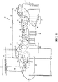
- FIG 1 schematically illustrates a gas turbine engine 20.
- the gas turbine engine 20 is disclosed herein as a two-spool turbo fan that generally incorporates a fan section 22, a compressor section 24, a combustor section 26 and a turbine section 28.
- Alternative engine architectures 200 might include an augmentor section 12, an exhaust duct section 14 and a nozzle section 16 ( Figure 2 ) among other systems or features.
- the fan section 22 drives air along a bypass flowpath while the compressor section 24 drives air along a core flowpath for compression and communication into the combustor section 26 then expansion through the turbine section 28.
- turbofan Although depicted as a turbofan in the disclosed non-limiting embodiment, it should be understood that the concepts described herein are not limited to use with turbofans as the teachings may be applied to other types of turbine engine architectures such as turbojets, turboshafts, and three-spool (plus fan) turbofans.
- the engine 20 generally includes a low spool 30 and a high spool 32 mounted for rotation about an engine central longitudinal axis X relative to an engine static structure 36 via several bearing structures 38.
- the low spool 30 generally includes an inner shaft 40 that interconnects a fan 42, a low pressure compressor (“LPC”) 44 and a low pressure turbine (“LPT”) 46.
- the inner shaft 40 drives the fan 42 directly or through a geared architecture 48 to drive the fan 42 at a lower speed than the low spool 30.
- An exemplary reduction transmission is an epicyclic transmission, namely a planetary or star gear system.
- the high spool 32 includes an outer shaft 50 that interconnects a high pressure compressor (“HPC”) 52 and high pressure turbine (“HPT”) 54.
- a combustor 56 is arranged between the high pressure compressor 52 and the high pressure turbine 54.
- the inner shaft 40 and the outer shaft 50 are concentric and rotate about the engine central longitudinal axis X which is collinear with their longitudinal axes.
- the main engine shafts 40, 50 are supported at a plurality of points by bearing structures 38 within the static structure 36. It should be understood that various bearing structures 38 at various locations may alternatively or additionally be provided.
- a full ring shroud assembly 60 within the engine case structure 36 supports a blade outer air seal (BOAS) assembly 62 with a multiple of circumferentially distributed BOAS 64 proximate to a rotor assembly 66 (one schematically shown).
- BOAS blade outer air seal
- the full ring shroud assembly 60 and the BOAS assembly 62 are axially disposed between a forward stationary vane ring 68 and an aft stationary vane ring 70.
- Each vane ring 68, 70 includes an array of vanes 72, 74 that extend between a respective inner vane platform 76, 78 and an outer vane platform 80, 82.
- the outer vane platforms 80, 82 are attached to the engine case structure 36.
- the rotor assembly 66 includes an array of blades 84 circumferentially disposed around a disk 86.
- Each blade 84 includes a root 88, a platform 90 and an airfoil 92 (also shown in Figure 4 ).
- the blade roots 88 are received within a rim 94 of the disk 86 and the airfoils 92 extend radially outward such that a tip 96 of each airfoil 92 is closest to a surface 98 of the multiple of BOAS 64 in the blade outer air seal (BOAS) assembly 62.
- the platform 90 separates a gas path side inclusive of the airfoil 92 and a non-gas path side inclusive of the root 88.
- each BOAS 64 may be formed by casting and is typically manufactured of a nickel-base alloy, and more preferably are a nickel-base superalloy.
- a nickel-base alloy has more nickel than any other element, and a nickel-base superalloy is a nickel-base alloy that is strengthened by the precipitation of gamma prime or a related phase.
- a component 100 such as the BOAS 64, and thence a substrate 102 thereof, are thus of nickel-base alloy, and more preferably are a nickel-base superalloy.
- BOAS 64 will be described and illustrated in detail as the substrate 102 of the example article, other hot section articles and components including, but not limited to, to combustor section 26 and/or turbine section 28 hardware such as augmentor components, combustor liners, blades, vanes, and other components will also benefit from the teachings herein.
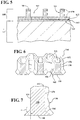
- the substrate 102 may be protected by a thermal barrier system 110 that generally includes a protective coating 112 and a ceramic feature layer 114.
- the thermal barrier system 110 as described herein, is suitable for protection of the substrate 102 manufactured of a superalloy, but while being described with reference to such superalloy gas turbine engine components, the teachings herein are generally applicable to any component on which a Thermal Barrier Coating (TBC) may be used to protect the component from a high temperature environment.
- TBC Thermal Barrier Coating
- the protective coating 112 initially includes application of a bond layer 120 on the substrate 102.
- the bond layer 120 may include an aluminum-rich composition, such as an overlay coating or a diffusion coating such as a diffusion aluminide or a diffusion platinum aluminide according to formulas such as MCrAlY, MCrAlY +Hf, and MCrAlY + HF+Si, in which M denotes nickel, cobalt, iron, platinum or mixtures thereof; Cr denotes chromium; Al denotes aluminum; and Y denotes yttrium.
- M denotes nickel, cobalt, iron, platinum or mixtures thereof
- Cr denotes chromium
- Al denotes aluminum
- Y denotes yttrium.
- MCrAlY materials are often referred to as overlay coatings because they are applied in a predetermined composition and do not interact significantly with the substrate 102 during the deposition process.
- One example preferred MCrAlY bond layer composition has a weight percent compositional range of 5-40 Cr, 8-35 Al, 0.1-2.0 Y, 0.1-7 Si, 0.1-2.0 Hf, balance selected from the group consisting of Ni, Co and mixtures thereof.
- the bond layer material may include Al, PtAl and the like, that are often referred to as diffusion coatings.
- the bond layer material may also include Al, PtAl, MCrAlY as described above, and the like, that are often referred to as cathodic arc coatings.
- the bond layer 120 may be applied by any method operable to produce a dense, uniform, adherent coating of the desired composition, such as, but not limited to, an overlay bond coat, diffusion bond coat, cathodic arc bond coat, etc.
- Such techniques may include, but are not limited to, diffusion processes (e.g., inward, outward, etc.), low pressure plasma-spray, air plasma-spray, sputtering, cathodic arc, electron beam physical vapor deposition, high velocity plasma spray techniques (e.g., HVOF, HVAF), combustion processes, wire spray techniques, laser beam cladding, electron beam cladding, etc.
- the bond layer 120 may be applied to any suitable thickness, and may be about 0.005" (5 mils; 0.127 mm) to about 0.01" (10 mils; 0.254 mm) thick. In some more specific examples, the thickness may be about 0.006" (6 mils; 0.152 mm) to about 0.007" (7 mils; 0.178 mm) thick. In one example, CATARC bond/oxidation coating thicknesses are generally less than about 0.001" (1 mil; 0.025 mm).
- the ceramic layer 122 may include a ceramic based compound that include, but are not limited to, a stabilized zirconate, a stabilized hafnate, combinations including at least one of the following compounds, and the like, for example, gadolinia stabilized zirconia, yttria stabilized zirconia, calcia stabilized zirconia, magnesia stabilized zirconia, yttria stabilized hafnia, calcia stabilized hafnia and magnesia stabilized hafnia.
- Yttria stabilized zirconia is commercially available as 7YSZ.
- One example ceramic layer 122 is about 0.05-5 mil (0.00127 - 0.127 mm) in thickness deposited, nominally at 1-3 mil (0.0254- 0.0762 mm).
- the ceramic layer 122 may be applied by various application methods to include, but are not limited to, physical vapor deposition (e.g., electron beam), thermal spray (e.g., air plasma, high velocity oxygen fuel), sputtering, sol gel, slurry, combinations comprising at least one of the foregoing application processes, and the like.
- physical vapor deposition e.g., electron beam
- thermal spray e.g., air plasma, high velocity oxygen fuel
- sputtering e.g., sol gel, slurry, combinations comprising at least one of the foregoing application processes, and the like.
- the protective coating 112 may thus include the bond layer 120 and the ceramic layer 122.
- the bond layer 120 has a temperature capability less than that of the ceramic layer 108, optionally, when there is no ceramic layer present, the protective coating 112 is often termed an "environmental coating.”
- the protective coating 112 is often termed a "bond coat.”
- the ceramic feature layer 114 overlays the protective coating 112 and is bonded thereto via an adhesive spray coat 130.
- the ceramic feature layer 114 may be formed separate from the substrate and applied as a pre-formed ceramic layer via mechanical interlocking provided by the adhesive spray coat 130.
- the ceramic feature layer 114 may include, for example, a ceramic based compound to include, but not be limited to, yttria- stabilized zirconia (YSZ), gadolinia-stabilized zirconia (GSZ), or other ceramic material that is preformed to provide a particular lattice structure 140.
- the lattice structure 140 may be of a honeycomb, circular, rectangular, triangular or other pattern with a multiple of openings 142 ( Figure 6 ).
- the ceramic feature layer 114 includes a multiple of interconnected walls 150 that form the lattice structure 140.
- Each of the multiple of interconnected walls 150 include a top surface 152, side surfaces 154, 156, and bottom surface 158.
- the bottom surface 158 may be enlarged with respect to the top surface 152 along the side surfaces 154, 156.
- the side surfaces 154, 156 include an extended area 160 such that the bottom surface 158 is enlarged with respect to the top surface 152.
- the extended area 160 is flared at an angle ⁇ of, for example, about 5 - 15 degrees ( Figure 7 ).
- the ceramic feature layer 114 may be formed separate from the substrate 102 and applied as a pre-formed ceramic layer via mechanical interlocking provided by the extended area 160 and the adhesive spray coat 130 applied thereover.
- the ceramic feature layer 114 may be machined from a solid piece, powder pressed and sintered in a near net shape, or via an additive manufacturing process that includes, but are not limited to, Sterolithography (SLA), Direct Selective Laser Sintering (DSLS), Electron Beam Sintering (EBS), Electron Beam Melting (EBM), Laser Engineered Net Shaping (LENS), Laser Net Shape Manufacturing (LNSM), Direct Metal Deposition (DMD) and Laser Powder Bed Fusion (LPBF).
- SLA Sterolithography
- DSLS Direct Selective Laser Sintering
- EBS Electron Beam Sintering
- EBM Electron Beam Melting
- LENS Laser Engineered Net Shaping
- LNSM Laser Net Shape Manufacturing
- DMD Direct Metal Deposition
- LPBF Laser Powder Bed Fusion
- the adhesive spray coat 130 may be a thermally sprayed ceramic material such as that similar to the ceramic layer 122 and is typically from about 0.003 to 0.030 inch thick (0.0762 to 0.762 mm). Thermal spraying techniques are coating processes in which melted (or heated) materials are sprayed onto a surface.
- the "feedstock" (coating precursor) is heated by electrical (plasma or arc) or chemical means (combustion flame).
- Example thermally sprayed ceramic material include, but are not limited to, Alumina (Aluminum Oxide, Al2O3, Zirconia (Zirconium Oxide, ZrO2, Chromium Oxide (Cr2O3, Titania (TiO2), Yttria stabilized Zirconia (YSZ thermal barrier coatings, ZrO2-Y2O3), and gadolinia-stabilized zirconia (GSZ).
- the adhesive spray coat 130 may completely, partially fill, or over fill the openings 142 of the ceramic feature layer 114 to form a filled "divot" and thus complete the thermal barrier system 110. In one example, the adhesive spray coat 130 may overfill the openings 142 to about twice or more the thickness of the ceramic feature layer 114.
- the adhesive spray coat 130 replaces the ceramic layer 122 such that the ceramic feature layer 114 is located directly upon the bond layer 120.
- the adhesive spray coat 130 may be bond coat composition or ceramic composition.
- a manufacture method 200 is schematically disclosed.
- the steps of the method 200 are schematically disclosed in terms of functional block diagrams as a flowchart that initially includes application of the protective coating 112 applied directly to the substrate 102 (step 202).
- the previously manufactured ceramic feature layer 114 is temporarily attached to the protective coating 112 (step 204).
- the temporary attachment may be achieved via, for example, a mechanical attachment such as a clamp, or a tack adhesive to hold the ceramic feature layer 114 in position for application of the adhesive spray coat 130 (step 206).
- the thermally sprayed adhesive spray coat 130 may completely, or partially, fill the lattice structure of the ceramic feature layer 114 to attach the ceramic feature layer 114 in an essentially unitary manner with the protective coating 112 and the substrate 102 to complete the thermal barrier system 110 therefor. It should be appreciated that alternative of addition steps may be provided without departing from the teaching herein.
- the thermal barrier system 110 beneficially supersedes GSAC in both temperature capability and manufacturability. From the temperature capability perspective, the thermal barrier system 110 eliminates the metallic layer at mid coating thickness for GSAC by replacing metallic features with the ceramic feature layer 114. This allows the 2000F (1093 C) interface limit to move deeper into the coating system to the substrate interface and allows the height of the "substrate features" to essentially be part of the ceramic coating layer. This provides better substrate protection for a given rub depth and surface temperature combination. From the manufacturing point of view, conventional metallic GSAC is relatively sensitive to the divot geometry and the spray process to obtain the desired crack propagation through the ceramic layer. The ceramic feature layer 114 inherently forms a discontinuity and does not require propagation through additional coating thickness which permits a greater effective tolerance for the divot formation.
Landscapes
- Engineering & Computer Science (AREA)
- Mechanical Engineering (AREA)
- General Engineering & Computer Science (AREA)
- Chemical & Material Sciences (AREA)
- Ceramic Engineering (AREA)
- Materials Engineering (AREA)
- Physics & Mathematics (AREA)
- Plasma & Fusion (AREA)
- Chemical Kinetics & Catalysis (AREA)
- Metallurgy (AREA)
- Organic Chemistry (AREA)
- Turbine Rotor Nozzle Sealing (AREA)
- Coating By Spraying Or Casting (AREA)
Claims (10)
- Wärmedämmsystem (110), das Folgendes umfasst:eine Schutzbeschichtung (112) auf einem Substrat (102); undeine keramische Elementschicht (114), wobei die keramische Elementschicht (114) eine Gitterstruktur (140) bildet;
dadurch gekennzeichnet, dass:
die keramische Elementschicht (114) mittels einer Sprühkleberbeschichtung (130) an der Schutzbeschichtung (112) befestigt ist, wobei die keramische Elementschicht (114) mechanisch mittels der Sprühkleberbeschichtung (130) an die Schutzbeschichtung (112) gekoppelt ist, wobei die Sprühkleberbeschichtung (130) die keramische Elementschicht (114) zumindest teilweise überläuft, wobei die keramische Elementschicht (114) einen erweiterten Bereich (160) beinhaltet, sodass die untere Fläche (158) einer Wand (150) der keramischen Elementschicht (114) in Bezug auf eine obere Fläche (152) davon erweitert ist, was die mechanische Kupplung zwischen der keramischen Elementschicht (114) und der Schutzbeschichtung (112) mittels der Sprühkleberbeschichtung (130) ermöglicht und wobei der erweitere Bereich (160) aufgeweitet ist. - Wärmedämmsystem nach Anspruch 1, wobei das Substrat (102) ein metallisches Substrat ist, und wobei die Schutzbeschichtung (112) ein keramisches Material beinhaltet.
- Wärmedämmsystem nach Anspruch 1 oder 2, wobei die Schutzbeschichtung (112) eine umweltbeständige Beschichtung ist.
- Wärmedämmsystem nach Anspruch 1 oder 2, wobei die Schutzbeschichtung eine Haftbeschichtung (120) ist.
- Wärmedämmsystem nach einem der vorhergehenden Ansprüche, wobei der erweiterte Bereich (160) in einem Winkel (α) von 5 bis 15 Grad in Bezug auf eine Seitenwand der keramischen Elementschicht (114) aufgeweitet ist.
- Wärmedämmsystem nach einem der vorhergehenden Ansprüche, wobei die Sprühkleberbeschichtung (130) zwischen 0,003 und 0,030 Inch (0,0762 und 0,762 mm) dick ist.
- Wärmedämmsystem nach einem der vorhergehenden Ansprüche, wobei die keramische Elementschicht (114) ein Wabenmuster bildet.
- Verfahren zum Anbringen des Wärmedämmsystems (110) an ein Bauelement (102), das Folgendes umfasst:Anbringen einer Schutzbeschichtung (112) auf ein Substrat (102) ;dadurch gekennzeichnet, dass:
das Verfahren ferner das mechanische Koppeln einer keramischen Elementschicht (114) mit der Schutzbeschichtung (112) mittels einer Sprühkleberbeschichtung (130) umfasst, die thermisch auf die keramische Elementschicht (114) und die Schutzbeschichtung (112) aufgespritzt ist und wobei zumindest ein Teil der keramischen Elementschicht (114) mit der Sprühkleberbeschichtung (130) gefüllt ist, wobei die keramische Elementschicht (114) vor dem thermischen Aufspritzen der Sprühkleberbeschichtung (130) mechanisch an die Schutzbeschichtung (112) angebracht ist, wobei die keramische Elementschicht (114) vor dem thermischen Aufspritzen der Sprühkleberbeschichtung (130) vorübergehend an die Schutzbeschichtung (112) geheftet ist, wobei die keramische Elementschicht (114) einen erweiterten Bereich (160) einschließt, sodass eine untere Fläche (158) einer Wand (150) der keramischen Elementschicht (114) in Bezug auf eine obere Fläche (152) davon erweitert ist, was die mechanische Kupplung zwischen der keramischen Elementschicht (114) und der Schutzbeschichtung (112) mittels der Sprühkleberbeschichtung (130) erleichtert und wobei der erweitere Bereich (160) aufgeweitet ist. - Verfahren nach Anspruch 8, ferner umfassend das Vorformen der keramischen Elementschicht (114).
- Verfahren nach Anspruch 8 oder 9, ferner umfassend die zusätzliche Herstellung der keramischen Elementschicht (114).
Applications Claiming Priority (1)
| Application Number | Priority Date | Filing Date | Title |
|---|---|---|---|
| US201462072478P | 2014-10-30 | 2014-10-30 |
Publications (2)
| Publication Number | Publication Date |
|---|---|
| EP3029274A1 EP3029274A1 (de) | 2016-06-08 |
| EP3029274B1 true EP3029274B1 (de) | 2020-03-11 |
Family
ID=54360091
Family Applications (1)
| Application Number | Title | Priority Date | Filing Date |
|---|---|---|---|
| EP15191109.6A Active EP3029274B1 (de) | 2014-10-30 | 2015-10-22 | Thermisch gespritztes bonding einer keramikstruktur auf ein substrat |
Country Status (4)
| Country | Link |
|---|---|
| US (2) | US10458256B2 (de) |
| EP (1) | EP3029274B1 (de) |
| JP (1) | JP6158895B2 (de) |
| SG (1) | SG10201508755PA (de) |
Families Citing this family (21)
| Publication number | Priority date | Publication date | Assignee | Title |
|---|---|---|---|---|
| DE102011108957B4 (de) * | 2011-07-29 | 2013-07-04 | Mtu Aero Engines Gmbh | Verfahren zum Herstellen, Reparieren und/oder Austauschen eines Gehäuses, insbesondere eines Triebwerkgehäuses, sowie ein entsprechendes Gehäuse |
| US10443444B2 (en) | 2014-05-21 | 2019-10-15 | United Technologies Corporation | Cost effective manufacturing method for GSAC incorporating a stamped preform |
| US20170159442A1 (en) * | 2015-12-02 | 2017-06-08 | United Technologies Corporation | Coated and uncoated surface-modified airfoils for a gas turbine engine component and methods for controlling the direction of incident energy reflection from an airfoil |
| US10774670B2 (en) * | 2017-06-07 | 2020-09-15 | General Electric Company | Filled abradable seal component and associated methods thereof |
| DE102017211316A1 (de) * | 2017-07-04 | 2019-01-10 | MTU Aero Engines AG | Turbomaschinen-Dichtring |
| US11059559B2 (en) | 2018-03-05 | 2021-07-13 | General Electric Company | Acoustic liners with oblique cellular structures |
| US11047304B2 (en) | 2018-08-08 | 2021-06-29 | General Electric Company | Acoustic cores with sound-attenuating protuberances |
| US10823059B2 (en) | 2018-10-03 | 2020-11-03 | General Electric Company | Acoustic core assemblies with mechanically joined acoustic core segments, and methods of mechanically joining acoustic core segments |
| US10927695B2 (en) * | 2018-11-27 | 2021-02-23 | Raytheon Technologies Corporation | Abradable coating for grooved BOAS |
| US11187100B2 (en) | 2018-12-03 | 2021-11-30 | Raytheon Technologies Corporation | CMC honeycomb base for abradable coating on CMC BOAS |
| US11434819B2 (en) | 2019-03-29 | 2022-09-06 | General Electric Company | Acoustic liners with enhanced acoustic absorption and reduced drag characteristics |
| CN110205626B (zh) * | 2019-07-03 | 2024-01-23 | 西安热工研究院有限公司 | 一种功能梯度热障涂层及其制备方法 |
| US11668236B2 (en) | 2020-07-24 | 2023-06-06 | General Electric Company | Acoustic liners with low-frequency sound wave attenuating features |
| CN114909223A (zh) * | 2021-02-08 | 2022-08-16 | 中国航发商用航空发动机有限责任公司 | 航空发动机声衬装置以及航空发动机 |
| US11970992B2 (en) | 2021-06-03 | 2024-04-30 | General Electric Company | Acoustic cores and tools and methods for forming the same |
| US12142253B2 (en) | 2021-10-05 | 2024-11-12 | General Electric Company | Solid adhesive film for acoustic liner and method |
| US11965425B2 (en) | 2022-05-31 | 2024-04-23 | General Electric Company | Airfoil for a turbofan engine |
| EP4317114A1 (de) * | 2022-08-05 | 2024-02-07 | RTX Corporation | Keramikmatrixverbundartikel und verfahren zur herstellung davon |
| US12312969B2 (en) | 2023-01-17 | 2025-05-27 | General Electric Company | Airfoils for turbofan engines |
| WO2024233690A2 (en) * | 2023-05-09 | 2024-11-14 | Supernal, Llc | Systems and methods for thermal spraying of protective materials onto composite laminates |
| CN118082319B (zh) * | 2024-02-01 | 2025-12-16 | 福耀玻璃工业集团股份有限公司 | 挡风玻璃及其制备方法和车辆 |
Family Cites Families (25)
| Publication number | Priority date | Publication date | Assignee | Title |
|---|---|---|---|---|
| BE793005A (fr) | 1971-12-20 | 1973-06-19 | Union Carbide Corp | Elements metalliques poreux renforces par une feuille |
| DE8013163U1 (de) * | 1980-05-16 | 1988-10-13 | MTU Motoren- und Turbinen-Union München GmbH, 8000 München | Gehäuse für eine thermische Turbomaschine mit einer wärmedämmenden Auskleidung |
| US4639388A (en) * | 1985-02-12 | 1987-01-27 | Chromalloy American Corporation | Ceramic-metal composites |
| JP2745326B2 (ja) * | 1989-05-29 | 1998-04-28 | 昭和飛行機工業株式会社 | 溶射被膜構造 |
| DE4238369C2 (de) | 1992-11-13 | 1996-09-26 | Mtu Muenchen Gmbh | Bauteil aus einem metallischen Grundsubstrat mit keramischer Beschichtung |
| US5419971A (en) * | 1993-03-03 | 1995-05-30 | General Electric Company | Enhanced thermal barrier coating system |
| US6235370B1 (en) | 1999-03-03 | 2001-05-22 | Siemens Westinghouse Power Corporation | High temperature erosion resistant, abradable thermal barrier composite coating |
| US20130191278A1 (en) | 1999-05-03 | 2013-07-25 | Jpmorgan Chase Bank, N.A. | Method and System for Processing Internet Payments Using the Electronic Funds Transfer Network |
| DE10117127B4 (de) | 2001-04-06 | 2009-12-31 | Alstom Technology Ltd. | Verbundaufbau zwischen metallischen und nichtmetallischen Materialien |
| DE10121019A1 (de) | 2001-04-28 | 2002-10-31 | Alstom Switzerland Ltd | Gasturbinendichtung |
| US6846574B2 (en) * | 2001-05-16 | 2005-01-25 | Siemens Westinghouse Power Corporation | Honeycomb structure thermal barrier coating |
| US6537021B2 (en) | 2001-06-06 | 2003-03-25 | Chromalloy Gas Turbine Corporation | Abradeable seal system |
| US8357454B2 (en) * | 2001-08-02 | 2013-01-22 | Siemens Energy, Inc. | Segmented thermal barrier coating |
| DE60308002D1 (de) | 2003-06-26 | 2006-10-12 | Alstom Technology Ltd | Verfahren für das Auftragen eines mehrschichtigen Systems |
| US20050153160A1 (en) * | 2004-01-12 | 2005-07-14 | Yourong Liu | Durable thermal barrier coating having low thermal conductivity |
| US20070224359A1 (en) | 2006-03-22 | 2007-09-27 | Burin David L | Method for preparing strain tolerant coatings by a sol-gel process |
| US7875370B2 (en) | 2006-08-18 | 2011-01-25 | United Technologies Corporation | Thermal barrier coating with a plasma spray top layer |
| US8061978B2 (en) | 2007-10-16 | 2011-11-22 | United Technologies Corp. | Systems and methods involving abradable air seals |
| US8079806B2 (en) | 2007-11-28 | 2011-12-20 | United Technologies Corporation | Segmented ceramic layer for member of gas turbine engine |
| US20090324401A1 (en) | 2008-05-02 | 2009-12-31 | General Electric Company | Article having a protective coating and methods |
| EP2174740A1 (de) | 2008-10-08 | 2010-04-14 | Siemens Aktiengesellschaft | Wabendichtung und Verfahren zu deren Herstellung |
| EP2233450A1 (de) * | 2009-03-27 | 2010-09-29 | Alstom Technology Ltd | Mehrlagiges thermisches Schutzsystem und deren Verwendung |
| US9194243B2 (en) | 2009-07-17 | 2015-11-24 | Rolls-Royce Corporation | Substrate features for mitigating stress |
| US8506243B2 (en) | 2009-11-19 | 2013-08-13 | United Technologies Corporation | Segmented thermally insulating coating |
| US8535783B2 (en) | 2010-06-08 | 2013-09-17 | United Technologies Corporation | Ceramic coating systems and methods |
-
2015
- 2015-10-22 EP EP15191109.6A patent/EP3029274B1/de active Active
- 2015-10-23 SG SG10201508755PA patent/SG10201508755PA/en unknown
- 2015-10-27 US US14/923,574 patent/US10458256B2/en active Active
- 2015-10-28 JP JP2015211469A patent/JP6158895B2/ja active Active
-
2019
- 2019-06-28 US US16/456,569 patent/US20190323365A1/en not_active Abandoned
Non-Patent Citations (1)
| Title |
|---|
| None * |
Also Published As
| Publication number | Publication date |
|---|---|
| US10458256B2 (en) | 2019-10-29 |
| US20160123160A1 (en) | 2016-05-05 |
| EP3029274A1 (de) | 2016-06-08 |
| JP6158895B2 (ja) | 2017-07-05 |
| SG10201508755PA (en) | 2016-05-30 |
| JP2016089831A (ja) | 2016-05-23 |
| US20190323365A1 (en) | 2019-10-24 |
Similar Documents
| Publication | Publication Date | Title |
|---|---|---|
| EP3029274B1 (de) | Thermisch gespritztes bonding einer keramikstruktur auf ein substrat | |
| US20210025592A1 (en) | Methods of repairing a thermal barrier coating of a gas turbine component and the resulting components | |
| EP2325347B1 (de) | Segmentierte, wärmeisolierende Beschichtung | |
| US20090191347A1 (en) | Turbine component other than airfoil having ceramic corrosion resistant coating and methods for making same | |
| EP2947173B1 (de) | Calcium-magnesium-aluminiumsilikat (cmas)-resistente wärmedämmschicht und beschichtungsverfahren dafür | |
| EP3640360B1 (de) | Herstellungverfahren einer geometrisch segmentierten abreibbaren keramischen wärmedämmschicht mit verbesserter spallationsbeständigkeit | |
| JP2008151128A (ja) | ガスタービンエンジン構成要素、そのコーティング方法およびコーティング設計方法 | |
| EP3184668A1 (de) | Gasturbinenkomponente mit verbessertem wärmedämmschichtsystem | |
| EP3748031B1 (de) | Reflektierende beschichtung und beschichtungsverfahren dafür | |
| EP3002348B1 (de) | Verfahren zum beschichten von gasturbinenmotorkomponenten mit mehrphasigen vorreagierten wärmedämmschichten und beschichtete gasturbinenmotorkomponenten | |
| EP2431495A1 (de) | Verfahren zum Formen einer Wärmeabgrenzungsschicht und Vorrichtung mit der Wärmeabgrenzungsschicht | |
| EP3323999B1 (de) | Endwandbogensegmente mit abdeckung über verbindungsstelle | |
| EP3196419A1 (de) | Äussere laufschaufelluftdichtung mit einer oberflächenschicht mit taschen | |
| EP3693490A1 (de) | Artikel mit keramischer sperrschicht und schicht aus vernetzten keramischen nanofasern | |
| EP2937514B1 (de) | Gasturbinenmotor-turbinenschaufelspitze mit beschichteter aussparung | |
| EP3421729B1 (de) | Aluminiumoxidabdichtungsbeschichtung mit zwischenschicht | |
| EP2423347A1 (de) | Verfahren zum Bilden einer Wärmegrenzbeschichtung und Turbinenkomponente mit der Wärmegrenzbeschichtung | |
| EP4636224A1 (de) | Geometrisch segmentierte beschichtung zur wärmedämmung und abreibbarkeitsschutz | |
| EP3556998B1 (de) | Luftdichtung mit gaswegabschnitt mit geometrisch segmentierter beschichtung |
Legal Events
| Date | Code | Title | Description |
|---|---|---|---|
| PUAI | Public reference made under article 153(3) epc to a published international application that has entered the european phase |
Free format text: ORIGINAL CODE: 0009012 |
|
| AK | Designated contracting states |
Kind code of ref document: A1 Designated state(s): AL AT BE BG CH CY CZ DE DK EE ES FI FR GB GR HR HU IE IS IT LI LT LU LV MC MK MT NL NO PL PT RO RS SE SI SK SM TR |
|
| AX | Request for extension of the european patent |
Extension state: BA ME |
|
| RAP1 | Party data changed (applicant data changed or rights of an application transferred) |
Owner name: UNITED TECHNOLOGIES CORPORATION |
|
| STAA | Information on the status of an ep patent application or granted ep patent |
Free format text: STATUS: REQUEST FOR EXAMINATION WAS MADE |
|
| 17P | Request for examination filed |
Effective date: 20161208 |
|
| RBV | Designated contracting states (corrected) |
Designated state(s): AL AT BE BG CH CY CZ DE DK EE ES FI FR GB GR HR HU IE IS IT LI LT LU LV MC MK MT NL NO PL PT RO RS SE SI SK SM TR |
|
| STAA | Information on the status of an ep patent application or granted ep patent |
Free format text: STATUS: EXAMINATION IS IN PROGRESS |
|
| 17Q | First examination report despatched |
Effective date: 20190103 |
|
| REG | Reference to a national code |
Ref country code: DE Ref legal event code: R079 Ref document number: 602015048488 Country of ref document: DE Free format text: PREVIOUS MAIN CLASS: F01D0011080000 Ipc: F01D0009040000 |
|
| RIC1 | Information provided on ipc code assigned before grant |
Ipc: F01D 11/08 20060101ALI20190730BHEP Ipc: B23B 9/04 20060101ALI20190730BHEP Ipc: F01D 5/28 20060101ALI20190730BHEP Ipc: C23C 4/12 20160101ALI20190730BHEP Ipc: B32B 9/00 20060101ALI20190730BHEP Ipc: F01D 11/12 20060101ALI20190730BHEP Ipc: F01D 9/04 20060101AFI20190730BHEP Ipc: F01D 25/08 20060101ALI20190730BHEP Ipc: B32B 9/04 20060101ALI20190730BHEP Ipc: B32B 37/12 20060101ALI20190730BHEP Ipc: B32B 3/12 20060101ALI20190730BHEP Ipc: B32B 7/12 20060101ALI20190730BHEP |
|
| GRAP | Despatch of communication of intention to grant a patent |
Free format text: ORIGINAL CODE: EPIDOSNIGR1 |
|
| STAA | Information on the status of an ep patent application or granted ep patent |
Free format text: STATUS: GRANT OF PATENT IS INTENDED |
|
| INTG | Intention to grant announced |
Effective date: 20190924 |
|
| GRAS | Grant fee paid |
Free format text: ORIGINAL CODE: EPIDOSNIGR3 |
|
| GRAA | (expected) grant |
Free format text: ORIGINAL CODE: 0009210 |
|
| STAA | Information on the status of an ep patent application or granted ep patent |
Free format text: STATUS: THE PATENT HAS BEEN GRANTED |
|
| AK | Designated contracting states |
Kind code of ref document: B1 Designated state(s): AL AT BE BG CH CY CZ DE DK EE ES FI FR GB GR HR HU IE IS IT LI LT LU LV MC MK MT NL NO PL PT RO RS SE SI SK SM TR |
|
| REG | Reference to a national code |
Ref country code: GB Ref legal event code: FG4D |
|
| REG | Reference to a national code |
Ref country code: CH Ref legal event code: EP |
|
| REG | Reference to a national code |
Ref country code: AT Ref legal event code: REF Ref document number: 1243377 Country of ref document: AT Kind code of ref document: T Effective date: 20200315 |
|
| REG | Reference to a national code |
Ref country code: IE Ref legal event code: FG4D |
|
| REG | Reference to a national code |
Ref country code: DE Ref legal event code: R096 Ref document number: 602015048488 Country of ref document: DE |
|
| PG25 | Lapsed in a contracting state [announced via postgrant information from national office to epo] |
Ref country code: FI Free format text: LAPSE BECAUSE OF FAILURE TO SUBMIT A TRANSLATION OF THE DESCRIPTION OR TO PAY THE FEE WITHIN THE PRESCRIBED TIME-LIMIT Effective date: 20200311 Ref country code: NO Free format text: LAPSE BECAUSE OF FAILURE TO SUBMIT A TRANSLATION OF THE DESCRIPTION OR TO PAY THE FEE WITHIN THE PRESCRIBED TIME-LIMIT Effective date: 20200611 Ref country code: RS Free format text: LAPSE BECAUSE OF FAILURE TO SUBMIT A TRANSLATION OF THE DESCRIPTION OR TO PAY THE FEE WITHIN THE PRESCRIBED TIME-LIMIT Effective date: 20200311 |
|
| REG | Reference to a national code |
Ref country code: NL Ref legal event code: MP Effective date: 20200311 |
|
| PG25 | Lapsed in a contracting state [announced via postgrant information from national office to epo] |
Ref country code: LV Free format text: LAPSE BECAUSE OF FAILURE TO SUBMIT A TRANSLATION OF THE DESCRIPTION OR TO PAY THE FEE WITHIN THE PRESCRIBED TIME-LIMIT Effective date: 20200311 Ref country code: SE Free format text: LAPSE BECAUSE OF FAILURE TO SUBMIT A TRANSLATION OF THE DESCRIPTION OR TO PAY THE FEE WITHIN THE PRESCRIBED TIME-LIMIT Effective date: 20200311 Ref country code: HR Free format text: LAPSE BECAUSE OF FAILURE TO SUBMIT A TRANSLATION OF THE DESCRIPTION OR TO PAY THE FEE WITHIN THE PRESCRIBED TIME-LIMIT Effective date: 20200311 Ref country code: GR Free format text: LAPSE BECAUSE OF FAILURE TO SUBMIT A TRANSLATION OF THE DESCRIPTION OR TO PAY THE FEE WITHIN THE PRESCRIBED TIME-LIMIT Effective date: 20200612 Ref country code: BG Free format text: LAPSE BECAUSE OF FAILURE TO SUBMIT A TRANSLATION OF THE DESCRIPTION OR TO PAY THE FEE WITHIN THE PRESCRIBED TIME-LIMIT Effective date: 20200611 |
|
| REG | Reference to a national code |
Ref country code: LT Ref legal event code: MG4D |
|
| PG25 | Lapsed in a contracting state [announced via postgrant information from national office to epo] |
Ref country code: NL Free format text: LAPSE BECAUSE OF FAILURE TO SUBMIT A TRANSLATION OF THE DESCRIPTION OR TO PAY THE FEE WITHIN THE PRESCRIBED TIME-LIMIT Effective date: 20200311 |
|
| PG25 | Lapsed in a contracting state [announced via postgrant information from national office to epo] |
Ref country code: SM Free format text: LAPSE BECAUSE OF FAILURE TO SUBMIT A TRANSLATION OF THE DESCRIPTION OR TO PAY THE FEE WITHIN THE PRESCRIBED TIME-LIMIT Effective date: 20200311 Ref country code: EE Free format text: LAPSE BECAUSE OF FAILURE TO SUBMIT A TRANSLATION OF THE DESCRIPTION OR TO PAY THE FEE WITHIN THE PRESCRIBED TIME-LIMIT Effective date: 20200311 Ref country code: LT Free format text: LAPSE BECAUSE OF FAILURE TO SUBMIT A TRANSLATION OF THE DESCRIPTION OR TO PAY THE FEE WITHIN THE PRESCRIBED TIME-LIMIT Effective date: 20200311 Ref country code: CZ Free format text: LAPSE BECAUSE OF FAILURE TO SUBMIT A TRANSLATION OF THE DESCRIPTION OR TO PAY THE FEE WITHIN THE PRESCRIBED TIME-LIMIT Effective date: 20200311 Ref country code: RO Free format text: LAPSE BECAUSE OF FAILURE TO SUBMIT A TRANSLATION OF THE DESCRIPTION OR TO PAY THE FEE WITHIN THE PRESCRIBED TIME-LIMIT Effective date: 20200311 Ref country code: PT Free format text: LAPSE BECAUSE OF FAILURE TO SUBMIT A TRANSLATION OF THE DESCRIPTION OR TO PAY THE FEE WITHIN THE PRESCRIBED TIME-LIMIT Effective date: 20200805 Ref country code: SK Free format text: LAPSE BECAUSE OF FAILURE TO SUBMIT A TRANSLATION OF THE DESCRIPTION OR TO PAY THE FEE WITHIN THE PRESCRIBED TIME-LIMIT Effective date: 20200311 Ref country code: IS Free format text: LAPSE BECAUSE OF FAILURE TO SUBMIT A TRANSLATION OF THE DESCRIPTION OR TO PAY THE FEE WITHIN THE PRESCRIBED TIME-LIMIT Effective date: 20200711 |
|
| REG | Reference to a national code |
Ref country code: AT Ref legal event code: MK05 Ref document number: 1243377 Country of ref document: AT Kind code of ref document: T Effective date: 20200311 |
|
| REG | Reference to a national code |
Ref country code: DE Ref legal event code: R097 Ref document number: 602015048488 Country of ref document: DE |
|
| PLBE | No opposition filed within time limit |
Free format text: ORIGINAL CODE: 0009261 |
|
| STAA | Information on the status of an ep patent application or granted ep patent |
Free format text: STATUS: NO OPPOSITION FILED WITHIN TIME LIMIT |
|
| PG25 | Lapsed in a contracting state [announced via postgrant information from national office to epo] |
Ref country code: ES Free format text: LAPSE BECAUSE OF FAILURE TO SUBMIT A TRANSLATION OF THE DESCRIPTION OR TO PAY THE FEE WITHIN THE PRESCRIBED TIME-LIMIT Effective date: 20200311 Ref country code: AT Free format text: LAPSE BECAUSE OF FAILURE TO SUBMIT A TRANSLATION OF THE DESCRIPTION OR TO PAY THE FEE WITHIN THE PRESCRIBED TIME-LIMIT Effective date: 20200311 Ref country code: IT Free format text: LAPSE BECAUSE OF FAILURE TO SUBMIT A TRANSLATION OF THE DESCRIPTION OR TO PAY THE FEE WITHIN THE PRESCRIBED TIME-LIMIT Effective date: 20200311 Ref country code: DK Free format text: LAPSE BECAUSE OF FAILURE TO SUBMIT A TRANSLATION OF THE DESCRIPTION OR TO PAY THE FEE WITHIN THE PRESCRIBED TIME-LIMIT Effective date: 20200311 |
|
| 26N | No opposition filed |
Effective date: 20201214 |
|
| PG25 | Lapsed in a contracting state [announced via postgrant information from national office to epo] |
Ref country code: SI Free format text: LAPSE BECAUSE OF FAILURE TO SUBMIT A TRANSLATION OF THE DESCRIPTION OR TO PAY THE FEE WITHIN THE PRESCRIBED TIME-LIMIT Effective date: 20200311 Ref country code: PL Free format text: LAPSE BECAUSE OF FAILURE TO SUBMIT A TRANSLATION OF THE DESCRIPTION OR TO PAY THE FEE WITHIN THE PRESCRIBED TIME-LIMIT Effective date: 20200311 |
|
| REG | Reference to a national code |
Ref country code: CH Ref legal event code: PL |
|
| PG25 | Lapsed in a contracting state [announced via postgrant information from national office to epo] |
Ref country code: LU Free format text: LAPSE BECAUSE OF NON-PAYMENT OF DUE FEES Effective date: 20201022 Ref country code: MC Free format text: LAPSE BECAUSE OF FAILURE TO SUBMIT A TRANSLATION OF THE DESCRIPTION OR TO PAY THE FEE WITHIN THE PRESCRIBED TIME-LIMIT Effective date: 20200311 |
|
| REG | Reference to a national code |
Ref country code: BE Ref legal event code: MM Effective date: 20201031 |
|
| PG25 | Lapsed in a contracting state [announced via postgrant information from national office to epo] |
Ref country code: LI Free format text: LAPSE BECAUSE OF NON-PAYMENT OF DUE FEES Effective date: 20201031 Ref country code: BE Free format text: LAPSE BECAUSE OF NON-PAYMENT OF DUE FEES Effective date: 20201031 Ref country code: CH Free format text: LAPSE BECAUSE OF NON-PAYMENT OF DUE FEES Effective date: 20201031 |
|
| PG25 | Lapsed in a contracting state [announced via postgrant information from national office to epo] |
Ref country code: IE Free format text: LAPSE BECAUSE OF NON-PAYMENT OF DUE FEES Effective date: 20201022 |
|
| PG25 | Lapsed in a contracting state [announced via postgrant information from national office to epo] |
Ref country code: TR Free format text: LAPSE BECAUSE OF FAILURE TO SUBMIT A TRANSLATION OF THE DESCRIPTION OR TO PAY THE FEE WITHIN THE PRESCRIBED TIME-LIMIT Effective date: 20200311 Ref country code: MT Free format text: LAPSE BECAUSE OF FAILURE TO SUBMIT A TRANSLATION OF THE DESCRIPTION OR TO PAY THE FEE WITHIN THE PRESCRIBED TIME-LIMIT Effective date: 20200311 Ref country code: CY Free format text: LAPSE BECAUSE OF FAILURE TO SUBMIT A TRANSLATION OF THE DESCRIPTION OR TO PAY THE FEE WITHIN THE PRESCRIBED TIME-LIMIT Effective date: 20200311 |
|
| PG25 | Lapsed in a contracting state [announced via postgrant information from national office to epo] |
Ref country code: MK Free format text: LAPSE BECAUSE OF FAILURE TO SUBMIT A TRANSLATION OF THE DESCRIPTION OR TO PAY THE FEE WITHIN THE PRESCRIBED TIME-LIMIT Effective date: 20200311 Ref country code: AL Free format text: LAPSE BECAUSE OF FAILURE TO SUBMIT A TRANSLATION OF THE DESCRIPTION OR TO PAY THE FEE WITHIN THE PRESCRIBED TIME-LIMIT Effective date: 20200311 |
|
| REG | Reference to a national code |
Ref country code: DE Ref legal event code: R081 Ref document number: 602015048488 Country of ref document: DE Owner name: RAYTHEON TECHNOLOGIES CORPORATION (N.D.GES.D.S, US Free format text: FORMER OWNER: UNITED TECHNOLOGIES CORPORATION, FARMINGTON, CONN., US Ref country code: DE Ref legal event code: R081 Ref document number: 602015048488 Country of ref document: DE Owner name: RTX CORPORATION (N.D.GES.D. STAATES DELAWARE),, US Free format text: FORMER OWNER: UNITED TECHNOLOGIES CORPORATION, FARMINGTON, CONN., US |
|
| P01 | Opt-out of the competence of the unified patent court (upc) registered |
Effective date: 20230520 |
|
| PGFP | Annual fee paid to national office [announced via postgrant information from national office to epo] |
Ref country code: GB Payment date: 20250923 Year of fee payment: 11 |
|
| PGFP | Annual fee paid to national office [announced via postgrant information from national office to epo] |
Ref country code: FR Payment date: 20250924 Year of fee payment: 11 |
|
| REG | Reference to a national code |
Ref country code: DE Ref legal event code: R081 Ref document number: 602015048488 Country of ref document: DE Owner name: RTX CORPORATION (N.D.GES.D. STAATES DELAWARE),, US Free format text: FORMER OWNER: RAYTHEON TECHNOLOGIES CORPORATION (N.D.GES.D.STAATES DELAWARE), ARLINGTON, VA, US |
|
| PGFP | Annual fee paid to national office [announced via postgrant information from national office to epo] |
Ref country code: DE Payment date: 20250923 Year of fee payment: 11 |