EP3029399A1 - Kühlschrank - Google Patents
Kühlschrank Download PDFInfo
- Publication number
- EP3029399A1 EP3029399A1 EP15197222.1A EP15197222A EP3029399A1 EP 3029399 A1 EP3029399 A1 EP 3029399A1 EP 15197222 A EP15197222 A EP 15197222A EP 3029399 A1 EP3029399 A1 EP 3029399A1
- Authority
- EP
- European Patent Office
- Prior art keywords
- cold air
- refrigerating
- flow path
- circulation fan
- evaporator
- Prior art date
- Legal status (The legal status is an assumption and is not a legal conclusion. Google has not performed a legal analysis and makes no representation as to the accuracy of the status listed.)
- Withdrawn
Links
Images







Classifications
-
- F—MECHANICAL ENGINEERING; LIGHTING; HEATING; WEAPONS; BLASTING
- F25—REFRIGERATION OR COOLING; COMBINED HEATING AND REFRIGERATION SYSTEMS; HEAT PUMP SYSTEMS; MANUFACTURE OR STORAGE OF ICE; LIQUEFACTION SOLIDIFICATION OF GASES
- F25D—REFRIGERATORS; COLD ROOMS; ICE-BOXES; COOLING OR FREEZING APPARATUS NOT OTHERWISE PROVIDED FOR
- F25D17/00—Arrangements for circulating cooling fluids; Arrangements for circulating gas, e.g. air, within refrigerated spaces
- F25D17/04—Arrangements for circulating cooling fluids; Arrangements for circulating gas, e.g. air, within refrigerated spaces for circulating air, e.g. by convection
- F25D17/06—Arrangements for circulating cooling fluids; Arrangements for circulating gas, e.g. air, within refrigerated spaces for circulating air, e.g. by convection by forced circulation
- F25D17/062—Arrangements for circulating cooling fluids; Arrangements for circulating gas, e.g. air, within refrigerated spaces for circulating air, e.g. by convection by forced circulation in household refrigerators
- F25D17/065—Arrangements for circulating cooling fluids; Arrangements for circulating gas, e.g. air, within refrigerated spaces for circulating air, e.g. by convection by forced circulation in household refrigerators with compartments at different temperatures
-
- F—MECHANICAL ENGINEERING; LIGHTING; HEATING; WEAPONS; BLASTING
- F25—REFRIGERATION OR COOLING; COMBINED HEATING AND REFRIGERATION SYSTEMS; HEAT PUMP SYSTEMS; MANUFACTURE OR STORAGE OF ICE; LIQUEFACTION SOLIDIFICATION OF GASES
- F25D—REFRIGERATORS; COLD ROOMS; ICE-BOXES; COOLING OR FREEZING APPARATUS NOT OTHERWISE PROVIDED FOR
- F25D11/00—Self-contained movable devices, e.g. domestic refrigerators
- F25D11/02—Self-contained movable devices, e.g. domestic refrigerators with cooling compartments at different temperatures
- F25D11/022—Self-contained movable devices, e.g. domestic refrigerators with cooling compartments at different temperatures with two or more evaporators
-
- F—MECHANICAL ENGINEERING; LIGHTING; HEATING; WEAPONS; BLASTING
- F25—REFRIGERATION OR COOLING; COMBINED HEATING AND REFRIGERATION SYSTEMS; HEAT PUMP SYSTEMS; MANUFACTURE OR STORAGE OF ICE; LIQUEFACTION SOLIDIFICATION OF GASES
- F25D—REFRIGERATORS; COLD ROOMS; ICE-BOXES; COOLING OR FREEZING APPARATUS NOT OTHERWISE PROVIDED FOR
- F25D17/00—Arrangements for circulating cooling fluids; Arrangements for circulating gas, e.g. air, within refrigerated spaces
- F25D17/04—Arrangements for circulating cooling fluids; Arrangements for circulating gas, e.g. air, within refrigerated spaces for circulating air, e.g. by convection
-
- F—MECHANICAL ENGINEERING; LIGHTING; HEATING; WEAPONS; BLASTING
- F25—REFRIGERATION OR COOLING; COMBINED HEATING AND REFRIGERATION SYSTEMS; HEAT PUMP SYSTEMS; MANUFACTURE OR STORAGE OF ICE; LIQUEFACTION SOLIDIFICATION OF GASES
- F25D—REFRIGERATORS; COLD ROOMS; ICE-BOXES; COOLING OR FREEZING APPARATUS NOT OTHERWISE PROVIDED FOR
- F25D29/00—Arrangement or mounting of control or safety devices
-
- F—MECHANICAL ENGINEERING; LIGHTING; HEATING; WEAPONS; BLASTING
- F25—REFRIGERATION OR COOLING; COMBINED HEATING AND REFRIGERATION SYSTEMS; HEAT PUMP SYSTEMS; MANUFACTURE OR STORAGE OF ICE; LIQUEFACTION SOLIDIFICATION OF GASES
- F25B—REFRIGERATION MACHINES, PLANTS OR SYSTEMS; COMBINED HEATING AND REFRIGERATION SYSTEMS; HEAT PUMP SYSTEMS
- F25B2600/00—Control issues
- F25B2600/11—Fan speed control
- F25B2600/112—Fan speed control of evaporator fans
-
- F—MECHANICAL ENGINEERING; LIGHTING; HEATING; WEAPONS; BLASTING
- F25—REFRIGERATION OR COOLING; COMBINED HEATING AND REFRIGERATION SYSTEMS; HEAT PUMP SYSTEMS; MANUFACTURE OR STORAGE OF ICE; LIQUEFACTION SOLIDIFICATION OF GASES
- F25B—REFRIGERATION MACHINES, PLANTS OR SYSTEMS; COMBINED HEATING AND REFRIGERATION SYSTEMS; HEAT PUMP SYSTEMS
- F25B2600/00—Control issues
- F25B2600/25—Control of valves
- F25B2600/2511—Evaporator distribution valves
-
- F—MECHANICAL ENGINEERING; LIGHTING; HEATING; WEAPONS; BLASTING
- F25—REFRIGERATION OR COOLING; COMBINED HEATING AND REFRIGERATION SYSTEMS; HEAT PUMP SYSTEMS; MANUFACTURE OR STORAGE OF ICE; LIQUEFACTION SOLIDIFICATION OF GASES
- F25D—REFRIGERATORS; COLD ROOMS; ICE-BOXES; COOLING OR FREEZING APPARATUS NOT OTHERWISE PROVIDED FOR
- F25D2317/00—Details or arrangements for circulating cooling fluids; Details or arrangements for circulating gas, e.g. air, within refrigerated spaces, not provided for in other groups of this subclass
- F25D2317/06—Details or arrangements for circulating cooling fluids; Details or arrangements for circulating gas, e.g. air, within refrigerated spaces, not provided for in other groups of this subclass with forced air circulation
- F25D2317/061—Details or arrangements for circulating cooling fluids; Details or arrangements for circulating gas, e.g. air, within refrigerated spaces, not provided for in other groups of this subclass with forced air circulation through special compartments
-
- F—MECHANICAL ENGINEERING; LIGHTING; HEATING; WEAPONS; BLASTING
- F25—REFRIGERATION OR COOLING; COMBINED HEATING AND REFRIGERATION SYSTEMS; HEAT PUMP SYSTEMS; MANUFACTURE OR STORAGE OF ICE; LIQUEFACTION SOLIDIFICATION OF GASES
- F25D—REFRIGERATORS; COLD ROOMS; ICE-BOXES; COOLING OR FREEZING APPARATUS NOT OTHERWISE PROVIDED FOR
- F25D2317/00—Details or arrangements for circulating cooling fluids; Details or arrangements for circulating gas, e.g. air, within refrigerated spaces, not provided for in other groups of this subclass
- F25D2317/06—Details or arrangements for circulating cooling fluids; Details or arrangements for circulating gas, e.g. air, within refrigerated spaces, not provided for in other groups of this subclass with forced air circulation
- F25D2317/068—Details or arrangements for circulating cooling fluids; Details or arrangements for circulating gas, e.g. air, within refrigerated spaces, not provided for in other groups of this subclass with forced air circulation characterised by the fans
- F25D2317/0682—Two or more fans
-
- F—MECHANICAL ENGINEERING; LIGHTING; HEATING; WEAPONS; BLASTING
- F25—REFRIGERATION OR COOLING; COMBINED HEATING AND REFRIGERATION SYSTEMS; HEAT PUMP SYSTEMS; MANUFACTURE OR STORAGE OF ICE; LIQUEFACTION SOLIDIFICATION OF GASES
- F25D—REFRIGERATORS; COLD ROOMS; ICE-BOXES; COOLING OR FREEZING APPARATUS NOT OTHERWISE PROVIDED FOR
- F25D2317/00—Details or arrangements for circulating cooling fluids; Details or arrangements for circulating gas, e.g. air, within refrigerated spaces, not provided for in other groups of this subclass
- F25D2317/06—Details or arrangements for circulating cooling fluids; Details or arrangements for circulating gas, e.g. air, within refrigerated spaces, not provided for in other groups of this subclass with forced air circulation
- F25D2317/068—Details or arrangements for circulating cooling fluids; Details or arrangements for circulating gas, e.g. air, within refrigerated spaces, not provided for in other groups of this subclass with forced air circulation characterised by the fans
- F25D2317/0684—Details or arrangements for circulating cooling fluids; Details or arrangements for circulating gas, e.g. air, within refrigerated spaces, not provided for in other groups of this subclass with forced air circulation characterised by the fans the fans allowing rotation in reverse direction
-
- Y—GENERAL TAGGING OF NEW TECHNOLOGICAL DEVELOPMENTS; GENERAL TAGGING OF CROSS-SECTIONAL TECHNOLOGIES SPANNING OVER SEVERAL SECTIONS OF THE IPC; TECHNICAL SUBJECTS COVERED BY FORMER USPC CROSS-REFERENCE ART COLLECTIONS [XRACs] AND DIGESTS
- Y02—TECHNOLOGIES OR APPLICATIONS FOR MITIGATION OR ADAPTATION AGAINST CLIMATE CHANGE
- Y02B—CLIMATE CHANGE MITIGATION TECHNOLOGIES RELATED TO BUILDINGS, e.g. HOUSING, HOUSE APPLIANCES OR RELATED END-USER APPLICATIONS
- Y02B30/00—Energy efficient heating, ventilation or air conditioning [HVAC]
- Y02B30/70—Efficient control or regulation technologies, e.g. for control of refrigerant flow, motor or heating
Definitions
- Embodiments of the present disclosure relate to a refrigerator, and more particularly, to a refrigerator which efficiently supplies cold air.
- a refrigerator supplies cold air generated by an evaporator to a storage compartment to maintain and store the freshness of various foods for a long time.
- the storage compartment of the refrigerator is divided into a refrigerating compartment that is kept at approximately 3°C to refrigerate and store the food and a freezer compartment that is kept at approximately -20°C to freeze and store the food.
- the freezer compartment foods to be kept at a temperature lower than a freezer temperature, for example, meat, fish, ice cream, etc., are stored, and in the refrigerating compartment, foods to be kept at the freezer temperature or higher, for example, vegetables, fruits, drinks, etc., are stored.
- the refrigerating compartment repeats a cooling cycle in which a refrigerant is compressed, condensed, expanded, and evaporated using a compressor, a condenser, an expander, and an evaporator.
- both the refrigerating compartment and the freezer compartment may be cooled by one evaporator provided on the freezer compartment side, or they may be independently cooled by evaporators respectively provided in the freezer compartment and the refrigerating compartment.
- the evaporator cools ambient air in such a manner that a refrigerant in a liquid state takes evaporation heat away from the ambient air while it is evaporated.
- a direct cooling type evaporator in which heat exchange directly proceeds inside the storage compartment or an indirect cooling type evaporator in which heat exchange proceeds in a separate space and the generated cold air is provided to the storage compartment may be provided.
- a refrigerator includes: a refrigerating compartment that is divided into a refrigerating section formed on an upper side thereof and an alternate temperature section formed on a lower side thereof; a cold air supply unit that includes a cold air flow path formed on a rear side of the refrigerating compartment and a refrigerating compartment circulation fan for allowing cold air of the cold air flow path to flow; and a control unit that controls the refrigerating compartment circulation fan, wherein the control unit cools the refrigerating section by turning on the refrigerating compartment circulation fan, and causes deflection of the cold air of the cold air flow path to cool the alternate temperature section by turning off the refrigerating compartment circulation fan.
- the cold air of the cold air flow path may be introduced into the alternate temperature section by a convection phenomenon to cool the alternate temperature section.
- the cold air of the cold air flow path may be discharged to the refrigerating section to sequentially cool the refrigerating section and the alternate temperature section, and then may be introduced into the cold air flow path again.
- the cold air supply unit may include a first passage that is provided between the cold air flow path and the refrigerating section, and a second passage that is provided between the cold air flow path and the alternate temperature section.
- the refrigerator may further include a cold air generating unit that includes a compressor that compresses a refrigerant, a condenser that condenses the compressed refrigerant, and an evaporator that is provided in the cold air flow path and evaporates the condensed refrigerant to generate the cold air.
- a cold air generating unit that includes a compressor that compresses a refrigerant, a condenser that condenses the compressed refrigerant, and an evaporator that is provided in the cold air flow path and evaporates the condensed refrigerant to generate the cold air.
- the cold air flow path may be divided into a front flow path and a rear flow path by the evaporator.
- the compressor may compress the refrigerant at higher pressure when the refrigerating compartment circulation fan is turned off.
- a refrigerator includes: a freezer compartment; a refrigerating compartment that is divided into a refrigerating section formed on an upper side thereof and an alternate temperature section formed on a lower side thereof, and in which a cold air flow path through which cold air is moved is formed on a rear side thereof; a refrigerating compartment circulation fan that allows cold air of the cold air flow path to flow; a freezer compartment circulation fan that allows cold air of the freezer compartment to flow; a cold air generating unit that generates cold air for cooling the freezer compartment and the refrigerating compartment; and a control unit that controls driving of each of the cold air generating unit, the refrigerating compartment circulation fan, and the freezer compartment circulation fan so that the refrigerating compartment and the freezer compartment maintain a target temperature, wherein the control unit cools the refrigerating section by turning on the refrigerating compartment circulation fan, and causes deflection of the cold air of the cold air flow path to cool the alternate temperature section by turning off the refrigerating compartment circulation fan.
- the cold air generating unit may include a compressor that compresses a refrigerant, a condenser that condenses the compressed refrigerant, a first evaporator that is provided in the cold air flow path, and evaporates the condensed refrigerant to generate cold air in the cold air flow path, a second evaporator that is provided in the refrigerating compartment to generate cold air, and a flow path switching valve that is provided between the first evaporator and the second evaporator to adjust introduction of the condensed refrigerant.
- control unit may adjust the flow path switching valve so that the condensed refrigerant is introduced into the first evaporator, and drive the refrigerating compartment circulation fan to cool the refrigerating section.
- control unit may cause deflection of the cold air of the cold air flow path to cool the alternate temperature section by turning off the refrigerating compartment circulation fan, when the refrigerating section reaches a target temperature.
- control unit may control the flow path switching valve so that the condensed refrigerant is introduced into the second evaporator, when the alternate temperature section reaches a target temperature.
- control unit may cool the freezer compartment by turning on the freezer compartment circulation fan when the condensed refrigerant is introduced into the second evaporator, and close the flow path switching valve by turning off the compressor and the refrigerating compartment circulation fan when the freezer compartment reaches a target temperature.
- control unit may recover the refrigerant remaining in the second evaporator by turning on the freezer compartment circulation fan at the beginning of driving of the compressor.
- the refrigerating compartment circulation fan may be driven during a preset time after the introduction of the cold air to the first evaporator is stopped, and thereby prevent occurrence of frost in the first evaporator.
- the freezer compartment circulation fan may be driven during a preset time after the introduction of the cold air to the second evaporator is stopped, and thereby prevent occurrence of frost in the second evaporator.
- the compressor may be rotated at a higher rotational speed when the alternate temperature section is cooled by deflection of the cold air, and thereby compress the refrigerant at higher pressure.
- the refrigerator may further include a cover that is positioned so as to be spaced apart from a rear surface of the refrigerating compartment forward, and covers the cold air flow path, wherein the cover may include a first passage that connects the cold air flow path and the refrigerating section and a second passage that connects the cold air flow path and the alternate temperature section.
- the cold air flow path may be divided into a front flow path and a rear flow path by the first evaporator.
- FIG. 1 is a perspective view showing the appearance of a refrigerator in accordance with one embodiment of the present disclosure.
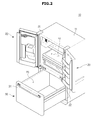
- FIG. 2 is a perspective view showing the inside of a refrigerator in accordance with one embodiment of the present disclosure.
- FIG. 3 is a view obtained by cutting the refrigerator of FIG. 1 by an A-A' section.
- a refrigerator 10 may include a main body 11, refrigerating compartment doors 20 and freezer compartment door 30 connected to the main body 11, and a cold air generating unit 200 that generates cold air.
- the main body 11 includes an external box 12 and an internal box 13.
- the external box 12 forms the appearance of the main body 11.
- the external box 12 may be made of a metallic material having durability and aesthetic sense and formed by press molding.
- the internal box 13 is provided on an inner side of the external box 12 to form the refrigerating compartment 50 and the freezer compartment 70.
- the internal box 13 may be formed by injection-molding a resin material, and injection-molded in one piece.
- a heat insulating material 14 may be provided between the internal box 13 and the external box 12.
- the heat insulating material 14 is filled between the internal box 13 and the external box 12 to prevent the leakage of cold air inside the refrigerating compartments 50 and the freezer compartment 70 and prevent the influx of external warm air.
- urethane foam may be used as an example of the heat insulating material 14.
- the refrigerating compartment 50 and the freezer compartment 70 are provided with opened front surfaces so as to take in and out food from the refrigerating compartment 50 and the freezer compartment 70.
- the refrigerating compartment 50 and the freezer compartment 70 may be partitioned by a partition wall 15.
- the refrigerating compartment 50 may be further partitioned into a refrigerating section 50a and an alternate temperature section 50b that can be set to have a different temperature from that of the refrigerating section 50a.
- the alternate temperature section 50b may be formed as a separate storage compartment as shown in FIGS. 1 to 3 .
- the refrigerator 10 maintains each of the refrigerating compartment 50 and the freezer compartment 70 at a target temperature which is set in advance.
- the target temperature refers to a temperature which is set to be maintained by each of the refrigerating compartment 50 and the freezer compartment 70, and the target temperature may be differently set for each of the refrigerating compartment 50 and the freezer compartment 70.
- the refrigerating compartment 50 may be maintained to have a temperature of approximately 3°C
- the freezer compartment 70 may be maintained to have a temperature of approximately -18°C.
- the alternate temperature section 50b of the refrigerating compartment 50 may be maintained to have a temperature of approximately -5°C to 1°C, unlike that of the refrigerating section 50a of the refrigerating compartment 50.
- the refrigerating compartment 50 may be provided with an opened front surface so as to take in and out the food from the refrigerating compartment 50, and the opened front surface may be opened and closed by a pair of refrigerating compartment doors 20 which can be rotatably coupled to the refrigerating compartment 50 by a hinge member 25.
- a refrigerating compartment door handle 21 may be provided on a front surface of the refrigerating compartment doors 20 in a vertical direction relative to the refrigerating compartment 50. A user may open the refrigerating compartment 50 by rotatably pulling the refrigerating compartment door 20 forward while gripping the refrigerating compartment door handle 21.
- the refrigerating compartment door 20 may adopt a heat insulating structure so as to prevent cold air inside the refrigerating compartment 50 from leaking, and prevent warm air outside the refrigerating compartment 50 from being introduced into the freezer compartment 70.
- an interface unit 310 of FIG. 1 may be provided on the front surface of the refrigerating compartment door 20.
- the interface unit 310 provides interaction between a user and the refrigerator 10.
- a door guard 22 behind which food may be stored may be provided on the rear surface of the refrigerating compartment door 20.
- the shelf 52 may be provided inside the refrigerating compartment 50, so it is possible to conveniently store food.
- the refrigerating compartment 50 may be partitioned into the refrigerating section 50a and the alternate temperature section 50b. That is, the alternate temperature section 50b may be separately partitioned inside the refrigerating compartment 50.
- the alternate temperature section 50b may be set to have the same target temperature as that of the refrigerating section 50a, but set to have a different target temperature from that of the refrigerating section 50a.
- the alternate temperature section 50b may be maintained to have a different temperature from those of the refrigerating section 50a and the freezer compartment 70.
- the alternate temperature section 50b be provided in such a manner that temperature transmission with the refrigerating section 50a or the freezer compartment 70 is prevented to minimize a loss due to heat exchange.
- the alternate temperature section 50b may be separately provided as a storage compartment in the bottom of the refrigerating compartment 50 in the form of a drawer.
- the alternate temperature section 50b may be partitioned with the refrigerating section 50a by a rectangular shaped-drawer 62 with one opened surface and a shelf 52.
- the rectangular shaped-drawer 62 may allow food accommodated in the alternate temperature section 50b to be easily pulled out.
- a first cold air supply unit 100 may be provided on the rear side of the refrigerating compartment 50.
- the first cold air supply unit 100 may supply cold air generated by the cold air generating unit 200 to the refrigerating compartment 50 so that the refrigerating section 50a and the alternate temperature section 50b can maintain to have the set target temperature.
- a first temperature sensor 51 for detecting the temperature of the refrigerating section 50a may be provided in the refrigerating section 50a
- a second temperature sensor 61 for detecting the temperature of the alternate temperature section 50b may be provided in the alternate temperature section 50b.
- the first temperature sensor 51 may be provided on a front surface of a first cover 120 as shown in FIG. 3
- the second temperature sensor 61 may be provided in the shelf 52, but they are not limited thereto.
- the first temperature sensor 51 may be provided in the shelf 52 or the second temperature sensor 61 may be provided in a lower end of the first cover 120.
- the refrigerator 10 may allow the refrigerating section 50a and the alternate temperature section 50b to maintain the set target temperature based on the first temperature sensor 51 and the second temperature sensor 61.
- the supply of cold air for maintaining the set target temperature of the refrigerating section 50a is referred to as a refrigerating operation
- the supply of cold air for maintaining the set target temperature of the alternate temperature section 50b is referred to as an alternate temperature operation.
- the first cold air supply unit 100 is provided in the refrigerating compartment 50.
- the first cold air supply unit 100 may provide cold air to the refrigerating compartment 50 so that the temperatures of the refrigerating section 50a and the alternate temperature section 50b may converge to the set target temperatures.
- the freezer compartment 70 may be provided with an opened front surface so as to store the food, and opened and closed so as to be slidably movable by a freezer compartment door 30.
- a freezer compartment door handle 31 for opening and closing the freezer compartment door 30 may be provided on the front surface of the freezer compartment door 30 in a lateral direction.
- a second cold air supply unit 150 may be provided on the rear side of the freezer compartment 70, and the freezer compartment 70 may be maintained to have a set target temperature by the second cold air supply unit 150.
- an operation for supplying cold air so that the freezer compartment 70 maintains the set target temperature is referred to as a freezing operation.
- a third temperature sensor 71 for detecting the temperature inside the freezer compartment 70 may be provided.
- the refrigerator 10 may further include a machine compartment 19.
- the machine compartment 19 may be provided in a lower portion of the main body 11 to provide a space that can accommodate compartments for the driving of the refrigerator 10.
- the machine compartment 19 may accommodate a compressor 210 and a condenser 220.
- FIGS. 1 to 3 a case in which the refrigerator 10 is a bottom freeze-type refrigerator in which the refrigerating compartment 50 is formed in the upper side of the refrigerator 10 and the freezer compartment 70 is formed in the lower side thereof as shown, but the present disclosure is not limited thereto.
- the present disclosure may be applied to the refrigerator 10 that is a side-by-side type refrigerator in which the refrigerating compartment 50 and the freezer compartment 70 are partitioned on the left side and the right side, a refrigerator 10 that is a top mount-type refrigerator, or a refrigerator 10 in which these are mixed.
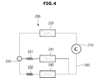
- FIG. 4 is a view illustrating the flow of a refrigerant in a cold air generating unit in accordance with one embodiment of the present disclosure.
- the cold air generating unit 200 generates cold air to be supplied to the refrigerating compartment 50 and the freezer compartment 70.
- the cold air generating unit 200 may include the compressor 210 compress a refrigerant to yield a compressed refrigerant, the condenser 220 to condense the refrigerant to yield a condensed refrigerant, a first capillary tube 231 and a second capillary tube 232 to expand the refrigerant, the first evaporator 241 and the second evaporator 242 to evaporate the refrigerant to generate cold air, and a refrigerant pipe 260 to guide the refrigerant.
- the compressor 210 may be installed in the machine compartment 19 provided in the lower portion of the main body 11 to compress the refrigerant into a high temperature and high pressure refrigerant using a rotational force of an electric motor or the like.
- the refrigerant may be compressed into a higher pressure refrigerant along with an increase in the rotational speed of the compressor 210.
- the evaporation in the first evaporator 241 and the second evaporator 242 may be further activated, so the cold air having a lower temperature may be generated.
- the condenser 220 may be installed in the machine compartment 19 provided in the lower portion of the main body 11.
- the refrigerant having been compressed into the high temperature and high pressure refrigerant is condensed while passing through the condenser 220.
- a fan may be disposed on one side of the condenser 220 to facilitate radiation of the compressed refrigerant.
- a flow path switching valve 250 may adjust a flow path of the condensed refrigerant.
- the first evaporator 241 and the second evaporator 242 to which the condensed refrigerant is supplied may be selected by adjusting the flow path switching valve 250, so it is possible to select the refrigerating compartment 50 and the freezer compartment 70 to which the cold air is to be supplied.
- the cold air may be supplied to the refrigerating compartment 50
- the cold air may be supplied to the freezer compartment 70.
- the freezer compartment 70 and the refrigerating compartment 50 may be simultaneously cooled.
- the flow path switching valve 250 may be implemented so as to be driven by an electromechanical force.
- the flow path switching valve 250 may be configured to be driven by a solenoid or a motor.
- the first capillary tube 231 and the second capillary tube 232 may create the refrigerant in a liquid state of low temperature and low pressure by expanding the condensed refrigerant. That is, the condensed refrigerant is expanded and becomes in the liquid state of low temperature and low pressure while passing through the first capillary tube 231 and the second capillary tube 232, and then moves to the first evaporator 241 and the second evaporator 242.
- the first evaporator 241 and the second evaporator 242 may cool ambient air while evaporating the refrigerant in the liquid state of low temperature and low pressure which has passed through the first capillary tube 231 and the second capillary tube 232, and thereby may generate the cold air.
- the refrigerant which has been completely evaporated is supplied to the compressor 210 again, so a cooling cycle is repeated.
- a defrost heater to remove, using heat, frost formed on the first evaporator 241 and the second evaporator 242 in a process of generating the cold air may be provided.
- roll-bond type evaporators that adopt a direct cooling system to exchange heat directly with air may be used.
- the roll-bond type evaporator may be provided in a platy form.
- the roll-bond type evaporator provided in the platy form may be disposed in the first cold air supply unit 100.
- FIG. 5 is a view showing a first evaporator provided in a refrigerator in accordance with one embodiment of the present disclosure.
- the first evaporator 241 in accordance with one embodiment of the present disclosure may have an inlet 2411 through which the refrigerant in the low-temperature and low-pressure state is introduced and an outlet 2413 through which the refrigerant having been circulated inside the first evaporator 241 is supplied to the compressor 210, and include a refrigerant flow path 2412 in which the refrigerant is exposed to the first cold air supply unit 100 to exchange heat while the refrigerant is circulated inside the first evaporator 241.
- the first evaporator 241 may be designed to have a planar shape.
- the refrigerant having been introduced through the inlet 2411 of the first evaporator 241 passes through the refrigerant flow path 2412 having various shapes and a predetermined length inside the first evaporator 241, and then flows to the outside through the outlet 2413.
- the refrigerant flow path 2412 of the first evaporator 241 may be formed into a multiple curved shape to further increase the heat exchange efficiency.
- the first cold air supply unit 100 and the second cold air supply unit 150 may supply the cold air generated by the cold air generating unit 200 to the refrigerating compartments 50 and the freezer compartment 70.
- the first cold air supply unit 100 supplies the cold air to the refrigerating compartment 50
- the second cold air supply unit 150 supplies the cold air to the freezer compartment 70.
- the first cold air supply unit 100 and the second cold air supply unit 150 will be described in detail.
- the first cold air supply unit 100 supplies cold air generated by the first evaporator 241 to the refrigerating section 50a and the alternate temperature section 50b.
- the first cold air supply unit 100 may include the first evaporator 241, the first cover 120, and a first circulation fan 130.
- the first cover 120 may be spaced apart from a rear surface 18 of the refrigerating section 50a by a predetermined distance to form the cold air flow path 110 through which the cold air generated by the first evaporator 241 is moved.
- a first passage 141 and a second passage 142 may be provided between the cold air flow path 110 and the refrigerating compartment 50.
- the first evaporator 241 may be disposed in the cold air flow path 110 formed by the first cover 120 and the rear surface 18 of the refrigerating compartment 50.
- the position in which the first evaporator 241 is disposed is not limited.
- the first evaporator 241 may be disposed between the first cover 120 and the rear surface 18 of the refrigerating compartment 50 to partition the cold air flow path 110.
- the cold air flow path 110 formed on the front surface is referred to as the front flow path 111
- the cold air flow path 110 formed on the rear surface is referred to as the rear flow path 112.
- the first cover 120 will be described in detail with reference to FIG. 6 .
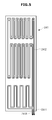
- FIG. 6 is a perspective view showing a first cover in accordance with one embodiment of the present disclosure.
- the first cover 120 may include a first plate 121, a second plate 122, and a third plate 123.
- the first plate 121 may be formed to extend downward from the top of the first cover 120.
- the first plate 121 may be provided in parallel to the rear surface 18 of the refrigerating compartment 50 in a state of being coupled to the refrigerating compartment 50.
- a first passage 141 may be provided above the first plate 121. Through the first passage 141, the cold air flow path 110 and the refrigerating section 50a may be connected to each other. That is, through the first passage 141, the cold air of the cold air flow path 110 may be introduced into the refrigerating section 50a.
- the second plate 122 extends to be bent forward from the bottom of the first plate 121 to connect the first plate 121 and the third plate 123.
- the third plate 123 may be provided to extend downward from the bottom of the second plate 122.
- the third plate 123 may be formed in parallel to the first plate 121.
- the third plate 123 may be connected to the second plate 122 which extends to be bent forward and positioned in front of the first plate 121.
- a second passage 142 may be formed in the third plate 123.
- the second passage 142 may be provided as a plurality of slots. Through the second passage 142, the cold air flow path 110 and the alternate temperature section 50b are connected to each other. That is, through the second passage 142, the cold air of the cold air flow path 110 may be introduced into the alternate temperature section 50b.
- one of the first passage 141 and the second passage 142 may be used as a discharge port, and the other one thereof may be used as an inlet port. This will be described in detail below.
- the first circulation fan 130 circulates the cold air.
- the first circulation fan 130 may allow the cold air of the cold air flow path 110 to flow, so the cold air generated in the first evaporator 241 is evenly supplied to the refrigerating compartment 50.
- the second cold air supply unit 150 supplies the cold air generated by the second evaporator 242 to the freezer compartment 70.
- the second cold air supply unit 150 may include the second evaporator 242, a second cover 157, and a second circulation fan 152.
- the second cover 157 may be provided between the rear surface of the freezer compartment 70 and the second evaporator 242. As shown in FIG. 3 , the second cover 157 may be provided in contact with the second evaporator 242, but provided to be spaced apart from the second evaporator 242 by a predetermined distance in the same manner as that in the first cover 120.
- the second circulation fan 152 may generate a flow of cold air inside the freezer compartment 70.
- FIG. 7 is a control block diagram illustrating the driving of a refrigerator in accordance with one embodiment of the present disclosure.
- the refrigerator 10 in accordance with one embodiment of the present disclosure includes the interface unit 310 to interact with a user, a sensor unit 320 to detect the state of each of the refrigerating compartment 50 and the freezer compartment 70, a storage unit 330 to store data associated with driving or operating the refrigerator 10, a control unit 350 to control the driving of the refrigerator 10, and a driving unit 340 to drive the cold air generating unit 200, and the first cold air supply unit 100 and the second cold air supply unit 150 in accordance with the control of the control unit 350.
- the interface unit 310 may include an input unit 311 and a display unit 312.
- the input unit 311 receives a control command that controls driving and/or operating of the refrigerator 10 from the user, and generates and outputs one or more electric signals corresponding to the input control command.
- the input unit 311 may include devices such as a touch sensor, a mouse, a keyboard, a joystick, buttons, a dial, a slider switch, and the like.
- the touch sensor is a device for detecting a touch input of a user and may use a capacitive technology, a resistive technology, an infrared technology, and a surface acoustic wave technology, but the present disclosure is not limited thereto. For example, any of technologies which have been already known or will be developed in the future may be used.
- the display unit 312 provides a variety of information associated with the refrigerator 10 to the user.
- the display unit 312 may provide setting information or driving state information of the refrigerator 10 to the user.
- the display unit 312 may be implemented as a plasma display panel, a liquid crystal display panel, a light-emitting diode panel, an organic light-emitting diode panel, or an active organic light-emitting panel, or an audio output means such as a speaker, but the present disclosure is not limited thereto.
- the display unit 312 and the input unit 311 may be integrally configured.
- the display unit 312 and the input unit 311 may be implemented as an integrated touch screen as shown in FIG. 1 . In this manner, when the display unit 312 and the input unit 311 are implemented as the touch screen, a user may interact with the refrigerator 10 using gestures.
- the sensor unit 320 may detect temperatures of the refrigerating compartment 50 and the freezer compartment 70.
- the sensor unit 320 may include the first temperature sensor 51 to detect, measure, or sense the temperature of the refrigerating section 50a, the second temperature sensor 61 to detect, measure, or sense the temperature of the alternate temperature section 50b, and the third temperature sensor 71 to detect, measure, or sense the temperature of the freezer compartment 70.
- the first temperature sensor 51, the second temperature sensor 61, and the third temperature sensor 71 may be implemented as a contact type temperature sensor or a non-contact type temperature sensor.
- the first temperature sensor 51, the second temperature sensor 61, and the third temperature sensor 71 may be implemented as an resistance temperature detector (RTD) temperature sensor using a resistance change of metal according to a temperature change, a thermistor temperature sensor using a semiconductor resistance change according to a temperature change, a thermocouple temperature sensor using an electromotive force generated at both ends of the junction of two different kinds of metal wires having different materials, and an integrated circuit (IC) temperature sensor using a voltage across both ends of a transistor which is changed according to the temperature or current-voltage characteristics of a P-N junction.
- RTD resistance temperature detector
- a thermistor temperature sensor using a semiconductor resistance change according to a temperature change
- a thermocouple temperature sensor using an electromotive force generated at both ends of the junction of two different kinds of metal wires having different materials
- IC integrated circuit
- the storage unit 330 may store a variety of information associated with the driving or the operations of the refrigerator 10.
- the storage unit 330 may store data such as firmware, application, and the like, directly for driving the refrigerator 10.
- the storage unit 330 may store temporary data generated by the driving of the refrigerator 10.
- the storage unit 330 may include a high-speed random access memory (RAM), a magnetic disk, a Static Random-Access Memory (S-RAM), a Dynamic Random-Access Memory (D-RAM), a Read-Only Memory (ROM), and the like, but is not limited thereto.
- the storage unit 330 may be detachably mounted to the refrigerator 10.
- the storage unit 330 may include a Compact Flash (CF) card, a Secure Digital (SD) card, a Smart Media (SM) card, a Multi-Media Card (MMC), or a memory stick.
- CF Compact Flash
- SD Secure Digital
- SM Smart Media
- MMC Multi-Media Card
- the driving unit 340 drives individual components of the refrigerator 10 in accordance with a control signal of the control unit 350.
- the driving unit 340 may be implemented as a driving circuit to drive the individual components such as the cold air generating unit 200, the first cold air supply unit 100, the second cold air supply unit 150, and the like, of the refrigerator 10.
- the control unit 350 generally controls the operations of the refrigerator 10.
- the control unit 350 may correspond to one or a plurality of processors.
- the processor may be implemented as an array of a plurality of logic gates, or implemented as a combination of a general-purpose microprocessor and a memory in which a program being executable in the microprocessor is stored.
- the control unit 350 may control a cooling operation so that the target temperature of each of the refrigerating compartment 50 and the freezer compartment 70 can be maintained. That is, the cooling operation refers to the supply of the cold air so that the actual temperature of each of the refrigerating compartment 50 and the freezer compartment 70 converges to the target temperature.
- the actual temperature refers to a temperature measured by each of the first temperature sensor 51, the second temperature sensor 61, and the third temperature sensor 71
- the target temperature refers to a temperature to be maintained by each of the refrigerating compartment 50 and the freezer compartment 70.
- the cooling operation may include a refrigerating operation and a freezing operation.
- the operation of the refrigerator 10 will be described in detail.
- FIG. 8 is a schematic view showing the cooling operation of the refrigerator 10 of FIG. 1 in accordance with one embodiment of the present disclosure.
- the control unit 350 detects the temperature of each of the refrigerating compartment 50 and the freezer compartment 70.
- the temperature of each of the refrigerating compartment 50 and the freezer compartment 70 may be consecutively detected, for example, at a predetermined period.
- the control unit 350 detects the temperature of the refrigerating section 50a via the first temperature sensor 51, detects the temperature of the alternate temperature section 50b via the second temperature sensor 61, and detects the temperature of the freezer compartment 70 via the third temperature sensor 71.
- the control unit 350 compares whether the detected temperature is higher than the target temperature.
- the target temperature may be differently set for the refrigerating compartment 50 and the freezer compartment 70.
- the refrigerating section 50a may be set to have a target temperature of approximately 3°C
- the freezer compartment 70 may be set to have a target temperature of approximately -18°C
- the alternate temperature section 50b may be set to have a target temperature of approximately -5°C to 1°C.
- the temperature of the alternate temperature section 50b is set to be lower than the temperature of the refrigerating section 50a.
- the control unit 350 When the detected temperature is higher than the target temperature (YES path of operation S503), the control unit 350 starts an operation for supplying cold air.
- the refrigerator 10 in accordance with one embodiment is capable of independent cooling, and the control unit 350 may control the cold air to be supplied to only the refrigerating compartment 50 and the freezer compartment 70 in which the detected temperature is higher than the target temperature.
- the control unit 350 may perform a freezing operation.
- the cooling operation when the temperature of the refrigerating compartment 50 is lower than the target temperature will be described with reference to FIGS. 9 to 11 .
- FIG. 9 illustrates an example of the operation of the refrigerator 10 in accordance with one embodiment of the present disclosure.
- FIG. 9 illustrates the cooling operation when the target temperature of the alternate temperature section 50b is lower than the target temperature of the refrigerating section 50a.
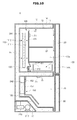
- FIG. 10 illustrates the flow of cold air in a refrigerating operation section
- FIG. 11 illustrates the flow of cold air in an alternate temperature operation section.
- the refrigerator 10 may perform a refrigerating operation T1 for supplying the cold air to the refrigerating compartment 50 and an alternate temperature operation T2 for supplying the cold air to the alternate temperature section 50b.
- the control unit 350 may switch the compressor 210 into a turn-on state to operate a cooling cycle of compression, condensation, expansion, and evaporation.
- the compressor 210 may be rotated at a preset rotational speed. In this instance, the rotational speed of the compressor may be different according to a temperature error of the refrigerating compartment 50 and the freezer compartment 70. For example, as the actual temperature of each of the refrigerating compartment 50 and the freezer compartment 70 drops below the target temperature of each of the refrigerating compartment 50 and the freezer compartment 70, the compressor 210 may operate at a higher speed.
- control unit 350 may supply the cold air to the cold air flow path 110 of the first cold air supply unit 100 by opening the flow path switching valve 250 towards the first evaporator 241.
- the refrigerant is compressed by the rotational force of the compressor 210, and the compressed refrigerant is condensed by the condenser 220.
- the condensed refrigerant is expanded in the first capillary tube 231 and introduced into the first evaporator 241 in a liquid state of low temperature and low pressure.
- the refrigerant having been introduced into the first evaporator 241 may cool the air of the cold air flow path 110 of the first cold air supply unit 100 to generate the cold air while it evaporates.
- the control unit 350 switches the first circulation fan 130 into a turn-on state in order to facilitate the circulation of the cold air.
- the first circulation fan 130 may be rotated at a predetermined rotational speed.
- the cold air generated by the first evaporator 241 may flow as shown in FIG. 10 .
- the air of the alternate temperature section 50b may be introduced through the second passage 142 by a suction force generated by the first circulation fan 130.
- the air introduced through the second passage 142 rises along the cold air flow path 110 due to a pressure difference.
- the rising air is cooled by the first evaporator 241 and discharged to the refrigerating section 50a through the first passage 141.
- the cold air having been discharged to the first passage 141 in this manner cools the refrigerating section 50a and the alternate temperature section 50b while it is circulated in the refrigerating section 50a and the alternate temperature section 50b, and then is introduced into the second passage 142 again.
- the control unit 350 terminates the refrigerating operation T1.
- the control unit 350 starts the alternate temperature operation T2.
- the cold air may flow in the clockwise direction by the first circulation fan 130 as shown in FIG. 10 , so that the temperature of the refrigerating section 50a to which the cold air is directly supplied becomes relatively lower than the temperature of the alternate temperature section 50b.
- the control unit 350 may perform the alternate temperature operation T2 so that the alternate temperature section 50b maintains a lower temperature than that of the refrigerating section 50a, and thereby may additionally cool the alternate temperature section 50b.
- the alternate temperature section 50b may be cooled by deflection of the cold air.
- the control unit 350 switches the first circulation fan 130 into a turn-off state so that the cold air of the cold air flow path 110 can be introduced into the alternate temperature section 50b by the deflection of the cold air.
- the first circulation fan 130 stops, the flow of the cold air caused by the first circulation fan 130 is stopped, and therefore the cold air of the cold air flow path 110 having been cooled by the first evaporator 241 moves in the downward direction by a convection phenomenon, as shown in FIG. 11 .
- the cold air having moved to below the cold air flow path 110 in this manner is introduced into the alternate temperature section 50b via the second passage 142, and thereby cools the alternate temperature section 50b.
- the control unit 350 switches the compressor 210 into a turn-off state to terminate the cooling operation.
- control unit 350 may maximize the deflection of the cold air by controlling the compressor 210 to be rotated at a higher speed.
- the compressor 210 compresses the refrigerant at a higher pressure along with an increase in the rotational speed of the compressor 210.
- the surface temperature of the first evaporator 241 is further decreased.
- the control unit 350 may drive the compressor at 1400 revolutions per minute (RPM) upon the refrigerating operation and drive the compressor at 1800 RPM upon the alternate temperature operation, thereby maximizing the deflection of the cold air upon the alternate temperature operation.
- RPM revolutions per minute
- the first circulation fan 130 may be rotated in the opposite direction to that in the refrigerating operation T1 to facilitate the introduction of the cold air into the alternate temperature section 50b.
- driving an additional fan or damper for the cooling of the alternate temperature section 50b may become optional, and thereby may increase the cooling efficiency of the alternate temperature section 50b.
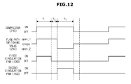
- FIG. 12 illustrates an example of a cooling operation of a refrigerator in accordance with one embodiment of the present disclosure
- FIG. 13 is a view illustrating the flow of cold air in a freezing operation section of FIG. 12 .
- the refrigerator may sequentially carry out the refrigerating operation T1, the alternate temperature operation T2, and a freezing operation T3.
- the control unit 350 first starts the refrigerating operation T1.
- the control unit 350 switches the compressor 210 into a turn-on state so the cooling cycle starts, controls the flow path switching valve 250 to be opened towards the first evaporator 241, and switches the first circulation fan 130 into an ON state.
- the cold air is generated in the cold air flow path 110 by the first evaporator 241, and the generated cold air of the cold air flow path 110 flows by the first circulation fan 130 as shown in FIG. 10 , and thereby cools the refrigerating compartment 50 while it is circulated via the first passage 141, the refrigerating section 50a, the alternate temperature section 50b, and the second passage 142 in the stated order.
- control unit 350 may terminate the refrigerating operation T1 and start the alternate temperature operation T2.
- the alternate temperature operation T2 starts, the first circulation fan 130 is switched into an OFF state.
- the cold air of the cold air flow path 110 having been cooled by the first evaporator 241 is moved towards the second passage 142 by convection.
- the cold air having been moved towards the second passage 142 is supplied to the alternate temperature section 50b via the second passage 142.
- the alternate temperature section 50b is further cooled by the cold air having been supplied via the second passage 142, and therefore the temperature of the alternate temperature section 50b becomes lower than the temperature of the refrigerating section 50a. That is, by the deflection of the cold air of the cold air flow path 110, the alternate temperature section 50b is further cooled.
- the control unit 350 may terminate the alternate temperature operation T2 and start the freezing operation T3.
- the control unit 350 may open the flow path switching valve 250 towards the second evaporator 242, and switch the second circulation fan 152 into a turn-on state.
- the air around the second cold air supply unit 150 is cooled by the second evaporator 242 so the cold air is generated, and the cold air is circulated inside the freezer compartment 70 by the second circulation fan 152.
- the control unit 350 terminates the freezing operation T3. Specifically, the control unit switches the compressor 210 into a turn-off state, so that the operation of the compressor 210 is stopped and the flow path switching valve 250 is closed. In addition, it is possible to switch both the first circulation fan 130 and the second circulation fan 152 into a turn-off state.
- the cooling operation may further include an operation for the recovery of the refrigerant.
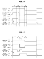
- FIG. 14 illustrates an example of a refrigerant recovery operation
- FIG. 15 illustrates another example of a refrigerant recovery operation.
- the control unit 350 drives the second circulation fan 152 during the preset time T4 together with the start of the refrigerating operation T1.
- the second circulation fan 152 is driven during the preset time T4 in this manner, the refrigerant remaining the second evaporator 242 is introduced into the compressor 210 again while being evaporated, thereby increasing the efficiency of the refrigerating operation T1.
- the control unit may drive the first circulation fan 130 and the second circulation fan 152 during the preset time to recover the refrigerant remaining in the first evaporator 241 and the second evaporator 242 to the compressor 210.
- the control unit 350 may perform a refrigerant recovery operation during a preset time T5 as shown in FIG. 15 .
- the control unit 350 further drives the second circulation fan 152 during the preset time T5, and then turns off the second circulation fan 152.
- the second circulation fan 152 is driven during the preset time T5 in this manner, the refrigerant remaining in the second evaporator 242 may be introduced into the compressor 210 again while being evaporated, so that it is possible to recover the remaining refrigerant and additionally cool the freezer compartment 70 using the refrigerant remaining in the second evaporator 242.
- FIG. 16 illustrates another example of a cooling operation of a refrigerator in accordance with one embodiment of the present disclosure.
- the control unit 350 first starts the refrigerating operation T1.
- the compressor 210 is switched into an ON state so the cooling cycle is started, the flow path switching valve 250 is opened toward the first evaporator 241 so the cold air is generated in the cold air flow path 110, and the first circulation fan 130 is driven so the cold air of the cold air flow path 110 is circulated as shown in FIG. 10 .
- the second circulation fan 152 is driven during the preset time T4 together with the start of the refrigerating operation T1, so it is possible to recover the refrigerant remaining in the second evaporator 242.
- the control unit 350 terminates the refrigerating operation T1 and starts the freezing operation T3. Specifically, the control unit 350 opens the flow path switching valve 250 towards the second evaporator 242 so that the refrigerant is supplied to the second evaporator 242, and supplies the cold air to the second cold air supply unit 150. In addition, the control unit 350 switches the second circulation fan 152 into a turn-on state to circulate the cold air generated by the second evaporator 242. In this instance, the circulation of the cold air occurs in the freezer compartment 70 by the second circulation fan 152 as shown in FIG. 13 .
- the first circulation fan 130 may be turned off, but, the first circulation fan 130 may be continuously driven as shown in FIG. 16 .
- the first circulation fan 130 is driven in this manner, so that it is possible to recover the refrigerant remaining in the first evaporator 241 and prevent the occurrence of frost in the first evaporator 241.
- the control unit 350 may perform the freezing operation T3 during the preset time, and then perform the alternate temperature operation T2.
- the freezing operation T3 is switched into the alternate temperature operation T2
- the flow path switching valve 250 is opened towards the first evaporator 241, and the driving of the first circulation fan 130 is switched into a turn-off state. Due to the deflection of the cold air caused by the convection phenomenon as shown in FIG. 11 , the cold air of the cold air flow path 110 is introduced into the alternate temperature section 50b so the alternate temperature section 50b is cooled.
- the control unit 350 may switch the second circulation fan 152 into the turn-off state, but the present disclosure is not limited thereto.
- the second circulation fan 152 may be continuously driven even during the alternate temperature operation T2, or continuously driven during the preset time after the alternate temperature operation T2 is started.
- the second circulation fan 152 is driven even upon the alternate temperature operation T2 in this manner, the occurrence of frost in the second evaporator 242 may be prevented, and the refrigerant remaining in the second evaporator 242 may be recovered to the compressor 210 again, so that the refrigerator 10 may be more efficiently cooled.
- the control unit 350 may start the freezing operation T3 again.
- the freezing operation T3 is started again, the flow path switching valve 250 is opened towards the second evaporator 242 again, and the second circulation fan 152 is switched into the turn-on state again.
- the circulation of the cold air occurs upon the freezing operation T3 as shown in FIG. 13 .
- the control unit 350 terminates the freezing operation T3. Specifically, the operation of the compressor 210 is stopped, and the flow path switching valve 250 is closed. In this instance, the second circulation fan 152 may be further driven during the preset time T5 after the termination of the freezing operation T3.
- the refrigerator 10 may open all the flow path switching valves 250 to simultaneously perform the refrigerating operation T1 and the freezing operation T3.
- the cooling operation of the refrigerator in accordance with one embodiment of the present disclosure may be modified into various methods for efficiently maintaining the temperature of each of the refrigerating compartment 50 and the freezer compartment 70.
- still another example of the cooling operation will be described in detail with reference to FIG. 17 .
- the refrigerator 10 may sequentially perform the refrigerating operation T1, the alternate temperature operation T2, and the freezing operation T3 to cool the refrigerating compartment 50 and the freezer compartment 70.
- the control unit 350 switches the compressor 210 into an ON state upon the refrigerating operation T1, the alternate temperature operation T2, and the freezing operation T3 for the cooling of the refrigerating compartment 50 and the freezer compartment 70.
- the compressor 210 When the compressor 210 is turned on, the cooling cycle in which the refrigerant is compressed, condensed, expanded, and evaporated is operated so the cold air is generated.
- control unit 350 may determine the refrigerating compartment 50 and the freezer compartment 70 to which the cold air is to be supplied, by adjusting the flow path switching valve 250 during the operation of the cooling cycle. In addition, the control unit 350 may adjust the circulation of the cold air by controlling the driving of each of the first circulation fan 130 and the second circulation fan 152.
- the compressor 210 is switched into the ON state so the cooling cycle is started.
- the flow path switching valve 250 is opened (open_1) towards the first evaporator 241.
- cold air is generated in the cold air flow path 110 while the condensed refrigerant is evaporated.
- the first circulation fan 130 is switched into the ON state to allow the cold air generated by the first evaporator 241 to flow. Specifically, when the first circulation fan 130 is driven, the cold air of the cold air flow path 110 is circulated while being rotated in the clockwise direction, as shown in FIG. 10 . That is, the cold air of the cold air flow path 110 is discharged to the first passage 141 by the first circulation fan 130 to sequentially cool the refrigerating section 50a and the alternate temperature section 50b, and is introduced into the cold air flow path 110 through the second passage 142 again.
- the second circulation fan 152 may be driven during the preset time T4, so it is possible to recover the refrigerant remaining in the second evaporator 242 to the compressor 210 again.
- the second circulation fan 152 is driven at the beginning of the refrigerating operation T1 in this manner, the refrigerant remaining in the second evaporator 242 is introduced into the compressor 210 again while being evaporated, thereby increasing the cooling efficiency.
- the control unit 350 may terminate the refrigerating operation T1 and start the alternate temperature operation T2.
- the target temperature of the alternate temperature section 50b is set to be lower than the target temperature of the refrigerating section 50a, the additional cooling may be demanded in the alternate temperature section 50b.
- the alternate temperature section 50b may be cooled to the lower temperature through the alternate temperature operation T2.
- the control unit 350 switches the first circulation fan 130 into the turn-off state.
- the cold air of the cold air flow path 110 may cause natural convection. By such a convection phenomenon, the cold air of the cold air flow path 110 may be deflected downward.
- the deflected cold air is introduced into the alternate temperature section 50b through the second passage 142 to cool the alternate temperature section 50b.
- the control unit 350 may compress the refrigerant at the higher pressure by increasing the rotational speed of the compressor 210, so that the deflection of the cold air of the cold air flow path 110 may be maximized.
- the control unit 350 may terminate the alternate temperature operation T2 and start the freezing operation T3. Specifically, the control unit 350 may change the flow of the refrigerant to the direction of the second evaporator 242 by adjusting the flow path switching valve 250, and switch the second circulation fan 152 into the ON state.
- the flow path switching valve 250 is opened (open_2) towards the second evaporator 242.
- the cold air generated while the refrigerant having been introduced into the second evaporator 242 is evaporated may cool the freezer compartment 70 while being circulated inside the freezer compartment 70 by the second circulation fan 152.
- the control unit may drive the first circulation fan 130 during a preset time T6 after the refrigerant supply to the first evaporator 241 is stopped.
- the first circulation fan 130 is driven during the preset time T6 in this manner, the refrigerant remaining in the first evaporator 241 may be introduced into the compressor 210 again while being evaporated, and therefore it is possible to recover the refrigerant remaining in the first evaporator 241.
- the control unit 350 terminates the freezing operation T3. Specifically, the driving of the compressor 210 is stopped, and the flow path switching valve 250 is closed.
- the second circulation fan 152 may be further driven during the preset time T5 after the termination of the freezing operation T3, so it is possible to recover the remaining refrigerant of the second evaporator 242.
- the first cold air supply unit 100 may be modified into various types. Hereinafter, another type of the first cold air supply unit 100 will be described in detail with reference to FIG. 18 .
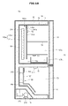
- FIG. 18 shows a refrigerator in accordance with another embodiment of the present disclosure.
- a refrigerator 10a includes a first cold air supply unit 100a in which a cold air flow path 110a is provided.
- the first cold air supply unit 100a includes a first cover 120a.
- the first cover 120a is provided forward from the rear surface 18 of the refrigerating compartment 50 to form the cold air flow path 110a.
- the first cover 120a may be provided without bending as shown in FIG. 18 .
- the first cover 120a may be provided downward from the ceiling of the refrigerating compartment 50 to form a first passage 141a. That is, the first passage 141a is formed between the ceiling of the refrigerating compartment 50 and the upper surface of the first cover 120a.
- first cover 120a may be provided upward from the bottom of the refrigerating section 50a to form a second passage 142a. That is, the second passage 142a is formed between the bottom of the refrigerating section 50a and the lower surface of the first cover 120a.
- a first circulation fan 130a may be provided in the position corresponding to the first passage 141a.
- the first circulation fan 130a may be rotated in the opposite direction to that in the first circulation fan 130 shown in FIG. 3 to allow the cold air to flow. That is, the first circulation fan 130a may draw the cold air of the cold air flow path 110a and discharge the drawn cold air to the refrigerating section 50a to allow the cold air to flow.
Landscapes
- Engineering & Computer Science (AREA)
- Chemical & Material Sciences (AREA)
- Combustion & Propulsion (AREA)
- Physics & Mathematics (AREA)
- Mechanical Engineering (AREA)
- Thermal Sciences (AREA)
- General Engineering & Computer Science (AREA)
- Cold Air Circulating Systems And Constructional Details In Refrigerators (AREA)
- Devices That Are Associated With Refrigeration Equipment (AREA)
Applications Claiming Priority (1)
| Application Number | Priority Date | Filing Date | Title |
|---|---|---|---|
| KR1020140169782A KR102267881B1 (ko) | 2014-12-01 | 2014-12-01 | 냉장고 |
Publications (1)
| Publication Number | Publication Date |
|---|---|
| EP3029399A1 true EP3029399A1 (de) | 2016-06-08 |
Family
ID=54770926
Family Applications (1)
| Application Number | Title | Priority Date | Filing Date |
|---|---|---|---|
| EP15197222.1A Withdrawn EP3029399A1 (de) | 2014-12-01 | 2015-12-01 | Kühlschrank |
Country Status (4)
| Country | Link |
|---|---|
| US (1) | US10429118B2 (de) |
| EP (1) | EP3029399A1 (de) |
| KR (1) | KR102267881B1 (de) |
| CN (1) | CN105650969B (de) |
Cited By (1)
| Publication number | Priority date | Publication date | Assignee | Title |
|---|---|---|---|---|
| EP3732413A4 (de) * | 2017-12-25 | 2021-10-06 | Arçelik Anonim Sirketi | Kühler mit einem durch wärme gesteuerten sonderfach |
Families Citing this family (23)
| Publication number | Priority date | Publication date | Assignee | Title |
|---|---|---|---|---|
| US10612832B2 (en) * | 2015-12-17 | 2020-04-07 | Samsung Electronics Co., Ltd. | Refrigerator with defrost operation control |
| CN106568269B (zh) * | 2016-10-24 | 2019-08-27 | 青岛海尔股份有限公司 | 冰箱 |
| KR102204008B1 (ko) * | 2016-11-30 | 2021-01-18 | 엘지전자 주식회사 | 냉장고 |
| KR102292004B1 (ko) * | 2017-04-11 | 2021-08-23 | 엘지전자 주식회사 | 냉장고 |
| KR102320765B1 (ko) * | 2017-05-26 | 2021-11-03 | 엘지전자 주식회사 | 냉장고 |
| CN107024062B (zh) * | 2017-05-31 | 2020-07-28 | 青岛海尔股份有限公司 | 一种冰箱及其控制方法 |
| KR102418005B1 (ko) * | 2017-08-28 | 2022-07-07 | 삼성전자주식회사 | 냉장고 및 그 제어방법 |
| WO2019088715A1 (en) | 2017-11-01 | 2019-05-09 | Samsung Electronics Co., Ltd. | Refrigerator |
| CN108050747A (zh) * | 2017-12-13 | 2018-05-18 | 合肥华凌股份有限公司 | 平均冷藏室温度的控制方法、控制系统及制冷设备 |
| JP6975657B2 (ja) * | 2018-02-08 | 2021-12-01 | 日立グローバルライフソリューションズ株式会社 | 冷蔵庫 |
| CN108662832B (zh) * | 2018-06-19 | 2022-09-13 | 长虹美菱股份有限公司 | 一种具有瞬冷功能的保鲜冰箱及其控制方法 |
| KR102619556B1 (ko) * | 2018-12-19 | 2024-01-02 | 삼성전자주식회사 | 냉장고 |
| EP3943845B1 (de) * | 2019-03-22 | 2025-05-07 | LG Electronics Inc. | Kühlschrank |
| CN112444036B (zh) * | 2019-09-04 | 2023-07-07 | 青岛海尔特种电冰柜有限公司 | 一种送风装置顶置的多温区酒柜 |
| EP3819568B1 (de) * | 2019-11-05 | 2025-05-21 | Electrolux Appliances Aktiebolag | Kühlschrank |
| CN112971394B (zh) * | 2019-12-12 | 2023-04-11 | 青岛海尔特种电冰柜有限公司 | 一种双温区恒温恒湿酒柜控制方法及双温区恒温恒湿酒柜 |
| CN113057452B (zh) * | 2019-12-31 | 2023-10-10 | 青岛海尔特种电冰柜有限公司 | 一种酒柜及其温湿度控制方法 |
| CN113074502A (zh) * | 2020-01-06 | 2021-07-06 | 青岛海尔电冰箱有限公司 | 制冷模组及冰箱 |
| KR20220105711A (ko) * | 2021-01-20 | 2022-07-28 | 엘지전자 주식회사 | 냉장고 및 냉장고의 제어 방법 |
| KR20220132305A (ko) | 2021-03-23 | 2022-09-30 | 삼성전자주식회사 | 냉장고 및 그 제어 방법 |
| US11940169B2 (en) * | 2022-01-05 | 2024-03-26 | Haier Us Appliance Solutions, Inc. | Air conditioner with thermostat setpoint estimation |
| CN115096030B (zh) * | 2022-05-13 | 2024-12-17 | 北京小米移动软件有限公司 | 一种温度控制结构及冰箱 |
| JP2025109473A (ja) * | 2024-01-12 | 2025-07-25 | 日立グローバルライフソリューションズ株式会社 | 冷蔵庫 |
Citations (6)
| Publication number | Priority date | Publication date | Assignee | Title |
|---|---|---|---|---|
| US3009338A (en) * | 1959-10-01 | 1961-11-21 | Westinghouse Electric Corp | Refrigeration apparatus |
| US3075366A (en) * | 1961-03-23 | 1963-01-29 | Westinghouse Electric Corp | Refrigerator air flow arrangement |
| US20070068180A1 (en) * | 2005-09-28 | 2007-03-29 | Samsung Electronics Co., Ltd. | Refrigerator and method for controlling the same |
| US20070209374A1 (en) * | 2001-12-13 | 2007-09-13 | Bsh Bosch Und Siemens Hausgerate Gmbh | Refrigerator with regulable dehumidification |
| EP2096389A2 (de) * | 2008-02-26 | 2009-09-02 | Liebherr-Hausgeräte Lienz GmbH | Kühl- und/oder Gefriergerät |
| US20130111933A1 (en) * | 2011-11-08 | 2013-05-09 | Korea University Research And Business Foundation | Refrigerator using non-azeotropic refrigerant mixture and control method thereof |
Family Cites Families (10)
| Publication number | Priority date | Publication date | Assignee | Title |
|---|---|---|---|---|
| US3169383A (en) * | 1958-11-25 | 1965-02-16 | Whirlpool Co | Refrigerator with hollow cold shelf |
| US3077749A (en) * | 1960-11-30 | 1963-02-19 | Westinghouse Electric Corp | Refrigerator air flow arrangement |
| KR19980030890A (ko) | 1996-10-30 | 1998-07-25 | 배순훈 | 냉장고 쿡칠(Cook-chill) 시스템 |
| KR19990056249A (ko) | 1997-12-29 | 1999-07-15 | 전주범 | 세미 간냉식 냉장고 |
| TW418309B (en) * | 1998-02-20 | 2001-01-11 | Matsushita Refrigeration | Refrigerator |
| TW446106U (en) * | 1998-02-20 | 2001-07-11 | Matsushita Refrigeration Co Lt | Refrigerator having a cooler mounted in each of a refrigerator compartment and a freezer compartment |
| US6931870B2 (en) * | 2002-12-04 | 2005-08-23 | Samsung Electronics Co., Ltd. | Time division multi-cycle type cooling apparatus and method for controlling the same |
| KR20040063392A (ko) * | 2003-01-07 | 2004-07-14 | 엘지전자 주식회사 | 국부 집중 냉각기능을 구비한 냉장고 |
| JP2006078050A (ja) | 2004-09-08 | 2006-03-23 | Matsushita Electric Ind Co Ltd | 冷蔵庫 |
| KR20080003660A (ko) | 2006-07-03 | 2008-01-08 | 주식회사 대우일렉트로닉스 | 온도 전환실을 갖는 냉장고 |
-
2014
- 2014-12-01 KR KR1020140169782A patent/KR102267881B1/ko not_active Expired - Fee Related
-
2015
- 2015-12-01 US US14/955,842 patent/US10429118B2/en active Active
- 2015-12-01 EP EP15197222.1A patent/EP3029399A1/de not_active Withdrawn
- 2015-12-01 CN CN201510864636.5A patent/CN105650969B/zh not_active Expired - Fee Related
Patent Citations (6)
| Publication number | Priority date | Publication date | Assignee | Title |
|---|---|---|---|---|
| US3009338A (en) * | 1959-10-01 | 1961-11-21 | Westinghouse Electric Corp | Refrigeration apparatus |
| US3075366A (en) * | 1961-03-23 | 1963-01-29 | Westinghouse Electric Corp | Refrigerator air flow arrangement |
| US20070209374A1 (en) * | 2001-12-13 | 2007-09-13 | Bsh Bosch Und Siemens Hausgerate Gmbh | Refrigerator with regulable dehumidification |
| US20070068180A1 (en) * | 2005-09-28 | 2007-03-29 | Samsung Electronics Co., Ltd. | Refrigerator and method for controlling the same |
| EP2096389A2 (de) * | 2008-02-26 | 2009-09-02 | Liebherr-Hausgeräte Lienz GmbH | Kühl- und/oder Gefriergerät |
| US20130111933A1 (en) * | 2011-11-08 | 2013-05-09 | Korea University Research And Business Foundation | Refrigerator using non-azeotropic refrigerant mixture and control method thereof |
Cited By (1)
| Publication number | Priority date | Publication date | Assignee | Title |
|---|---|---|---|---|
| EP3732413A4 (de) * | 2017-12-25 | 2021-10-06 | Arçelik Anonim Sirketi | Kühler mit einem durch wärme gesteuerten sonderfach |
Also Published As
| Publication number | Publication date |
|---|---|
| US20160153694A1 (en) | 2016-06-02 |
| US10429118B2 (en) | 2019-10-01 |
| CN105650969A (zh) | 2016-06-08 |
| KR20160065593A (ko) | 2016-06-09 |
| KR102267881B1 (ko) | 2021-06-23 |
| CN105650969B (zh) | 2018-11-13 |
Similar Documents
| Publication | Publication Date | Title |
|---|---|---|
| US10429118B2 (en) | Refrigerator | |
| US10190813B2 (en) | Refrigerator and method for controlling the same | |
| EP2988081B1 (de) | Kühlschrank | |
| US10302345B2 (en) | Refrigerator | |
| CN104220826B (zh) | 用于制冷设备的制冰机 | |
| US10036586B2 (en) | Refrigerator | |
| US11732958B2 (en) | Refrigerator and method of controlling a refrigerator | |
| US20110167862A1 (en) | Refrigeration and ice-making system thereof | |
| KR20160109521A (ko) | 냉장고 | |
| KR102747193B1 (ko) | 냉장고 및 그 제어방법 | |
| US11421934B2 (en) | Refrigerator and method of controlling a refrigerator | |
| US9377235B2 (en) | Refrigerator and control method for the same | |
| US11280533B2 (en) | Refrigerator and method of controlling the same | |
| CN101484764B (zh) | 具有温控室的冰箱 | |
| CN110352326B (zh) | 自动制冰机及冷藏冷冻箱 | |
| AU2016432230A1 (en) | Ice-making device and refrigerator | |
| EP3732413B1 (de) | Kühler mit einem durch wärme gesteuerten sonderfach | |
| US12474102B2 (en) | Refrigerator | |
| KR100913142B1 (ko) | 냉장고 및 그의 제어방법 | |
| JP2022165184A (ja) | 冷蔵庫 |
Legal Events
| Date | Code | Title | Description |
|---|---|---|---|
| PUAI | Public reference made under article 153(3) epc to a published international application that has entered the european phase |
Free format text: ORIGINAL CODE: 0009012 |
|
| 17P | Request for examination filed |
Effective date: 20151201 |
|
| AK | Designated contracting states |
Kind code of ref document: A1 Designated state(s): AL AT BE BG CH CY CZ DE DK EE ES FI FR GB GR HR HU IE IS IT LI LT LU LV MC MK MT NL NO PL PT RO RS SE SI SK SM TR |
|
| AX | Request for extension of the european patent |
Extension state: BA ME |
|
| STAA | Information on the status of an ep patent application or granted ep patent |
Free format text: STATUS: EXAMINATION IS IN PROGRESS |
|
| 17Q | First examination report despatched |
Effective date: 20181211 |
|
| GRAP | Despatch of communication of intention to grant a patent |
Free format text: ORIGINAL CODE: EPIDOSNIGR1 |
|
| STAA | Information on the status of an ep patent application or granted ep patent |
Free format text: STATUS: GRANT OF PATENT IS INTENDED |
|
| INTG | Intention to grant announced |
Effective date: 20230110 |
|
| STAA | Information on the status of an ep patent application or granted ep patent |
Free format text: STATUS: THE APPLICATION IS DEEMED TO BE WITHDRAWN |
|
| 18D | Application deemed to be withdrawn |
Effective date: 20230523 |