EP3029653A1 - Système et procédé pour afficher des repères de configuration conforme prédictif pour l'exécution d'un palier - Google Patents
Système et procédé pour afficher des repères de configuration conforme prédictif pour l'exécution d'un palier Download PDFInfo
- Publication number
- EP3029653A1 EP3029653A1 EP15196390.7A EP15196390A EP3029653A1 EP 3029653 A1 EP3029653 A1 EP 3029653A1 EP 15196390 A EP15196390 A EP 15196390A EP 3029653 A1 EP3029653 A1 EP 3029653A1
- Authority
- EP
- European Patent Office
- Prior art keywords
- aircraft
- display
- landing
- lift
- drag ratio
- Prior art date
- Legal status (The legal status is an assumption and is not a legal conclusion. Google has not performed a legal analysis and makes no representation as to the accuracy of the status listed.)
- Ceased
Links
Images




Classifications
-
- B—PERFORMING OPERATIONS; TRANSPORTING
- B64—AIRCRAFT; AVIATION; COSMONAUTICS
- B64D—EQUIPMENT FOR FITTING IN OR TO AIRCRAFT; FLIGHT SUITS; PARACHUTES; ARRANGEMENT OR MOUNTING OF POWER PLANTS OR PROPULSION TRANSMISSIONS IN AIRCRAFT
- B64D45/00—Aircraft indicators or protectors not otherwise provided for
- B64D45/04—Landing aids; Safety measures to prevent collision with earth's surface
-
- G—PHYSICS
- G08—SIGNALLING
- G08G—TRAFFIC CONTROL SYSTEMS
- G08G5/00—Traffic control systems for aircraft
- G08G5/50—Navigation or guidance aids
- G08G5/55—Navigation or guidance aids for a single aircraft
-
- G—PHYSICS
- G08—SIGNALLING
- G08G—TRAFFIC CONTROL SYSTEMS
- G08G5/00—Traffic control systems for aircraft
- G08G5/20—Arrangements for acquiring, generating, sharing or displaying traffic information
- G08G5/21—Arrangements for acquiring, generating, sharing or displaying traffic information located onboard the aircraft
-
- G—PHYSICS
- G08—SIGNALLING
- G08G—TRAFFIC CONTROL SYSTEMS
- G08G5/00—Traffic control systems for aircraft
- G08G5/30—Flight plan management
- G08G5/34—Flight plan management for flight plan modification
-
- G—PHYSICS
- G08—SIGNALLING
- G08G—TRAFFIC CONTROL SYSTEMS
- G08G5/00—Traffic control systems for aircraft
- G08G5/50—Navigation or guidance aids
- G08G5/54—Navigation or guidance aids for approach or landing
-
- G—PHYSICS
- G08—SIGNALLING
- G08G—TRAFFIC CONTROL SYSTEMS
- G08G5/00—Traffic control systems for aircraft
- G08G5/50—Navigation or guidance aids
- G08G5/58—Navigation or guidance aids for emergency situations, e.g. hijacking or bird strikes
Definitions
- Embodiments of the subject matter described herein relate generally to avionics flight display systems and, more particularly, to a flight display system that displays predictive conformal configuration cues for executing a landing after an aircraft engine failure.
- flight operations includes routine operations, such as take-off, en route cruising, landing, and taxiing, as well as anticipated non-routine operations.
- routine operations such as take-off, en route cruising, landing, and taxiing
- anticipated non-routine operations is an engine failure operation.
- engine failure includes a plurality of events that result in the aircraft losing thrust from the engine, such as fuel exhaustion, routine practice operations, bird or debris interference, and mechanical or electrical failures.
- the aforementioned flight operations are supported by aircraft design features, pilot training, and an on-board avionics display system.
- Aircraft design features assure that modem single engine aircraft are able to glide to a safe landing in the event of an engine failure. Without the thrust from the engine, the aircraft is flown at the best glide airspeed, and with sufficient altitude, the pilot may turn the aircraft around, locate an airfield, and execute a controlled and safe landing.
- pilots are trained to make various aircraft configuration changes, such as deploying flaps, deploying or extending landing gear, and, in the case of a single engine plane, feathering the propeller. Each of these configuration changes affects glide speed and the lift-to-drag ratio of the aircraft, therefore each configuration may cause the landing to occur at a different location.
- modem avionics display systems display a considerable amount of useful information, such as vehicle position, speed, altitude, attitude, navigation, target, and terrain information, and the like, predictive assistance to pilots during a glide landing is desirable. Specifically, visual guidance that cues or informs a pilot of the predicted landing sites resulting from various potential aircraft configurations is needed.
- a system and method for displaying predictive cues on an aircraft display system for executing a landing after an engine failure is desirable. It would further be desirable if the system and method displayed cues for a variety of aircraft configurations, and displayed the cues in perspective (conformally) on a three dimensional graphical display of the surrounding terrain.
- a method for displaying, on an avionics display system, cues for executing an aircraft landing after an engine failure comprises receiving avionics data and processing the avionics data to (i) determine current aircraft configuration, (ii) predict a first landing site based on the current aircraft configuration, and (iii) predict a second landing site associated with altering the current aircraft configuration.
- the method also comprises displaying a first cue representative of the first landing site and a second cue representative of the second landing site.
- the avionics display system comprises a flight deck display coupled to receive display commands and is configured, upon receipt thereof, to render images.
- the avionics display system also comprises a processor operatively coupled to the flight deck display and adapted to receive avionics data, the processor is configured, upon receipt of the avionics data, to (i) determine current aircraft configuration, (ii) predict a first landing site based on the current aircraft configuration, (iii) predict a second landing site associated with an alternate aircraft configuration, and (iv) supply display commands to the flight deck display that cause the flight deck display to render a first cue representative of the first landing site and a second cue representative of the second landing site.
- the method comprises receiving avionics data and processing the avionics data to (i) determine the terrain, (ii) determine current aircraft lift-to-drag ratio, (iii) predict a first landing site based on the current aircraft lift-to-drag ratio, (iv) predict a second landing site associated with a first alteration in the aircraft lift-to-drag ratio, and (v) predict a third landing site associated with a second alteration in the aircraft lift-to-drag ratio.
- processor devices can carry out the described operations, tasks, and functions by manipulating electrical signals representing data bits at memory locations in the system memory, as well as other processing of signals.
- the memory locations where data bits are maintained are physical locations that have particular electrical, magnetic, optical, or organic properties corresponding to the data bits.
- the various block components shown in the figures may be realized by any number of hardware, software, and/or firmware components configured to perform the specified functions.
- an embodiment of a system or a component may employ various integrated circuit components, e.g., memory elements, digital signal processing elements, logic elements, look-up tables, or the like, which may carry out a variety of functions under the control of one or more microprocessors or other control devices.
- the system and methods described herein can be deployed with any aircraft.
- the embodiments of the system and methods described herein represent an intelligent way to present visual guidance to a pilot or flight crew during a landing operation of an aircraft that has experienced engine failure.
- FIG. 1 is functional block diagram illustrating an avionics display system 100 in accordance with an exemplary embodiment.
- Avionics display system 100 includes at least one processor 102, at least one monitor 104, memory 107, and a user input device 101, each of which is operatively coupled to processor 102 .
- processor 102 drives monitor 104 to produce a display 106 that visually provides a pilot and crew with a composite of navigation information pertaining to the host aircraft, weather, navigational aids (NAVAID), terrain, and aircraft traffic.
- NAVAID navigational aids
- Processor 102 may provide the display 106 with a composite image in a two dimensional format (e.g., as a moving map display), or a three dimensional format (e.g., as a perspective display), or in a hybrid format (e.g., in a picture-in-picture or split screen arrangement).
- a two dimensional format e.g., as a moving map display
- a three dimensional format e.g., as a perspective display
- a hybrid format e.g., in a picture-in-picture or split screen arrangement
- Processor 102 may comprise, or be associated with, any suitable number of individual microprocessors, flight control computers, navigational equipment, memories, power supplies, storage devices, interface cards, and other standard components known in the art. Processor 102 may be included within a Flight Management Computer of the type commonly deployed within a Flight Management System (FMS).
- FMS Flight Management System
- the processor 102 may include or cooperate with an appropriate amount of memory 107 which can be realized as RAM memory, flash memory, EPROM memory, EEPROM memory, registers, a hard disk, a removable disk, a CD-ROM, or any other form of storage medium known in the art.
- the memory 107 can be coupled to the processor 102 such that the processor 102 can read information from, and write information to, memory 107 .
- the processor 102 may include or cooperate with any number of software programs (e.g., avionics display programs) or instructions designed to carry out the various methods, process tasks, calculations, and control/display functions described below.
- memory 107 may be integral to the processor 102 .
- a functional or logical module/component of the system described here might be realized using program code that is maintained in memory 107, such as configuration data and models.
- memory 107 can be used to store data utilized to support the operation of the system, as will become apparent from the following description.
- Image-generating devices suitable for use as monitor 104 include various analog (e.g., cathode ray tube) and digital (e.g., liquid crystal, active matrix, plasma, etc.) display devices.
- monitor 104 may assume the form of a Head-Down Display (HDD) or a Head-Up Display (HUD) included within an aircraft's Electronic Flight Instrument System (EFIS).
- HDD Head-Down Display
- HUD Head-Up Display
- EFIS Electronic Flight Instrument System
- Monitor 104 may be disposed at various locations throughout the cockpit.
- monitor 104 may comprise a primary flight display (PFD) and reside at a central location within the pilot's primary field-of-view.
- PFD primary flight display
- monitor 104 may comprise a secondary flight deck display, such as an Engine Instrument and Crew Advisory System (EICAS) display, mounted at a location for convenient observation by the aircraft crew but that generally resides outside of the pilot's primary field-of-view.
- EICAS Engine Instrument and Crew Advisory System
- monitor 104 may be worn by one or more members of the flight crew.
- the air traffic data sources 120 include a wireless transceiver 108 and a navigation system 110, which are operatively coupled to first and second inputs of processor 102, respectively.
- Navigation system 110 may be coupled to an inertial reference system (IRS) 120, air data and attitude heading reference system (ADAHRS) 122, and a navigation database 118; navigation system 110 also typically includes onboard radar 112 and onboard instrumentation 114, such as a radio altimeter, a barometric altimeter, a global positioning system (GPS) unit, and the like.
- IRS inertial reference system
- ADAHRS air data and attitude heading reference system
- GPS global positioning system
- Navigation system 110 may be included within a FMS, and onboard radar 112 may be included within a Terrain Awareness and Warning System (TAWS), such as an Enhanced Ground Proximity Warning System (EGPWS).
- TAWS Terrain Awareness and Warning System
- EGPWS Enhanced Ground Proximity Warning System
- Wireless transceiver 108 is considered an air traffic data source in that wireless transceiver 108 receives broadcast data from external control sources and relays this data to processor 102 .
- the terrain database 116 includes various types of data, including runways, areas that could be used as runways, elevation data, and other information representative of the terrain over which the aircraft is flying.
- the terrain data can be used to generate a three dimensional perspective view of terrain in a manner that appears conformal to the earth.
- the display 106 emulates a realistic view of the terrain from the flight deck or cockpit perspective.
- the data in the terrain database 116 can be pre-loaded by external data sources or provided in real-time by terrain sensors (not shown).
- Processor 102 includes one or more inputs operatively coupled to one or more avionics data sources, which continually provide processor 102 with data input from user input device 101, terrain database 116, and air traffic data services 120 .
- an avionics display system 100 as described herein is suitably configured to process the current real-time avionics data (such as geographic position data, current real-time heading data, airport feature data, aircraft body mass acceleration data, configuration data, terrain data, and the like) to generate image rendering display commands to achieve the display 106 .
- FIG. 2 illustrates a typical aircraft display system graphic of a 3D graphical display 106 in accordance with an exemplary embodiment. Pilots rely on 3D graphical displays such as display 106 to depict target runways, such as runway 201, and surrounding terrain. Graphical displays such as display 106 provide relevant, time sensitive information; for example, flight path marker 204 depicts the direction of travel, lateral and wind drift information 206, and flight path marker 208, indicates the direction that the aircraft is traveling.
- the exemplary embodiment determines performance computations based on temperature, pressure, altitude, real time lift-to-drag ratio, aircraft weight, and aircraft configuration information. Responsive to the performance computations, the exemplary embodiment adds simple, unique, predictive conformal cues (symbols 210, 214 and 218 ) to the display 106 .
- the predictive conformal cues inform the pilot of potential landing sites associated with alterations in the aircraft lift-to-drag ratio.
- the alterations in the aircraft lift-to-drag ratio may be predetermined configurations of aircraft equipment (for example, landing gear, flaps, spoilers, and the like) that alter the lift-to-drag ratio, or they may be aircraft maneuvers (for example, a slip).
- Alternate aircraft configuration data is stored in memory 107 and may be customized via user input at user input device 101 .
- Each cue described hereinbelow, is predictive as to the location that the aircraft will land (a landing site) for a given configuration of aircraft equipment.
- Each cue is unique in its combination of a symbol and associated text.
- Symbol 210 is shown as a chevron with its point at the predicted best landing site, runway 201, and the text "clean" 212 is displayed proximate to symbol 210 .
- the best or “clean” landing site is also the landing site associated with the "current" aircraft configuration and lift-to-drag ratio. Regardless of the current configuration, landing at the best or “clean” landing site is typically accomplished when the pilot does not alter the aircraft configuration (i.e., does not extend the landing gear or deploy flaps), and aligns the flight path marker 204 with the "clean" chevron (symbol 210 ), extending the glide of the aircraft as much as possible and achieving the maximum lift-to-drag ratio (L/D) for the aircraft.
- altering the L/D may also comprise an aircraft maneuver, like a slip.
- Symbol 214 is a chevron pointing to the predicted landing site that would result if the pilot altered the aircraft lift-to-drag ratio by deploying/extending only the landing gear.
- the optionally selected text "gear" 216 is displayed proximate to symbol 214 .
- the location of symbol 214 is continuously being updated and displayed to reflect a landing site that results from deploying the landing gear.
- symbol 218 is a chevron pointing to a predicted landing site that would result if the pilot altered the aircraft lift-to-drag ratio by deploying both landing gear and flaps.
- the optionally selected text "G + F" 220 is displayed proximate to symbol 218 .
- the location of symbol 218 is also continuously updated and displayed to reflect a landing site that results from deploying the landing gear and flaps.
- the symbols 210, 214 and 218 are optionally illustrated as chevrons, and oriented so that the point (for example, point 222 ) is located on the landscape 202 at the location of the predicted landing site for the associated configuration of the aircraft.
- the symbols 210, 214 and 218 are rendered in perspective form (also referred to as "conformal") on the landscape, which is reflected in the relative size decrease from symbol 218 to symbol 214, to symbol 210 .
- symbol 218 is more near to the aircraft and symbol 210 is farther away from the aircraft.
- the symbols may be visually distinguishable by means of various techniques, such as highlighting, color variations, flashing, etc.; symbols, text labels and visual distinguishability techniques may be customized via user input at the user input device 101 during any part of the flight or landing operation.
- the pilot without reducing the lift-to-drag ratio of the aircraft, aligns the flight path marker 204 with the "clean" chevron to affect aircraft movement toward runway 201 .
- the runaway appears larger on display 106 .
- the pilot decreases the lift-to-drag ratio (for example, lowers the gear and flaps), and aligns the flight path marker 204 with the "G+F" chevron, symbol 218 .
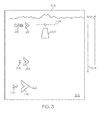
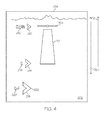
- Figures 3 , 4 and 5 illustrate these concepts in more detail.
- FIG. 3 is a simplified illustration of the 3D graphical display of FIG. 2 , in accordance with the exemplary embodiment.
- FIG. 3 is not to scale, but may be relied upon to understand the relative size and locational relationships of the objects.
- the flight path marker 204 is aligned with the "clean" chevron, symbol 210 .
- Aircraft travel is in the direction of arrow 302 .
- the terrain appears to move in the direction of arrow 304 .
- FIG. 4 is a simplified illustration of the 3D graphical display of FIG. 3 after some time has elapsed, in accordance with the exemplary embodiment.
- Flight path marker 204 is aligned with the "clean" chevron, symbol 210 .
- the aircraft has flown closer to runway 201, resulting in runway 201 appearing larger.
- FIG. 5 is a simplified illustration of the 3D graphical display of FIG. 4 after more time has elapsed, in accordance with the exemplary embodiment.
- the pilot alters the lift-to-drag ratio by, for example, deploying the gear and flaps, and lands.
- the pilot lowers the flight path marker 204 from its initial position 502 to align it with the "G+F" chevron, symbol 218, thereby moving flight path marker 204 through position 504, position 506, and position 508 before bringing it to rest in alignment with the "G+ F" symbol 218 .
- FIG. 6 is a flow chart that illustrates an exemplary embodiment of a process 600 for displaying predictive conformal configuration cues. While STEP 602-STEP 608 are arbitrarily shown as occurring in a sequence, in practice, these steps may be rearranged, customized, or have additional steps added. In addition, user input that customizes symbol shapes, symbol colors, text for aircraft configurations, techniques for displaying the objects in a visually distinguishable manner, and the like, may be accepted at any step in process 600 .
- the aircraft does not have landing gear extended and does not have flaps deployed; therefore, when process 600 starts, the "current" aircraft configuration and associated lift-to-drag ratio is generally referred to as the configuration that would lead to a "best” or “clean” landing site. The details are described in more detail hereinbelow.
- avionics data (such as geographic position data, current real-time heading data, airport feature data, aircraft body mass acceleration data, configuration data, terrain data, and the like) is received by process 600 .
- Avionics data also includes related data from aircraft subsystems such as wireless transceiver 108, navigation system 110, terrain data, and the various sensors and broadcast data.
- configuration data and/or models i.e., data corresponding to landing equipment that affects L/D, such as aircraft landing gear data, aircraft flap data, and aircraft maneuver data
- Configuration data and/or models may be uploaded once or may be altered in the course of process 600, according to user input data received at user input device 101 .
- processor 102 has the required data, and process 600 processes the data to determine a predicted landing site for various alterations of the lift-to-drag ratio that may be predetermined aircraft configurations.
- process 600 predicts landing sites for three predetermined configurations: 1) a best or "clean" glide (first) landing site, 2) a second landing site that would result from a first alternate aircraft configuration (with a first alteration in L/D), and 3) a third landing site that would result from a second alternate aircraft configuration (with a second alteration in L/D).
- the first alternate aircraft configuration may be deploying only the landing gear
- the second alternate aircraft configuration may be deploying the landing gear and the flaps.
- the predicted landings sites are indicated using optionally selectable cue symbols (see, FIG. 2- FIG. 5 , symbol 210, symbol 214 and symbol 218 ) that are displayed in perspective form on the landscape 202 . Any user selected visual distinguishability, text, and symbol selection is incorporated into the display of the conformal configuration cues in STEP 606 .
- process 600 determines whether or not the aircraft has landed. If the aircraft has not landed, process 600 continuously cycles and updates display 106 until the aircraft has landed.
- a system and method for displaying predictive cues on an aircraft display system for executing a landing after an engine failure displays the cues for various aircraft configurations, and each cue is displayed in perspective (conformally) on a three dimensional graphical display of the surrounding terrain.
Landscapes
- Engineering & Computer Science (AREA)
- Aviation & Aerospace Engineering (AREA)
- Physics & Mathematics (AREA)
- General Physics & Mathematics (AREA)
- Traffic Control Systems (AREA)
- Navigation (AREA)
- Business, Economics & Management (AREA)
- Emergency Management (AREA)
- Radar, Positioning & Navigation (AREA)
- Remote Sensing (AREA)
- Instructional Devices (AREA)
- Controls And Circuits For Display Device (AREA)
Applications Claiming Priority (1)
| Application Number | Priority Date | Filing Date | Title |
|---|---|---|---|
| US14/558,067 US9418561B2 (en) | 2014-12-02 | 2014-12-02 | System and method for displaying predictive conformal configuration cues for executing a landing |
Publications (1)
| Publication Number | Publication Date |
|---|---|
| EP3029653A1 true EP3029653A1 (fr) | 2016-06-08 |
Family
ID=54707584
Family Applications (1)
| Application Number | Title | Priority Date | Filing Date |
|---|---|---|---|
| EP15196390.7A Ceased EP3029653A1 (fr) | 2014-12-02 | 2015-11-25 | Système et procédé pour afficher des repères de configuration conforme prédictif pour l'exécution d'un palier |
Country Status (3)
| Country | Link |
|---|---|
| US (1) | US9418561B2 (fr) |
| EP (1) | EP3029653A1 (fr) |
| CN (1) | CN105730704B (fr) |
Families Citing this family (9)
| Publication number | Priority date | Publication date | Assignee | Title |
|---|---|---|---|---|
| JP6683444B2 (ja) * | 2015-08-06 | 2020-04-22 | 三菱航空機株式会社 | 航空機のアプローチを判定するコンピュータシステムおよび航空機 |
| US10247574B2 (en) | 2017-05-18 | 2019-04-02 | Honeywell International Inc. | Minimum maneuverable altitude determination and display system and method |
| US10796404B2 (en) * | 2017-08-01 | 2020-10-06 | Honeywell International Inc. | Aircraft systems and methods for adjusting a displayed sensor image field of view |
| CN110221881A (zh) * | 2018-03-02 | 2019-09-10 | 北京京东尚科信息技术有限公司 | 一种集群对象在界面的呈现方法和装置 |
| CN109685932A (zh) * | 2018-12-07 | 2019-04-26 | 西安飞机工业(集团)有限责任公司 | 一种飞行数据记录系统与互联网连接的控制方法 |
| US11842651B2 (en) | 2020-09-25 | 2023-12-12 | Honeywell International Inc. | System and method for providing a runway awareness system for an aircrew of an aircraft |
| EP3975158B1 (fr) * | 2020-09-25 | 2025-11-05 | Honeywell International Inc. | Système et procédé permettant de fournir un système de connaissance de la piste à l'équipage d'un aéronef |
| US12234026B2 (en) | 2022-05-18 | 2025-02-25 | Honeywell International Inc. | Aircraft flap malfunction detection and landing assist system and method |
| KR102772340B1 (ko) * | 2023-11-10 | 2025-02-26 | 경북대학교 산학협력단 | 항공 모빌리티의 정밀 착륙을 위한 영상 기반 버티포트 검출 시스템 및 착륙 가이드 방법 |
Citations (8)
| Publication number | Priority date | Publication date | Assignee | Title |
|---|---|---|---|---|
| US4825374A (en) * | 1985-12-20 | 1989-04-25 | The Boeing Company | Aircraft descent guide system and method for creating descent guidance information |
| US20020036573A1 (en) * | 2000-08-10 | 2002-03-28 | Wyatt Ivan S. | Aircraft display with potential thrust indicator |
| US20030060940A1 (en) * | 2001-06-19 | 2003-03-27 | Humbard John Jay | Flight management system and method for providing navigational reference to emergency landing locations |
| US6573841B2 (en) * | 2001-04-02 | 2003-06-03 | Chelton Flight Systems Inc. | Glide range depiction for electronic flight instrument displays |
| US20040044446A1 (en) * | 2001-08-30 | 2004-03-04 | Honeywell International, Inc. | Avionics system for determining terminal flightpath |
| FR2885439A1 (fr) * | 2005-05-09 | 2006-11-10 | Airbus France Sas | Procede et dispositif d'aide au pilotage d'un avion lors d'une phase d'approche en vue d'un atterrissage |
| US20080162092A1 (en) * | 2006-09-15 | 2008-07-03 | Thales | Method for estimating the touchdown point of the wheels of an aircraft on a landing runway and the distance to be traveled from the touchdown point to reach a controlled speed |
| US20140343765A1 (en) * | 2012-12-28 | 2014-11-20 | Sean Patrick Suiter | Flight Assistant with Automatic Configuration and Landing Site Selection |
Family Cites Families (14)
| Publication number | Priority date | Publication date | Assignee | Title |
|---|---|---|---|---|
| US6389333B1 (en) * | 1997-07-09 | 2002-05-14 | Massachusetts Institute Of Technology | Integrated flight information and control system |
| IL155328A0 (en) * | 2000-10-10 | 2004-06-01 | Sandel Avionics Inc | Method and apparatus for reducing false taws warnings and navigating landing approaches |
| US7026956B1 (en) | 2003-10-23 | 2006-04-11 | Rockwell Collins, Inc. | Method of integrating speed deviation cues in a vehicle navigation display |
| FR2897593B1 (fr) * | 2006-02-17 | 2012-09-14 | Airbus France | Procede et systeme pour predire la possibilite d'arret complet d'un aeronef sur une piste d'atterrissage. |
| FR2903801B1 (fr) * | 2006-07-12 | 2008-09-12 | Airbus France Sas | Procede et dispositif pour la prediction de la position d'arret d'un aeronef en cours d'atterrissage. |
| FR2913780B1 (fr) * | 2007-03-13 | 2014-07-18 | Airbus France | Procede et dispositif d'aide au guidage d'un aeronef |
| US7908082B2 (en) * | 2007-05-04 | 2011-03-15 | The Boeing Company | Methods and systems for displaying airport moving map information |
| ATE528705T1 (de) | 2009-02-25 | 2011-10-15 | Boeing Co | Implementierung kontinuierlicher landeanflüge für maximale vorhersagbarkeit bei flugzeugen |
| JP5550398B2 (ja) * | 2010-03-18 | 2014-07-16 | 三菱重工業株式会社 | 舵面故障・損傷検出装置 |
| US8996204B2 (en) * | 2010-06-23 | 2015-03-31 | Honeywell International Inc. | Systems and methods for adjusting target approach speed |
| CN102320382A (zh) * | 2011-07-07 | 2012-01-18 | 中国国际航空股份有限公司 | 飞机性能检测方法 |
| US8589071B2 (en) | 2011-08-15 | 2013-11-19 | Honeywell International Inc. | Aircraft vision system including a runway position indicator |
| CN103324778A (zh) * | 2013-01-05 | 2013-09-25 | 中国航空工业集团公司西安飞机设计研究所 | 一种多支点飞机地面载荷确定方法 |
| GB2510596B (en) * | 2013-02-08 | 2015-02-18 | Ge Aviat Systems Ltd | Method for predicting a trailing edge flap fault |
-
2014
- 2014-12-02 US US14/558,067 patent/US9418561B2/en active Active
-
2015
- 2015-11-25 EP EP15196390.7A patent/EP3029653A1/fr not_active Ceased
- 2015-12-01 CN CN201511035957.0A patent/CN105730704B/zh active Active
Patent Citations (8)
| Publication number | Priority date | Publication date | Assignee | Title |
|---|---|---|---|---|
| US4825374A (en) * | 1985-12-20 | 1989-04-25 | The Boeing Company | Aircraft descent guide system and method for creating descent guidance information |
| US20020036573A1 (en) * | 2000-08-10 | 2002-03-28 | Wyatt Ivan S. | Aircraft display with potential thrust indicator |
| US6573841B2 (en) * | 2001-04-02 | 2003-06-03 | Chelton Flight Systems Inc. | Glide range depiction for electronic flight instrument displays |
| US20030060940A1 (en) * | 2001-06-19 | 2003-03-27 | Humbard John Jay | Flight management system and method for providing navigational reference to emergency landing locations |
| US20040044446A1 (en) * | 2001-08-30 | 2004-03-04 | Honeywell International, Inc. | Avionics system for determining terminal flightpath |
| FR2885439A1 (fr) * | 2005-05-09 | 2006-11-10 | Airbus France Sas | Procede et dispositif d'aide au pilotage d'un avion lors d'une phase d'approche en vue d'un atterrissage |
| US20080162092A1 (en) * | 2006-09-15 | 2008-07-03 | Thales | Method for estimating the touchdown point of the wheels of an aircraft on a landing runway and the distance to be traveled from the touchdown point to reach a controlled speed |
| US20140343765A1 (en) * | 2012-12-28 | 2014-11-20 | Sean Patrick Suiter | Flight Assistant with Automatic Configuration and Landing Site Selection |
Also Published As
| Publication number | Publication date |
|---|---|
| US9418561B2 (en) | 2016-08-16 |
| CN105730704B (zh) | 2020-09-08 |
| US20160155341A1 (en) | 2016-06-02 |
| CN105730704A (zh) | 2016-07-06 |
Similar Documents
| Publication | Publication Date | Title |
|---|---|---|
| US9418561B2 (en) | System and method for displaying predictive conformal configuration cues for executing a landing | |
| EP2851889B1 (fr) | Système et procédé permettant de traiter et d'afficher des turbulences de sillage | |
| US8209122B2 (en) | System and method for rendering visible features of a target location on a synthetic flight display | |
| US8676399B2 (en) | System and method for generating and displaying an electric taxi index | |
| US7212216B2 (en) | Perspective view primary flight display with terrain-tracing lines and method | |
| US9389097B2 (en) | Aircraft display systems and methods for enhanced display of flight path information | |
| EP2837565B1 (fr) | Systèmes d'aéronef et procédés pour afficher des informations d'éclairage sur piste | |
| EP2827104A1 (fr) | Systèmes d'affichage et procédés permettant des affichages ayant une fonctionnalité de pilote automatique intégrée | |
| EP2107340A2 (fr) | Système et procédé d'affichage de point de cheminement | |
| US8810435B2 (en) | Apparatus and method for displaying a helicopter approach to an airport landing pad | |
| EP2166311B1 (fr) | Procédé et appareil pour configurer un point de cheminement | |
| US20100023264A1 (en) | Aircraft display systems and methods with obstacle warning envelopes | |
| CN105549938A (zh) | 用于显示跑道着陆信息的系统和方法 | |
| EP3079138A2 (fr) | Systèmes d'aéronef et procédés pour afficher un éclairage de piste amélioré | |
| CN105608932A (zh) | 用于显示跑道进场信息的系统和方法 | |
| US9340282B2 (en) | System and method for displaying vertical reference on a rotorcraft system | |
| EP3082121A1 (fr) | Systèmes d'aéronef et procédés pour afficher des plates-formes d'atterrissage en mouvement | |
| EP1290411B1 (fr) | Procede et appareil d'affichage d'informations de navigation en temps reel | |
| EP2759805A2 (fr) | Procédé et système d'affichage d'un point d'interception de terrain d'hélicoptère pendant l'atterrissage | |
| EP3023741B1 (fr) | Système et procédé d'affichage exocentrique de navigation intégrée | |
| EP2508847A2 (fr) | Systèmes et procédés permettant d'informer le pilote d'un aéronef à propos d'un état topographique | |
| US9501938B1 (en) | Surface information generating system, device, and method |
Legal Events
| Date | Code | Title | Description |
|---|---|---|---|
| PUAI | Public reference made under article 153(3) epc to a published international application that has entered the european phase |
Free format text: ORIGINAL CODE: 0009012 |
|
| 17P | Request for examination filed |
Effective date: 20151125 |
|
| AK | Designated contracting states |
Kind code of ref document: A1 Designated state(s): AL AT BE BG CH CY CZ DE DK EE ES FI FR GB GR HR HU IE IS IT LI LT LU LV MC MK MT NL NO PL PT RO RS SE SI SK SM TR |
|
| AX | Request for extension of the european patent |
Extension state: BA ME |
|
| STAA | Information on the status of an ep patent application or granted ep patent |
Free format text: STATUS: EXAMINATION IS IN PROGRESS |
|
| 17Q | First examination report despatched |
Effective date: 20170308 |
|
| APBK | Appeal reference recorded |
Free format text: ORIGINAL CODE: EPIDOSNREFNE |
|
| APBN | Date of receipt of notice of appeal recorded |
Free format text: ORIGINAL CODE: EPIDOSNNOA2E |
|
| RAP3 | Party data changed (applicant data changed or rights of an application transferred) |
Owner name: HONEYWELL INTERNATIONAL INC. |
|
| APBR | Date of receipt of statement of grounds of appeal recorded |
Free format text: ORIGINAL CODE: EPIDOSNNOA3E |
|
| APAF | Appeal reference modified |
Free format text: ORIGINAL CODE: EPIDOSCREFNE |
|
| P01 | Opt-out of the competence of the unified patent court (upc) registered |
Effective date: 20230421 |
|
| APBT | Appeal procedure closed |
Free format text: ORIGINAL CODE: EPIDOSNNOA9E |
|
| STAA | Information on the status of an ep patent application or granted ep patent |
Free format text: STATUS: THE APPLICATION HAS BEEN REFUSED |
|
| 18R | Application refused |
Effective date: 20240426 |