EP3029657B1 - Mehrsichtanzeigesystem - Google Patents
Mehrsichtanzeigesystem Download PDFInfo
- Publication number
- EP3029657B1 EP3029657B1 EP15183807.5A EP15183807A EP3029657B1 EP 3029657 B1 EP3029657 B1 EP 3029657B1 EP 15183807 A EP15183807 A EP 15183807A EP 3029657 B1 EP3029657 B1 EP 3029657B1
- Authority
- EP
- European Patent Office
- Prior art keywords
- coupling
- displays
- adjacent
- display
- coupled
- Prior art date
- Legal status (The legal status is an assumption and is not a legal conclusion. Google has not performed a legal analysis and makes no representation as to the accuracy of the status listed.)
- Active
Links
Images


Classifications
-
- H—ELECTRICITY
- H05—ELECTRIC TECHNIQUES NOT OTHERWISE PROVIDED FOR
- H05K—PRINTED CIRCUITS; CASINGS OR CONSTRUCTIONAL DETAILS OF ELECTRIC APPARATUS; MANUFACTURE OF ASSEMBLAGES OF ELECTRICAL COMPONENTS
- H05K7/00—Constructional details common to different types of electric apparatus
- H05K7/18—Construction of rack or frame
-
- G—PHYSICS
- G06—COMPUTING OR CALCULATING; COUNTING
- G06F—ELECTRIC DIGITAL DATA PROCESSING
- G06F3/00—Input arrangements for transferring data to be processed into a form capable of being handled by the computer; Output arrangements for transferring data from processing unit to output unit, e.g. interface arrangements
- G06F3/14—Digital output to display device ; Cooperation and interconnection of the display device with other functional units
- G06F3/1423—Digital output to display device ; Cooperation and interconnection of the display device with other functional units controlling a plurality of local displays, e.g. CRT and flat panel display
- G06F3/1446—Digital output to display device ; Cooperation and interconnection of the display device with other functional units controlling a plurality of local displays, e.g. CRT and flat panel display display composed of modules, e.g. video walls
-
- F—MECHANICAL ENGINEERING; LIGHTING; HEATING; WEAPONS; BLASTING
- F16—ENGINEERING ELEMENTS AND UNITS; GENERAL MEASURES FOR PRODUCING AND MAINTAINING EFFECTIVE FUNCTIONING OF MACHINES OR INSTALLATIONS; THERMAL INSULATION IN GENERAL
- F16M—FRAMES, CASINGS OR BEDS OF ENGINES, MACHINES OR APPARATUS, NOT SPECIFIC TO ENGINES, MACHINES OR APPARATUS PROVIDED FOR ELSEWHERE; STANDS; SUPPORTS
- F16M11/00—Stands or trestles as supports for apparatus or articles placed thereon ; Stands for scientific apparatus such as gravitational force meters
- F16M11/02—Heads
- F16M11/04—Means for attachment of apparatus; Means allowing adjustment of the apparatus relatively to the stand
- F16M11/043—Allowing translations
-
- G—PHYSICS
- G09—EDUCATION; CRYPTOGRAPHY; DISPLAY; ADVERTISING; SEALS
- G09F—DISPLAYING; ADVERTISING; SIGNS; LABELS OR NAME-PLATES; SEALS
- G09F9/00—Indicating arrangements for variable information in which the information is built-up on a support by selection or combination of individual elements
- G09F9/30—Indicating arrangements for variable information in which the information is built-up on a support by selection or combination of individual elements in which the desired character or characters are formed by combining individual elements
- G09F9/302—Indicating arrangements for variable information in which the information is built-up on a support by selection or combination of individual elements in which the desired character or characters are formed by combining individual elements characterised by the form or geometrical disposition of the individual elements
- G09F9/3026—Video wall, i.e. stackable semiconductor matrix display modules
-
- H—ELECTRICITY
- H04—ELECTRIC COMMUNICATION TECHNIQUE
- H04N—PICTORIAL COMMUNICATION, e.g. TELEVISION
- H04N5/00—Details of television systems
- H04N5/64—Constructional details of receivers, e.g. cabinets or dust covers
- H04N5/655—Construction or mounting of chassis, e.g. for varying the elevation of the tube
-
- G—PHYSICS
- G09—EDUCATION; CRYPTOGRAPHY; DISPLAY; ADVERTISING; SEALS
- G09G—ARRANGEMENTS OR CIRCUITS FOR CONTROL OF INDICATING DEVICES USING STATIC MEANS TO PRESENT VARIABLE INFORMATION
- G09G2300/00—Aspects of the constitution of display devices
- G09G2300/02—Composition of display devices
- G09G2300/026—Video wall, i.e. juxtaposition of a plurality of screens to create a display screen of bigger dimensions
-
- H—ELECTRICITY
- H10—SEMICONDUCTOR DEVICES; ELECTRIC SOLID-STATE DEVICES NOT OTHERWISE PROVIDED FOR
- H10K—ORGANIC ELECTRIC SOLID-STATE DEVICES
- H10K59/00—Integrated devices, or assemblies of multiple devices, comprising at least one organic light-emitting element covered by group H10K50/00
- H10K59/10—OLED displays
- H10K59/18—Tiled displays
Definitions
- Apparatuses and methods consistent with exemplary embodiments relate to a multivision display system including a plurality of displays.
- Multivision display systems are systems for providing one screen using a plurality of displays.
- multivision display systems each include a plurality of displays installed vertically and horizontally adjacent to each other and allow each of the plurality of displays to display a part of the whole screen to be displayed.
- US 2008/0263924 A1 describes a transportable electronic sign display system.
- EP 1995508 A2 describes a flat display having main body for receiving a display panel.
- WO 2011/113145 A1 describes a system of linkable electronic display devices.
- CN103982755 discloses a multivision display having an adjusting device to adjust the height of adjacent display by a part rotating eccentrically inside one of the frame members.
- Multivision display systems may be formed by fixedly installing displays on the wall using wall mounts fixed to the wall or may be formed by stands which support the plurality of displays.
- aspects of one or more exemplary embodiments also provide a multivision display system in which it is possible to easily dispose vertical, horizontal, front, and rear positions of displays disposed vertically and horizontally adjacent to each other.
- a multivision display system including: a plurality of displays; and at least one stand configured to support the plurality of displays wherein the stand includes: a base; and a plurality of coupling frames configured to support the plurality of displays and which are mutually coupled to each other.
- the plurality of coupling frames each include: a coupling portion extending from one end thereof; and a coupling groove provided on the other end thereof and coupled with a coupling portion of an adjacent coupling frame.
- the system includes a position adjuster configured to adjust a level difference between the plurality of displays which are disposed vertically or horizontally adjacent to each other.
- the position adjuster is configured to adjust a position of the coupling portion coupled inside the coupling groove.
- the coupling groove has a larger width than the coupling portion of the adjacent coupling frame coupled with the coupling groove in such a way that the coupling portion of the adjacent coupling frame coupled with the coupling groove is movable left and right in the horizontal direction in the coupling groove; and the position adjuster includes a left and right adjusting screw in the coupling frame and configured to move the coupling portion coupled inside the coupling groove left and right in the horizontal direction.
- the position adjuster further includes: an elevating guide configured to move inside the coupling groove, and a top and bottom adjusting screw in the coupling frame and configured to move the elevating guide left and right; and a bottom surface of the coupling portion and a top surface of the elevating guide may be formed with corresponding inclined surfaces.
- the system may further include a first roller rotatably provided on the bottom surface of the coupling portion and a second roller rotatably provided on a bottom of the elevating guide.
- the system may further include: a pair of clamps on two adjacent coupling frames, among the plurality of coupling frames, that are on two adjacent displays, among the plurality of displays; and a coupling member configured to fix the pair of clamps to each other.
- the system may further include a spacer disposed between side surfaces of two adjacent displays, among the plurality of displays, to block a gap formed between outer surfaces of the two adjacent displays.
- the plurality of displays may each include an accommodating groove provided concavely on a side surface thereof and configured to accommodate at least a part of the spacer.
- the spacer may include an elastic-deformable material and may be thicker than a depth of the accommodating groove.
- the plurality of coupling frames may each have a bar shape and may be respectively coupled with a rear surface of each of the plurality of displays.
- the plurality of coupling frames may respectively be on both sides of the plurality of displays.
- a multivision display system including: a plurality of displays; and a plurality of wall mounts configured to support the plurality of displays, while installed on a wall, and to support horizontal movement of the plurality of displays.
- Each of the plurality of wall mounts may include a guide rail extending horizontally; and each of the plurality of displays may include a pair of engaging members fixed to a rear surface of the corresponding display and movably engaged in the guide rail.
- Each of the pair of engaging members may include an engaging portion engaged in the guide rail; and each of the plurality of wall mounts may include a rotatable elevating screw, a bottom of which passes through the engaging portion and is supported by the guide rail.
- the system may further include a cap installed on the bottom of the rotatable elevating screw.
- the guide rail may be configured to be movable forward and backward relative to the wall.
- Each of the plurality of wall mounts may include: a pair of forward and backward adjusting screws provided on both sides of the guide rail; and a forward and backward adjusting nut configured to rotate while being coupled with the forward and backward adjusting screws and to move the forward and backward adjusting screws forward and backward.
- Each of the plurality of wall mounts may include: a fixed bracket configured to be fixed to the wall; a mobile bracket comprising the guide rail and installed on the fixed bracket to be movable forward and backward relative to the wall; and a link assembly which connects the fixed bracket with the mobile bracket and movably supports the mobile bracket.
- the system may further include a locking device configured to allow the mobile bracket to be fixed to the fixed bracket.
- the locking device may include: a locking member installed on the fixed bracket to be movable vertically, and an elastic member elastically supporting the locking member upward; and wherein the mobile bracket comprises a locking portion configured to lock the locking member.
- a stand for a multivision display system including: a base configured to be supported by a horizontal surface; and a plurality of coupling frames configured to support a plurality of displays and which are mutually coupled to each other to adjust relative positions of the plurality of displays.
- the plurality of coupling frames may each have a bar shape and may be configured to be respectively coupled with a rear surface of each of the plurality of displays.
- the plurality of coupling frames each include: a coupling portion extending from one end of the coupling frame; and a coupling groove provided on another end of the coupling frame and coupled with a coupling portion of an adjacent coupling frame.
- the stand further includes a position adjuster configured to adjust a position of the coupling portion coupled inside the coupling groove.
- the coupling groove has a larger width than the coupling portion to allow the coupling portion of the adjacent coupling frame inserted into the coupling groove to move left and right inside the coupling groove; and the position adjuster includes a left and right adjusting screw in the coupling frame and configured to move the coupling portion coupled inside the coupling groove left and right.
- the position adjuster further includes: an elevating guide configured to move inside the coupling groove, and a top and bottom adjusting screw in the coupling frame and configured to move the elevating guide left and right; and a bottom surface of the coupling portion and a top surface of the elevating guide may be formed with corresponding inclined surfaces.
- the stand may further include a first roller rotatably provided on the bottom surface of the coupling portion and a second roller rotatably provided on a bottom of the elevating guide.
- the stand may further include: a pair of clamps on two adjacent coupling frames, among the plurality of coupling frames; and a coupling member configured to fix the pair of clamps to each other.
- a multivision display system 10 includes the plurality of displays 110 and a stand 120 that allows or supports the plurality of displays 110 to stand on a horizontal surface.
- Each of the plurality of displays 110 includes a display module 111 (e.g., display panel) on which images are displayed and a case 112 that contains the display module 111.
- a display module 111 e.g., display panel
- case 112 that contains the display module 111.
- the stand 120 includes a base 121 supported by the horizontal surface, as shown in FIGS. 2 and 3 , a plurality of coupling frames 122 fixed to a rear surface of the display 110 and mutually coupled to each other in a vertical direction, and a dummy module 123 installed between the base 121 and the display 110 to allow the display 110 to be installed at a certain height.
- the base 121 is formed in an approximate hexagonal shape, which the dummy module 123 is installed on. Casters may be rotatably installed below the base 121 for moving the multivision display system.
- the coupling frames 122 each have a bar shape that extends up and down to be long.
- Two coupling frames 122 are installed on both sides of the rear surface of the display 110 to individually control the heights of both sides of the display 110. Accordingly, the heights of both sides of the display 110 are controlled using the two coupling frames 122, thereby adjusting a level of the display 110.
- the coupling frames 122 are installed on both sides of the rear surface of the display 110.
- the coupling frames 122 may be installed on both sides of the display 110.
- the coupling frames 122 each include a coupling portion 122a that protrudes from a bottom end of the coupling frame 122 and is coupled with the coupling frame 122 located adjacent to the bottom end, and a coupling groove 122b provided on a top end of the coupling frame 122 and into which the coupling portion 122a of the coupling frame 122 located adjacent to a top thereof is inserted.
- the coupling portion 122a protrudes from the bottom end of the coupling frame 122 and the coupling groove 122b is provided on the top end of the coupling frame 122.
- a coupling portion 122a may extend from a top end of a coupling frame 122 and a coupling groove 122b may be provided on a bottom end of the coupling frame 122.
- the dummy module 123 allows the plurality of displays 110 to be installed (e.g., provided) while being separate from the horizontal surface by a certain distance, thereby providing a screen of the multivision display system 10 at the certain distance.
- the coupling frames 122 are installed on both sides of a rear surface of the dummy module 123, respectively.
- the dummy module 123 may include various substrates which control an operation of the multivision display system 10.
- the plurality of displays 110 are installed vertically on the stand 120 using the coupling frames 122 and a plurality of stands 120 on which the plurality of displays 110 are installed, respectively, are disposed horizontally adjacent to each other, thereby disposing the plurality of displays 110 vertically and horizontally adjacent to each other.
- four displays 110 are installed on each of two stands 120 that are disposed horizontally adjacent to each other, thereby forming the multivision display system 10 using a total of eight displays 110.
- the plurality of displays 110 installed with the coupling frames 122 on the rear surface may be sequentially stacked on one of the base 121 and the dummy module 123, thereby easily constructing the multivision display system 10 in which the plurality of displays 110 are disposed vertically.
- the plurality of stands 120 on which the plurality of displays 110 are disposed vertically are disposed left and right, thereby easily constructing the multivision display system 10 in which the plurality of displays 110 are disposed left and right.
- the displays 110 disposed vertically and horizontally may be slightly misaligned from one another due to a tolerance, which causes a phenomenon in which locations of parts of images are misaligned on the entire screen.
- the multivision display system 10 includes a position adjuster for adjusting the level difference between the adjacent displays 110 which are disposed vertically or horizontally adjacent to each other.
- the position adjuster may adjust the level difference between the displays 110 disposed adjacent to each other by adjusting a position of the coupling portion 122a of the adjacent coupling frame 122 coupled with the coupling groove 122b.
- the coupling groove 122b is formed (e.g., provided) to have a relatively greater width than the coupling portion 122a in such a way that the coupling portion 122a of the adjacent coupling frame 122 coupled with the coupling groove 122b is movable left and right in the coupling groove 122b.
- the position adjuster includes a left and right adjusting screw 124 (e.g., horizontal adjusting screw) that is coupled with a top of the coupling frame 122 in such a way that a front end thereof protrudes into the coupling groove 122b and supports the coupling portion 122a coupled with the coupling groove 122b to move the coupling portion 122a left and right.
- a left and right adjusting screw 124 e.g., horizontal adjusting screw
- the left and right adjusting screw 124 is rotated forward and backward in such a way that the coupling portion 122a moves left and right due to the left and right adjusting screw 124. Accordingly, the display 110 located above the left and right adjusting screw 124 moves left and right, thereby aligning left and right positions of the two displays 110 disposed vertically.
- the position adjuster includes an elevating guide 125 disposed inside the coupling groove 122b to allow the coupling portion 122a to move vertically, thereby moving the displays 110.
- the elevating guide 125 is installed inside the coupling groove 122b to be movable left and right, and a top surface thereof is formed to be inclined. Also, the coupling portion 122a is formed to allow a bottom surface thereof to be inclined to correspond to the top surface of the elevating guide 125.
- the position adjuster includes a top and bottom adjusting screw 126 that is coupled with the top of the coupling frame 122 in such a way that a front end thereof protrudes into the coupling groove 122b and moves the elevating guide 125 disposed inside the coupling groove 122b.
- the elevating guide 125 is moved left and right by rotating the top and bottom adjusting screw 126 forward and backward in such a way that the coupling portion 122a of the coupling frame 122 moves up and down as the elevating guide 125 moves, thereby moving the display 110 installed with the coupling frame 122 up and down.
- the coupling frames 122 are installed on both sides of the rear of the display 110, respectively, the heights of the both sides of the display 110 may be adjusted, respectively.
- rollers 125a and 122c are rotatably installed on a bottom of the elevating guide 125 and a bottom of the coupling portion 122a, respectively, in such a way that the movement of the elevating guide 125 and the movement of the coupling frame 122 are performed smoothly.
- a clamp 127 is installed on the coupling frame 122.
- the clamp 127 is installed on each of the two coupling frames 122 installed adjacent to each other, on the rear surfaces of the adjacent displays 110.
- the clamps 127 are formed in an L shape, are fixed to the two adjacent coupling frames 122, respectively, and are mutually fixed using coupling members S such as screws.
- front and rear positions of the two clamps 127 coupled with each other are adjusted to adjust mutual positions of the two adjacent displays 110 and then the two clamps 127 are fixed using the members S, thereby allowing the front and rear positions of the two displays 110 to be aligned.
- one fixing plate 128 is fixed to tops of the two coupling frames 122 located uppermost among the coupling frames 122 using the coupling members S to mutually fix the tops of the two coupling frames 122.
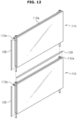
- spacers 129 are disposed to prevent gaps that may occur inevitably due to tolerances among four side surfaces, provided vertically and horizontally, of the two displays 110 mutually adjacent to each other.
- the spacers 129 are formed to have an approximate rectangular cross section while extending to correspond to the side surfaces of the display 110. Also, the spacers 129 are formed of an elastic-deformable material and the four side surfaces, provided vertically and horizontally on the case 112, of the display 110 are concave and provide accommodating grooves 112a that contain a part of the spacer 129, respectively.
- the accommodating grooves 112a are provided in central portions of the four top, bottom, left, and right surfaces of the display 110 and the spacers 129 are formed to have a relatively greater thickness than a depth of the accommodating groove 112a. Accordingly, when the spacer 129 is installed in the accommodating groove 112a of the display 110, one part of the spacer 129 is accommodated in the accommodating groove 112a and the other part of the spacer 129 protrudes from the outside of the accommodating groove 112a to be accommodated in the accommodating groove 112a provided in the adjacent display 110. Accordingly, as shown in FIGS.
- the accommodating groove 112a is provided in the central portions of the side surfaces of the displays 110.
- an accommodating groove 112a' may be formed with a step on a rear end of the side surface of the display 110.
- a spacer 129' is formed to have an approximate rectangular cross section, in which a concavo-convex shape is formed on one side of the spacer 129' to allow the spacer 129' to be more easily elastic-deformable while the displays 110 are being installed on the stand 120.
- a spacer 129" is formed to have a T-shaped cross section in such a way that portions extending vertically may be supported by the rear surfaces of the two displays 110 and a horizontally protruding portion may be inserted between the side surfaces of the displays 110.
- the horizontally protruding portion of the spacer 129" may be inserted between the side surfaces of the two displays 110 or may be attached to the side surface of the display 110. In this case, it is unnecessary to form accommodating grooves in the displays 110 as in the previously-described exemplary embodiments.
- the stands 120 each include (or are connected to) one dummy module 123, though it is understood that one or more other exemplary embodiments are not limited thereto.
- each of the stands 120 may include (or be connected to) a plurality of dummy modules 123.
- the stand 120 may not have a configuration corresponding to the dummy module 123 and the coupling frames 122 may be directly installed on the base 121.
- the multivision display system 10 is formed with the two stands 120 on each of which the four displays 110 are installed, respectively.
- the two stands 120 on each of which the four displays 110 are installed, respectively.
- one or more other exemplary embodiments are not limited thereto.
- various numbers of displays 110 and stands 120 may be used to form the multivision display system 10.
- the two coupling frames 122 are coupled with both sides of the rear surface of the display 110, respectively.
- the coupling frames 122 may be installed on both side surfaces of the display 110.
- the two coupling frames 122 are installed on the display 110 to adjust the level of the display 110.
- one or more other exemplary embodiments are not limited thereto.
- only one coupling frame 122 may be installed with each display 110 while the display 110 is rotatably coupled with the coupling frame 122 to adjust the level of the displays 110 by rotating the display 110.
- top and bottom positions of the displays 110 are adjusted using the coupling frames, thereby mutually aligning heights of the displays disposed horizontally.
- the coupling frame 122 is separately provided from the display 110 and installed on the display 110.
- a coupling portion 122a and a coupling groove 122b may be formed in a case forming an exterior of a display 110 and a position adjuster may be installed therein.
- the coupling frame 122 is coupled with the rear surface of the display 110, that is, the outer side thereof.
- the coupling frame 122 may be coupled while being accommodated in a case forming an exterior of the display 110.
- the coupling frame 122 is formed to have a bar shape extending up and down.
- the coupling frame 122 may be formed to have a bar extending horizontally or may be formed to have various shapes other than the bar shape depending on a design.
- the multivision display system 20 includes a plurality of displays 210 disposed vertically and horizontally to each other and a plurality of wall mounts 220 that are fixed to the wall vertically and horizontally to each other and support the displays 210, respectively.
- the multivision display system 20 includes a total of six displays 210 that are disposed vertically in three rows and horizontally in two columns and includes a total of six wall mounts 220 installed on the wall vertically in three rows and horizontally in two columns to correspond to the displays 210.
- the wall mounts 220 include a fixed bracket 221 fixed to the wall, a mobile bracket 222 installed to be movable forward and backward with respect to the fixed bracket 221, and a link assembly 223 that allows the mobile bracket 222 to be movably installed on the fixed bracket 221.
- the display 210 is installed on the mobile bracket 222. Accordingly, the display 210 is installed on the wall using the wall mount 220 to be movable forward and backward.
- the display 210 is installed on the wall mount 220 to be movable horizontally.
- a guide rail 222a which extends long left and right is provided on the mobile bracket 222 of the wall mount 220.
- An engaging member 211 is installed on the rear surface of the display 210 to allow the display 210 to be attached and installed in the guide rail 222a.
- Two engaging members 211 are installed on both sides of the rear surface of the display 210, and each of the engaging members 211 includes an engaging portion 211a that fits in a top end of the guide rail 222a.
- the two guide rails 222a are disposed in a top and bottom of the mobile bracket 222 with a gap.
- the engaging portions 211a that fit on the two guide rails 222a respectively are provided at a top and bottom of each of the engaging members 211.
- the engaging member 211 may move horizontally along the guide rail 222a while fitting on the guide rail 222a using the engaging portion 211a.
- a user may move the displays 210 by applying a force to the left and right of the displays 210 to align the left and right positions of the displays 210 disposed vertically.
- the engaging portion 211a includes an elevating screw 212 that is rotatably installed on the engaging portions 211a and includes a bottom end passing through the engaging portion 211a and supported by the guide rail 222a.
- a cap 212a formed of rubber covers the bottom end of the elevating screw 212, and the bottom end of the elevating screw 212 is allowed to be supported by the guide rail 222a via the cap 212a.
- the elevating screw 212 moves vertically, thereby moving the display 210 vertically. Therefore, the user may align top and bottom positions of the displays 210 disposed horizontally adjacent to each other while rotating the elevating screw 212.
- the guide rail 222a is installed on the mobile bracket 222 to be movable forward and backward to adjust a position of the display 210 forward and backward.
- a forward and backward adjusting screw 222b is installed on each of both sides of the guide rail 222a and a forward and backward adjusting nut 222c rotatably installed in the mobile bracket 222 and screw-coupled with the forward and backward adjusting screw 222b is disposed in the mobile bracket 222.
- the forward and backward adjusting screw 222b moves forward and backward and the guide rail 222a moves forward and backward together with the forward and backward adjusting screw 222b. Since the display 210 is installed while being attached in the guide rail 222a using the engaging member 211, the display 210 moves forward and backward together with the guide rail 222a.
- the user may mutually align front and rear positions of the displays 210 disposed vertically to each other by rotating the forward and backward adjusting nut 222c forward and backward.
- the link assembly 223, as shown in FIG. 21 includes a first link 223a with one end rotatably installed on the fixed bracket 221 and another end installed on the mobile bracket 222 to be rotatable and movable vertically, and a second link 223b with one end rotatably installed on the mobile bracket 222 and another end installed on the fixed bracket 221 to be rotatable and movable vertically.
- the first link 223a and the second link 223b are installed to allow central portions thereof to be rotatable.
- the displays 210 move horizontally using the guide rail 222a, move vertically using the elevating screw 212, and move forward and backward using the forward and backward adjusting screw 222b and the forward and backward adjusting nut 222c, relative positions of the displays 210 may be adjusted to be precisely aligned.
- the wall mount 220 includes a locking device 224 for restricting the movement of the mobile bracket 222.
- the locking device 224 includes a locking member 224a installed in guide slots 221a provided on the fixed bracket 221 to be movable vertically, an elastic member 224b that elastically supports the locking member 224a upward, and a locking portion 222d that is provided on the mobile bracket 222 and fits on the locking member 224a to lock the locking member 224a.
- locking devices 224 are provided on upper portions and lower portions of both sides of the wall mount 220, respectively.
- the wall mount 220 to easily install the display 210, includes the fixed bracket 221, the mobile bracket 222, and the link assembly 223 to move the display 210 forward and backward.
- the wall mount 220 may include only the fixed bracket 221, and the guide rail 222a may be installed on the fixed bracket 221.
- displays may be installed vertically adjacent by coupling frames installed on rear surfaces of displays with one another and may be disposed horizontally adjacent by disposing stands horizontally, on which the displays are installed, thereby easily installing a multivision display system.
- displays may be moved vertically, horizontally, and forward and backward, top, bottom, left, right, front, and rear positions of the displays may be easily aligned with one another.
Landscapes
- Engineering & Computer Science (AREA)
- Theoretical Computer Science (AREA)
- Multimedia (AREA)
- Physics & Mathematics (AREA)
- General Physics & Mathematics (AREA)
- General Engineering & Computer Science (AREA)
- Human Computer Interaction (AREA)
- Devices For Indicating Variable Information By Combining Individual Elements (AREA)
- Microelectronics & Electronic Packaging (AREA)
- Mechanical Engineering (AREA)
- Signal Processing (AREA)
- Transforming Electric Information Into Light Information (AREA)
Claims (8)
- Ein Multivisionsdisplaysystem (10), das Folgendes umfasst:eine Vielzahl von Displays (110, 210); undmindestens einen Ständer (120), der so konfiguriert ist, dass er die Mehrzahl von Displays (110, 210) trägt, um jedes Display der Mehrzahl von Displays (110, 210) neben einem anderen Display der Mehrzahl von Displays (110, 210) in vertikaler und/oder horizontaler Richtung zu installieren,wobei der Ständer (120) Folgendes umfasst:eine Basis (121);eine Mehrzahl von Kopplungsrahmen (122), die sich in der vertikalen Richtung erstrecken
die so konfiguriert sind, dass sie die Vielzahl von Displays (110, 210) tragen und die miteinander gekoppelt sind; undeine Positionseinstelleinrichtung, die so konfiguriert ist, dass sie einen Höhenunterschied zwischen der Vielzahl von Displays (110, 210) einstellt, die vertikal oder horizontal nebeneinander angeordnet sind;dadurch gekennzeichnet, dassdie Vielzahl von Kopplungsrahmen (122) jeweils Folgendes umfasst:einen Kopplungsabschnitt (122a), der sich von einem Ende davon erstreckt; undeine Kupplungsnut (122b), die an ihrem anderen Ende vorgesehen und mit dem Kupplungsabschnitt (122a) eines benachbarten Kupplungsrahmens (122) verbunden ist und die so ausgebildet ist, dass sie eine größere Breite als der mit der Kupplungsnut (122b) gekoppelte Kupplungsabschnitt (122a) des benachbarten Kupplungsrahmens (122) aufweist, so dass der mit der Kupplungsnut (122b) gekoppelte Kupplungsabschnitt (122a) des benachbarten Kupplungsrahmens (122) in der horizontalen Richtung in der Kupplungsnut (122b) nach links und rechts bewegbar ist; die Positionseinstellvorrichtung umfasst eine linke und rechte Einstellschraube (124) zum Einstellen von horizontalen Differenzen,
die in dem Kupplungsrahmen (122) installiert ist und so konfiguriert ist, dass sie den innerhalb der Kupplungsnut (122b) gekoppelten Kupplungsabschnitt (122a) nach links und rechts in der horizontalen Richtung bewegt;eine Hubführung (125), die so installiert ist, dass sie sich innerhalb der Kupplungsnut (122b) bewegt; undeine obere und untere Einstellschraube (126) zum Einstellen vertikaler Differenzen,
die in dem Kupplungsrahmen (122) installiert und so konfiguriert ist, dass sie die Hubführung (125) nach links und rechts in der horizontalen Richtung bewegt, und wobei eine untere Fläche des Kupplungsabschnitts und eine obere Fläche der Hubführung (125) mit entsprechenden schrägen Flächen ausgebildet sind. - System nach Anspruch 1, wobei die mehreren Kupplungsrahmen (122) jeweils eine Stabform aufweisen und jeweils mit einer hinteren Fläche jedes der mehreren Displays (110, 210) gekoppelt sind.
- System nach Anspruch 2, wobei die mehreren Kupplungsrahmen (122) jeweils auf beiden Seiten der mehreren Displays (110, 210) installiert sind.
- System nach Anspruch 1, das ferner Rollen (122c, 125a) umfasst, die drehbar an einer Unterseite des Kupplungsabschnitts (122a) bzw. an einer Unterseite der Hubführung (125) installiert sind.
- Das System nach Anspruch 1 umfasst ferner Folgendes:ein Paar Klemmen (127), die an den beiden Kupplungsrahmen installiert sind, die nebeneinander an zwei nebeneinander angeordneten Displays (110, 210) installiert sind; undein Kupplungselement (S), das so konfiguriert ist, dass es das Paar von Klammern aneinander befestigt.
- System nach Anspruch 1, das ferner einen Abstandshalter (129, 129', 129") umfasst, der zwischen den Seitenflächen von zwei benachbarten Displays (110) angeordnet ist, um einen zwischen den Außenflächen der beiden benachbarten Displays (110, 210) gebildeten Spalt zu blockieren.
- System nach Anspruch 6, wobei die mehreren Displays (110, 210) jeweils eine Aufnahmenut (112a) aufweisen, die konkav an einer ihrer Seitenflächen vorgesehen ist und einen Teil des Abstandshalters (129, 129', 129") aufnimmt.
- System nach Anspruch 6, wobei der Abstandshalter (129, 129', 129") aus einem elastisch verformbaren Material gebildet und so geformt ist, dass er dicker als eine Tiefe der Aufnahmenut (112a) ist.
Applications Claiming Priority (1)
| Application Number | Priority Date | Filing Date | Title |
|---|---|---|---|
| KR1020140169541A KR102189234B1 (ko) | 2014-12-01 | 2014-12-01 | 멀티 비전 |
Publications (2)
| Publication Number | Publication Date |
|---|---|
| EP3029657A1 EP3029657A1 (de) | 2016-06-08 |
| EP3029657B1 true EP3029657B1 (de) | 2023-11-01 |
Family
ID=54105625
Family Applications (1)
| Application Number | Title | Priority Date | Filing Date |
|---|---|---|---|
| EP15183807.5A Active EP3029657B1 (de) | 2014-12-01 | 2015-09-04 | Mehrsichtanzeigesystem |
Country Status (3)
| Country | Link |
|---|---|
| US (1) | US9854701B2 (de) |
| EP (1) | EP3029657B1 (de) |
| KR (1) | KR102189234B1 (de) |
Families Citing this family (30)
| Publication number | Priority date | Publication date | Assignee | Title |
|---|---|---|---|---|
| KR102270484B1 (ko) | 2015-06-24 | 2021-06-29 | 삼성전자주식회사 | 디스플레이 모듈, 디스플레이 장치 및 디스플레이 모듈의 조립 또는 해체 방법 |
| EP3378055A1 (de) * | 2015-12-31 | 2018-09-26 | Vstream Digital Media, Ltd | Anzeigeanordnung mit internem anzeigebildschirmturm, der von externen anzeigebildschirmseiten umgeben ist |
| KR102519930B1 (ko) * | 2016-07-07 | 2023-04-11 | 삼성전자주식회사 | 디스플레이 장치 |
| CN105972393A (zh) * | 2016-07-18 | 2016-09-28 | 合肥盈川信息技术有限公司 | 一种拼接屏支架 |
| KR102009663B1 (ko) | 2016-07-26 | 2019-10-21 | 삼성전자주식회사 | 디스플레이 장치의 결합 구조 및 디스플레이 장치 |
| US10531581B2 (en) * | 2016-10-28 | 2020-01-07 | Lg Electronics Inc. | Display apparatus |
| CN108335629B (zh) * | 2017-01-20 | 2025-07-11 | 中兴通讯股份有限公司 | 一种显示终端 |
| KR102389729B1 (ko) * | 2017-05-22 | 2022-04-22 | 엘지전자 주식회사 | 반도체 발광 소자를 이용한 디스플레이 장치 |
| JP6758492B2 (ja) * | 2017-05-22 | 2020-09-23 | 三菱電機株式会社 | 表示モジュール群、表示装置、及び表示装置の製造方法 |
| KR101893692B1 (ko) * | 2017-06-02 | 2018-08-30 | 김성훈 | 3차원 촬상시스템 |
| DE102017210938A1 (de) | 2017-06-28 | 2019-01-03 | Volkswagen Aktiengesellschaft | Anzeigevorrichtung für ein Kraftfahrzeug, Verfahren zur Herstellung einer Anzeigevorrichtung für ein Kraftfahrzeug |
| KR102541526B1 (ko) * | 2018-07-27 | 2023-06-09 | 삼성전자주식회사 | 디스플레이 장치 및 그 제조방법 |
| KR102226009B1 (ko) * | 2018-08-24 | 2021-03-10 | 삼성전자주식회사 | 디스플레이 장치 |
| WO2020075437A1 (ja) * | 2018-10-12 | 2020-04-16 | ソニー株式会社 | 支持構造および表示装置 |
| WO2020154385A1 (en) | 2019-01-24 | 2020-07-30 | Steelcase Inc. | Display support system and method for the use thereof |
| WO2020225907A1 (ja) * | 2019-05-09 | 2020-11-12 | Necディスプレイソリューションズ株式会社 | 画像表示装置及びその製造方法 |
| DE102019113924B4 (de) * | 2019-05-24 | 2026-01-22 | BohnenIT GmbH | Ausrichthilfe für Bildschirme |
| WO2021100976A1 (ko) * | 2019-11-20 | 2021-05-27 | 엘지디스플레이 주식회사 | 표시 장치 |
| CN111396714B (zh) * | 2020-05-06 | 2024-12-20 | 河南卓成钢结构工程有限公司 | 一种多功能移动折叠式钢结构显示设备 |
| EP4185158A4 (de) | 2020-07-23 | 2024-07-31 | Steelcase Inc. | Anzeigeunterstützungssystem und verfahren zur verwendung davon |
| TWI740617B (zh) * | 2020-08-19 | 2021-09-21 | 智崴資訊科技股份有限公司 | 曲面顯示模組 |
| KR102344490B1 (ko) * | 2020-08-31 | 2021-12-28 | 엘지전자 주식회사 | 멀티 디스플레이 장치 |
| KR102404360B1 (ko) * | 2020-10-23 | 2022-06-02 | 엘지전자 주식회사 | 디스플레이 제어 모듈 및 이를 포함하는 디스플레이 장치 |
| KR102544445B1 (ko) | 2021-08-11 | 2023-06-16 | 엘지전자 주식회사 | 디스플레이 디바이스 설치 시스템 및 디스플레이 디바이스 설치방법 |
| CN114220359B (zh) * | 2021-12-16 | 2023-03-28 | 深圳市华星光电半导体显示技术有限公司 | 背板、显示器和显示器模组 |
| CN117957601A (zh) * | 2022-08-31 | 2024-04-30 | 京东方科技集团股份有限公司 | 托架结构、子显示面板组件和拼接显示装置 |
| DE102022209810B3 (de) | 2022-09-19 | 2023-12-21 | Continental Automotive Technologies GmbH | Elektronikeinheit für ein Fahrzeug und Herstellungsverfahren |
| CN116403488B (zh) * | 2023-03-31 | 2025-07-25 | 银川清华紫光科技有限公司 | 一种电子大屏拼装装置 |
| CN120883166A (zh) * | 2023-08-21 | 2025-10-31 | 三星电子株式会社 | 连接支架和包括该连接支架的显示设备 |
| KR102740799B1 (ko) * | 2023-09-25 | 2024-12-11 | 주식회사 아이투알테크 | 접이식 디스플레이 장치 |
Citations (2)
| Publication number | Priority date | Publication date | Assignee | Title |
|---|---|---|---|---|
| CN203520789U (zh) * | 2013-10-12 | 2014-04-02 | 利亚德光电股份有限公司 | 间距调节装置及具有其的led显示装置 |
| CN103982755A (zh) * | 2014-05-27 | 2014-08-13 | 利亚德光电股份有限公司 | 间距调节装置及具有其的led显示装置 |
Family Cites Families (7)
| Publication number | Priority date | Publication date | Assignee | Title |
|---|---|---|---|---|
| US4616940A (en) * | 1985-03-18 | 1986-10-14 | Amerock Corporation | Vertically adjustable rotatable shelf assembly |
| US7142181B2 (en) * | 2003-10-16 | 2006-11-28 | Harvatek Corporation | Circuit board for large screen LED matrix array display |
| US7926213B1 (en) * | 2007-04-13 | 2011-04-19 | Daktronics, Inc. | Electronic sign having slotted frame cabinets |
| US7774968B2 (en) * | 2007-04-27 | 2010-08-17 | Daktronics, Inc. | Transportable electronic sign display system |
| KR101062201B1 (ko) * | 2007-05-22 | 2011-09-05 | 삼성전자주식회사 | 평판 디스플레이 및 이를 갖는 평판 디스플레이장치 |
| KR100847894B1 (ko) * | 2008-02-28 | 2008-07-23 | 샘솔정보기술(주) | 멀티디스플레이의 상하좌우 조절 장치 |
| WO2011113145A1 (en) * | 2010-03-17 | 2011-09-22 | Jerry Moscovitch | Linkable electronic display devices |
-
2014
- 2014-12-01 KR KR1020140169541A patent/KR102189234B1/ko active Active
-
2015
- 2015-09-04 EP EP15183807.5A patent/EP3029657B1/de active Active
- 2015-09-15 US US14/854,796 patent/US9854701B2/en active Active
Patent Citations (2)
| Publication number | Priority date | Publication date | Assignee | Title |
|---|---|---|---|---|
| CN203520789U (zh) * | 2013-10-12 | 2014-04-02 | 利亚德光电股份有限公司 | 间距调节装置及具有其的led显示装置 |
| CN103982755A (zh) * | 2014-05-27 | 2014-08-13 | 利亚德光电股份有限公司 | 间距调节装置及具有其的led显示装置 |
Also Published As
| Publication number | Publication date |
|---|---|
| KR20160065501A (ko) | 2016-06-09 |
| US9854701B2 (en) | 2017-12-26 |
| KR102189234B1 (ko) | 2020-12-09 |
| US20160165745A1 (en) | 2016-06-09 |
| EP3029657A1 (de) | 2016-06-08 |
Similar Documents
| Publication | Publication Date | Title |
|---|---|---|
| EP3029657B1 (de) | Mehrsichtanzeigesystem | |
| US9148614B2 (en) | Touch-enabled video wall support system, apparatus, and method | |
| KR101698309B1 (ko) | 디스플레이장치용 지지장치 | |
| KR102585814B1 (ko) | 디스플레이 모듈 체결장치 및 이를 포함하는 멀티디스플레이 | |
| KR100898682B1 (ko) | 멀티비전용 유니버설 거치대 | |
| US9057478B2 (en) | Monitor supporting module | |
| KR20110042200A (ko) | 패널 디스플레이 서스펜션 시스템 및 패널 디스플레이 서스펜션 시스템을 구비한 패널 디스플레이 | |
| KR100967794B1 (ko) | 멀티비전용 유니버설 거치대 | |
| US9546757B2 (en) | Support structure for an article, method of mounting the support structure, and support bracket | |
| KR200485121Y1 (ko) | 멀티비전의 디스플레이 고정장치 | |
| US8794645B2 (en) | Liquid crystal television and corresponding moving device thereof | |
| EP3921825B1 (de) | System und verfahren zur montage einer polygonalen anzeigewand | |
| KR20180036045A (ko) | 멀티비전 설치장치 | |
| KR100920154B1 (ko) | 영상장치용 레일식 브라켓 | |
| US8701318B2 (en) | Angle adjustment apparatus of image display module | |
| KR20100012517A (ko) | 디스플레이 기기의 지지장치 | |
| JP3160260U (ja) | マルチディスプレイ装置 | |
| CN216431160U (zh) | 安装架及显示设备 | |
| KR20100081182A (ko) | 디스플레이 기기의 지지 장치 | |
| KR100970984B1 (ko) | 장착위치 미세조정유닛 및 이를 구비하는 평면 디스플레이기기 거치장치 | |
| KR101808243B1 (ko) | 빛샘 현상을 차단한 비디오월 | |
| CN223652526U (zh) | 一种可调整led显示屏平整度的磁性结构 | |
| CN217899285U (zh) | 一种双摄模组支架及双摄模组 | |
| KR102415492B1 (ko) | 항공용 외장포드 정비용 다용도 거치장치 | |
| CN207246732U (zh) | 一种显示支架 |
Legal Events
| Date | Code | Title | Description |
|---|---|---|---|
| PUAI | Public reference made under article 153(3) epc to a published international application that has entered the european phase |
Free format text: ORIGINAL CODE: 0009012 |
|
| AK | Designated contracting states |
Kind code of ref document: A1 Designated state(s): AL AT BE BG CH CY CZ DE DK EE ES FI FR GB GR HR HU IE IS IT LI LT LU LV MC MK MT NL NO PL PT RO RS SE SI SK SM TR |
|
| AX | Request for extension of the european patent |
Extension state: BA ME |
|
| STAA | Information on the status of an ep patent application or granted ep patent |
Free format text: STATUS: REQUEST FOR EXAMINATION WAS MADE |
|
| 17P | Request for examination filed |
Effective date: 20161208 |
|
| RBV | Designated contracting states (corrected) |
Designated state(s): AL AT BE BG CH CY CZ DE DK EE ES FI FR GB GR HR HU IE IS IT LI LT LU LV MC MK MT NL NO PL PT RO RS SE SI SK SM TR |
|
| STAA | Information on the status of an ep patent application or granted ep patent |
Free format text: STATUS: EXAMINATION IS IN PROGRESS |
|
| 17Q | First examination report despatched |
Effective date: 20180202 |
|
| REG | Reference to a national code |
Ref country code: DE Ref legal event code: R079 Free format text: PREVIOUS MAIN CLASS: G09F0009302000 Ipc: H01L0027000000 Ref country code: DE Ref legal event code: R079 Ref document number: 602015086313 Country of ref document: DE Free format text: PREVIOUS MAIN CLASS: G09F0009302000 Ipc: H01L0027000000 |
|
| GRAP | Despatch of communication of intention to grant a patent |
Free format text: ORIGINAL CODE: EPIDOSNIGR1 |
|
| STAA | Information on the status of an ep patent application or granted ep patent |
Free format text: STATUS: GRANT OF PATENT IS INTENDED |
|
| RIC1 | Information provided on ipc code assigned before grant |
Ipc: G06F 3/14 20060101ALI20230619BHEP Ipc: H01L 25/10 20060101ALI20230619BHEP Ipc: H05K 5/00 20060101ALI20230619BHEP Ipc: G09F 9/302 20060101ALI20230619BHEP Ipc: H01L 27/00 20060101AFI20230619BHEP |
|
| GRAS | Grant fee paid |
Free format text: ORIGINAL CODE: EPIDOSNIGR3 |
|
| INTG | Intention to grant announced |
Effective date: 20230710 |
|
| RAP3 | Party data changed (applicant data changed or rights of an application transferred) |
Owner name: SAMSUNG ELECTRONICS CO., LTD. |
|
| GRAA | (expected) grant |
Free format text: ORIGINAL CODE: 0009210 |
|
| STAA | Information on the status of an ep patent application or granted ep patent |
Free format text: STATUS: THE PATENT HAS BEEN GRANTED |
|
| AK | Designated contracting states |
Kind code of ref document: B1 Designated state(s): AL AT BE BG CH CY CZ DE DK EE ES FI FR GB GR HR HU IE IS IT LI LT LU LV MC MK MT NL NO PL PT RO RS SE SI SK SM TR |
|
| REG | Reference to a national code |
Ref country code: GB Ref legal event code: FG4D |
|
| REG | Reference to a national code |
Ref country code: CH Ref legal event code: EP |
|
| REG | Reference to a national code |
Ref country code: DE Ref legal event code: R096 Ref document number: 602015086313 Country of ref document: DE |
|
| REG | Reference to a national code |
Ref country code: IE Ref legal event code: FG4D |
|
| REG | Reference to a national code |
Ref country code: LT Ref legal event code: MG9D |
|
| REG | Reference to a national code |
Ref country code: NL Ref legal event code: MP Effective date: 20231101 |
|
| PG25 | Lapsed in a contracting state [announced via postgrant information from national office to epo] |
Ref country code: GR Free format text: LAPSE BECAUSE OF FAILURE TO SUBMIT A TRANSLATION OF THE DESCRIPTION OR TO PAY THE FEE WITHIN THE PRESCRIBED TIME-LIMIT Effective date: 20240202 |
|
| PG25 | Lapsed in a contracting state [announced via postgrant information from national office to epo] |
Ref country code: IS Free format text: LAPSE BECAUSE OF FAILURE TO SUBMIT A TRANSLATION OF THE DESCRIPTION OR TO PAY THE FEE WITHIN THE PRESCRIBED TIME-LIMIT Effective date: 20240301 |
|
| PG25 | Lapsed in a contracting state [announced via postgrant information from national office to epo] |
Ref country code: LT Free format text: LAPSE BECAUSE OF FAILURE TO SUBMIT A TRANSLATION OF THE DESCRIPTION OR TO PAY THE FEE WITHIN THE PRESCRIBED TIME-LIMIT Effective date: 20231101 |
|
| REG | Reference to a national code |
Ref country code: AT Ref legal event code: MK05 Ref document number: 1628226 Country of ref document: AT Kind code of ref document: T Effective date: 20231101 |
|
| PG25 | Lapsed in a contracting state [announced via postgrant information from national office to epo] |
Ref country code: NL Free format text: LAPSE BECAUSE OF FAILURE TO SUBMIT A TRANSLATION OF THE DESCRIPTION OR TO PAY THE FEE WITHIN THE PRESCRIBED TIME-LIMIT Effective date: 20231101 |
|
| PG25 | Lapsed in a contracting state [announced via postgrant information from national office to epo] |
Ref country code: AT Free format text: LAPSE BECAUSE OF FAILURE TO SUBMIT A TRANSLATION OF THE DESCRIPTION OR TO PAY THE FEE WITHIN THE PRESCRIBED TIME-LIMIT Effective date: 20231101 |
|
| PG25 | Lapsed in a contracting state [announced via postgrant information from national office to epo] |
Ref country code: ES Free format text: LAPSE BECAUSE OF FAILURE TO SUBMIT A TRANSLATION OF THE DESCRIPTION OR TO PAY THE FEE WITHIN THE PRESCRIBED TIME-LIMIT Effective date: 20231101 |
|
| PG25 | Lapsed in a contracting state [announced via postgrant information from national office to epo] |
Ref country code: NL Free format text: LAPSE BECAUSE OF FAILURE TO SUBMIT A TRANSLATION OF THE DESCRIPTION OR TO PAY THE FEE WITHIN THE PRESCRIBED TIME-LIMIT Effective date: 20231101 Ref country code: LT Free format text: LAPSE BECAUSE OF FAILURE TO SUBMIT A TRANSLATION OF THE DESCRIPTION OR TO PAY THE FEE WITHIN THE PRESCRIBED TIME-LIMIT Effective date: 20231101 Ref country code: IS Free format text: LAPSE BECAUSE OF FAILURE TO SUBMIT A TRANSLATION OF THE DESCRIPTION OR TO PAY THE FEE WITHIN THE PRESCRIBED TIME-LIMIT Effective date: 20240301 Ref country code: GR Free format text: LAPSE BECAUSE OF FAILURE TO SUBMIT A TRANSLATION OF THE DESCRIPTION OR TO PAY THE FEE WITHIN THE PRESCRIBED TIME-LIMIT Effective date: 20240202 Ref country code: ES Free format text: LAPSE BECAUSE OF FAILURE TO SUBMIT A TRANSLATION OF THE DESCRIPTION OR TO PAY THE FEE WITHIN THE PRESCRIBED TIME-LIMIT Effective date: 20231101 Ref country code: BG Free format text: LAPSE BECAUSE OF FAILURE TO SUBMIT A TRANSLATION OF THE DESCRIPTION OR TO PAY THE FEE WITHIN THE PRESCRIBED TIME-LIMIT Effective date: 20240201 Ref country code: AT Free format text: LAPSE BECAUSE OF FAILURE TO SUBMIT A TRANSLATION OF THE DESCRIPTION OR TO PAY THE FEE WITHIN THE PRESCRIBED TIME-LIMIT Effective date: 20231101 Ref country code: PT Free format text: LAPSE BECAUSE OF FAILURE TO SUBMIT A TRANSLATION OF THE DESCRIPTION OR TO PAY THE FEE WITHIN THE PRESCRIBED TIME-LIMIT Effective date: 20240301 |
|
| PG25 | Lapsed in a contracting state [announced via postgrant information from national office to epo] |
Ref country code: SE Free format text: LAPSE BECAUSE OF FAILURE TO SUBMIT A TRANSLATION OF THE DESCRIPTION OR TO PAY THE FEE WITHIN THE PRESCRIBED TIME-LIMIT Effective date: 20231101 Ref country code: RS Free format text: LAPSE BECAUSE OF FAILURE TO SUBMIT A TRANSLATION OF THE DESCRIPTION OR TO PAY THE FEE WITHIN THE PRESCRIBED TIME-LIMIT Effective date: 20231101 Ref country code: PL Free format text: LAPSE BECAUSE OF FAILURE TO SUBMIT A TRANSLATION OF THE DESCRIPTION OR TO PAY THE FEE WITHIN THE PRESCRIBED TIME-LIMIT Effective date: 20231101 Ref country code: NO Free format text: LAPSE BECAUSE OF FAILURE TO SUBMIT A TRANSLATION OF THE DESCRIPTION OR TO PAY THE FEE WITHIN THE PRESCRIBED TIME-LIMIT Effective date: 20240201 Ref country code: LV Free format text: LAPSE BECAUSE OF FAILURE TO SUBMIT A TRANSLATION OF THE DESCRIPTION OR TO PAY THE FEE WITHIN THE PRESCRIBED TIME-LIMIT Effective date: 20231101 Ref country code: HR Free format text: LAPSE BECAUSE OF FAILURE TO SUBMIT A TRANSLATION OF THE DESCRIPTION OR TO PAY THE FEE WITHIN THE PRESCRIBED TIME-LIMIT Effective date: 20231101 |
|
| PG25 | Lapsed in a contracting state [announced via postgrant information from national office to epo] |
Ref country code: DK Free format text: LAPSE BECAUSE OF FAILURE TO SUBMIT A TRANSLATION OF THE DESCRIPTION OR TO PAY THE FEE WITHIN THE PRESCRIBED TIME-LIMIT Effective date: 20231101 |
|
| PG25 | Lapsed in a contracting state [announced via postgrant information from national office to epo] |
Ref country code: CZ Free format text: LAPSE BECAUSE OF FAILURE TO SUBMIT A TRANSLATION OF THE DESCRIPTION OR TO PAY THE FEE WITHIN THE PRESCRIBED TIME-LIMIT Effective date: 20231101 |
|
| PG25 | Lapsed in a contracting state [announced via postgrant information from national office to epo] |
Ref country code: SK Free format text: LAPSE BECAUSE OF FAILURE TO SUBMIT A TRANSLATION OF THE DESCRIPTION OR TO PAY THE FEE WITHIN THE PRESCRIBED TIME-LIMIT Effective date: 20231101 |
|
| PG25 | Lapsed in a contracting state [announced via postgrant information from national office to epo] |
Ref country code: SM Free format text: LAPSE BECAUSE OF FAILURE TO SUBMIT A TRANSLATION OF THE DESCRIPTION OR TO PAY THE FEE WITHIN THE PRESCRIBED TIME-LIMIT Effective date: 20231101 Ref country code: SK Free format text: LAPSE BECAUSE OF FAILURE TO SUBMIT A TRANSLATION OF THE DESCRIPTION OR TO PAY THE FEE WITHIN THE PRESCRIBED TIME-LIMIT Effective date: 20231101 Ref country code: RO Free format text: LAPSE BECAUSE OF FAILURE TO SUBMIT A TRANSLATION OF THE DESCRIPTION OR TO PAY THE FEE WITHIN THE PRESCRIBED TIME-LIMIT Effective date: 20231101 Ref country code: IT Free format text: LAPSE BECAUSE OF FAILURE TO SUBMIT A TRANSLATION OF THE DESCRIPTION OR TO PAY THE FEE WITHIN THE PRESCRIBED TIME-LIMIT Effective date: 20231101 Ref country code: EE Free format text: LAPSE BECAUSE OF FAILURE TO SUBMIT A TRANSLATION OF THE DESCRIPTION OR TO PAY THE FEE WITHIN THE PRESCRIBED TIME-LIMIT Effective date: 20231101 Ref country code: DK Free format text: LAPSE BECAUSE OF FAILURE TO SUBMIT A TRANSLATION OF THE DESCRIPTION OR TO PAY THE FEE WITHIN THE PRESCRIBED TIME-LIMIT Effective date: 20231101 Ref country code: CZ Free format text: LAPSE BECAUSE OF FAILURE TO SUBMIT A TRANSLATION OF THE DESCRIPTION OR TO PAY THE FEE WITHIN THE PRESCRIBED TIME-LIMIT Effective date: 20231101 |
|
| REG | Reference to a national code |
Ref country code: DE Ref legal event code: R097 Ref document number: 602015086313 Country of ref document: DE |
|
| PLBE | No opposition filed within time limit |
Free format text: ORIGINAL CODE: 0009261 |
|
| STAA | Information on the status of an ep patent application or granted ep patent |
Free format text: STATUS: NO OPPOSITION FILED WITHIN TIME LIMIT |
|
| 26N | No opposition filed |
Effective date: 20240802 |
|
| PG25 | Lapsed in a contracting state [announced via postgrant information from national office to epo] |
Ref country code: SI Free format text: LAPSE BECAUSE OF FAILURE TO SUBMIT A TRANSLATION OF THE DESCRIPTION OR TO PAY THE FEE WITHIN THE PRESCRIBED TIME-LIMIT Effective date: 20231101 |
|
| PG25 | Lapsed in a contracting state [announced via postgrant information from national office to epo] |
Ref country code: SI Free format text: LAPSE BECAUSE OF FAILURE TO SUBMIT A TRANSLATION OF THE DESCRIPTION OR TO PAY THE FEE WITHIN THE PRESCRIBED TIME-LIMIT Effective date: 20231101 |
|
| REG | Reference to a national code |
Ref country code: DE Ref legal event code: R079 Ref document number: 602015086313 Country of ref document: DE Free format text: PREVIOUS MAIN CLASS: H01L0027000000 Ipc: H10D0084000000 |
|
| PG25 | Lapsed in a contracting state [announced via postgrant information from national office to epo] |
Ref country code: MC Free format text: LAPSE BECAUSE OF FAILURE TO SUBMIT A TRANSLATION OF THE DESCRIPTION OR TO PAY THE FEE WITHIN THE PRESCRIBED TIME-LIMIT Effective date: 20231101 |
|
| REG | Reference to a national code |
Ref country code: CH Ref legal event code: PL |
|
| PG25 | Lapsed in a contracting state [announced via postgrant information from national office to epo] |
Ref country code: LU Free format text: LAPSE BECAUSE OF NON-PAYMENT OF DUE FEES Effective date: 20240904 |
|
| REG | Reference to a national code |
Ref country code: BE Ref legal event code: MM Effective date: 20240930 |
|
| PG25 | Lapsed in a contracting state [announced via postgrant information from national office to epo] |
Ref country code: BE Free format text: LAPSE BECAUSE OF NON-PAYMENT OF DUE FEES Effective date: 20240930 |
|
| PG25 | Lapsed in a contracting state [announced via postgrant information from national office to epo] |
Ref country code: FR Free format text: LAPSE BECAUSE OF NON-PAYMENT OF DUE FEES Effective date: 20240930 |
|
| PG25 | Lapsed in a contracting state [announced via postgrant information from national office to epo] |
Ref country code: CH Free format text: LAPSE BECAUSE OF NON-PAYMENT OF DUE FEES Effective date: 20240930 |
|
| PG25 | Lapsed in a contracting state [announced via postgrant information from national office to epo] |
Ref country code: IE Free format text: LAPSE BECAUSE OF NON-PAYMENT OF DUE FEES Effective date: 20240904 |
|
| PG25 | Lapsed in a contracting state [announced via postgrant information from national office to epo] |
Ref country code: FI Free format text: LAPSE BECAUSE OF FAILURE TO SUBMIT A TRANSLATION OF THE DESCRIPTION OR TO PAY THE FEE WITHIN THE PRESCRIBED TIME-LIMIT Effective date: 20231101 |
|
| PGFP | Annual fee paid to national office [announced via postgrant information from national office to epo] |
Ref country code: DE Payment date: 20250820 Year of fee payment: 11 |
|
| PGFP | Annual fee paid to national office [announced via postgrant information from national office to epo] |
Ref country code: GB Payment date: 20250820 Year of fee payment: 11 |
|
| PG25 | Lapsed in a contracting state [announced via postgrant information from national office to epo] |
Ref country code: CY Free format text: LAPSE BECAUSE OF FAILURE TO SUBMIT A TRANSLATION OF THE DESCRIPTION OR TO PAY THE FEE WITHIN THE PRESCRIBED TIME-LIMIT; INVALID AB INITIO Effective date: 20150904 |
|
| PG25 | Lapsed in a contracting state [announced via postgrant information from national office to epo] |
Ref country code: HU Free format text: LAPSE BECAUSE OF FAILURE TO SUBMIT A TRANSLATION OF THE DESCRIPTION OR TO PAY THE FEE WITHIN THE PRESCRIBED TIME-LIMIT; INVALID AB INITIO Effective date: 20150904 |