EP3029686A1 - Charge conductrice, son procédé de production, pâte conductrice et procédé de production de pâte conductrice - Google Patents
Charge conductrice, son procédé de production, pâte conductrice et procédé de production de pâte conductrice Download PDFInfo
- Publication number
- EP3029686A1 EP3029686A1 EP14832327.2A EP14832327A EP3029686A1 EP 3029686 A1 EP3029686 A1 EP 3029686A1 EP 14832327 A EP14832327 A EP 14832327A EP 3029686 A1 EP3029686 A1 EP 3029686A1
- Authority
- EP
- European Patent Office
- Prior art keywords
- conductive filler
- copper alloy
- alloy powder
- producing
- carbon
- Prior art date
- Legal status (The legal status is an assumption and is not a legal conclusion. Google has not performed a legal analysis and makes no representation as to the accuracy of the status listed.)
- Granted
Links
Images




Classifications
-
- C—CHEMISTRY; METALLURGY
- C22—METALLURGY; FERROUS OR NON-FERROUS ALLOYS; TREATMENT OF ALLOYS OR NON-FERROUS METALS
- C22C—ALLOYS
- C22C9/00—Alloys based on copper
-
- B—PERFORMING OPERATIONS; TRANSPORTING
- B22—CASTING; POWDER METALLURGY
- B22F—WORKING METALLIC POWDER; MANUFACTURE OF ARTICLES FROM METALLIC POWDER; MAKING METALLIC POWDER; APPARATUS OR DEVICES SPECIALLY ADAPTED FOR METALLIC POWDER
- B22F1/00—Metallic powder; Treatment of metallic powder, e.g. to facilitate working or to improve properties
- B22F1/06—Metallic powder characterised by the shape of the particles
- B22F1/068—Flake-like particles
-
- B—PERFORMING OPERATIONS; TRANSPORTING
- B22—CASTING; POWDER METALLURGY
- B22F—WORKING METALLIC POWDER; MANUFACTURE OF ARTICLES FROM METALLIC POWDER; MAKING METALLIC POWDER; APPARATUS OR DEVICES SPECIALLY ADAPTED FOR METALLIC POWDER
- B22F1/00—Metallic powder; Treatment of metallic powder, e.g. to facilitate working or to improve properties
- B22F1/10—Metallic powder containing lubricating or binding agents; Metallic powder containing organic material
-
- B—PERFORMING OPERATIONS; TRANSPORTING
- B22—CASTING; POWDER METALLURGY
- B22F—WORKING METALLIC POWDER; MANUFACTURE OF ARTICLES FROM METALLIC POWDER; MAKING METALLIC POWDER; APPARATUS OR DEVICES SPECIALLY ADAPTED FOR METALLIC POWDER
- B22F1/00—Metallic powder; Treatment of metallic powder, e.g. to facilitate working or to improve properties
- B22F1/16—Metallic particles coated with a non-metal
-
- C—CHEMISTRY; METALLURGY
- C09—DYES; PAINTS; POLISHES; NATURAL RESINS; ADHESIVES; COMPOSITIONS NOT OTHERWISE PROVIDED FOR; APPLICATIONS OF MATERIALS NOT OTHERWISE PROVIDED FOR
- C09D—COATING COMPOSITIONS, e.g. PAINTS, VARNISHES OR LACQUERS; FILLING PASTES; CHEMICAL PAINT OR INK REMOVERS; INKS; CORRECTING FLUIDS; WOODSTAINS; PASTES OR SOLIDS FOR COLOURING OR PRINTING; USE OF MATERIALS THEREFOR
- C09D5/00—Coating compositions, e.g. paints, varnishes or lacquers, characterised by their physical nature or the effects produced; Filling pastes
- C09D5/24—Electrically-conducting paints
-
- C—CHEMISTRY; METALLURGY
- C23—COATING METALLIC MATERIAL; COATING MATERIAL WITH METALLIC MATERIAL; CHEMICAL SURFACE TREATMENT; DIFFUSION TREATMENT OF METALLIC MATERIAL; COATING BY VACUUM EVAPORATION, BY SPUTTERING, BY ION IMPLANTATION OR BY CHEMICAL VAPOUR DEPOSITION, IN GENERAL; INHIBITING CORROSION OF METALLIC MATERIAL OR INCRUSTATION IN GENERAL
- C23C—COATING METALLIC MATERIAL; COATING MATERIAL WITH METALLIC MATERIAL; SURFACE TREATMENT OF METALLIC MATERIAL BY DIFFUSION INTO THE SURFACE, BY CHEMICAL CONVERSION OR SUBSTITUTION; COATING BY VACUUM EVAPORATION, BY SPUTTERING, BY ION IMPLANTATION OR BY CHEMICAL VAPOUR DEPOSITION, IN GENERAL
- C23C16/00—Chemical coating by decomposition of gaseous compounds, without leaving reaction products of surface material in the coating, i.e. chemical vapour deposition [CVD] processes
- C23C16/06—Chemical coating by decomposition of gaseous compounds, without leaving reaction products of surface material in the coating, i.e. chemical vapour deposition [CVD] processes characterised by the deposition of metallic material
-
- H—ELECTRICITY
- H01—ELECTRIC ELEMENTS
- H01B—CABLES; CONDUCTORS; INSULATORS; SELECTION OF MATERIALS FOR THEIR CONDUCTIVE, INSULATING OR DIELECTRIC PROPERTIES
- H01B1/00—Conductors or conductive bodies characterised by the conductive materials; Selection of materials as conductors
- H01B1/20—Conductive material dispersed in non-conductive organic material
- H01B1/22—Conductive material dispersed in non-conductive organic material the conductive material comprising metals or alloys
-
- C—CHEMISTRY; METALLURGY
- C22—METALLURGY; FERROUS OR NON-FERROUS ALLOYS; TREATMENT OF ALLOYS OR NON-FERROUS METALS
- C22C—ALLOYS
- C22C9/00—Alloys based on copper
- C22C9/06—Alloys based on copper with nickel or cobalt as the next major constituent
Definitions
- the present invention relates to a conductive paste such as an electrically conductive (electroconductive) paste or a thermally conductive paste and a method for producing the same.
- a conductive paste such as an electrically conductive (electroconductive) paste or a thermally conductive paste
- the present invention relates to a conductive filler for forming the above conductive paste, and a method for producing the same.
- Various conductive pastes comprising copper powders and binder resins are known. Examples of such conductive pastes include electroconductive pastes used as circuits and electroconductive adhesives, and thermally conductive pastes.
- the carbon fibers tend to aggregate when the carbon fibers are dispersed and in coating.
- Patent Literature 1 discloses a method of placing a metal catalyst on a metal surface and producing carbon nanotubes with the metal catalyst.
- the carbon nanotubes are connected to the metal surface, and therefore the aggregation of the carbon nanotubes is less likely to occur.
- Patent Literature 1 Japanese Patent Laid-Open No. 2008-74647
- Patent Literature 1 only produces carbon nanotubes on a metal substrate.
- a carbon material such as carbon nanotubes or carbon fibers in a composition comprising a metal powder and a binder resin, such as an electroconductive paste or a thermally conductive paste. Therefore, it is difficult to exhibit high electroconductivity or high thermal conductivity.
- a conductive filler according to the present invention is composite particles comprising a copper alloy powder comprising at least one transition metal belonging to group 8 to group 10 of the periodic table, and a carbon allotrope covering a surface of the copper alloy powder.
- the above carbon allotrope may grow from the transition metal belonging to group 8 to group 10 of the periodic table in the above copper alloy powder.
- the above copper alloy powder is flaky.
- the above composite particles are composite flake particles in which the carbon allotrope covers the surface of the copper alloy powder.
- a content of the transition metal in the above copper alloy powder is 0.3 to 6.0% by weight based on 100% by weight of the above copper alloy powder.
- iron or cobalt is used as the above transition metal. More preferably, cobalt is used.
- the above carbon allotrope adheres to the surface of the copper alloy powder in a range of greater than 0% by weight and 3% by weight or less based on 100% by weight of the copper alloy powder.
- the carbon allotrope is preferably a carbon nanofiber, and in this case, it is desired that one end of the carbon nanofiber is bonded to the above copper alloy powder.
- a conductive paste according to the present invention comprises the conductive filler according to the present invention and a binder resin.
- the above binder resin preferably at least one resin selected from a group consisting of an epoxy resin, a polyester resin, a urethane resin, a phenolic resin, and an imide resin is used.
- the conductive paste of the present invention may be an electrically conductive paste, that is, an electroconductive paste, or a thermally conductive paste.
- a method for producing a conductive filler according to the present invention comprises steps of providing a copper alloy powder comprising at least one transition metal belonging to group 8 to group 10 of the periodic table; and contacting a carbon source with a surface of the copper alloy powder to obtain a conductive filler.
- the step of providing a copper alloy powder is performed by an atomization method.
- the step of contacting a carbon source with a surface of the above copper alloy powder to obtain a conductive filler is a step of performing treatments in order of CVD treatment, flaking treatment, and re-CVD treatment to obtain a conductive filler.
- Carbon fibers are produced at 400°C to 750°C.
- the step of contacting a carbon source with a surface of the above copper alloy powder to obtain a conductive filler is a step of performing treatments in order of CVD treatment and heat treatment to obtain a conductive filler.
- the above heat treatment is performed under an inert gas atmosphere under a temperature atmosphere of 750°C to 1000°C.
- the step of contacting a carbon source with a surface of the above copper alloy powder to obtain a conductive filler is a step of contacting the copper alloy powder with a carbon-containing gas at 300°C to 400°C.
- the method further comprises a step of adding and mixing a sintering inhibitor before the step of contacting a carbon source with a surface of the copper alloy powder to obtain a conductive filler.
- a method for producing a conductive paste according to the present invention comprises steps of producing a conductive filler according to the method for producing a conductive filler according to the present invention; and mixing the above conductive filler and a binder resin and then kneading an obtained mixture to obtain a conductive paste.
- the surface of the copper alloy powder is covered with the carbon allotrope, and therefore a conductive filler and a conductive paste exhibiting high electroconductivity and high thermal conductivity can be provided.
- a conductive filler according to the present invention is a filling material comprising composite particles comprising a copper alloy powder comprising at least one transition metal belonging to group 8 to group 10 of the periodic table, and a carbon allotrope covering the surface of the copper alloy powder.
- the composite particles may be composite flake particles in which the above copper alloy powder that is flaky is covered with the carbon allotrope.
- a conductive paste according to the present invention comprises the above conductive filler and a binder resin.
- the phrase "the carbon allotrope covers the surface of the copper alloy powder” is used in a meaning including not only a case where the fact that the carbon allotrope completely covers the surface of the copper alloy powder can be observed by a scanning electron microscope, but also a case where the fact that the carbon allotrope only partially covers the surface of the copper alloy powder can be confirmed by a scanning electron microscope, but actually the carbon allotrope covers the surface of the copper alloy powder at the nanoscale.
- the fact that the carbon allotrope covers the surface of the copper alloy powder at the nanoscale can be confirmed by an Auger electron spectrometer.
- the above transition metal belonging to group 8 to group 10 of the periodic table is not particularly limited.
- Preferred examples of the transition metal include iron, nickel, cobalt, or palladium. Among them, because of high catalytic activity, iron, nickel, or cobalt is desired, and iron or cobalt is more preferred. Cobalt is further preferred. However, a plurality of transition metals may be used in combination.
- the above copper alloy powder is obtained, for example, by pulverization by an atomization method.
- the average particle diameter of this copper alloy powder is not particularly limited but is preferably 0.1 ⁇ m to 50 ⁇ m, more preferably 0.1 ⁇ m to 20 ⁇ m, and further preferably 0.1 ⁇ m to 5 ⁇ m.
- the average particle diameter of the copper alloy powder is in the above preferred range, a conductive paste having excellent electrical conductivity and thermal conductivity can be more reliably provided according to the present invention.
- the above copper alloy powder may be spherical but desirably has a flake shape having an aspect ratio of greater than 1. Therefore, after atomization, the copper alloy powder is preferably subjected to flattening treatment by ball mill treatment, treatment in which a cold spray method or an aerosol deposition method is applied to powder processing, or the like.
- the copper alloy powder is processed into a flake shape by a ball mill or the like, it is preferred that a flake powder having a long side of 5 to 50 ⁇ m is mixed.
- These flake powders are also obtained by subjecting atomized powders of about 1 to 5 ⁇ m to ball mill treatment.
- the copper alloy powder is desirably cleaned with an etchant or the like before the carbon allotrope is adhered to the surface by CVD treatment described later.
- the total content of the above transition metal is preferably 0.1 to 10.0% by weight, more preferably 0.3 to 6.0% by weight, and further preferably 0.3 to 1.0% by weight in 100% by weight of the copper alloy powder.
- a conductive filler and a conductive paste having excellent electrical conductivity and thermal conductivity can be much more reliably provided according to the present invention.
- the conductive filler according to the present invention is composite particles in which a carbon allotrope is adhered to a copper alloy powder so as to cover the surface of the above copper alloy powder.
- Such composite particles can be formed by a CVD method in which a carbon source is contacted with a copper alloy powder surface at 400°C to 750°C.
- a carbon allotrope is desirably produced on a copper alloy powder surface by the CVD method.
- Examples of the above carbon allotrope include one or two or more graphene laminates and carbon nanofibers.
- carbon nanofibers having a small fiber diameter are more preferred.
- the carbon nanofibers refer to carbon fibers having a fiber diameter of about 5 to 500 nm.
- the above carbon nanofibers have an sp2 structure and have electroconductivity, but whether the above carbon nanofibers exhibit very high electroconductivity like SWCNTs has not been confirmed. It is considered that in the conductive filler that is composite particles according to the present invention, when the electroconductivity is lower than the electroconductivity of CNT carbon nanoparticles in the length direction, it is preferred that shorter fibers are formed on the copper alloy powder surface. Also in this case, the carbon nanofibers are entangled with each other between neighboring composite particles, and the electroconductivity can be effectively increased.
- the length of the carbon nanofibers is preferably about 0.01 ⁇ m to 5.0 ⁇ m, more preferably about 0.01 ⁇ m to 0.2 ⁇ m.
- the amount of the carbon allotrope adhering to the copper alloy powder is also desirably in a certain range because the above carbon allotrope is used in order to reduce the contact resistance between copper particles though inferior in conductivity to copper.
- the amount of the carbon allotrope adhering to the copper alloy powder in the present invention is not particularly limited but is preferably greater than 0% by weight and 4.0% by weight or less, more preferably greater than 0% by weight and 3.0% by weight or less, further preferably greater than 0% by weight and 1.5% by weight or less, and most preferably greater than 0% by weight and 1.0% by weight or less based on 100% by weight of the copper alloy powder because when the amount of the carbon allotrope adhering to the copper alloy powder is too large, the carbon allotrope inferior in conductivity to the copper alloy particles may decrease the conductivity.
- carbon-containing compounds having 1 to 30, preferably 1 to 7, more preferably 1 to 4, and further preferably 1 or 2 carbon atoms can be used.
- examples of such compounds can include carbon monoxide, a hydrocarbon, or an alcohol.
- a saturated hydrocarbon such as methane, ethane, or propane or an unsaturated hydrocarbon such as ethylene or acetylene can be appropriately used.
- methanol, ethanol, or the like can be appropriately used.
- a hydrocarbon such as ethylene is preferably used because carbon fibers are easily produced from a catalyst at low temperature.
- the above carbon source is desirably a material that is a gas at a high temperature of about 300°C or more.
- a material that is a gas at a high temperature of about 300°C or more is desirable.
- the size of the above composite particles may be appropriately adjusted depending on the application method and use of the target conductive paste.
- the particle diameter of the composite particles is desirably about 1 ⁇ m to 50 ⁇ m.
- the average particle diameter of the composite particles is desirably 20 ⁇ m or less. Further, in a conductive paste used for screen printing, the average particle diameter of the composite particles is desirably about 0.5 ⁇ m to 10 ⁇ m. When flaky particles are mixed, the flaky particles are desirably about 1 ⁇ m to 50 ⁇ m.
- the average particle diameter of the above composite particles in the present invention may be appropriately selected according to the purpose of use, the application method, and the like.
- a carbon source may be contacted with the copper alloy powder surface by the CVD method.
- the above copper alloy powder is obtained by the atomization method as described above. Therefore, a copper alloy powder with small variations in average particle diameter can be obtained.
- the copper alloy powder is, for example, heat-treated in an oxidation-preventing atmosphere at 400 to 800°C for several minutes to several thousand minutes, in order to be brought into a state in which catalyst nanoparticles are precipitated and dispersed in the copper alloy particles and on their surfaces (catalyst precipitation step).
- an apparatus in which the powder flows and is uniformly treated like a rotary kiln (rotary furnace) is desired.
- smaller fine particles are desirably added to the copper alloy powder as a sintering inhibitor prior to step 1-A described later.
- examples of such particles include AEROSIL, carbon black, and ketjen black.
- the amount of the particles added is desirably 0.05 to 2.0% by weight based on the copper alloy powder.
- the amount of the particles added is more preferably 0.1% by weight to 1.0% by weight.
- Step 1-A shown in Figure 1 comprises the step of contacting a copper powder with ethylene gas at 300 to 400°C (aggregation prevention step).
- step 1-B the copper powder is held in an inert gas maintaining at 400 to 650°C to precipitate a nanocatalyst in the copper powder and on the copper powder surface (catalyst precipitation step).
- step 1-C a carbon allotrope is produced from the nanocatalyst (carbon production step).
- step 1-A By contacting the copper powder with ethylene gas at low temperature (300 to 400°C) in step 1-A, the aggregation of the powder (sintering due to placing the copper powder at high temperature for a long time) in step 1-B can be prevented.
- step 1-B By adding AEROSIL, a nanoscaled powder, mixing it, and kneading it as required and using it as a spacer as the pretreatment of step 1-A, the aggregation of the copper alloy powder at high temperature can be prevented.
- the dispersibility of the above AEROSIL is good, and the addition of the AEROSIL does not affect the electroconductivity of the conductive paste.
- step 1-B As the method for improving aggregation, it is possible to disperse (a jet mill, a ball mill, or the like) the powder after the catalyst precipitation step (step 1-B) and separately perform the carbon production step (step 1-C) in the following step.
- step 1-C carbon production step
- step 2-A shown in Figure 2
- step 2-A it is also possible to perform treatment in the order of CVD treatment, flaking treatment, and re-CVD treatment to obtain composite flake particles.
- step 1-C The preceding step of washing the copper alloy powder with a nital solution (3% by weight nitric acid/ethanol solution) or the like, then further washing it using ethanol, and drying it is desirably provided before the CVD treatment (step 1-C).
- a heat treatment step (step 3-A) can be provided in an inert gas atmosphere after steps 1-A to 1-C.
- step 3-A because of improvement in the electroconductivity of the carbon allotrope due to good crystallinity of the carbon allotrope, high concentration of the catalyst on the copper alloy particle surfaces due to further growth of the nanocatalyst to which the carbon allotrope adheres, and the like, the electroconductivity when the obtained composite particles are kneaded with a binder resin to form a paste can be much more increased, which is preferred.
- the above inert gas is not particularly limited, but nitrogen gas or argon gas is preferably used.
- step 3-A is preferably performed at a higher temperature than in steps 1-A to 1-C.
- the range of 750°C to 1000°C is more preferred.
- the above step 3-A may be performed separately from steps 1-A to 1-C.
- the conductive paste according to the present invention is obtained by mixing a conductive filler that is composite particles obtained as described above and a binder resin and then kneading the obtained mixture.
- the binder resin is not particularly limited, and appropriate binder resins conventionally used in electroconductive pastes and thermally conductive pastes can be used.
- As such resins at least one selected from the group consisting of epoxy resins, polyester resins, urethane resins, phenolic resins, and imide resins can be preferably used. When these resins and solvents are used, thermosetting and thermally drying pastes can be provided.
- the above binder resin may be appropriately selected according to the purpose of utilization such as an electroconductive paste or a thermally conductive paste.
- polyester resins acrylic resins, butyral resins, and the like can be used.
- Thermoplastic resins such as thermoplastic polyimides can also be used.
- thermosetting resins are desirably used.
- thermosetting resins various epoxy resins, polyester resins, urethane resins, phenolic resins, thermosetting polyimides, and the like can be used as thermosetting resins, and a curing agent may be contained.
- a curing agent for curing the thermoplastic resin may be contained in the conductive paste.
- a curing agent can include amine-based epoxy curing agents, acid anhydride-based epoxy curing agents, isocyanate-based curing agents, and imidazole-based curing agents. These resins may comprise a solvent.
- the blending ratio of the above binder resin is not particularly limited, but 10 to 35 parts by mass of the binder resin are preferably contained based on 100 parts by mass of the above composite particles.
- thermosetting resin or a thermoplastic resin for the amount of each of these resins added, 10 to 35 parts by mass of each of these resins are desirably contained based on 100 parts by mass of the composite particles in terms of a weight ratio after the paste is dried or cured. 10 to 20 parts by mass of the above thermosetting resin or thermoplastic resin are more preferably contained based on 100 parts by mass of the composite particles.
- Only one of the above binder resin may be used, or two or more of the above binder resins may be used in combination.
- an inorganic filler other than carbon materials such as silica or calcium carbonate
- various coupling agents may be added in order to increase adhesiveness.
- the method for producing the above conductive paste is not particularly limited, and in addition to the above composite particles and the binder resin, the above additives and other additives such as a solvent and a reducing agent may be mixed as required, by an appropriate method.
- the conductive filler, a resin, and other additives can be mixed, and then kneaded using a dissolver or a triple roll mill.
- kneading is desirably performed by setting the gap between the rolls larger than the primary particle diameter of the filler.
- a more uniform conductive paste can be obtained.
- the fibrous carbon allotrope may break and shorten.
- a small amount of the carbon allotrope may adhere to the nano precipitated particles belonging to group 8 to group 10 of the periodic table in a shorter state. This is because for the contact between the composite particles, conductive contact is made in the portion of the carbon allotrope in the shortened state, and therefore the adverse effect of the oxidation of copper such as when the copper is in direct contact can be prevented.
- the conductive paste of the present invention can be preferably used as various electrically conductive pastes, that is, electroconductive pastes, used for electroconductive adhesives and for the formation of electroconductive patterns and the like.
- the conductive paste of the present invention has excellent thermal conductivity and therefore can also be preferably used as thermally conductive pastes.
- the conductive paste according to the present invention comprises the above conductive filler that is composite particles in which a carbon allotrope covers the surface of a copper alloy powder comprising a particular transition metal, and a binder resin and therefore exhibits excellent electrical conductivity and thermal conductivity.
- a carbon allotrope is carbon nanofibers
- the carbon nanofibers are entangled with each other between neighboring composite particles, and the contact resistance decreases significantly. Therefore, the electrical conductivity can be higher than the original copper alloy powder.
- a copper alloy powder was produced by a high pressure water atomization method and classified into a copper alloy powder having an average particle diameter of 3 ⁇ m by an air classifier.
- copper alloy powders A to F shown in the following Table 1 were provided.
- the following Table 1 shows the alloy components and average particle diameters of the copper alloy powders A to F.
- Alloy components (at%) Alloy components (% by weight) Particle diameter ⁇ m Copper Iron Cobalt Copper Iron Cobalt Copper alloy powder A 98.0% 1.0% 1.0% 98.19% 0.88% 0.93% 3
- Composite particles were made by the following procedure using any of the copper alloy powders A to F obtained as described above.
- 6 g of the copper alloy powder was introduced into a cylindrical quartz cell having an inner diameter of 26 mm and a length of 120 mm, and in a rotary kiln using a rotary cylindrical quartz tube having an inner diameter of 32 mm and a length of 700 mm, ethylene as a carbon source was contacted with the copper alloy powder to produce carbon nanofibers as a carbon allotrope on the copper alloy powder surface.
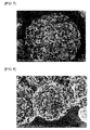
- spiny particles that are composite particles having a sea urchin-like shape in which carbon fibers are produced from the copper alloy powder are made.
- the production conditions of the composite particles are shown in the following Table 2 and Table 3. In Table 3 and Table 5 described later, composite particles 11 are redundantly described in order to make comparison with other composite particles easy, but the composition and making conditions of the composite particles 11 are not changed.
- AEROSIL 300 manufactured by NIPPON AEROSIL CO., LTD. was used. AEROSIL was added and mixed with the copper alloy powders A, C, E, and F as the pretreatment of step 1-A when the composite particles 11 to 15, 22 to 24, 32 to 35.42, and 43 were produced.
- the copper carbon fiber spiny particles obtained in steps 1-A, 1-B, and 1-C were further subjected to ball mill treatment and then subjected to re-CVD treatment as shown in Figure 2 .
- the catalyst precipitation step can be skipped, and therefore only step 2-A may be performed.
- epoxy resin in Table 4 a bisphenol A type epoxy resin (manufactured by Japan Epoxy Resin, trade name: EPIKOTE 828) was used.
- EPIKOTE 828 the imidazole curing agent
- 2P4MHZ manufactured by SHIKOKU CHEMICALS CORPORATION was used.
- BCA is an abbreviation of butyl cellosolve acetate
- DPMA is an abbreviation of dipropylene glycol methyl ether acetate.
- phenolic resin in Table 5 a known resol type phenolic resin (manufactured by Gun Ei Chemical Industry Co., Ltd., trade name: RESITOP PL-5208, phenol content 65%) used as the resin binder of a usual electroconductive paste was used.
- Example 11 is redundantly described in order to make the comparison of Examples 22 to 24, Examples 32 to 35, and Examples 42 and 43 with Example 11 easy, but the contents of Example 11 themselves are not changed.
- the specific resistance was measured by a low resistance digital multimeter using four point probe resistivity measurements after the electroconductive paste was applied to an epoxy substrate to a width of 2 mm, a length of 100 mm, and a thickness of 200 ⁇ m and thermally cured for 30 minutes.
- R is the resistance value of the digital multimeter
- S is the cross-sectional area of the coating film comprising the electroconductive paste
- L is the distance between the electrodes.
- the thermal curing was performed at temperatures of 120°C and 170°C for the epoxy resin and the phenolic resin, respectively. The results are shown in Figure 3 .
- Figure 14 is a diagram showing the results of specific resistance measurement under conditions without compression.
- Example 11 the amount of adhering carbon 0.7% (ethylene gas 2 minutes). It is seen that in Example 13: 1.5% (ethylene gas 4 minutes) and Example 14: 3.3% (ethylene gas 8 minutes) in which the amount of adhering carbon increases, the specific resistance increases compared with Example 11.
- the amount of adhering carbon in Example 15 (ethylene gas 0.25 minute) in which the amount of adhering carbon decreased was measured by weight increase before and after CVD but was an amount equal to or less than measurement variations.
- Example 15 it was confirmed that the color of the particles changed from copper to blackish brown due to carbon adhesion, and furthermore the adhesion of carbon was confirmed by measurement by an Auger electron spectrometer.
- Example 11 When Example 11 and Examples 22 to 24 were compared, good specific resistance was obtained in Example 11: the amount of cobalt in the alloy 1.0% by weight. When compared with Example 11, the specific resistance increased slightly in Example 24: an alloy of 0.88% by weight of cobalt and 0.93% by weight of iron, and the specific resistance increased greatly in Example 23: an alloy of 3.73% by weight of iron.
- Example 11 and Examples 32 to 35 are compared, it is seen that good specific resistance is obtained with a reheating temperature of 825°C or more in step 3-A.
- Example 11 When Example 11 and Examples 42 and 43 are compared, it is seen that the specific resistance is not greatly affected up to an amount of AEROSIL added of 1.0% by weight.
Landscapes
- Chemical & Material Sciences (AREA)
- Engineering & Computer Science (AREA)
- Organic Chemistry (AREA)
- Materials Engineering (AREA)
- Mechanical Engineering (AREA)
- Metallurgy (AREA)
- Dispersion Chemistry (AREA)
- Spectroscopy & Molecular Physics (AREA)
- Physics & Mathematics (AREA)
- Nanotechnology (AREA)
- General Chemical & Material Sciences (AREA)
- Life Sciences & Earth Sciences (AREA)
- Wood Science & Technology (AREA)
- Chemical Kinetics & Catalysis (AREA)
- Conductive Materials (AREA)
- Powder Metallurgy (AREA)
- Non-Insulated Conductors (AREA)
- Manufacture Of Metal Powder And Suspensions Thereof (AREA)
- Adhesives Or Adhesive Processes (AREA)
Applications Claiming Priority (3)
| Application Number | Priority Date | Filing Date | Title |
|---|---|---|---|
| JP2013160480 | 2013-08-01 | ||
| JP2013269465 | 2013-12-26 | ||
| PCT/JP2014/069901 WO2015016202A1 (fr) | 2013-08-01 | 2014-07-29 | Charge conductrice, son procédé de production, pâte conductrice et procédé de production de pâte conductrice |
Publications (3)
| Publication Number | Publication Date |
|---|---|
| EP3029686A1 true EP3029686A1 (fr) | 2016-06-08 |
| EP3029686A4 EP3029686A4 (fr) | 2017-03-22 |
| EP3029686B1 EP3029686B1 (fr) | 2020-09-02 |
Family
ID=52431735
Family Applications (1)
| Application Number | Title | Priority Date | Filing Date |
|---|---|---|---|
| EP14832327.2A Not-in-force EP3029686B1 (fr) | 2013-08-01 | 2014-07-29 | Charge conductrice, son procédé de production, pâte conductrice et procédé de production de pâte conductrice |
Country Status (7)
| Country | Link |
|---|---|
| US (1) | US10533098B2 (fr) |
| EP (1) | EP3029686B1 (fr) |
| JP (1) | JP5756887B1 (fr) |
| KR (1) | KR102166230B1 (fr) |
| CN (1) | CN105556617B (fr) |
| TW (1) | TWI604021B (fr) |
| WO (1) | WO2015016202A1 (fr) |
Cited By (3)
| Publication number | Priority date | Publication date | Assignee | Title |
|---|---|---|---|---|
| EP3115130A4 (fr) * | 2014-03-05 | 2017-10-25 | Sekisui Chemical Co., Ltd. | Charge conductrice, procédé de fabrication de charge conductrice, et bouillie conductrice |
| EP3648115A4 (fr) * | 2017-06-30 | 2021-03-24 | Sekisui Chemical Co., Ltd. | Pâte conductrice |
| CN113098163A (zh) * | 2021-04-19 | 2021-07-09 | 云南铜业压铸科技有限公司 | 一种高转速电动机用铸铜转子及其制备方法 |
Families Citing this family (7)
| Publication number | Priority date | Publication date | Assignee | Title |
|---|---|---|---|---|
| JP6457834B2 (ja) * | 2015-02-16 | 2019-01-23 | 積水化学工業株式会社 | 伝導性フィラー及びその製造方法並びに伝導性ペースト |
| JP6759632B2 (ja) * | 2015-03-31 | 2020-09-23 | 東レ株式会社 | 複合導電性粒子およびその製造方法ならびに導電性樹脂 |
| JP2016207377A (ja) * | 2015-04-20 | 2016-12-08 | 積水化学工業株式会社 | 導電性ペースト |
| JP6908398B2 (ja) * | 2017-03-08 | 2021-07-28 | 株式会社Adeka | 樹脂組成物、硬化物を形成する方法および硬化物 |
| CN114101659B (zh) * | 2021-12-06 | 2024-04-19 | 赵玉荣 | 一种铜合金碳纳米管复合材料及其制备方法和应用 |
| CN114334221B (zh) * | 2022-01-10 | 2024-02-09 | 珠海方正科技多层电路板有限公司 | 一种塞孔铜浆及其制备方法、印刷线路板 |
| CN115762849B (zh) * | 2022-11-14 | 2024-11-26 | 韩亚半导体材料(贵溪)有限公司 | 可气溶胶喷涂的太阳能电池用导电铜浆及其制备方法 |
Family Cites Families (25)
| Publication number | Priority date | Publication date | Assignee | Title |
|---|---|---|---|---|
| JPH07331360A (ja) * | 1994-06-06 | 1995-12-19 | Asahi Chem Ind Co Ltd | 新規な銅合金粉末及びその製造方法 |
| JPH07331125A (ja) * | 1994-06-08 | 1995-12-19 | Asahi Chem Ind Co Ltd | 導電性ペースト |
| JP2002008444A (ja) * | 2000-06-27 | 2002-01-11 | Hitachi Chem Co Ltd | 導電ペースト |
| JP2003268567A (ja) * | 2002-03-19 | 2003-09-25 | Hitachi Cable Ltd | 導電材被覆耐食性金属材料 |
| JP3984534B2 (ja) | 2002-11-19 | 2007-10-03 | 三井金属鉱業株式会社 | 導電性ペースト用の銅粉及びその製造方法 |
| JP3999676B2 (ja) | 2003-01-22 | 2007-10-31 | Dowaホールディングス株式会社 | 銅基合金およびその製造方法 |
| WO2004094700A1 (fr) * | 2003-02-18 | 2004-11-04 | Shinshu University | Particules metalliques et leur procede de production |
| KR100570634B1 (ko) | 2003-10-16 | 2006-04-12 | 한국전자통신연구원 | 탄소나노튜브와 금속분말 혼성 복합에 의해 제조된 전자파차폐재 |
| JP4390807B2 (ja) * | 2004-10-21 | 2009-12-24 | シナノケンシ株式会社 | 複合金属体及びその製造方法 |
| CN100499223C (zh) * | 2005-12-09 | 2009-06-10 | 中国科学院物理研究所 | 一种表面包覆碳的层状结构含锂复合金属氧化物及其应用 |
| JP4930986B2 (ja) | 2006-09-19 | 2012-05-16 | 独立行政法人産業技術総合研究所 | カーボンナノチューブの製造方法 |
| JP5173255B2 (ja) * | 2007-05-15 | 2013-04-03 | 石原産業株式会社 | 金属微粒子の製造方法及びその製造方法で得られた金属微粒子を含有した組成物。 |
| JP5077660B2 (ja) | 2007-07-25 | 2012-11-21 | 三菱マテリアル株式会社 | 金属粉末複合材を製造するコーティング組成物と、該金属粉末複合材によって製造された金属複合材、金属積層複合材、およびこれらの製造方法 |
| CN101801566B (zh) | 2007-09-14 | 2012-02-15 | 杰富意钢铁株式会社 | 粉末冶金用铁基粉末 |
| EP2223757A4 (fr) * | 2007-10-25 | 2013-03-13 | Univ Hokkaido Nat Univ Corp | Matériau métallique composite et son procédé de production |
| DE102008035756A1 (de) * | 2008-07-31 | 2010-02-04 | Robert Bosch Gmbh | Vorrichtung und Verfahren zum Reduzieren des Energieverbrauchs einer Maschine oder Anlage |
| KR101065778B1 (ko) | 2008-10-14 | 2011-09-20 | 한국과학기술연구원 | 탄소나노튜브 피복 실리콘-구리 복합 입자 및 그 제조 방법과, 이를 이용한 이차전지용 음극 및 이차전지 |
| FI20096317A0 (fi) | 2009-12-14 | 2009-12-14 | Valtion Teknillinen | Metallisten nanohiukkasten hiilipäällystysmenetelmä |
| KR101337994B1 (ko) | 2010-04-14 | 2013-12-06 | 한국과학기술원 | 그래핀/금속 나노 복합 분말 및 이의 제조 방법 |
| KR101310094B1 (ko) * | 2010-10-26 | 2013-09-24 | 한국과학기술연구원 | 구리 입자를 포함하는 탄소나노섬유, 나노입자, 분산용액 및 그 제조방법 |
| KR20130019196A (ko) | 2011-08-16 | 2013-02-26 | 삼성전기주식회사 | 금속 분말, 이의 제조 방법, 및 상기 금속 분말로 된 내부 전극을 포함하는 적층 세라믹 캐패시터 |
| JP2013091816A (ja) * | 2011-10-24 | 2013-05-16 | Katsuyoshi Kondo | 銅合金素材及びその製造方法 |
| JP2013091824A (ja) | 2011-10-25 | 2013-05-16 | Kri Inc | カーボン複合金属微粒子およびその製造方法 |
| US20160367971A1 (en) * | 2013-07-30 | 2016-12-22 | Northeastern University | Catalyst and Method for Synthesis of Carbon Nanomaterials |
| WO2015133474A1 (fr) | 2014-03-05 | 2015-09-11 | 積水化学工業株式会社 | Charge conductrice, procédé de fabrication de charge conductrice, et bouillie conductrice |
-
2014
- 2014-07-29 CN CN201480043505.4A patent/CN105556617B/zh not_active Expired - Fee Related
- 2014-07-29 JP JP2014538029A patent/JP5756887B1/ja active Active
- 2014-07-29 EP EP14832327.2A patent/EP3029686B1/fr not_active Not-in-force
- 2014-07-29 KR KR1020167002305A patent/KR102166230B1/ko not_active Expired - Fee Related
- 2014-07-29 WO PCT/JP2014/069901 patent/WO2015016202A1/fr not_active Ceased
- 2014-07-29 US US14/907,736 patent/US10533098B2/en not_active Expired - Fee Related
- 2014-08-01 TW TW103126493A patent/TWI604021B/zh not_active IP Right Cessation
Non-Patent Citations (1)
| Title |
|---|
| See references of WO2015016202A1 * |
Cited By (6)
| Publication number | Priority date | Publication date | Assignee | Title |
|---|---|---|---|---|
| EP3115130A4 (fr) * | 2014-03-05 | 2017-10-25 | Sekisui Chemical Co., Ltd. | Charge conductrice, procédé de fabrication de charge conductrice, et bouillie conductrice |
| US10639713B2 (en) | 2014-03-05 | 2020-05-05 | Sekisui Chemical Co., Ltd. | Conductive filler, method for manufacturing conductive filler, and conductive paste |
| EP3648115A4 (fr) * | 2017-06-30 | 2021-03-24 | Sekisui Chemical Co., Ltd. | Pâte conductrice |
| US10984921B2 (en) | 2017-06-30 | 2021-04-20 | Sekisui Chemical Co., Ltd. | Conductive paste |
| CN113098163A (zh) * | 2021-04-19 | 2021-07-09 | 云南铜业压铸科技有限公司 | 一种高转速电动机用铸铜转子及其制备方法 |
| CN113098163B (zh) * | 2021-04-19 | 2023-03-24 | 云南铜业压铸科技有限公司 | 一种高转速电动机用铸铜转子的制备方法 |
Also Published As
| Publication number | Publication date |
|---|---|
| KR20160037915A (ko) | 2016-04-06 |
| WO2015016202A1 (fr) | 2015-02-05 |
| CN105556617A (zh) | 2016-05-04 |
| KR102166230B1 (ko) | 2020-10-15 |
| EP3029686A4 (fr) | 2017-03-22 |
| TW201510110A (zh) | 2015-03-16 |
| JP5756887B1 (ja) | 2015-07-29 |
| TWI604021B (zh) | 2017-11-01 |
| CN105556617B (zh) | 2018-08-24 |
| EP3029686B1 (fr) | 2020-09-02 |
| US10533098B2 (en) | 2020-01-14 |
| US20160168395A1 (en) | 2016-06-16 |
| JPWO2015016202A1 (ja) | 2017-03-02 |
Similar Documents
| Publication | Publication Date | Title |
|---|---|---|
| EP3029686B1 (fr) | Charge conductrice, son procédé de production, pâte conductrice et procédé de production de pâte conductrice | |
| EP3816103B1 (fr) | Dispersion de nanotubes de carbone et son procédé de préparation | |
| KR101099237B1 (ko) | 전도성 페이스트와 이를 이용한 전도성 기판 | |
| CN105705276B (zh) | 铜粉 | |
| KR20180059490A (ko) | 도전성 페이스트 및 도전막 | |
| JP2022000522A (ja) | コア‐シェル構造の銀コーティングされた銅ナノワイヤを含むエポキシペースト組成物、およびそれを含む導電性フィルム | |
| EP3805153A1 (fr) | Nanotube de carbone, dispersion liquide de nanotubes de carbone et son utilisation | |
| TWI425893B (zh) | 銅配線圖案形成方法以及該方法所使用的氧化銅粒子分散液 | |
| TW201424887A (zh) | 混銀銅粉及其製造法、含有該混銀銅粉之導電性糊料、導電性接著劑、導電性膜、及電路 | |
| JP6530709B2 (ja) | 伝導性フィラー、伝導性フィラーの製造方法及び伝導性ペースト | |
| US10984921B2 (en) | Conductive paste | |
| JP6457834B2 (ja) | 伝導性フィラー及びその製造方法並びに伝導性ペースト | |
| CN101908388B (zh) | 纳米点状材料的形成方法 | |
| KR20180058903A (ko) | 절연 잉크 조성물 및 그를 이용하여 절연막이 형성된 기판 | |
| CN113242774B (zh) | 银浆 | |
| KR20130058205A (ko) | 그라파이트를 포함하는 전극형성용 금속 페이스트 조성물 및 이를 이용한 은-그라파이트 복합체 전극 | |
| CN113226595B (zh) | 银浆 | |
| JP2016207377A (ja) | 導電性ペースト | |
| CN113226596B (zh) | 银浆 | |
| KR20220100256A (ko) | 코어-쉘 형태의 전이금속 나노 입자-은 이 결합한 그래핀 복합체 및 이를 이용한 인쇄전자용 잉크. |
Legal Events
| Date | Code | Title | Description |
|---|---|---|---|
| PUAI | Public reference made under article 153(3) epc to a published international application that has entered the european phase |
Free format text: ORIGINAL CODE: 0009012 |
|
| 17P | Request for examination filed |
Effective date: 20160125 |
|
| AK | Designated contracting states |
Kind code of ref document: A1 Designated state(s): AL AT BE BG CH CY CZ DE DK EE ES FI FR GB GR HR HU IE IS IT LI LT LU LV MC MK MT NL NO PL PT RO RS SE SI SK SM TR |
|
| AX | Request for extension of the european patent |
Extension state: BA ME |
|
| DAX | Request for extension of the european patent (deleted) | ||
| A4 | Supplementary search report drawn up and despatched |
Effective date: 20170217 |
|
| RIC1 | Information provided on ipc code assigned before grant |
Ipc: B22F 1/00 20060101ALI20170213BHEP Ipc: B22F 1/02 20060101ALI20170213BHEP Ipc: H01B 1/22 20060101ALI20170213BHEP Ipc: C22C 9/00 20060101AFI20170213BHEP Ipc: C22C 1/04 20060101ALI20170213BHEP Ipc: C22C 9/06 20060101ALN20170213BHEP |
|
| STAA | Information on the status of an ep patent application or granted ep patent |
Free format text: STATUS: EXAMINATION IS IN PROGRESS |
|
| 17Q | First examination report despatched |
Effective date: 20180409 |
|
| REG | Reference to a national code |
Ref country code: DE Ref legal event code: R079 Ref document number: 602014069801 Country of ref document: DE Free format text: PREVIOUS MAIN CLASS: H01B0005000000 Ipc: C22C0009000000 |
|
| GRAP | Despatch of communication of intention to grant a patent |
Free format text: ORIGINAL CODE: EPIDOSNIGR1 |
|
| STAA | Information on the status of an ep patent application or granted ep patent |
Free format text: STATUS: GRANT OF PATENT IS INTENDED |
|
| RIC1 | Information provided on ipc code assigned before grant |
Ipc: C22C 1/04 20060101ALI20200124BHEP Ipc: C22C 9/06 20060101ALN20200124BHEP Ipc: B22F 1/02 20060101ALI20200124BHEP Ipc: B22F 1/00 20060101ALI20200124BHEP Ipc: H01B 1/22 20060101ALI20200124BHEP Ipc: C22C 9/00 20060101AFI20200124BHEP |
|
| INTG | Intention to grant announced |
Effective date: 20200303 |
|
| GRAS | Grant fee paid |
Free format text: ORIGINAL CODE: EPIDOSNIGR3 |
|
| GRAA | (expected) grant |
Free format text: ORIGINAL CODE: 0009210 |
|
| STAA | Information on the status of an ep patent application or granted ep patent |
Free format text: STATUS: THE PATENT HAS BEEN GRANTED |
|
| AK | Designated contracting states |
Kind code of ref document: B1 Designated state(s): AL AT BE BG CH CY CZ DE DK EE ES FI FR GB GR HR HU IE IS IT LI LT LU LV MC MK MT NL NO PL PT RO RS SE SI SK SM TR |
|
| REG | Reference to a national code |
Ref country code: GB Ref legal event code: FG4D |
|
| REG | Reference to a national code |
Ref country code: AT Ref legal event code: REF Ref document number: 1308871 Country of ref document: AT Kind code of ref document: T Effective date: 20200915 Ref country code: CH Ref legal event code: EP |
|
| REG | Reference to a national code |
Ref country code: DE Ref legal event code: R096 Ref document number: 602014069801 Country of ref document: DE |
|
| REG | Reference to a national code |
Ref country code: IE Ref legal event code: FG4D |
|
| REG | Reference to a national code |
Ref country code: LT Ref legal event code: MG4D |
|
| PG25 | Lapsed in a contracting state [announced via postgrant information from national office to epo] |
Ref country code: FI Free format text: LAPSE BECAUSE OF FAILURE TO SUBMIT A TRANSLATION OF THE DESCRIPTION OR TO PAY THE FEE WITHIN THE PRESCRIBED TIME-LIMIT Effective date: 20200902 Ref country code: SE Free format text: LAPSE BECAUSE OF FAILURE TO SUBMIT A TRANSLATION OF THE DESCRIPTION OR TO PAY THE FEE WITHIN THE PRESCRIBED TIME-LIMIT Effective date: 20200902 Ref country code: BG Free format text: LAPSE BECAUSE OF FAILURE TO SUBMIT A TRANSLATION OF THE DESCRIPTION OR TO PAY THE FEE WITHIN THE PRESCRIBED TIME-LIMIT Effective date: 20201202 Ref country code: NO Free format text: LAPSE BECAUSE OF FAILURE TO SUBMIT A TRANSLATION OF THE DESCRIPTION OR TO PAY THE FEE WITHIN THE PRESCRIBED TIME-LIMIT Effective date: 20201202 Ref country code: GR Free format text: LAPSE BECAUSE OF FAILURE TO SUBMIT A TRANSLATION OF THE DESCRIPTION OR TO PAY THE FEE WITHIN THE PRESCRIBED TIME-LIMIT Effective date: 20201203 Ref country code: LT Free format text: LAPSE BECAUSE OF FAILURE TO SUBMIT A TRANSLATION OF THE DESCRIPTION OR TO PAY THE FEE WITHIN THE PRESCRIBED TIME-LIMIT Effective date: 20200902 Ref country code: HR Free format text: LAPSE BECAUSE OF FAILURE TO SUBMIT A TRANSLATION OF THE DESCRIPTION OR TO PAY THE FEE WITHIN THE PRESCRIBED TIME-LIMIT Effective date: 20200902 |
|
| REG | Reference to a national code |
Ref country code: NL Ref legal event code: MP Effective date: 20200902 |
|
| REG | Reference to a national code |
Ref country code: AT Ref legal event code: MK05 Ref document number: 1308871 Country of ref document: AT Kind code of ref document: T Effective date: 20200902 |
|
| PG25 | Lapsed in a contracting state [announced via postgrant information from national office to epo] |
Ref country code: PL Free format text: LAPSE BECAUSE OF FAILURE TO SUBMIT A TRANSLATION OF THE DESCRIPTION OR TO PAY THE FEE WITHIN THE PRESCRIBED TIME-LIMIT Effective date: 20200902 Ref country code: LV Free format text: LAPSE BECAUSE OF FAILURE TO SUBMIT A TRANSLATION OF THE DESCRIPTION OR TO PAY THE FEE WITHIN THE PRESCRIBED TIME-LIMIT Effective date: 20200902 Ref country code: RS Free format text: LAPSE BECAUSE OF FAILURE TO SUBMIT A TRANSLATION OF THE DESCRIPTION OR TO PAY THE FEE WITHIN THE PRESCRIBED TIME-LIMIT Effective date: 20200902 |
|
| PG25 | Lapsed in a contracting state [announced via postgrant information from national office to epo] |
Ref country code: PT Free format text: LAPSE BECAUSE OF FAILURE TO SUBMIT A TRANSLATION OF THE DESCRIPTION OR TO PAY THE FEE WITHIN THE PRESCRIBED TIME-LIMIT Effective date: 20210104 Ref country code: NL Free format text: LAPSE BECAUSE OF FAILURE TO SUBMIT A TRANSLATION OF THE DESCRIPTION OR TO PAY THE FEE WITHIN THE PRESCRIBED TIME-LIMIT Effective date: 20200902 Ref country code: EE Free format text: LAPSE BECAUSE OF FAILURE TO SUBMIT A TRANSLATION OF THE DESCRIPTION OR TO PAY THE FEE WITHIN THE PRESCRIBED TIME-LIMIT Effective date: 20200902 Ref country code: RO Free format text: LAPSE BECAUSE OF FAILURE TO SUBMIT A TRANSLATION OF THE DESCRIPTION OR TO PAY THE FEE WITHIN THE PRESCRIBED TIME-LIMIT Effective date: 20200902 Ref country code: SM Free format text: LAPSE BECAUSE OF FAILURE TO SUBMIT A TRANSLATION OF THE DESCRIPTION OR TO PAY THE FEE WITHIN THE PRESCRIBED TIME-LIMIT Effective date: 20200902 Ref country code: CZ Free format text: LAPSE BECAUSE OF FAILURE TO SUBMIT A TRANSLATION OF THE DESCRIPTION OR TO PAY THE FEE WITHIN THE PRESCRIBED TIME-LIMIT Effective date: 20200902 |
|
| PG25 | Lapsed in a contracting state [announced via postgrant information from national office to epo] |
Ref country code: ES Free format text: LAPSE BECAUSE OF FAILURE TO SUBMIT A TRANSLATION OF THE DESCRIPTION OR TO PAY THE FEE WITHIN THE PRESCRIBED TIME-LIMIT Effective date: 20200902 Ref country code: AT Free format text: LAPSE BECAUSE OF FAILURE TO SUBMIT A TRANSLATION OF THE DESCRIPTION OR TO PAY THE FEE WITHIN THE PRESCRIBED TIME-LIMIT Effective date: 20200902 Ref country code: AL Free format text: LAPSE BECAUSE OF FAILURE TO SUBMIT A TRANSLATION OF THE DESCRIPTION OR TO PAY THE FEE WITHIN THE PRESCRIBED TIME-LIMIT Effective date: 20200902 Ref country code: IS Free format text: LAPSE BECAUSE OF FAILURE TO SUBMIT A TRANSLATION OF THE DESCRIPTION OR TO PAY THE FEE WITHIN THE PRESCRIBED TIME-LIMIT Effective date: 20210102 |
|
| REG | Reference to a national code |
Ref country code: DE Ref legal event code: R097 Ref document number: 602014069801 Country of ref document: DE |
|
| PG25 | Lapsed in a contracting state [announced via postgrant information from national office to epo] |
Ref country code: SK Free format text: LAPSE BECAUSE OF FAILURE TO SUBMIT A TRANSLATION OF THE DESCRIPTION OR TO PAY THE FEE WITHIN THE PRESCRIBED TIME-LIMIT Effective date: 20200902 |
|
| PLBE | No opposition filed within time limit |
Free format text: ORIGINAL CODE: 0009261 |
|
| STAA | Information on the status of an ep patent application or granted ep patent |
Free format text: STATUS: NO OPPOSITION FILED WITHIN TIME LIMIT |
|
| 26N | No opposition filed |
Effective date: 20210603 |
|
| PG25 | Lapsed in a contracting state [announced via postgrant information from national office to epo] |
Ref country code: SI Free format text: LAPSE BECAUSE OF FAILURE TO SUBMIT A TRANSLATION OF THE DESCRIPTION OR TO PAY THE FEE WITHIN THE PRESCRIBED TIME-LIMIT Effective date: 20200902 Ref country code: DK Free format text: LAPSE BECAUSE OF FAILURE TO SUBMIT A TRANSLATION OF THE DESCRIPTION OR TO PAY THE FEE WITHIN THE PRESCRIBED TIME-LIMIT Effective date: 20200902 |
|
| PG25 | Lapsed in a contracting state [announced via postgrant information from national office to epo] |
Ref country code: IT Free format text: LAPSE BECAUSE OF FAILURE TO SUBMIT A TRANSLATION OF THE DESCRIPTION OR TO PAY THE FEE WITHIN THE PRESCRIBED TIME-LIMIT Effective date: 20200902 |
|
| REG | Reference to a national code |
Ref country code: CH Ref legal event code: PL |
|
| GBPC | Gb: european patent ceased through non-payment of renewal fee |
Effective date: 20210729 |
|
| PG25 | Lapsed in a contracting state [announced via postgrant information from national office to epo] |
Ref country code: MC Free format text: LAPSE BECAUSE OF FAILURE TO SUBMIT A TRANSLATION OF THE DESCRIPTION OR TO PAY THE FEE WITHIN THE PRESCRIBED TIME-LIMIT Effective date: 20200902 |
|
| REG | Reference to a national code |
Ref country code: BE Ref legal event code: MM Effective date: 20210731 |
|
| PG25 | Lapsed in a contracting state [announced via postgrant information from national office to epo] |
Ref country code: LI Free format text: LAPSE BECAUSE OF NON-PAYMENT OF DUE FEES Effective date: 20210731 Ref country code: GB Free format text: LAPSE BECAUSE OF NON-PAYMENT OF DUE FEES Effective date: 20210729 Ref country code: CH Free format text: LAPSE BECAUSE OF NON-PAYMENT OF DUE FEES Effective date: 20210731 |
|
| PG25 | Lapsed in a contracting state [announced via postgrant information from national office to epo] |
Ref country code: LU Free format text: LAPSE BECAUSE OF NON-PAYMENT OF DUE FEES Effective date: 20210729 Ref country code: FR Free format text: LAPSE BECAUSE OF NON-PAYMENT OF DUE FEES Effective date: 20210731 |
|
| PG25 | Lapsed in a contracting state [announced via postgrant information from national office to epo] |
Ref country code: IE Free format text: LAPSE BECAUSE OF NON-PAYMENT OF DUE FEES Effective date: 20210729 Ref country code: BE Free format text: LAPSE BECAUSE OF NON-PAYMENT OF DUE FEES Effective date: 20210731 |
|
| PG25 | Lapsed in a contracting state [announced via postgrant information from national office to epo] |
Ref country code: HU Free format text: LAPSE BECAUSE OF FAILURE TO SUBMIT A TRANSLATION OF THE DESCRIPTION OR TO PAY THE FEE WITHIN THE PRESCRIBED TIME-LIMIT; INVALID AB INITIO Effective date: 20140729 |
|
| PG25 | Lapsed in a contracting state [announced via postgrant information from national office to epo] |
Ref country code: CY Free format text: LAPSE BECAUSE OF FAILURE TO SUBMIT A TRANSLATION OF THE DESCRIPTION OR TO PAY THE FEE WITHIN THE PRESCRIBED TIME-LIMIT Effective date: 20200902 |
|
| PGFP | Annual fee paid to national office [announced via postgrant information from national office to epo] |
Ref country code: DE Payment date: 20230607 Year of fee payment: 10 |
|
| PG25 | Lapsed in a contracting state [announced via postgrant information from national office to epo] |
Ref country code: MK Free format text: LAPSE BECAUSE OF FAILURE TO SUBMIT A TRANSLATION OF THE DESCRIPTION OR TO PAY THE FEE WITHIN THE PRESCRIBED TIME-LIMIT Effective date: 20200902 |
|
| PG25 | Lapsed in a contracting state [announced via postgrant information from national office to epo] |
Ref country code: TR Free format text: LAPSE BECAUSE OF FAILURE TO SUBMIT A TRANSLATION OF THE DESCRIPTION OR TO PAY THE FEE WITHIN THE PRESCRIBED TIME-LIMIT Effective date: 20200902 |
|
| PG25 | Lapsed in a contracting state [announced via postgrant information from national office to epo] |
Ref country code: MT Free format text: LAPSE BECAUSE OF FAILURE TO SUBMIT A TRANSLATION OF THE DESCRIPTION OR TO PAY THE FEE WITHIN THE PRESCRIBED TIME-LIMIT Effective date: 20200902 |
|
| REG | Reference to a national code |
Ref country code: DE Ref legal event code: R119 Ref document number: 602014069801 Country of ref document: DE |
|
| PG25 | Lapsed in a contracting state [announced via postgrant information from national office to epo] |
Ref country code: DE Free format text: LAPSE BECAUSE OF NON-PAYMENT OF DUE FEES Effective date: 20250201 |