EP3029687A1 - Schmelzbarer verbindungskabelbaum und systeme und verfahren zur adressierung schmelzbarer verbindungskabelbäume - Google Patents
Schmelzbarer verbindungskabelbaum und systeme und verfahren zur adressierung schmelzbarer verbindungskabelbäume Download PDFInfo
- Publication number
- EP3029687A1 EP3029687A1 EP15195741.2A EP15195741A EP3029687A1 EP 3029687 A1 EP3029687 A1 EP 3029687A1 EP 15195741 A EP15195741 A EP 15195741A EP 3029687 A1 EP3029687 A1 EP 3029687A1
- Authority
- EP
- European Patent Office
- Prior art keywords
- fusible link
- fusible
- pins
- link cable
- connector
- Prior art date
- Legal status (The legal status is an assumption and is not a legal conclusion. Google has not performed a legal analysis and makes no representation as to the accuracy of the status listed.)
- Withdrawn
Links
- 238000000034 method Methods 0.000 title claims abstract description 9
- 238000010586 diagram Methods 0.000 description 4
- 239000000463 material Substances 0.000 description 3
- RYGMFSIKBFXOCR-UHFFFAOYSA-N Copper Chemical compound [Cu] RYGMFSIKBFXOCR-UHFFFAOYSA-N 0.000 description 2
- 230000008901 benefit Effects 0.000 description 2
- 230000008859 change Effects 0.000 description 2
- 229910052802 copper Inorganic materials 0.000 description 2
- 239000010949 copper Substances 0.000 description 2
- 230000004913 activation Effects 0.000 description 1
- 239000000956 alloy Substances 0.000 description 1
- 229910045601 alloy Inorganic materials 0.000 description 1
- 238000004891 communication Methods 0.000 description 1
- 230000007246 mechanism Effects 0.000 description 1
- 229910052751 metal Inorganic materials 0.000 description 1
- 239000002184 metal Substances 0.000 description 1
- 150000002739 metals Chemical class 0.000 description 1
- 238000007747 plating Methods 0.000 description 1
- 230000004044 response Effects 0.000 description 1
Images



Classifications
-
- H—ELECTRICITY
- H01—ELECTRIC ELEMENTS
- H01R—ELECTRICALLY-CONDUCTIVE CONNECTIONS; STRUCTURAL ASSOCIATIONS OF A PLURALITY OF MUTUALLY-INSULATED ELECTRICAL CONNECTING ELEMENTS; COUPLING DEVICES; CURRENT COLLECTORS
- H01R13/00—Details of coupling devices of the kinds covered by groups H01R12/70 or H01R24/00 - H01R33/00
- H01R13/66—Structural association with built-in electrical component
- H01R13/70—Structural association with built-in electrical component with built-in switch
-
- H—ELECTRICITY
- H01—ELECTRIC ELEMENTS
- H01R—ELECTRICALLY-CONDUCTIVE CONNECTIONS; STRUCTURAL ASSOCIATIONS OF A PLURALITY OF MUTUALLY-INSULATED ELECTRICAL CONNECTING ELEMENTS; COUPLING DEVICES; CURRENT COLLECTORS
- H01R13/00—Details of coupling devices of the kinds covered by groups H01R12/70 or H01R24/00 - H01R33/00
- H01R13/66—Structural association with built-in electrical component
- H01R13/68—Structural association with built-in electrical component with built-in fuse
-
- H—ELECTRICITY
- H01—ELECTRIC ELEMENTS
- H01H—ELECTRIC SWITCHES; RELAYS; SELECTORS; EMERGENCY PROTECTIVE DEVICES
- H01H85/00—Protective devices in which the current flows through a part of fusible material and this current is interrupted by displacement of the fusible material when this current becomes excessive
- H01H85/02—Details
- H01H85/46—Circuit arrangements not adapted to a particular application of the protective device
-
- H—ELECTRICITY
- H01—ELECTRIC ELEMENTS
- H01R—ELECTRICALLY-CONDUCTIVE CONNECTIONS; STRUCTURAL ASSOCIATIONS OF A PLURALITY OF MUTUALLY-INSULATED ELECTRICAL CONNECTING ELEMENTS; COUPLING DEVICES; CURRENT COLLECTORS
- H01R13/00—Details of coupling devices of the kinds covered by groups H01R12/70 or H01R24/00 - H01R33/00
- H01R13/66—Structural association with built-in electrical component
- H01R13/665—Structural association with built-in electrical component with built-in electronic circuit
- H01R13/6675—Structural association with built-in electrical component with built-in electronic circuit with built-in power supply
-
- H—ELECTRICITY
- H01—ELECTRIC ELEMENTS
- H01R—ELECTRICALLY-CONDUCTIVE CONNECTIONS; STRUCTURAL ASSOCIATIONS OF A PLURALITY OF MUTUALLY-INSULATED ELECTRICAL CONNECTING ELEMENTS; COUPLING DEVICES; CURRENT COLLECTORS
- H01R13/00—Details of coupling devices of the kinds covered by groups H01R12/70 or H01R24/00 - H01R33/00
- H01R13/66—Structural association with built-in electrical component
- H01R13/665—Structural association with built-in electrical component with built-in electronic circuit
- H01R13/6691—Structural association with built-in electrical component with built-in electronic circuit with built-in signalling means
-
- H—ELECTRICITY
- H01—ELECTRIC ELEMENTS
- H01R—ELECTRICALLY-CONDUCTIVE CONNECTIONS; STRUCTURAL ASSOCIATIONS OF A PLURALITY OF MUTUALLY-INSULATED ELECTRICAL CONNECTING ELEMENTS; COUPLING DEVICES; CURRENT COLLECTORS
- H01R31/00—Coupling parts supported only by co-operation with counterpart
- H01R31/06—Intermediate parts for linking two coupling parts, e.g. adapter
- H01R31/065—Intermediate parts for linking two coupling parts, e.g. adapter with built-in electric apparatus
-
- B—PERFORMING OPERATIONS; TRANSPORTING
- B60—VEHICLES IN GENERAL
- B60R—VEHICLES, VEHICLE FITTINGS, OR VEHICLE PARTS, NOT OTHERWISE PROVIDED FOR
- B60R16/00—Electric or fluid circuits specially adapted for vehicles and not otherwise provided for; Arrangement of elements of electric or fluid circuits specially adapted for vehicles and not otherwise provided for
- B60R16/02—Electric or fluid circuits specially adapted for vehicles and not otherwise provided for; Arrangement of elements of electric or fluid circuits specially adapted for vehicles and not otherwise provided for electric constitutive elements
- B60R16/0207—Wire harnesses
-
- H—ELECTRICITY
- H01—ELECTRIC ELEMENTS
- H01R—ELECTRICALLY-CONDUCTIVE CONNECTIONS; STRUCTURAL ASSOCIATIONS OF A PLURALITY OF MUTUALLY-INSULATED ELECTRICAL CONNECTING ELEMENTS; COUPLING DEVICES; CURRENT COLLECTORS
- H01R2201/00—Connectors or connections adapted for particular applications
- H01R2201/26—Connectors or connections adapted for particular applications for vehicles
Definitions
- the present disclosure generally relates tocables, and more particularly relates toaddressing cables in line replaceable unit environments.
- Line replaceable unit systems utilize modular components (i.e., line replaceable units) so that equipment that is experiencing a fault or is scheduled to be upgraded can be easily changed.
- line replaceable units modular components
- addressing each line replaceable unit can be time consuming.
- a fusible link cable harnesses may include, but is not limited to, a first connector having a plurality of pins, the plurality of pins comprising a main addressing pin and a plurality of secondary addressing pins, and a fusible link board, the fusible link board including, but not limited to, a bus coupled to the main addressing pin, and a plurality of fusible links, each of the plurality of fusible links coupled between one of the secondary addressing pins and the bus.
- an ID burning device may include, but is not limited to, a connector configured to receive a fusible link cable harnesseshaving a fusible link board, the connector having a plurality of pins, a plurality of switches, each of the plurality of switches selectably connected to one of the plurality of pins, and a power supply electrically coupled to the plurality of switches, the power supply configured to output a predefined current to the switches which are selected to be coupled to a respective on of the plurality of pins, the predefined current being greater than a current threshold of a fusible link on the fusible link board.
- a method for assigning an address to a received fusible link cable harness may include, but is not limited to, receiving, by a controller, one of an address or a switch selection, connecting, by the controller, a power supply to fusible links of the received fusible link cable harness via a plurality of switches according to the received one of the address or the switch selection, and applying, by the power supply, a current above a current threshold of the fusible links of the received fusible link cable harness to assign the address to the fusible link cable harness.
- a fusible link cable harness is provided.
- the fusible link cable harness can be used to connect a line replaceable unit to a central interface unit in various environments.
- the fusible link cable harness includes fusible links coupled to certain pins of the fusible link cable harness. By simply applying a current to some of the fusible links, an address and or a configurable option can be assigned to the fusible link cable harness such that a line replaceable unit coupled to the fusible link cable harness can be addressed or have configurable options selected.
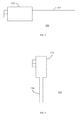
- FIG. 1 is a block diagram of a line replaceable unit system 100, in accordance with an embodiment.
- the line replaceable unit system 100 may be part of an aircraft, watercraft or spacecraft.
- the line replaceable unit system 100 may be implemented in any operation environment, including, but not limited to, vehicular settings, commercial settings or industrial settings.
- the line replaceable unit system 100 includes multiple line replaceable units (LRU's) 110.
- Each LRU 110 is a modular component designed to be replaced quickly in the operating environment.
- an LRU 110 may be part of an in-flight entertainment system, such as a Blu-ray player, an in seat display or overhead display, a network switch, or the like.
- the LRU 110 could also be a radio or other auxiliary equipment in a vehicle.
- the LRU 110 could also be a configurable device that once configured via a fusible link would operate to an assigned task.
- the LRU 110 may be capable of performing multiple tasks or offering multiple services and can be programmed to execute a subset of the tasks and/or offer a subset of the services based upon an address assigned to the LRU 110, as discussed in further detail below.
- Each LRU 110 is coupled to a central interface unit (CIU) 120.
- the CIU 120 coordinates communication with each LRU 110 with other components, such as a processor or a controller, in the operation environment of the line replaceable unit system 100.
- the LRU's 110 are designed to be easily replaceable to minimize downtime of the operating environment, the LRU's 110 do not have unique addresses associated with themselves.
- Typical CIU's 120 will direct a command to a LRU 110 based upon an address associated with a handmade cable harness coupled between the LRU 110 and the CIU 120.
- the handmade cables harnesses are costly to make and time consuming to replace. Accordingly, the line replaceable unit system 100 illustrated in FIG. 1 utilizes a fusible link cable harness 130 to connect the LRU's to the CIU 120.
- the fusible link cable harness 130 includes a connector housing 132 and a cable 134.
- the connector housing 132 includes the connector for connecting the fusible link cable harness 130 to a LRU 110 and the CIU 120.
- the connector housing 132 may be a 25-pin D-sub cable connector.
- the connector housing 132 further includes a fusible link board (not illustrated in FIG. 1 ) for assigning an address to the fusible link cable harness 130.
- the LRU 110 willbe addressedby the fusible link cable harness 130 by reading an address from one or more pins in the connector housing 132, as discussed in further detail below.
- FIG. 2 is an end view ofan exemplary connector housing 132 for a fusible link cable harness 130, in accordance with an embodiment.
- the connector housing 132 includes a connector 200.
- the connector 200 is a 25-pin D-sub connector.
- the number of pins and the configuration of the connector can vary. In one embodiment, for example, only a subset of the pins, labeled 1-25, are connected to a small printed circuit board inside the connector.
- the connector housing 132 may be a straight through style connector where the cable 134 exits a back of the connector housing 132.
- FIG. 3 illustrates an exemplary straight through style connector housing 132.
- the connector housing 132 may be a right angle style connector where the cable 134 exits from the bottom or top of the connector, the cable could also exit to the right or left of the housing 132.
- FIG. 4 illustrates an exemplary right angle style connector housing 132, in accordance with an embodiment. However, one of ordinary skill in the art would recognize that the proportions and features of the connector housing 132 can vary.
- the connector housing 132 further includes a fusible link board 210.
- the fusible link board 210 may be a flexible or a rigid printed circuit board (PCB). While the fusible link board 210 is illustrated as being in a plane parallel to the face of the connector 200, one ofordinary skill in the art would recognize that the respective orientations of the fusible link board 210 and connector 200 could vary.
- the fusible link board 210 is connected to a subset of the pins of the connector 200.
- the subset of pins are used as addressing pins for assigning an address to the fusible link cable harness 130, however this subset of pins could also be used to assign a functional configuration to the LRU 110.
- the fusible link board 210 connects pins 3-11, 14 and 17.
- the assignment of pins and the number of pins used as addressing pins can vary.
- pin 14 is assigned as the main addressing pin.
- the other addressing pins i.e., pins 3-11 and 17 are assigned as secondary addressing pins.
- the LRU110 determines the address associated with the fusible link cable harness 130 based upon a determination of which of the secondary addressing pins are resistively coupled to the main addressing pin. In one embodiment, for example, if asecondary addressing pin is connected to the main addressing pin, the LRU 110will associate a one with the respective pin and if the secondary addressing pin is not connected to the main addressing pin the LRU110 will associate a zero with the respective pin.
- the LRU110 will associate a zero with the respective pin and if the secondary addressing pin is not connected to the main addressing pin the LRU 110 will associate a one with the respective pin.
- an Ovation Select addressing system may use an eleven bit binary address.
- the LRU 110 may have an internal pull up resistor connected to each of the eleven address pins in the connector, for example, pins 3-11 and 17.
- Pin 14, for example on the LRU 110 is at a ground potential so that if it is connected to any of the address lines the binary bit for that position will be a "0" if it is not connected to that position the LRU internal pull up resistors will hold the binary bit up to be read as a "1".
- the CIU 120 send the same commands to every port.
- the LRU 110 determines which commands to execute based upon addresses associated with the commands.
- the LRU 110 can add its address, which is based upon the address associated with the fusible link cable harness 130, to data sent to the CIU 120 so that the CIU can determine where the data came from.
- the fusible link board 210 includes a bus 220.
- the bus 220 is connected to the main addressing pin, in this example, pin 14.
- the bus 220 is a trace on the fusible link board 210 having a predetermined thickness.
- Each of the secondary addressing pins are connected to the first bus 220 through fusible links 230.
- the fusible links 230 are designed to pass electrical current below a predetermined amperage (i.e., a current threshold) and to permanentlyopen (i.e., burn out) in response to receiving the current above the predetermined amperage.
- the fusible links 230 may be traces thinner than the thickness of the first bus 220, as discussed in further detail below.
- Traditional fuses are typically too large and switches tend to fail in high vibration and temperature environments. Accordingly, by utilizing traces of different sizes on a small printed circuit board, a permanent and easy solution to produce an address or configuration selection mechanism is achieved.
- the fusible links 230 are purposefully broken.
- a current may be applied to a selected subset of the addressing pins to break selected fusible links 230.
- the bus 220 may be a trace which is 2mm wide on the fusible link board 210 while the fusible links may be a trace which is less than around 0.5mm thick.
- the width of the traces designed to be fusible (i.e., the fusible links 230) and the width of the traces designed not to be fusible (i.e., the bus 220) can vary depending upon the current applied to break the fusible links 230.
- the materials of the traces of the bus 220 and the fusible links 230 could also vary.
- the traces of the bus and/or fusible links 230 could be made of pin plating.
- the traces of the bus and/or fusible links 230 could be made of copper clad, or other materials depending on the severity of the intended environments.
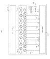
- FIG. 5 is a block diagram of an ID burning device 500, in accordance with an embodiment.
- the ID burning device 500 could be, for example, a portable device or could be situated in a workstation.
- the ID burning device 500 includes at least one connector 510 corresponding to the connector 200 of the fusible link cable harness 130.
- the connector 510 is a twenty-five pin D-sub connector.
- the connector 510 can vary depending upon the expected connector 510 of thefusible link cable harness 130.
- the ID burning device 500 may have multiple connectors 510 for different styles of fusible link cable harnesses 130.
- the ID burning device 500 may have an interchangeable connector 510 which can be switched out according to the fusible link cable harness 130 to be programed.
- the ID burning device 500 further includes a power supply 520.
- the power supply 520 applies a current to selected addressing pins of the fusible link cable harness 130.
- the ID burning device 500 may include multiple switches 530. Each of the switches 530 may be coupled between the power supply 520 and a pin of the connector 510. Accordingly, a user of the ID burning device 500 can assign an address to a fusible link cable harness 130coupled to the connector 510 by opening and/or closing the switches 530. In this embodiment, for example, all of the selected address pins could receive the programming current simultaneously. However, in other embodiments, the ID burning device 500 may only have a single switch 530 which is movable between the pins of the connector 510. In this embodiment, the power supply 520 would assign an address bit to each fusible link 230 individually.
- the amperage output by the power supply 520 can be selected such that the fusible links 230 of the fusible link cable harness 130 would be opened when connected to the power supply 520 without damaging the bus 220.
- the amperage output by the power supply 520 would disconnect the selected secondary address pins of the fusible link cable harness 130 from the main address pin by applying a current above a current threshold of a respective fusible link 230, thereby assigning the address to the fusible link cable harness 130, without damaging other components in the fusible link cable harness 130.
- a return line 540 coupled between pin 14 of the connector 510 and the power supply 520 completes the circuit.
- the power supply 520 may output a five amp signal.
- a straight DC amperage should be sufficient to break a fusible link 230 made from, for example, copper clad.
- other methods, including AC may prove better for breaking a fusible link 230.
- the amperage and type of waveform can vary depending upon the respective current threshold of the bus 220, the material used to form the fusible links 230 and any other components of the fusible link cable harness 130.
- the switches 530 may be manually operated by a user. In other words, a technician would be able to manually couple or decouple the pins of the connector 510 by opening or closing a respective switch.
- the switches 530 may be operable by a controller 550.
- the controller 550 may include a processor, such as a central processing unit (CPU), a microcontroller, an application specific integrated circuit (ASIC), a field programmable gate array (FPGA), or any other logic device or combination thereof.
- the controller 550 may selectively open and close the switches 530 based upon input from an input device 560.
- the input device 560 may be, for example, a keyboard, a touch screen, a mouse, a display, or the like, or any combination thereof.
- an operator of the ID burning device 500 could either enter an address to the controller 550 through an input device 560.
- the controller 550 would then determine which of the switches 530 to open and close in order the implement the address burn-in via the power supply 520.
- an operator could simply select which switches 530 to open or close through the input device 560.
- the controller 550 could also be coupled to the power supply 520.
- the controller 550 may determine when to activate the power supply 520 to output the programming current.
- the controller 550 may automatically activate the power supply 520 after controlling the switches 530 based upon input the switch selection or address selection from the input device 560, or may activate the power supply 520 after receiving a specific activation command through the input device 560.
- the ID burning device 500 may further include an ID reader 570.
- the ID reader 570 may be configured to read the address from a fusible link cable harness 130 in the same manner as the LRU110 to verify that the address assigned to the fusible link cable harness 130 was correctly assigned.
- the ID reader 570 may be coupled to the same connector 510 used to assigned the address to the fusible link cable harness 130.
- the ID reader 570 may utilize a different connector (not illustrated).
- the ID reader 570could include a display for outputting the address assigned to the fusible link cable harnesses 130.
- the display could be an LCD display, an OLED display, or any other display capable of displaying the address.
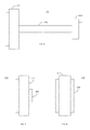
- FIG. 6 illustrates another exemplary fusible link cable harness 130 in accordance with an embodiment.
- the fusible link cable harness 130 includes a connector housing 132 as discussed above on one side of a cable 134 and a second connector housing 600 on a second side of the cable 134.
- the second connector housing 600 may be a 9-pin D-sub connector.
- the pins are not used to transfer data between the LRU 110 and the CIU 120. Accordingly, only a subset of the pins of the connector housing 132 would be required to be connected to the second connector housing 600.
- One advantage of this embodiment is that any LRU 110 connected in this manner would only require smaller (e.g., a 9-pin D-sub connector) connector, reducing the size, weight and cost of the LRU 110.
- FIGS. 7 and 8 illustrate other exemplary fusible link cable harnesses 130 in accordance with an embodiment.
- the fusible link cable harnesses 130 do not include an external cable 134.
- the fusible link cable harness 130 merely includes a connector housing 132 as discussed above and a secondary connector housing 600 coupled via an internal wiring (not illustrated).
- the secondary connector housing 600 may have fewer pins (e.g., a 9-pin D-sub connector) than the connector housing 132, as illustrated in FIG. 7 , or may have the same pin out as the connector housing 132, as illustrated in FIG. 8 . In either embodiment only a subset of the pins from the connector housing 132 may be coupled to the pins of the secondary connector housing 600.
- One advantage of these embodiments is that the same cable can be reused. In other words, rather than having to replace an entire 3-foot long cable when an LRU 110 is replaced or the technician wants to change the address of an existing LRU 110, the technician can merely change the fusible link cable harness 130 by attaching the existing cable to a different fusible link cable harness 130.
- FIG. 9 is a flow chart describing a method 900 for assigning an address to a fusible link cable harness 130, in accordance with an embodiment.
- an address or switch selection is first received by an ID burning device 500. (Step 910).
- switches 530 of the ID burning device 500 could be manually controllable by a user and/or could be controlled by a controller 540.
- the controller 540 could receive an address or a switch selection via an input device 550.
- the method further includes connecting, by the controller, the power supply to fusible links 230 of a fusible link cable harness 130 to a power supply 520 by opening and/or closing the switches 530 corresponding to the selection of switches of the input address. (Step 920).
- the controller 540 or a user, then activates the power supply to apply the current above the threshold of the fusible links 230 to the selected switches to assign the address to a connected fusible link harness cable 130. (Step 930).
Landscapes
- Engineering & Computer Science (AREA)
- Microelectronics & Electronic Packaging (AREA)
- Details Of Connecting Devices For Male And Female Coupling (AREA)
- Fuses (AREA)
Applications Claiming Priority (1)
| Application Number | Priority Date | Filing Date | Title |
|---|---|---|---|
| US14/552,810 US9837770B2 (en) | 2014-11-25 | 2014-11-25 | Fusible link cable harness and systems and methods for addressing fusible link cable harnesses |
Publications (1)
| Publication Number | Publication Date |
|---|---|
| EP3029687A1 true EP3029687A1 (de) | 2016-06-08 |
Family
ID=54705386
Family Applications (1)
| Application Number | Title | Priority Date | Filing Date |
|---|---|---|---|
| EP15195741.2A Withdrawn EP3029687A1 (de) | 2014-11-25 | 2015-11-20 | Schmelzbarer verbindungskabelbaum und systeme und verfahren zur adressierung schmelzbarer verbindungskabelbäume |
Country Status (3)
| Country | Link |
|---|---|
| US (1) | US9837770B2 (de) |
| EP (1) | EP3029687A1 (de) |
| CA (1) | CA2912604A1 (de) |
Cited By (1)
| Publication number | Priority date | Publication date | Assignee | Title |
|---|---|---|---|---|
| EP3626973A1 (de) * | 2019-08-12 | 2020-03-25 | Pfeiffer Vacuum Gmbh | Vakuumsystem und verfahren zum identifizieren elektronischer module in einem solchen |
Families Citing this family (1)
| Publication number | Priority date | Publication date | Assignee | Title |
|---|---|---|---|---|
| US10381758B1 (en) * | 2018-03-22 | 2019-08-13 | Deep In The Mines LLC | Breakout board |
Citations (3)
| Publication number | Priority date | Publication date | Assignee | Title |
|---|---|---|---|---|
| US5455734A (en) * | 1991-04-29 | 1995-10-03 | Trw Inc. | Insert device for electrical relays, solenoids, motors, controllers, and the like |
| US5917229A (en) * | 1994-02-08 | 1999-06-29 | Prolinx Labs Corporation | Programmable/reprogrammable printed circuit board using fuse and/or antifuse as interconnect |
| WO2006049614A1 (en) * | 2004-10-29 | 2006-05-11 | Simplexgrinnell Lp | Method and apparatus for assigning addresses to alarm system devices |
Family Cites Families (5)
| Publication number | Priority date | Publication date | Assignee | Title |
|---|---|---|---|---|
| US3699395A (en) * | 1970-01-02 | 1972-10-17 | Rca Corp | Semiconductor devices including fusible elements |
| US4720915A (en) | 1986-03-25 | 1988-01-26 | True Grid, Ltd. | Printed circuit board and process for its manufacture |
| US4897047A (en) * | 1988-08-10 | 1990-01-30 | Amp Incorporated | Electrically and mechanically programmable electrical apparatus |
| US6008523A (en) * | 1998-08-26 | 1999-12-28 | Siemens Aktiengesellschaft | Electrical fuses with tight pitches and method of fabrication in semiconductors |
| US6449170B1 (en) * | 2000-08-30 | 2002-09-10 | Advanced Micro Devices, Inc. | Integrated circuit package incorporating camouflaged programmable elements |
-
2014
- 2014-11-25 US US14/552,810 patent/US9837770B2/en not_active Expired - Fee Related
-
2015
- 2015-11-18 CA CA2912604A patent/CA2912604A1/en not_active Abandoned
- 2015-11-20 EP EP15195741.2A patent/EP3029687A1/de not_active Withdrawn
Patent Citations (3)
| Publication number | Priority date | Publication date | Assignee | Title |
|---|---|---|---|---|
| US5455734A (en) * | 1991-04-29 | 1995-10-03 | Trw Inc. | Insert device for electrical relays, solenoids, motors, controllers, and the like |
| US5917229A (en) * | 1994-02-08 | 1999-06-29 | Prolinx Labs Corporation | Programmable/reprogrammable printed circuit board using fuse and/or antifuse as interconnect |
| WO2006049614A1 (en) * | 2004-10-29 | 2006-05-11 | Simplexgrinnell Lp | Method and apparatus for assigning addresses to alarm system devices |
Cited By (1)
| Publication number | Priority date | Publication date | Assignee | Title |
|---|---|---|---|---|
| EP3626973A1 (de) * | 2019-08-12 | 2020-03-25 | Pfeiffer Vacuum Gmbh | Vakuumsystem und verfahren zum identifizieren elektronischer module in einem solchen |
Also Published As
| Publication number | Publication date |
|---|---|
| US9837770B2 (en) | 2017-12-05 |
| CA2912604A1 (en) | 2016-05-25 |
| US20160149351A1 (en) | 2016-05-26 |
Similar Documents
| Publication | Publication Date | Title |
|---|---|---|
| US8485703B2 (en) | Aircraft cabin lighting system and kit therefor | |
| US20090172656A1 (en) | Circuit device and method of providing a programmable power supply | |
| CN102439944B (zh) | 具有用于飞行器混合机舱控制面板系统的最优化接口的体系结构 | |
| US8607081B2 (en) | Power control for PXI express controller | |
| WO2018205500A1 (zh) | 板级测试系统 | |
| US9837770B2 (en) | Fusible link cable harness and systems and methods for addressing fusible link cable harnesses | |
| US7393248B2 (en) | Modular power control system with multipin connectors and airflow conrol module | |
| CN105173088A (zh) | 简化乘客服务单元测试器 | |
| KR102437340B1 (ko) | 대규모 자동화된 테스트 시스템 재구성 | |
| CN111310404A (zh) | 用于电气系统的部件的处理器辅助布线的设备和方法 | |
| US10296061B2 (en) | Reconfigurable and scalable hardware management architecture | |
| JP6803262B2 (ja) | 制御装置 | |
| US11372385B2 (en) | Shot peening valve controller | |
| US8896333B2 (en) | Automatic test equipment control device | |
| CN107885190B (zh) | 一种电动汽车功能测试系统 | |
| CN219676484U (zh) | 一种多功能故障模拟测试系统 | |
| KR20160131680A (ko) | Fbw 방식에 따른 항공기 비행 제어 신호라인 테스팅 장치 | |
| US20140175889A1 (en) | Power extending board and power supply system using same | |
| CN213122155U (zh) | 一种机载设备的测试设备 | |
| CN115903618A (zh) | 一种车机控制设备 | |
| CN105824268B (zh) | 验证电源管理系统的方法及验证装置 | |
| CN114675699A (zh) | 应用于多路数控电源的控制方法、装置、设备及介质 | |
| CN218450150U (zh) | 车载总线转换系统 | |
| CN113189960A (zh) | 一种控制板、机柜、控制器功能测试系统及测试方法 | |
| CN223827996U (zh) | 一种通信测试装置 |
Legal Events
| Date | Code | Title | Description |
|---|---|---|---|
| PUAI | Public reference made under article 153(3) epc to a published international application that has entered the european phase |
Free format text: ORIGINAL CODE: 0009012 |
|
| 17P | Request for examination filed |
Effective date: 20151120 |
|
| AK | Designated contracting states |
Kind code of ref document: A1 Designated state(s): AL AT BE BG CH CY CZ DE DK EE ES FI FR GB GR HR HU IE IS IT LI LT LU LV MC MK MT NL NO PL PT RO RS SE SI SK SM TR |
|
| AX | Request for extension of the european patent |
Extension state: BA ME |
|
| 17Q | First examination report despatched |
Effective date: 20171006 |
|
| STAA | Information on the status of an ep patent application or granted ep patent |
Free format text: STATUS: THE APPLICATION IS DEEMED TO BE WITHDRAWN |
|
| 18D | Application deemed to be withdrawn |
Effective date: 20200603 |
|
| P01 | Opt-out of the competence of the unified patent court (upc) registered |
Effective date: 20230525 |