EP3029703A1 - Schutzschalter, bevorzugt fehlerstromschutzschalter - Google Patents
Schutzschalter, bevorzugt fehlerstromschutzschalter Download PDFInfo
- Publication number
- EP3029703A1 EP3029703A1 EP15306902.6A EP15306902A EP3029703A1 EP 3029703 A1 EP3029703 A1 EP 3029703A1 EP 15306902 A EP15306902 A EP 15306902A EP 3029703 A1 EP3029703 A1 EP 3029703A1
- Authority
- EP
- European Patent Office
- Prior art keywords
- state
- driver
- circuit breaker
- opening
- closing mechanism
- Prior art date
- Legal status (The legal status is an assumption and is not a legal conclusion. Google has not performed a legal analysis and makes no representation as to the accuracy of the status listed.)
- Granted
Links
Images


Classifications
-
- H—ELECTRICITY
- H01—ELECTRIC ELEMENTS
- H01H—ELECTRIC SWITCHES; RELAYS; SELECTORS; EMERGENCY PROTECTIVE DEVICES
- H01H9/00—Details of switching devices, not covered by groups H01H1/00 - H01H7/00
- H01H9/30—Means for extinguishing or preventing arc between current-carrying parts
- H01H9/46—Means for extinguishing or preventing arc between current-carrying parts using arcing horns
-
- H—ELECTRICITY
- H01—ELECTRIC ELEMENTS
- H01H—ELECTRIC SWITCHES; RELAYS; SELECTORS; EMERGENCY PROTECTIVE DEVICES
- H01H71/00—Details of the protective switches or relays covered by groups H01H73/00 - H01H83/00
- H01H71/10—Operating or release mechanisms
- H01H71/50—Manual reset mechanisms which may be also used for manual release
- H01H71/52—Manual reset mechanisms which may be also used for manual release actuated by lever
- H01H71/526—Manual reset mechanisms which may be also used for manual release actuated by lever the lever forming a toggle linkage with a second lever, the free end of which is directly and releasably engageable with a contact structure
-
- H—ELECTRICITY
- H01—ELECTRIC ELEMENTS
- H01H—ELECTRIC SWITCHES; RELAYS; SELECTORS; EMERGENCY PROTECTIVE DEVICES
- H01H9/00—Details of switching devices, not covered by groups H01H1/00 - H01H7/00
- H01H9/30—Means for extinguishing or preventing arc between current-carrying parts
- H01H9/34—Stationary parts for restricting or subdividing the arc, e.g. barrier plate
- H01H9/346—Details concerning the arc formation chamber
-
- H—ELECTRICITY
- H01—ELECTRIC ELEMENTS
- H01H—ELECTRIC SWITCHES; RELAYS; SELECTORS; EMERGENCY PROTECTIVE DEVICES
- H01H9/00—Details of switching devices, not covered by groups H01H1/00 - H01H7/00
- H01H9/30—Means for extinguishing or preventing arc between current-carrying parts
- H01H9/34—Stationary parts for restricting or subdividing the arc, e.g. barrier plate
- H01H2009/347—Stationary parts for restricting or subdividing the arc, e.g. barrier plate using lids for closing the arc chamber after assembly
Definitions
- the application relates to a circuit breaker, preferably a differential circuit breaker having a mechanism for opening and closing at least one electrical contact between an upstream power line and a downstream power line.
- the opening and closing mechanism has two stable states, a first state that can be called the "open contacts" state for which the upstream electrical line is not electrically connected to the downstream line and a second state that can be called state “closed contacts” for which the upstream power line is electrically connected to the downstream line.
- the main function of the circuit breaker is to protect the downstream power line from faults, electrical overload type faults, short circuit, earth leakage fault.
- the circuit breaker comprises an actuator adapted to bring the opening and closing mechanism back into the first state ("open contacts" state) in the event of overload (abnormal over-current) on the protected line.
- the actuator is a thermal actuator adapted to deform according to its temperature.
- the actuator may consist of a bimetallic traversed or not by the current.
- the circuit breaker may also include a driver, preferably a heat trainer.
- the trainer is usually the connecting part between the opening and closing mechanism and the actuator (against overloads).
- the opening and closing mechanism of the contacts is provided with a trigger, which, when moved by the actuator, allows the opening of the contacts, that is to say allows the change of state , from the closed contact state (second state) to the open contact state (first state), of the opening and closing mechanism of the contacts.
- the opening of the contacts can be performed when the opening and closing mechanism of the contacts passes from the second state to the first state.
- the trigger can be provided with a protrusion able to be moved directly by the actuator in order to trigger the opening and closing mechanism of the contacts.
- this connection can also be made via a separate part of the trigger, called coach or thermal trainer.
- the trainer may be generally mechanically guided into envelope pieces of the apparatus and may be in contact or in pivotal connection with the trigger.
- connection can be made directly between the trigger and the (thermal) actuator.
- the size of this function when arming and triggering the lock can become important, in fact the closing mechanism of contact closure passing from one stable state to the other generally by a rotational movement about an axis, the trigger can be also animated by a rotational movement , the angular sector swept by the mechanism can also be scanned by the protrusion of the trigger. This movement imposes the fact of having a free space allowing the free movement of the trigger during the change of state of the mechanism of opening and closing of the contacts.
- the trainer's stroke may be important since it is directly related to the movement of the trigger during the opening and closing maneuvers of the contacts.
- the guiding of the coach can also be difficult to achieve to find the right compromise between the different positions (open and / or closed contact), the correct orientation of the forces during an unlocking, avoid the jamming between the trainer and guiding parts guide and keep accurate guidance to reduce the variability of the function.
- the circuit breaker can be difficult to assemble in an architecture or the assembly is done by stacking, particularly if a lock has two contacts. Because in this case there must be a trainer on either side of the lock (a trainer by thermal function), It would then be necessary to find a system to pre-mount the trainer in the envelope parts and hold it before assembling the lock on the envelope piece.
- circuit breakers of the prior art are known for example documents FR 2,661,776 and EP 0 295 158 B1 .
- the purpose of the request is therefore to overcome the difficulties of congestion related to the movements of the parts, the difficulties of guiding or assembly.
- the purpose of the application is also to obtain a complete and compact subassembly that can be installed in an environment with a reduced space.
- the application proposes a circuit breaker comprising a subassembly comprising an opening and closing mechanism having at least two stable states, a first state for which an upstream electrical line is not electrically connected to a downstream line (open contact ) and a second state for which the upstream power line is electrically connected to the downstream line (closed contact), said circuit breaker comprising a trigger able to switch the opening and closing mechanism of the second state to the first state when the trigger is moved, relative to the opening and closing mechanism, to return the opening and closing mechanism to the first state, said subassembly also comprising a driver and an actuator, preferably a thermal actuator, adapted to displace the trainer.
- the circuit breaker comprises at least one envelope forming part a holding shell and comprising means for guiding the driver, the driver being held in the guide means by deformable clips of the envelope pieces or by an additional piece which is fixed on the envelope pieces or by at least one lug clipping.
- the subassembly comprises means for guiding the driver.
- the driver has a general shape of U, the first leg of the U being connected to the trigger and the second leg of the U being connected to the actuator, the middle part of the U connecting the two branches of the U.
- circuit breaker can gain compactness (and therefore in margin of adjustment of the thermal protection).
- the driver can be, on the one hand, connected to the actuator and, on the other hand, connected to the trigger.
- the trainer is made of metal material, prevence from a wire.
- the section of this wire may be round or square.
- the wire has the advantage of being easily achievable and rigid by using a wire of small diameter (compared to a plastic part).
- the coach is guided on the envelopes.
- the envelopes can hold the various parts of the lock (subassembly) (including thermal) in a guide rail.
- the subassembly is complete and autonomous.
- the subassembly comprises at least one holding shell which may be formed by at least one envelope piece, preferably two envelope pieces.
- the driver is guided in translation in the guide means in a translation direction.
- the trainer has no rigid connection with the trigger, which reduces its bulk during operation.
- the trigger is provided with an orifice in which the driver is arranged.
- the first branch of the U of the generally U-shaped driver is arranged in the orifice.
- the actuator is able to return the opening and closing mechanism of the second state to the first state by coming into against the driver when a product connected to the downstream power line has a current greater than the rated current.
- the actuator is able to return the opening and closing mechanism of the second state to the first state by bearing against the second leg of the U of the U-shaped driver when the product connected to the power line. downstream is traversed by a current higher than the rated current.
- the driver can abut against a border of the orifice when the opening and closing mechanism is in its second state to switch the opening and closing mechanism of the second state to the first state.
- the first U-shaped limb of the generally U-shaped driver may bear against the rim of the orifice when the opening and closing mechanism is in its second state to tilt the opening mechanism and closing the second state to the first state.
- the orifice has a substantially oblong and curvilinear shape.
- the orifice has essentially a form of beans and / or bananas and / or C.
- the driver can assume a neutral position, in which the opening and closing mechanism can freely switch from the first state to the second state and vice versa.
- the orifice is adapted to allow the opening and closing mechanism of the first state to switch to the second state and vice versa, when the driver takes the neutral position.
- the driver may further take an actuating position which is offset from the neutral position in the translation direction.
- a tilting of the opening and closing mechanism from the first state to the second state causes the actuator to move from the actuating position to the neutral position.
- the trainer is free and has no relative movement relative to the fixed parts of the product during the movement of the opening and closing mechanism (opening or closing contacts).
- the driver can be clipped into the envelope pieces, which eliminates assembly difficulties for this type of subassembly (a mechanism with two contacts and a drive in translation with a stacking assembly).
- the trainer can also be maintained in the envelopes parts by an additional piece which would itself be fixed on the envelopes.
- the trainer can be assembled by simple clipping after constitution of the complete subset, so the complete subset is functional and can be tested in a template before assembly of the complete product, so regardless of the complete product. This feature can not be achieved in the case where the coach is guided by the product envelope for example.
- the deformable clips extend in a direction substantially perpendicular to the direction of translation.
- the release is pivotally mounted relative to at least one envelope piece about a pivot axis.
- the circuit breaker that is the object of the application has the advantage of saving space for future developments more and more compact, as well as to have a complete and independent mechanical subassembly with the trainer already assembled on it, or to assemble in the final environment without the constraint of a necessary maintenance in the envelopes (in the case of a stack assembly).
- the Figures 1 and 1a disclose a subassembly 523 of a prior art circuit breaker having an opening and closing mechanism 560, which can be rotatably mounted relative to an axis of rotation R.
- the subassembly 523 also includes a driver 520 which is rotatably mounted in the opening and closing mechanism 560 and is guided in translation in envelope parts 521.
- Said circuit breaker further comprises a trigger 540 able to tilt the opening and closing mechanism 560.
- the circuit breaker may further comprise an electrical contact comprising a movable contact element 561 and a fixed contact element.
- the movable contact element 561 can be mechanically connected to the trigger 540.
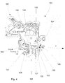
- the Figures 2 to 4 disclose a circuit breaker 100 according to the invention comprising a subassembly 123 comprising an opening and closing mechanism 160 having at least two stable states, a first state for which an upstream electrical line is not electrically connected to a downstream line (open contact) and a second state for which the upstream power line is electrically connected to the downstream line (closed contact).
- Said subassembly 123 also comprises a driver 120 and an actuator 150, preferably a thermal actuator, adapted to return the opening and closing mechanism 160 to the first state when a product connected to the downstream electrical line is traversed by a higher current. the rated current for which the product is intended (current overload).
- Said circuit breaker 100 comprises a trigger 140 able to swing the opening and closing mechanism 160 from the second state to the first state when the trigger 140 is moved, relative to the opening and closing mechanism 160, to bring the mechanism of opening and closing 160 to the first state.
- subassembly 123 comprises guide means 124 of the trainer.
- the driver 120 has a general U shape, the first leg 125 of the U being connected to the trigger 140 and the second leg 126 of the U being connected to the actuator 150, the middle portion 127 of the connecting U the two branches 125, 126 of the U.
- circuit breaker 100 can gain in compactness (and therefore in margin of adjustment of the thermal protection).
- the driver 120 can be, on the one hand, connected to the actuator 150 and, on the other hand, connected to the trigger 140.
- the driver 120 is made of metal material, preferably from a wire.
- the section of this wire may be round or square.
- the wire has the advantage of being easily achievable and rigid by using a wire of small diameter (compared to a plastic part).
- the driver 120 is guided on the envelopes 121, 122.
- the envelopes 121, 122 can hold the various parts of the lock (subassembly 123) (including thermal) and in particular the driver 120 in the guide means 124.
- the various parts of the lock can be held by deformable clips 128 or by an additional piece to be fixed on the envelopes 121, 122 or at least one clipping pin.
- the subset 123 is complete and autonomous.
- the subassembly 123 comprises at least one holding shell which can be made by at least one of the envelope pieces 121, 122, preferably the two envelope pieces 121, 122.
- the driver 120 operates in translation and has no rigid connection with the trigger 140, which reduces its bulk during operation.
- the driver 120 is free and has no relative movement relative to the fixed parts of the product during the movement of the mechanism (opening or closing contacts).
- the driver 120 can be guided in translation in the guide means 124 in a translation direction T.
- the trigger 140 may be provided with an orifice 141 in which the driver 120 is arranged.
- the first leg 125 of the U of the generally U-shaped driver is arranged in the orifice 141.
- the actuator 150 is capable of returning the opening and closing mechanism 160 from the second state to the first state by bearing against the driver 120 when a product connected to the downstream electrical line is traversed by a current greater than the current. nominal.
- the actuator may be able to return the opening and closing mechanism 160 from the second state to the first state by bearing against the second leg 126 of the U of the U-shaped driver 120 when the product connected to the line downstream electrical current is traversed by a current greater than the rated current.
- the driver may abut against a border 142 of the orifice 141 when the opening and closing mechanism 160 is in its second state to tilt the opening and closing mechanism 160 from the second state to the first state.
- the first leg 125 of the U of the generally U-shaped driver 120 can bear against the edge 142 of the orifice 141 when the opening and closing mechanism 160 is in its second state to tilt the opening and closing mechanism 160 from the second state to the first state.
- the orifice 141 may have a substantially oblong and curvilinear shape.
- the orifice has essentially a form of beans and / or bananas and / or C.
- the figures 3 and 4 show the coach 120 taking a position called neutral position.
- the opening and closing mechanism 160 can be designed to be able to freely switch from the first state to the second state and vice versa.
- the orifice 141 is designed to allow the opening and closing mechanism 160 to swing from the first state to the second state and vice versa, when the driver 120 assumes a neutral position.
- the driver 120 may also take an actuating position (not disclosed in the figures) which is offset from the neutral position in the translation direction T.
- a tilting of the opening and closing mechanism 160 from the first state to the second state causes a displacement of the driver 120 from the actuating position to the position neutral.
- the driver 120 can be clipped into the envelope parts 121, 122, which eliminates the assembly difficulties for this type of subassembly 123 (a mechanism with two contacts and a translation drive with a stack assembly ).
- the coach 120 can also be maintained in the envelope pieces 121, 122 by an additional piece which would itself be fixed on the envelopes 121, 122.
- the driver 120 can be assembled by simple clipping after forming the complete subset 123, thus the complete subassembly 123 is functional and can be tested in a template before assembly of the complete product, therefore independently of the complete product. This feature can not be achieved in the case where the driver 120 is guided by the envelope parts 121, 122 of the product for example.
- the deformable clips extend in a direction substantially perpendicular to the direction of translation.
- the trigger 140 is pivotally mounted relative to at least one envelope piece 121, 122 around a pivot axis.
- the circuit breaker that is the subject of the application has the advantage of saving space for future developments more and more compact, as well as having a complete and independent mechanical subassembly with the 120 trainer already assembled on it, or to to assemble in the final environment without the constraint of a necessary maintenance in the envelopes (in the case of a stack assembly).
Landscapes
- Breakers (AREA)
- Arc-Extinguishing Devices That Are Switches (AREA)
- Emergency Protection Circuit Devices (AREA)
Applications Claiming Priority (1)
| Application Number | Priority Date | Filing Date | Title |
|---|---|---|---|
| FR1461738A FR3029350B1 (fr) | 2014-12-01 | 2014-12-01 | Dispositif de protection differentielle |
Publications (2)
| Publication Number | Publication Date |
|---|---|
| EP3029703A1 true EP3029703A1 (de) | 2016-06-08 |
| EP3029703B1 EP3029703B1 (de) | 2018-01-31 |
Family
ID=52589548
Family Applications (5)
| Application Number | Title | Priority Date | Filing Date |
|---|---|---|---|
| EP15306902.6A Active EP3029703B1 (de) | 2014-12-01 | 2015-12-01 | Schutzschalter, bevorzugt fehlerstromschutzschalter |
| EP15820215.0A Active EP3227901B1 (de) | 2014-12-01 | 2015-12-01 | Differenzialschutzvorrichtung |
| EP15306904.2A Active EP3029705B1 (de) | 2014-12-01 | 2015-12-01 | Herstellungsverfahren eines elektrischen geräts, das mindestens zwei elektrische funktionen sicherstellt |
| EP15306905.9A Active EP3029706B1 (de) | 2014-12-01 | 2015-12-01 | Unterbrechungsvorrichtung und modularer fehlerstromschutzschalter, der mindestens eine solche unterbrechungsvorrichtung umfasst |
| EP15306903.4A Active EP3029704B1 (de) | 2014-12-01 | 2015-12-01 | Fehlerstromschutzschalter |
Family Applications After (4)
| Application Number | Title | Priority Date | Filing Date |
|---|---|---|---|
| EP15820215.0A Active EP3227901B1 (de) | 2014-12-01 | 2015-12-01 | Differenzialschutzvorrichtung |
| EP15306904.2A Active EP3029705B1 (de) | 2014-12-01 | 2015-12-01 | Herstellungsverfahren eines elektrischen geräts, das mindestens zwei elektrische funktionen sicherstellt |
| EP15306905.9A Active EP3029706B1 (de) | 2014-12-01 | 2015-12-01 | Unterbrechungsvorrichtung und modularer fehlerstromschutzschalter, der mindestens eine solche unterbrechungsvorrichtung umfasst |
| EP15306903.4A Active EP3029704B1 (de) | 2014-12-01 | 2015-12-01 | Fehlerstromschutzschalter |
Country Status (4)
| Country | Link |
|---|---|
| EP (5) | EP3029703B1 (de) |
| AU (1) | AU2015356923B2 (de) |
| FR (1) | FR3029350B1 (de) |
| WO (1) | WO2016087768A1 (de) |
Citations (5)
| Publication number | Priority date | Publication date | Assignee | Title |
|---|---|---|---|---|
| CH604363A5 (en) * | 1976-09-10 | 1978-09-15 | Landis & Gyr Ag | Electrical cut=out relay |
| EP0338930A1 (de) * | 1988-04-22 | 1989-10-25 | Hager Electro S.A. | Lastschalter oder Differential-Lastschalter |
| FR2661776A1 (fr) | 1990-05-04 | 1991-11-08 | Merlin Gerin | Declencheur instantane d'un disjoncteur. |
| EP0295158B1 (de) | 1987-06-09 | 1992-07-22 | Merlin Gerin | Steuermechanismus eines elektrischen Kleinschalters |
| FR2686453A1 (fr) * | 1992-01-17 | 1993-07-23 | Legrand Sa | Interrupteur differentiel. |
Family Cites Families (13)
| Publication number | Priority date | Publication date | Assignee | Title |
|---|---|---|---|---|
| FR2378344A1 (fr) * | 1977-01-25 | 1978-08-18 | Telemecanique Electrique | Piece de soufflage |
| AT384120B (de) * | 1985-12-02 | 1987-10-12 | Felten & Guilleaume Ag Oester | Fehlerstrom- und leitungsschutzschalter |
| FR2663153B1 (fr) * | 1990-06-07 | 1992-09-11 | Legrand Sa | Dispositif de declenchement differentiel. |
| FR2701335B1 (fr) * | 1993-02-09 | 1995-04-14 | Merlin Gerin | Bloc de protection différentielle avec sous ensemble fonctionnel testable. |
| US5920451A (en) * | 1997-09-05 | 1999-07-06 | Carlingswitch, Inc. | Earth leakage circuit breaker assembly |
| FR2777110B1 (fr) | 1998-04-03 | 2000-06-23 | Legrand Sa | Disjoncteur differentiel multipolaire |
| FR2811805B1 (fr) * | 2000-07-13 | 2002-08-30 | Schneider Electric Ind Sa | Appareil de protection electrique differentiel |
| FR2828329B1 (fr) * | 2001-07-31 | 2003-12-12 | Legrand Sa | Dispositif pour l'extinction d'un arc electrique |
| DE10230094B4 (de) * | 2002-07-04 | 2004-06-24 | Siemens Ag | Lichtbogen-Löschvorrichtung |
| FR2865582B1 (fr) * | 2004-01-22 | 2006-03-10 | Schneider Electric Ind Sas | Dispositif de protection differentielle avec moyens de reglage simplifies des parametres de protection |
| AT509838A2 (de) * | 2010-03-19 | 2011-11-15 | Moeller Gebaeudeautomation Gmbh | Fehlerstromschutzschalter |
| CN103380476B (zh) * | 2011-02-16 | 2016-05-25 | 伊顿工业(奥地利)有限公司 | 故障电流保护开关 |
| DE102012111615A1 (de) * | 2012-11-29 | 2014-06-05 | Eaton Industries (Austria) Gmbh | Fehlerstromschutzschalter |
-
2014
- 2014-12-01 FR FR1461738A patent/FR3029350B1/fr not_active Expired - Fee Related
-
2015
- 2015-12-01 EP EP15306902.6A patent/EP3029703B1/de active Active
- 2015-12-01 EP EP15820215.0A patent/EP3227901B1/de active Active
- 2015-12-01 AU AU2015356923A patent/AU2015356923B2/en active Active
- 2015-12-01 EP EP15306904.2A patent/EP3029705B1/de active Active
- 2015-12-01 EP EP15306905.9A patent/EP3029706B1/de active Active
- 2015-12-01 WO PCT/FR2015/053280 patent/WO2016087768A1/fr not_active Ceased
- 2015-12-01 EP EP15306903.4A patent/EP3029704B1/de active Active
Patent Citations (5)
| Publication number | Priority date | Publication date | Assignee | Title |
|---|---|---|---|---|
| CH604363A5 (en) * | 1976-09-10 | 1978-09-15 | Landis & Gyr Ag | Electrical cut=out relay |
| EP0295158B1 (de) | 1987-06-09 | 1992-07-22 | Merlin Gerin | Steuermechanismus eines elektrischen Kleinschalters |
| EP0338930A1 (de) * | 1988-04-22 | 1989-10-25 | Hager Electro S.A. | Lastschalter oder Differential-Lastschalter |
| FR2661776A1 (fr) | 1990-05-04 | 1991-11-08 | Merlin Gerin | Declencheur instantane d'un disjoncteur. |
| FR2686453A1 (fr) * | 1992-01-17 | 1993-07-23 | Legrand Sa | Interrupteur differentiel. |
Also Published As
| Publication number | Publication date |
|---|---|
| WO2016087768A1 (fr) | 2016-06-09 |
| EP3029705B1 (de) | 2020-11-04 |
| FR3029350A1 (fr) | 2016-06-03 |
| EP3029706B1 (de) | 2020-11-04 |
| AU2015356923A1 (en) | 2017-07-20 |
| EP3227901A1 (de) | 2017-10-11 |
| EP3227901B1 (de) | 2019-07-10 |
| EP3029706A1 (de) | 2016-06-08 |
| AU2015356923B2 (en) | 2020-03-12 |
| EP3029704B1 (de) | 2021-03-31 |
| FR3029350B1 (fr) | 2016-12-23 |
| EP3029705A1 (de) | 2016-06-08 |
| EP3029703B1 (de) | 2018-01-31 |
| EP3029704A1 (de) | 2016-06-08 |
Similar Documents
| Publication | Publication Date | Title |
|---|---|---|
| EP1975971B1 (de) | Bedienungsvorrichtung eines elektrischen Sicherungsgeräts und elektrisches Sicherungsgerät, das sie umfasst | |
| EP2466601B1 (de) | Unterbrechungsvorrichtung mit Monitor mit Lichtbogenunterbrechung | |
| EP2061059B1 (de) | Steuervorrichtung für ein elektrisches Unterbrechungsgerät und elektrisches Unterbrechungsgerät, das damit ausgestattet ist | |
| EP2460172B1 (de) | Drehbares steuersystem für einen stromschutzschalter | |
| EP0570647B1 (de) | Schaltschloss für Schutzschalter und Schutzschalter, mit diesem integriert | |
| EP0161120B1 (de) | Anordnung zur Lastunterbrechung und sichtbaren Trennung eines elektrischen Stromkreises | |
| EP2061058B1 (de) | Steuervorrichtung für ein elektrisches Unterbrechungsgerät und elektrisches Unterbrechungsgerät, das damit ausgestattet ist | |
| FR3029009A1 (fr) | Systeme de commande a declenchement pour pole de coupure et appareil de coupure | |
| EP1965405B1 (de) | Versetzte Betätigungsvorrichtung für einen Schalter einschließlich einer Hilfsvorrichtung zur Auslösung | |
| FR2806521A1 (fr) | Mecanisme d'actionnement de disjoncteur et disjoncteur comportant un tel mecanisme | |
| EP2365510B1 (de) | Leistungsschalter | |
| EP2377139B1 (de) | Vorrichtung zur fernbetätigung und damit versehener schutzschalter | |
| EP2717284B1 (de) | Bedienungsvorrichtung eines elektrischen Schutzschaltgeräts, und diese umfassendes elektrisches Schutzschaltgerät | |
| EP1274109B1 (de) | Betätigungsmechanismus für einen Lastschalter | |
| EP3029703B1 (de) | Schutzschalter, bevorzugt fehlerstromschutzschalter | |
| EP0569651B1 (de) | Montageverfahren für Phasen-Neutralleiter-Schutzschalter und Schutzschalter dieser Bauart | |
| FR2887071A1 (fr) | Dispositif d'actionnement d'un appareil electrique interrupteur a moyens de blocage en rotation. | |
| WO2010109129A1 (fr) | Déclencheur magnétothermique | |
| FR2538947A1 (fr) | Interrupteur a fermeture et ouverture commandees et a ouverture automatique en cas de surcharge de courant | |
| EP0218497B1 (de) | Schutzschalter mit federnder Lasche | |
| EP2565890B1 (de) | Elektrisches Stromunterbrechungsgerät mit hoher Verschlusskraft | |
| EP2237302B1 (de) | Vorrichtung zur thermischen Auslösung für elektrisches Schutzgerät | |
| EP2359379B1 (de) | Steuermechanismus für eine fernbediente abschneideeinrichtung, abschneideeinrichtung und fernbediente unterbrecherschaltung mit einem solchen mechanismus | |
| EP3134910B1 (de) | Vorrichtung mit beweglichem kontakt ohne leitfähige litze | |
| EP3091557A1 (de) | Bedienungsvorrichtung eines elektrischen sicherungsgeräts, und diese umfassendes elektrisches sicherungsgerät |
Legal Events
| Date | Code | Title | Description |
|---|---|---|---|
| PUAI | Public reference made under article 153(3) epc to a published international application that has entered the european phase |
Free format text: ORIGINAL CODE: 0009012 |
|
| AK | Designated contracting states |
Kind code of ref document: A1 Designated state(s): AL AT BE BG CH CY CZ DE DK EE ES FI FR GB GR HR HU IE IS IT LI LT LU LV MC MK MT NL NO PL PT RO RS SE SI SK SM TR |
|
| AX | Request for extension of the european patent |
Extension state: BA ME |
|
| 17P | Request for examination filed |
Effective date: 20161208 |
|
| RBV | Designated contracting states (corrected) |
Designated state(s): AL AT BE BG CH CY CZ DE DK EE ES FI FR GB GR HR HU IE IS IT LI LT LU LV MC MK MT NL NO PL PT RO RS SE SI SK SM TR |
|
| RIC1 | Information provided on ipc code assigned before grant |
Ipc: H01H 71/02 20060101ALI20170602BHEP Ipc: H02H 3/33 20060101ALI20170602BHEP Ipc: H01H 83/22 20060101AFI20170602BHEP |
|
| GRAP | Despatch of communication of intention to grant a patent |
Free format text: ORIGINAL CODE: EPIDOSNIGR1 |
|
| INTG | Intention to grant announced |
Effective date: 20170719 |
|
| GRAS | Grant fee paid |
Free format text: ORIGINAL CODE: EPIDOSNIGR3 |
|
| GRAA | (expected) grant |
Free format text: ORIGINAL CODE: 0009210 |
|
| AK | Designated contracting states |
Kind code of ref document: B1 Designated state(s): AL AT BE BG CH CY CZ DE DK EE ES FI FR GB GR HR HU IE IS IT LI LT LU LV MC MK MT NL NO PL PT RO RS SE SI SK SM TR |
|
| REG | Reference to a national code |
Ref country code: GB Ref legal event code: FG4D Free format text: NOT ENGLISH Ref country code: CH Ref legal event code: EP |
|
| REG | Reference to a national code |
Ref country code: AT Ref legal event code: REF Ref document number: 968067 Country of ref document: AT Kind code of ref document: T Effective date: 20180215 |
|
| REG | Reference to a national code |
Ref country code: IE Ref legal event code: FG4D Free format text: LANGUAGE OF EP DOCUMENT: FRENCH |
|
| REG | Reference to a national code |
Ref country code: DE Ref legal event code: R096 Ref document number: 602015007785 Country of ref document: DE |
|
| GRAT | Correction requested after decision to grant or after decision to maintain patent in amended form |
Free format text: ORIGINAL CODE: EPIDOSNCDEC |
|
| REG | Reference to a national code |
Ref country code: CH Ref legal event code: NV Representative=s name: DR. GRAF AND PARTNER AG INTELLECTUAL PROPERTY, CH |
|
| RAP2 | Party data changed (patent owner data changed or rights of a patent transferred) |
Owner name: HAGER-ELECTRO SAS (SOCIETE PAR ACTIONS SIMPLIFIEE) |
|
| REG | Reference to a national code |
Ref country code: CH Ref legal event code: PCOW Free format text: NEW ADDRESS: 132, BOULEVARD D'EUROPE, 67210 OBERNAI (FR) |
|
| REG | Reference to a national code |
Ref country code: NL Ref legal event code: MP Effective date: 20180131 |
|
| REG | Reference to a national code |
Ref country code: LT Ref legal event code: MG4D |
|
| REG | Reference to a national code |
Ref country code: AT Ref legal event code: MK05 Ref document number: 968067 Country of ref document: AT Kind code of ref document: T Effective date: 20180131 |
|
| RAP2 | Party data changed (patent owner data changed or rights of a patent transferred) |
Owner name: HAGER-ELECTRO SAS |
|
| PG25 | Lapsed in a contracting state [announced via postgrant information from national office to epo] |
Ref country code: HR Free format text: LAPSE BECAUSE OF FAILURE TO SUBMIT A TRANSLATION OF THE DESCRIPTION OR TO PAY THE FEE WITHIN THE PRESCRIBED TIME-LIMIT Effective date: 20180131 Ref country code: LT Free format text: LAPSE BECAUSE OF FAILURE TO SUBMIT A TRANSLATION OF THE DESCRIPTION OR TO PAY THE FEE WITHIN THE PRESCRIBED TIME-LIMIT Effective date: 20180131 Ref country code: FI Free format text: LAPSE BECAUSE OF FAILURE TO SUBMIT A TRANSLATION OF THE DESCRIPTION OR TO PAY THE FEE WITHIN THE PRESCRIBED TIME-LIMIT Effective date: 20180131 Ref country code: NO Free format text: LAPSE BECAUSE OF FAILURE TO SUBMIT A TRANSLATION OF THE DESCRIPTION OR TO PAY THE FEE WITHIN THE PRESCRIBED TIME-LIMIT Effective date: 20180430 Ref country code: ES Free format text: LAPSE BECAUSE OF FAILURE TO SUBMIT A TRANSLATION OF THE DESCRIPTION OR TO PAY THE FEE WITHIN THE PRESCRIBED TIME-LIMIT Effective date: 20180131 Ref country code: NL Free format text: LAPSE BECAUSE OF FAILURE TO SUBMIT A TRANSLATION OF THE DESCRIPTION OR TO PAY THE FEE WITHIN THE PRESCRIBED TIME-LIMIT Effective date: 20180131 |
|
| PG25 | Lapsed in a contracting state [announced via postgrant information from national office to epo] |
Ref country code: AT Free format text: LAPSE BECAUSE OF FAILURE TO SUBMIT A TRANSLATION OF THE DESCRIPTION OR TO PAY THE FEE WITHIN THE PRESCRIBED TIME-LIMIT Effective date: 20180131 Ref country code: RS Free format text: LAPSE BECAUSE OF FAILURE TO SUBMIT A TRANSLATION OF THE DESCRIPTION OR TO PAY THE FEE WITHIN THE PRESCRIBED TIME-LIMIT Effective date: 20180131 Ref country code: SE Free format text: LAPSE BECAUSE OF FAILURE TO SUBMIT A TRANSLATION OF THE DESCRIPTION OR TO PAY THE FEE WITHIN THE PRESCRIBED TIME-LIMIT Effective date: 20180131 Ref country code: LV Free format text: LAPSE BECAUSE OF FAILURE TO SUBMIT A TRANSLATION OF THE DESCRIPTION OR TO PAY THE FEE WITHIN THE PRESCRIBED TIME-LIMIT Effective date: 20180131 Ref country code: PL Free format text: LAPSE BECAUSE OF FAILURE TO SUBMIT A TRANSLATION OF THE DESCRIPTION OR TO PAY THE FEE WITHIN THE PRESCRIBED TIME-LIMIT Effective date: 20180131 Ref country code: BG Free format text: LAPSE BECAUSE OF FAILURE TO SUBMIT A TRANSLATION OF THE DESCRIPTION OR TO PAY THE FEE WITHIN THE PRESCRIBED TIME-LIMIT Effective date: 20180430 Ref country code: IS Free format text: LAPSE BECAUSE OF FAILURE TO SUBMIT A TRANSLATION OF THE DESCRIPTION OR TO PAY THE FEE WITHIN THE PRESCRIBED TIME-LIMIT Effective date: 20180531 Ref country code: GR Free format text: LAPSE BECAUSE OF FAILURE TO SUBMIT A TRANSLATION OF THE DESCRIPTION OR TO PAY THE FEE WITHIN THE PRESCRIBED TIME-LIMIT Effective date: 20180501 |
|
| PG25 | Lapsed in a contracting state [announced via postgrant information from national office to epo] |
Ref country code: MT Free format text: LAPSE BECAUSE OF FAILURE TO SUBMIT A TRANSLATION OF THE DESCRIPTION OR TO PAY THE FEE WITHIN THE PRESCRIBED TIME-LIMIT Effective date: 20180131 |
|
| PG25 | Lapsed in a contracting state [announced via postgrant information from national office to epo] |
Ref country code: AL Free format text: LAPSE BECAUSE OF FAILURE TO SUBMIT A TRANSLATION OF THE DESCRIPTION OR TO PAY THE FEE WITHIN THE PRESCRIBED TIME-LIMIT Effective date: 20180131 Ref country code: EE Free format text: LAPSE BECAUSE OF FAILURE TO SUBMIT A TRANSLATION OF THE DESCRIPTION OR TO PAY THE FEE WITHIN THE PRESCRIBED TIME-LIMIT Effective date: 20180131 Ref country code: RO Free format text: LAPSE BECAUSE OF FAILURE TO SUBMIT A TRANSLATION OF THE DESCRIPTION OR TO PAY THE FEE WITHIN THE PRESCRIBED TIME-LIMIT Effective date: 20180131 |
|
| REG | Reference to a national code |
Ref country code: DE Ref legal event code: R097 Ref document number: 602015007785 Country of ref document: DE |
|
| PG25 | Lapsed in a contracting state [announced via postgrant information from national office to epo] |
Ref country code: SK Free format text: LAPSE BECAUSE OF FAILURE TO SUBMIT A TRANSLATION OF THE DESCRIPTION OR TO PAY THE FEE WITHIN THE PRESCRIBED TIME-LIMIT Effective date: 20180131 Ref country code: CZ Free format text: LAPSE BECAUSE OF FAILURE TO SUBMIT A TRANSLATION OF THE DESCRIPTION OR TO PAY THE FEE WITHIN THE PRESCRIBED TIME-LIMIT Effective date: 20180131 Ref country code: DK Free format text: LAPSE BECAUSE OF FAILURE TO SUBMIT A TRANSLATION OF THE DESCRIPTION OR TO PAY THE FEE WITHIN THE PRESCRIBED TIME-LIMIT Effective date: 20180131 Ref country code: SM Free format text: LAPSE BECAUSE OF FAILURE TO SUBMIT A TRANSLATION OF THE DESCRIPTION OR TO PAY THE FEE WITHIN THE PRESCRIBED TIME-LIMIT Effective date: 20180131 |
|
| PLBE | No opposition filed within time limit |
Free format text: ORIGINAL CODE: 0009261 |
|
| STAA | Information on the status of an ep patent application or granted ep patent |
Free format text: STATUS: NO OPPOSITION FILED WITHIN TIME LIMIT |
|
| 26N | No opposition filed |
Effective date: 20181102 |
|
| PG25 | Lapsed in a contracting state [announced via postgrant information from national office to epo] |
Ref country code: SI Free format text: LAPSE BECAUSE OF FAILURE TO SUBMIT A TRANSLATION OF THE DESCRIPTION OR TO PAY THE FEE WITHIN THE PRESCRIBED TIME-LIMIT Effective date: 20180131 |
|
| PG25 | Lapsed in a contracting state [announced via postgrant information from national office to epo] |
Ref country code: LU Free format text: LAPSE BECAUSE OF NON-PAYMENT OF DUE FEES Effective date: 20181201 Ref country code: MC Free format text: LAPSE BECAUSE OF FAILURE TO SUBMIT A TRANSLATION OF THE DESCRIPTION OR TO PAY THE FEE WITHIN THE PRESCRIBED TIME-LIMIT Effective date: 20180131 |
|
| REG | Reference to a national code |
Ref country code: IE Ref legal event code: MM4A |
|
| REG | Reference to a national code |
Ref country code: BE Ref legal event code: MM Effective date: 20181231 |
|
| PG25 | Lapsed in a contracting state [announced via postgrant information from national office to epo] |
Ref country code: IE Free format text: LAPSE BECAUSE OF NON-PAYMENT OF DUE FEES Effective date: 20181201 |
|
| PG25 | Lapsed in a contracting state [announced via postgrant information from national office to epo] |
Ref country code: BE Free format text: LAPSE BECAUSE OF NON-PAYMENT OF DUE FEES Effective date: 20181231 |
|
| PG25 | Lapsed in a contracting state [announced via postgrant information from national office to epo] |
Ref country code: TR Free format text: LAPSE BECAUSE OF FAILURE TO SUBMIT A TRANSLATION OF THE DESCRIPTION OR TO PAY THE FEE WITHIN THE PRESCRIBED TIME-LIMIT Effective date: 20180131 |
|
| PG25 | Lapsed in a contracting state [announced via postgrant information from national office to epo] |
Ref country code: PT Free format text: LAPSE BECAUSE OF FAILURE TO SUBMIT A TRANSLATION OF THE DESCRIPTION OR TO PAY THE FEE WITHIN THE PRESCRIBED TIME-LIMIT Effective date: 20180131 |
|
| PG25 | Lapsed in a contracting state [announced via postgrant information from national office to epo] |
Ref country code: MK Free format text: LAPSE BECAUSE OF NON-PAYMENT OF DUE FEES Effective date: 20180131 Ref country code: HU Free format text: LAPSE BECAUSE OF FAILURE TO SUBMIT A TRANSLATION OF THE DESCRIPTION OR TO PAY THE FEE WITHIN THE PRESCRIBED TIME-LIMIT; INVALID AB INITIO Effective date: 20151201 Ref country code: CY Free format text: LAPSE BECAUSE OF FAILURE TO SUBMIT A TRANSLATION OF THE DESCRIPTION OR TO PAY THE FEE WITHIN THE PRESCRIBED TIME-LIMIT Effective date: 20180131 |
|
| GBPC | Gb: european patent ceased through non-payment of renewal fee |
Effective date: 20191201 |
|
| PG25 | Lapsed in a contracting state [announced via postgrant information from national office to epo] |
Ref country code: GB Free format text: LAPSE BECAUSE OF NON-PAYMENT OF DUE FEES Effective date: 20191201 |
|
| P01 | Opt-out of the competence of the unified patent court (upc) registered |
Effective date: 20230606 |
|
| REG | Reference to a national code |
Ref country code: CH Ref legal event code: U11 Free format text: ST27 STATUS EVENT CODE: U-0-0-U10-U11 (AS PROVIDED BY THE NATIONAL OFFICE) Effective date: 20260101 |
|
| PGFP | Annual fee paid to national office [announced via postgrant information from national office to epo] |
Ref country code: IT Payment date: 20251219 Year of fee payment: 11 |
|
| PGFP | Annual fee paid to national office [announced via postgrant information from national office to epo] |
Ref country code: FR Payment date: 20251226 Year of fee payment: 11 |
|
| PGFP | Annual fee paid to national office [announced via postgrant information from national office to epo] |
Ref country code: DE Payment date: 20251229 Year of fee payment: 11 |
|
| PGFP | Annual fee paid to national office [announced via postgrant information from national office to epo] |
Ref country code: CH Payment date: 20260101 Year of fee payment: 11 |