EP3029809A2 - Motif d'enroulement de stator pour moteur d'entraînement en épingle à cheveux - Google Patents
Motif d'enroulement de stator pour moteur d'entraînement en épingle à cheveux Download PDFInfo
- Publication number
- EP3029809A2 EP3029809A2 EP15188648.8A EP15188648A EP3029809A2 EP 3029809 A2 EP3029809 A2 EP 3029809A2 EP 15188648 A EP15188648 A EP 15188648A EP 3029809 A2 EP3029809 A2 EP 3029809A2
- Authority
- EP
- European Patent Office
- Prior art keywords
- draw out
- slot
- out part
- layer
- neutral point
- Prior art date
- Legal status (The legal status is an assumption and is not a legal conclusion. Google has not performed a legal analysis and makes no representation as to the accuracy of the status listed.)
- Withdrawn
Links
- 238000004804 winding Methods 0.000 title claims abstract description 81
- 239000011295 pitch Substances 0.000 claims abstract description 98
- 230000007935 neutral effect Effects 0.000 claims description 105
- 230000000052 comparative effect Effects 0.000 description 12
- 238000009413 insulation Methods 0.000 description 8
- 238000010586 diagram Methods 0.000 description 5
- 238000000034 method Methods 0.000 description 4
- 230000002093 peripheral effect Effects 0.000 description 3
- RYGMFSIKBFXOCR-UHFFFAOYSA-N Copper Chemical compound [Cu] RYGMFSIKBFXOCR-UHFFFAOYSA-N 0.000 description 2
- 239000011248 coating agent Substances 0.000 description 2
- 238000000576 coating method Methods 0.000 description 2
- 229910052802 copper Inorganic materials 0.000 description 2
- 239000010949 copper Substances 0.000 description 2
- 230000000694 effects Effects 0.000 description 2
- 230000004907 flux Effects 0.000 description 2
- 239000000446 fuel Substances 0.000 description 2
- 230000001360 synchronised effect Effects 0.000 description 2
- 229910000831 Steel Inorganic materials 0.000 description 1
- 230000015556 catabolic process Effects 0.000 description 1
- 239000000470 constituent Substances 0.000 description 1
- 230000007717 exclusion Effects 0.000 description 1
- 238000003780 insertion Methods 0.000 description 1
- 230000037431 insertion Effects 0.000 description 1
- 238000012986 modification Methods 0.000 description 1
- 230000004048 modification Effects 0.000 description 1
- 238000000465 moulding Methods 0.000 description 1
- 239000003208 petroleum Substances 0.000 description 1
- 239000010959 steel Substances 0.000 description 1
- 238000003466 welding Methods 0.000 description 1
Images


Classifications
-
- H—ELECTRICITY
- H02—GENERATION; CONVERSION OR DISTRIBUTION OF ELECTRIC POWER
- H02K—DYNAMO-ELECTRIC MACHINES
- H02K3/00—Details of windings
- H02K3/46—Fastening of windings on the stator or rotor structure
- H02K3/48—Fastening of windings on the stator or rotor structure in slots
-
- H—ELECTRICITY
- H02—GENERATION; CONVERSION OR DISTRIBUTION OF ELECTRIC POWER
- H02K—DYNAMO-ELECTRIC MACHINES
- H02K3/00—Details of windings
- H02K3/04—Windings characterised by the conductor shape, form or construction, e.g. with bar conductors
- H02K3/12—Windings characterised by the conductor shape, form or construction, e.g. with bar conductors arranged in slots
-
- H—ELECTRICITY
- H02—GENERATION; CONVERSION OR DISTRIBUTION OF ELECTRIC POWER
- H02K—DYNAMO-ELECTRIC MACHINES
- H02K3/00—Details of windings
- H02K3/04—Windings characterised by the conductor shape, form or construction, e.g. with bar conductors
- H02K3/28—Layout of windings or of connections between windings
-
- Y—GENERAL TAGGING OF NEW TECHNOLOGICAL DEVELOPMENTS; GENERAL TAGGING OF CROSS-SECTIONAL TECHNOLOGIES SPANNING OVER SEVERAL SECTIONS OF THE IPC; TECHNICAL SUBJECTS COVERED BY FORMER USPC CROSS-REFERENCE ART COLLECTIONS [XRACs] AND DIGESTS
- Y10—TECHNICAL SUBJECTS COVERED BY FORMER USPC
- Y10S—TECHNICAL SUBJECTS COVERED BY FORMER USPC CROSS-REFERENCE ART COLLECTIONS [XRACs] AND DIGESTS
- Y10S174/00—Electricity: conductors and insulators
- Y10S174/13—High voltage cable, e.g. above 10kv, corona prevention
- Y10S174/14—High voltage cable, e.g. above 10kv, corona prevention having a particular cable application, e.g. winding
- Y10S174/19—High voltage cable, e.g. above 10kv, corona prevention having a particular cable application, e.g. winding in a dynamo-electric machine
- Y10S174/20—Stator
Definitions
- Embodiments of the present disclosure relate generally to a drive motor for an environmentally friendly vehicle, and more particularly, to a stator winding pattern of a hairpin drive motor capable of minimizing a maximum potential difference at an adjacent section between phases in a hairpin drive motor.
- environmentally friendly vehicles such as a hybrid vehicle or an electric vehicle
- a hybrid vehicle can run in an electric vehicle (EV) mode (i.e., a pure electric mode) using only power of a drive motor or a hybrid electric vehicle (HEV) mode using driving torques of both an engine and a drive motor for power. Meanwhile, an electric vehicle runs using solely the torque of the drive motor for power.
- EV electric vehicle
- HEV hybrid electric vehicle
- a drive motor used as a power source for an environmentally friendly vehicle is generally a permanent magnet synchronous motor (PMSM).
- the drive motor as a PMSM typically includes a stator to generate a magnetic flux, a rotor spaced apart from the stator by a predetermined gap, and a permanent magnet installed at the rotor.
- the stator includes a plurality of slots which are formed at an inner peripheral portion of a stator core, and a stator coil is wound in the slots. Accordingly, if an AC current is applied to a stator coil, the stator generates a rotation magnetic field so that a rotation torque may be generated in the stator due to the rotation magnetic field.
- the drive motor is classified into a distribution winding drive motor and a concentrated winding drive motor depending on a winding scheme of the stator coil.
- a stator of the distribution winding drive motor is divided into a segment coil stator and a distribution winding coil stator according to a winding scheme of the coil.
- the segment coil stator is a stator for inserting a coil in a slot of a stator core after primarily molding the coil to have a predetermined shape in advance.
- the distribution winding coil stator inserts a coil assembly in a slot of the stator core.
- Output of the drive motor is proportional to the number of turns of a coil wound in the stator core.
- the number of turns of the coil is increased, the size of the stator core or the motor is inevitably increased which results in reduction in miniaturization.
- a method of increasing a space factor of a coil wound around the stator core e.g., by minimizing a dead space between the stator core and a winding coil may be considered.
- a method of using a flat coil (i.e., a "flat wire") having a square section has been actively studied.
- the flat coil may reduce the dead space and improve the space factor due to a shape of a section as compared with the ring-shaped coil.
- the flat coil has a difficulty in coil winding work as compared to the ring-shaped coil. This is because the flat coil is manufactured to have a wide cross-section as compared with the ring shaped coil in order to maximize the space factor so it is difficult to use a winding machine.
- a motor including a coil winding formed in this way is conventionally referred to as a "hairpin drive motor.”
- the coil winding structure of the hairpin drive motor overcomes a device limit due to a winding machine and coil winding work is easily possible in a case of the flat coil and may implement a miniaturized motor with high power by increasing the space factor of the coil.
- the hairpin drive motor described above is configured with a continuous winding by inserting a leg of the hairpin in a slot of the stator core and welding an adjacent leg in a radial direction in the slot, a section adjacent to a hairpin on a different phase is generated. Insulation is weak in the above section so that there is a need for a separate insulation structure.
- a rotating direction of the motor and a draw out position of one phase e.g., a U-phase
- a position of a different phase e.g., V-phase or W-phase
- a 3-phase draw out part and a neutral point draw out part may be formed as a pattern of a rule minimizing a pitch between phases in order to simplify a winding structure of a hairpin by reducing a draw out length of the winding coil.
- a conventional 3-phase draw output part has a coil winding structure minimizing a patch between phases, a section adjacent to a hairpin of different phases is generated in an insertion direction of the hairpin inserted into a slot of the stator. Therefore, a section having a maximum potential difference is located in the adjacent section between phases, thereby causing an insulation problem of the motor.
- the present disclosure has been made in an effort to provide a stator winding pattern of a hairpin driver motor having advantages of minimizing increase in draw out lengths of a phase draw out part and a neutral draw out part of one shape while reducing a potential difference of an adjacent section between phases by limiting a winding position of draw out parts having different phases based on a draw out part of one phase.
- Embodiments of the present disclosure provide: a stator winding pattern of a hairpin drive motor including a stator with 8 poles and 48 slots of a distribution winding where a hairpin-type of flat coil is inserted into a slot of a stator core and configured by a full pitch winding implementing 6 pitches of 3 phases and 2 in parallel, the pitch being a distance between adjacent slots, characterized in that: first to fourth layers are formed in the slot of the stator core in a radial direction of the stator core; and when a first layer or a fourth layer is set as a draw out part of one phase in an optional reference slot, a first draw out of a different phase is formed in a draw out slot having 16 pitches in a slot forward direction in a same layer based on the reference slot, and a second draw out of the different phase is formed in a draw out slot having 32 pitches in the slot forward direction in the same layer based on the reference slot.
- neutral draw out parts of three phases may be formed in the first layer by the draw out part of the one phase, a first neutral point draw out part of the different phase may be formed in the draw out slot having 16 pitches in the slot forward direction based on a neutral point draw out part of the one phase, and a second neutral point draw out part of the different phase may be formed in the draw out slot having 32 pitches in the slot forward direction.
- the neutral point draw out parts of the three phases may be formed in the fourth layer by the draw out part of the one phase, the first neutral point draw out part of the different phase may be formed in the draw out slot having 16 pitches in the slot forward direction, and the second neutral point draw out part of the different phase may be formed in the draw out slot having 16 pitches in a slot reverse direction.
- a stator winding pattern of a hairpin drive motor includes a stator with 8 poles and 48 slots of a distribution winding where a hairpin-type flat coil is inserted into a slot of a stator core and configured by a full pitch winding implementing 6 pitches of 3 phases and 2 in parallel (U1, U2/V1, V2/W1, and W2), the 48 slots being referred to as first to 48th slot in a forward direction, characterized in that: first to fourth layers are formed in the slot of the stator core in a radial direction of the stator core; and when a fourth layer of a 16th slot is set as a U1 draw out part, a V1 draw out part is formed in a fourth layer of a 32nd slot, a W1 draw out part is formed in a fourth layer of a 48th slot, a U2 draw out part is formed in a first layer of a 14th slot, a V2 draw out part is formed in a first layer of a 30
- neutral point draw out parts of three phases U1, V1, and W1 may be formed in the first layer by the U1 draw out part, and the U1 neutral point draw out part may be formed in a first layer of an 8th slot, the V1 neutral point draw out part may be formed in a first layer of a 24th slot, and the W1 neutral point draw out part may be formed in a first layer of a 40th slot.
- neutral point draw out parts of the three phases U2, V2, and W2 may be formed in the fourth layer by the U1 draw out part, and the U2 neutral point draw out part may be formed in a fourth layer of a 22nd slot, the V2 neutral point draw out part may be formed in a fourth layer of a 38th lot, and the W2 neutral point draw out part may be formed in a fourth layer of a 6th slot.
- embodiments of the present disclosure may minimize increase in draw out lengths of a draw out part and a neutral draw out part of one shape while reducing a potential difference of an adjacent section between phases by limiting a winding position of draw out parts having different phases based on a draw out part of one phase. Since a maximum potential difference at an adjacent section between phases may be reduced, insulation performance of a drive motor may be ensured without using a separate insulation component between stator coils having different phases. Further, since a coating thickness of a stator coil based on the same capacity of the motor may be reduced, a copper use amount of the stator coil can be reduced, a cost can be reduced, and motor efficiency can be increased.
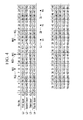
- FIG. 4 is a diagram illustrating a potential difference between phases of a stator winding pattern of a hairpin drive motor in accordance with a comparative example shown in FIG. 3 .
- the terms “first” and “second” will be used to discriminate one component from the other component, but the components may not be limited to the above terms.
- the word “comprise” and variations such as “comprises” or “comprising” will be understood to imply the inclusion of stated elements but not the exclusion of any other elements.
- the suffixes "- unit”, “ ⁇ means”, “- part”, and “- member” mean units of a general configuration that perform at least one function or operation.
- vehicle or “vehicular” or other similar term as used herein is inclusive of motor vehicles in general such as passenger automobiles including sports utility vehicles (SUV), buses, trucks, various commercial vehicles, watercraft including a variety of boats and ships, aircraft, and the like, and includes hybrid vehicles, electric vehicles, plug-in hybrid electric vehicles, hydrogen-powered vehicles and other alternative fuel vehicles (e.g., fuels derived from resources other than petroleum).
- a hybrid vehicle is a vehicle that has two or more sources of power, for example both gasoline-powered and electric-powered vehicles.
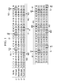
- FIG. 1 is a diagram illustrating a stator winding pattern of a hairpin drive motor in accordance with embodiments of the present disclosure.
- a stator winding pattern of a hairpin drive motor of the present disclosure is applicable to a drive motor for a hybrid vehicle and/or electric vehicle to obtain a driving torque from electrical energy by an environmentally friendly vehicle (e.g., an electric or hybrid vehicle).
- an environmentally friendly vehicle e.g., an electric or hybrid vehicle
- the stator winding pattern of the hairpin drive motor in accordance with the present disclosure is applicable to a permanent magnet synchronous motor (PMSM) as the above drive motor.
- PMSM permanent magnet synchronous motor
- the PMSM includes a stator to generate a magnetic flux, a rotor spaced apart from the stator by a predetermined gap, and a permanent magnet installed at the rotor.
- the stator includes a stator core in which a plurality of steel plates are laminated. A plurality of slots are formed toward a center shaft in the stator core in a radial direction. A stator coil is wound around the slots.
- the stator coil is a hairpin-type of flat coil.
- the stator coil has a pair of legs and has a U-shape or a V-shape.
- the stator coil may include a flat coil having a square section.
- the hairpin type of stator coil is inserted into slots of a stator core, and end portions of a pair of legs protrude outside of the slot.
- the protruded portions of the legs are bent, welded, and electrically connected to each other. That is, a plurality of separated stator coils are inserted and engaged in the slots of the stator core and the stator coils are sequentially welded, and the embodiment is applicable to a hairpin drive motor formed therein with a coil winding of the stator.
- the hairpin drive motor can be applied to a permanent magnet-type of hairpin drive motor as a drive motor used in the environmentally friendly vehicle, the scope of the present disclosure is not limited thereto. A technical scope of the present disclosure is applicable to various types and purposes of a hairpin drive motor.
- the stator core includes a number of slots being a multiple of the number of poles x the number of phases.
- embodiments of the present disclosure is applicable to a full pitch winding stator winding structure including a stator with 8 poles and 48 slots of a distribution winding where a hairpin type of flat coil is wound around slots of the stator core, and implementing 3 phases with 2 in parallel (U1,U2/V1,V2/W1,W2).
- the 48 slots are radially formed from a hollow portion of the stator.
- the 48 slots 1 to 48 may have the same shape.
- the 48 slots 1 to 48 may have a multi-layered structure.
- Each slot may include four layers of first to fourth layers in the order from an outer peripheral side to an inner peripheral side of the stator core in a radial direction of the stator core.
- the 3 phases with 2 in parallel (U1, U2/V1,V2/W1,W2) means phases having different positions of an N-pole and an S-pole of an electro-magnetized stator core by allowing a current to flow through different paths in the stator coil.
- a progress direction from a first slot to a 48th slot in the stator core refers to a slot forward direction (i.e., motor rotation direction), and a progress direction from a 48th slot to a first slot in the stator core refers to a slot reverse direction (i.e., motor rotation opposite direction).
- (+) and (-) in the 3 phases with 2 in parallel means a flowing direction of the current in each phase.
- embodiments of the present disclosure include a stator with 8 poles and 48 slots.
- the present disclosure is applicable to a stator winding structure of a full pitch winding 6 pitches implementing the 3 phases with 2 in parallel (U1,U2/V1,V2/W1,W2).
- a stator winding structure of a full pitch winding 6 pitches implementing the 3 phases with 2 in parallel if a U1+ phase is set to two optional adjacent slots (fourth layer of 15th and 16th slots in the drawing), a U1+ phase is disposed in 27th and 28th slots which are slots of 12 pitches in the same layer.
- a U2- phase may be disposed in a fourth layer of 21 st and 22nd slots corresponding to a slot of 6 pitches.
- U1- phases may be disposed in a third layer of the slots based on 21st and 22nd slots, respectively.
- U2+ phases are disposed in a third layer of the slots based on the 15th and 16th slots, respectively.
- U1+ phases are disposed in the second layer of 14th and 15th slots corresponding to the 15th and 16th slots, respectively, while U2+ phases are disposed in the first layer of the 14th and 15th slots, respectively.
- U2-phases are disposed in the second layer of the 20th and 21 st slots corresponding to the 21st and 22nd slots, respectively, while U1- phases are disposed in the first layer of the 20th and 21st slots, respectively.
- Different phases are moved in one direction (slot forward direction or slot reverse direction) by a 1 pitch slot by disposing the different phases in the first and second layers of 14th and 15th, and 20th and 21 st slots based on the third and fourth layers of 15th and 16th, and 21st and 22nd slots for the purpose of improving NVH performance of the motor by applying a skew to a stator coil.
- W1 and W2 phases and V1 and V2 phases are sequentially disposed in a slot forward direction based on U1 and U2 phases and are disposed in the same manner as in U1 and U2 phases, each phase of 3 phases with 2 in parallel (U1, U2/V1, V2/W1,W2) as shown may be regularly disposed in a full layer of 48 slots as the full pitch winding 6 pitches. Since a method of forming a winding pattern as described above in the stator winding structure of the full pitch winding 6 pitches implementing 3 phases with 2 in parallel is well known in the art, a detailed description thereof is omitted from the specification.
- the embodiments of the present disclosure as described above feature a structure capable of minimizing an increase in draw out lengths of a draw out part and a neutral draw out part of one shape while reducing a maximum potential difference at an adjacent section between phases by limiting a winding structure of draw out parts having different shapes based on a draw out part of one phase based on a stator winding pattern for a hairpin drive motor. Accordingly, in the stator pattern of a hairpin drive motor in accordance with the present disclosure, if an optional reference slot is set to a draw out part U1 or U2, a draw out part of a different shape V1 or V2 based on the reference slot may be formed in a draw out slot having 16 pitches in a slot forward direction in the same layer (first layer or fourth layer).
- a draw out part having a different shape W1 or W2 based on the reference slot may be formed in a draw out slot having 32 pitches in a slot forward direction in the same layer (first layer or fourth layer). That is, a draw out part of the different phase W1 or W2 may be formed in a draw out slot having 16 pitches in a slot forward direction based on a draw out part having a different phase V1 or V2 in the same layer (first layer or fourth layer).
- draw out parts of 3 phases may be formed in the same layer (first layer or fourth layer) of the draw out part by a preset draw out part U1 or U2 of one shape.
- a neutral point draw out part NU1 of one phase a neutral point draw out part of a different shape NV1 may be formed in a draw out slot having 28 pitches in a slot forward direction in the first layer and a draw out part of a different phase NW1 may be formed in a draw out slot having 32 pitches in a slot forward direction. That is, the neutral point draw out of a different shape NV1 may be formed in a draw out slot having 16 pitches in a slot forward direction based on a neutral point draw out part of a different shape NU1 in the first layer.
- a neutral point draw out of a different shape NV2 may be formed in a draw out slot having 16 pitches in a slot forward direction in the fourth layer, and a neutral point draw out part of a different shape NW2 may be formed in a draw out slot having 16 pitches in a slot reverse direction.
- stator winding pattern of the hairpin drive motor in accordance with embodiemtns of the present disclosure will be described in detail with reference to FIG. 1 .
- First to fourth layers L1, L2, L3, and L4 may be formed in 48 slots 1 to 48 in a radial direction of a stator core based on when respective slots 1 to 48 are disposed in the order from a first slot to a 48th slot in the forward direction.
- a V1 draw out part 21 may be formed in a fourth layer L4 of a 32nd slot distant from a 16th slot of the U1 draw out part 11 in a slot forward direction by 16 pitches.
- a W1 draw out part 31 may be formed in a fourth layer L4 of a 48th slot distant from a 16th slot of the U1 draw out part 11 in a slot forward direction by 32 pitches based on a 16th slot of the U1 draw out part 11.
- a W1 draw out part 31 may be formed in a fourth layer L4 of a 48th slot distant from a 32nd slot of the V1 draw out part 21 in a slot forward direction by 16 pitches based on a 16th slot of the U1 draw out part 11.
- a W1 draw out part 31 may be formed in a fourth layer L4 of a 48th slot distant from a 16th slot of the U1 draw out part 11 in a reverse direction by 16 pitches based on a 16th slot of the U1 draw out part 11.
- a V1 draw out part 21 may be formed in a fourth layer L4 of a 32nd slot distant from a 48th slot of the W1 draw out part 31 in a reverse direction by 16 pitches based on a 48th slot of the W1 draw out part 31.
- the V1 draw out part 21 may be formed in a fourth layer L4 of a 32nd slot distant from a 16th slot of the U1 draw out part 11 in a reverse direction by 32 pitches based on a 16th slot of the U1 draw out part 11.
- a U2 draw out part 12 is formed in a first layer L1 of a 14th slot.
- a V2 draw out part 22 may be formed in the first layer L1 of a 30th slot distant from the 14th slot of the U2 draw out part 12 by 16 pitches.
- a W1 draw out part 32 may be formed in a first layer L1 of a 46th slot distant from a 14th slot of the V1 draw out part 12 in a slot forward direction by 32 pitches based on a 14th slot of the U2 draw out part 12. That is, the W2 draw out part 32 may be formed in the first layer L1 of a 46th slot distant from the 33rd slot of the V2 draw out part 22 by 16 pitches in the slot forward direction. In other words, a W1 draw out part 32 may be formed in a first layer L1 of a 46th slot distant from a 14th slot of the U2 draw out part 12 in a slot reverse direction by 16 pitches based on a 14th slot of the U2 draw out part 12.
- the V2 draw out part 22 may be formed in the first layer L1 of the 30th slot distant from a 46th slot of the W2 draw out part 32 by 16 pitches in the slot reverse direction based on a 46th slot of the W2 draw out part 32. Based on the 14th slot of the U2 draw out part 12, the V2 draw out part 22 may be formed in the first layer L1 of the 30th slot distant from the 14th slot of the U2 draw out part 12 by 32 pitches in the slot reverse direction.
- neutral point draw out parts N11, N21, and N31 of 3 phases U1, V1, and W1 may be formed in a first layer L1 of slots by a U1 draw out part 11 of the 16th slot set as an optional reference point.
- the U1 neutral point draw out part N11 is formed in a first layer L1 of an eighth slot based on a fourth layer L4 of a 16th slot of the U1 draw out part 11.
- the V1 neutral point draw out part N21 may be formed in a first layer L1 of a 36th slot distant from an 8th slot of the U1 neutral draw out part N11 in a slot forward direction by 16 pitches based on the 8th slot of the U1 neutral draw out part N11.
- the W1 neutral point draw out part N31 may be formed in a first layer L1 of a 16th slot distant from an 8th slot of the U1 neutral draw out part N11 in a slot forward direction by 32 pitches based on the 8th slot of the U1 neutral draw out part N11. That is, the W1 neutral point draw out part N31 may be formed in a first layer L1 of a 40th slot distant from a 24th slot of the V1 neutral draw out part N21 in a slot forward direction by 16 pitches.
- the W1 neutral point draw out part N31 may be formed in a first layer L1 of a 40th slot distant from an 8th slot of the U1 neutral draw out part N11 in a slot reverse direction by 16 pitches based on the 8th slot of the U1 neutral draw out part N11.
- the V1 neutral point draw out part N21 may be formed in a first layer L1 of a 24th slot distant from a 40th slot of the W1 neutral draw out part N31 in a slot reverse direction by 16 pitches based on the 40th slot of the W1 neutral draw out part N31. Based on the 8th slot of the U1 neutral draw out part N11, the V1 neutral point draw out part N21 may be formed in a first layer L1 of a 24th slot distant from an 8th slot of the U1 neutral draw out part N11 in a slot reverse direction by 32 pitches.
- neutral point draw out parts N12, N22, and N32 of 3 phases U2, V2, and W2 may be formed in a first layer L1 of slots by a U1 draw out part 11 of the 16th slot set as an optional reference point.
- the U2 neutral point draw out part N12 is formed in a fourth layer L4 of a 22nd slot based on a fourth layer L4 of a 16th slot of the U1 draw out part 11.
- the V2 neutral point draw out part N22 may be formed in a fourth layer L4 of a 38th slot distant from a 22nd slot of the U2 neutral draw out part N12 in a slot forward direction by 16 pitches based on the 22nd slot of the U2 neutral draw out part N12.
- the W2 neutral point draw out part N32 may be formed in a fourth layer L4 of a 6th slot distant from a 22nd slot of the U2 neutral draw out part N12 in a slot reverse direction by 16 pitches based on the 8th slot of the U2 neutral draw out part N12.
- the W2 neutral point draw out part N32 may be formed in a fourth layer L4 of a 6th slot distant from a 22nd slot of the U2 neutral draw out part N12 in a slot forward direction by 32 pitches based on the 22nd slot of the U2 neutral draw out part N12.
- the W2 neutral point draw out part N32 may be formed in a fourth layer L4 of a 6th slot distant from a 38th slot of the V2 neutral draw out part N22 in a slot forward direction by 16 pitches. Therefore, according to the stator winding pattern of a hairpin drive motor in accordance with embodiments of the present disclosure, the draw out part V1 or V2 of a different phase and the draw out part W1 or W2 of a different phase may be configured in a draw out slot distant from the draw out part U1 or U2 of one phase which is optionally set in a slot forward direction by 16 pitches.
- a stator coil of 16 turns i.e., 16 hairpin stator coil
- a reference voltage of 32 V becomes gradually reduced proportional to a predetermined multiple in the direction of the U1 neutral point draw out part N11 from the U1 draw out part 11.
- a voltage at the U1 draw out part 11 is 32 V
- a voltage at the U1 neutral point draw out N11 becomes 0 V. That is, a reverse breakdown voltage is generated per leg of a stator coil of 16 turns in the direction of the U1 draw out part 11 from the U1 neutral point draw out part N11 so that a voltage is increased to the range of 0 V to 32 V.
- the V1 draw out part 21 being a draw out part of a different phase is formed in a draw out slot distant from the U1 draw out part 11 by 16 pitches in the slot forward direction, and is configured in a draw out slot distant from the V1 draw out part 21 by 16 pitches in the slot forward direction.
- a voltage is reduced proportional to a predetermined multiple in the direction of the draw out parts N11, N21, and N31 of respective phases U1, V1, and W1 from the draw out parts 11, 21, and 31 of the respective phases U1, V1, and W1 by shifting the draw out parts 21 and 31 of different phases V1 and W1 based on the U1 draw out part 11 by predetermined sections (i.e., 16 pitches), a maximum potential difference at an adjacent section between phases may be minimized.
- the draw out parts 21 and 31 of different phases V1 and W1 are configured in a position between the U1 draw out part 11 and the U1 neutral point draw out part N11 where a voltage is reduced by a predetermined section (having 16 pitches), the maximum potential difference at an adjacent section between phases may be significantly reduced.
- a draw out part of a different phase V1 or V2 and a draw out part of a different phase W1 or W2 are configured in a draw out slot distant from the reference slot in the slot forward direction by 4 pitches, respectively.
- the V1 draw out part 21 may be formed in a fourth layer L4 of a 20th slot distant from the 16th slot of the U1 draw out part 11 in the slot forward direction.
- the W1 draw out part 31 may be formed in the fourth layer L4 of the 24th slot distant from the 16th slot of the U1 draw out part 11 in the slot forward direction by 8 pitches based on the 16th slot of the U1 draw out part 11. That is, the W1 draw out part 31 may be formed in the fourth layer L4 of the 24th slot distant from the 20th slot of the V1 draw out part 21 in the slot forward direction by 4 pitches.
- the U2 draw out part 12 is formed in a first layer L1 of the 14th slot based on a fourth layer L4 of the 16th slot of the U1 draw out part 11.
- the V2 draw out part 22 may be formed in the first layer of the 18th slot distant from the 14th slot of the U2 draw out part 12 in the slot forward direction by 4 pitches based on the 14th slot of the U2 draw out part 12.
- the W2 draw out part 32 may be formed in the first layer L1 of the 22nd slot distant from the 14th slot of the U2 draw out part 12 in the slot forward direction by 8 pitches. That is, the W2 draw out part 32 may be formed in a first layer L1 of the 22nd slot distant from the 18th slot of the V2 draw out part 22 in the slot forward direction by 4 pitches.
- a U1 neutral point draw out part N11 is formed in the first layer L1 of the 8th slot based on a fourth layer L4 of a 16th slot of the U1 draw out part 11.
- a V1 neutral point draw out part N21 may be formed in the first layer L1 of the 12th slot distant from the 8th slot of the U1 neutral point draw out part N11 in the slot forward direction by 4 pitches.
- the W1 neutral point draw out part N31 may be formed in the first layer L1 of the 16th slot distant from the 8th slot of the U1 neutral point draw out part N11 in the slot forward direction by 8 pitches.
- the W1 neutral point draw out part N31 may be formed in the first layer L1 of the 16th slot distant from a 12th slot of the V1 neutral point draw out part N21 in the slot forward direction by 4 pitches.
- a U2 neutral point draw out part N12 is formed in a fourth layer L4 of the 22nd slot based on the fourth layer L4 of a 16th slot of the U1 draw out part 11 in the comparative example.
- a V2 neutral point draw out part N22 may be formed in the fourth layer L4 of the 26th slot distant from the 22nd slot of the U2 neutral point draw out part N12 in the slot forward direction by 4 pitches.
- a W2 neutral point draw out part N32 may be formed in the fourth layer L4 of the 30th slot distant from the 22nd slot of the U2 neutral point draw out part N12 in the slot forward direction by 8 pitches. That is, the W2 neutral point draw out part N32 may be formed in the fourth layer L4 of the 30th slot distant from the 26th slot of the V2 neutral point draw out part N22 in the slot forward direction by 4 pitches.
- the draw out part V1 or V2 of a different phase and the draw out part W1 or W2 of a different phase may be configured in a draw out slot distant from the preset draw out part U1 or U2 of one phase in a slot forward direction by four pitches, respectively.
- a maximum potential difference between a U1 phase and a V1 phase in the comparative example is described.
- the maximum potential difference between a U1 phase and a V1 phase represents 54.56 V.
- a section having the maximum potential difference is included in an adjacent section of the drawing out parts 11, 21, and 31 having a relatively high voltage due to reduction of the pitch between draw out parts 11, 21, and 31 of each phase in the comparative example so that an insulation problem of the motor may be caused.
- the pitch between draw out parts 11, 21, and 31 and neutral point draw out parts N11, N21, and N31 of 3 phases is minimized for the purpose of collecting the draw out parts 11, 21, and 31 and the neutral point draw out parts N11, N21, and N31 of 3 phases close to each other and of reducing draw out lengths of the draw out parts 11, 21, and 31 and the neutral point draw out parts N11, N21, and N31 of 3 phases.
- the stator winding pattern of a hairpin drive motor in accordance with embodiments of the present disclosure as described above with reference to FIG. 1 and FIG.
- the maximum potential difference at an adjacent section between phases may be minimized by shifting draw out parts of different phases by a predetermined section (having 16 pitches) from the draw out part of one phase. That is, in accordance with an exemplary embodiment of the present disclosure, the maximum potential difference at an adjacent section between phases may be reduced by about 4.75 % as compared with the above comparative example. Accordingly, a maximum potential difference at an adjacent section between phases may be minimized while minimizing an increase in a draw out length of a phase draw out part and a neutral draw out part of one shape by limiting a winding position of a draw out part having different phases based on a draw out part of one phase.
- embodiments of the present disclosure may reduce the maximum potential difference at an adjacent section between phases, insulation performance of the drive motor may be ensured without using a separate insulation component between stator coils of different phases. Further, since a coating thickness of a stator coil may be reduced based on the same capacity of the motor, a copper use amount of the stator coil can be reduced, a cost can be reduced, and motor efficiency can be increased.
Landscapes
- Engineering & Computer Science (AREA)
- Power Engineering (AREA)
- Windings For Motors And Generators (AREA)
Applications Claiming Priority (1)
| Application Number | Priority Date | Filing Date | Title |
|---|---|---|---|
| KR1020140172123A KR101655147B1 (ko) | 2014-12-03 | 2014-12-03 | 헤어핀 구동모터의 고정자 권선 패턴 |
Publications (2)
| Publication Number | Publication Date |
|---|---|
| EP3029809A2 true EP3029809A2 (fr) | 2016-06-08 |
| EP3029809A3 EP3029809A3 (fr) | 2016-07-27 |
Family
ID=54266454
Family Applications (1)
| Application Number | Title | Priority Date | Filing Date |
|---|---|---|---|
| EP15188648.8A Withdrawn EP3029809A3 (fr) | 2014-12-03 | 2015-10-06 | Motif d'enroulement de stator pour moteur d'entraînement en épingle à cheveux |
Country Status (4)
| Country | Link |
|---|---|
| US (1) | US9876406B2 (fr) |
| EP (1) | EP3029809A3 (fr) |
| KR (1) | KR101655147B1 (fr) |
| CN (1) | CN105680601B (fr) |
Cited By (4)
| Publication number | Priority date | Publication date | Assignee | Title |
|---|---|---|---|---|
| GB2588224A (en) * | 2019-10-18 | 2021-04-21 | Dyson Technology Ltd | A stator assembly for an electric motor |
| WO2021074563A1 (fr) * | 2019-10-18 | 2021-04-22 | Dyson Technology Limited | Ensemble stator pour un moteur électrique |
| EP4197093B1 (fr) * | 2020-08-13 | 2024-08-14 | Valeo eAutomotive Germany GmbH | Stator pour une machine électrique, et machine électrique |
| WO2024188956A1 (fr) * | 2023-03-15 | 2024-09-19 | Zf Friedrichshafen Ag | Enroulement, composant pour une machine électrique et véhicule automobile |
Families Citing this family (18)
| Publication number | Priority date | Publication date | Assignee | Title |
|---|---|---|---|---|
| DE102017208706A1 (de) * | 2016-09-27 | 2018-03-29 | Robert Bosch Gmbh | Stator für eine elektrische Maschine |
| KR102342560B1 (ko) * | 2017-04-19 | 2021-12-23 | 엘지마그나 이파워트레인 주식회사 | 회전전기기기의 스테이터 |
| CN107565720A (zh) * | 2017-09-20 | 2018-01-09 | 中国第汽车股份有限公司 | 一种交流发电机的定子绕组 |
| CN107492959A (zh) * | 2017-09-20 | 2017-12-19 | 中国第汽车股份有限公司 | 一种新型绕组电机的定子 |
| CN107482815A (zh) * | 2017-09-20 | 2017-12-15 | 中国第汽车股份有限公司 | 一种绕组电机的定子 |
| DE102018209687A1 (de) * | 2018-06-15 | 2019-12-19 | Siemens Aktiengesellschaft | Spule, elektrische Maschine und hybrid-elektrisches Luftfahrzeug |
| US10923978B2 (en) | 2018-08-23 | 2021-02-16 | Ford Global Technologies, Llc | Hairpin winding electric machine |
| CN109120084B (zh) * | 2018-09-21 | 2024-05-14 | 华域汽车电动系统有限公司 | 一种电流平衡的扁铜线波绕组电枢绕组 |
| JP7128702B2 (ja) * | 2018-09-25 | 2022-08-31 | 株式会社Soken | 回転電機 |
| CN109510356B (zh) * | 2018-11-22 | 2024-06-04 | 中国第一汽车股份有限公司 | 一种三相扁线电机定子绕组 |
| KR102741457B1 (ko) | 2020-03-18 | 2024-12-11 | 엘지마그나 이파워트레인 주식회사 | 전동기의 스테이터 |
| KR102747673B1 (ko) | 2020-03-18 | 2024-12-27 | 엘지마그나 이파워트레인 주식회사 | 전동기의 스테이터 |
| US11309761B2 (en) | 2020-03-24 | 2022-04-19 | Ford Global Technologies, Llc | Hairpin winding electric machine |
| US11539255B2 (en) | 2020-03-24 | 2022-12-27 | Ford Global Technologies, Llc | Hairpin winding electric machine |
| US11368066B2 (en) | 2020-04-03 | 2022-06-21 | Ford Global Technologies, Llc | Hairpin winding electric machine |
| KR102655283B1 (ko) | 2020-04-20 | 2024-04-08 | 엘지마그나 이파워트레인 주식회사 | 전동기의 스테이터 |
| DE102020113547A1 (de) | 2020-05-19 | 2021-11-25 | Seg Automotive Germany Gmbh | Stator für eine elektrische Maschine, elektrische Maschine und Verfahren zum Herstellen eines Stators |
| KR102881863B1 (ko) * | 2021-02-10 | 2025-11-05 | 현대자동차 주식회사 | 헤어핀 타입 고정자 코일의 커팅 장치 |
Citations (1)
| Publication number | Priority date | Publication date | Assignee | Title |
|---|---|---|---|---|
| US20090140596A1 (en) * | 2007-11-30 | 2009-06-04 | Gm Global Technology Operations, Inc. | Methods and apparatus for a bar-wound stator with parallel connections |
Family Cites Families (14)
| Publication number | Priority date | Publication date | Assignee | Title |
|---|---|---|---|---|
| US5898251A (en) * | 1995-08-18 | 1999-04-27 | Kabushiki Kaisha Toshiba | Method of making armature winding of double-layer concentric-wound or lap-winding type for dynamoelectric machine |
| US6137201A (en) * | 1997-05-26 | 2000-10-24 | Denso Corporation | AC generator for vehicles |
| JP3384337B2 (ja) * | 1998-09-07 | 2003-03-10 | 株式会社デンソー | 車両用交流発電機の固定子 |
| US6787961B2 (en) * | 2002-12-19 | 2004-09-07 | Visteon Global Technologies, Inc. | Automotive alternator stator assembly with varying end loop height between layers |
| DE10321956B4 (de) * | 2002-05-15 | 2013-09-12 | Remy Inc. | Wicklungen aus rechtwinkligen Kupferhaarnadeln in mehreren Sätzen für elektrische Maschinen |
| DE10326095A1 (de) * | 2002-06-12 | 2004-04-15 | Denso Corp., Kariya | Spule aus sequentiell verbundenen Segmenten für eine rotierende elektrische Maschine |
| KR100571173B1 (ko) | 2004-08-13 | 2006-04-13 | 레미코리아 유한회사 | 자동차 브러쉬모터용 아마튜어 권선방법 |
| US7348705B2 (en) * | 2005-07-21 | 2008-03-25 | Remy Technologies, L.L.C. | Multi-phase fractional slot windings for electric machines having segmented bar-shaped windings |
| JP4396761B2 (ja) | 2007-11-26 | 2010-01-13 | 株式会社デンソー | 回転電機の固定子および回転電機 |
| JP5587693B2 (ja) * | 2010-07-20 | 2014-09-10 | 日立オートモティブシステムズ株式会社 | 回転電機、およびその回転電機を備えた車両 |
| WO2013145459A1 (fr) | 2012-03-29 | 2013-10-03 | アイシン・エィ・ダブリュ株式会社 | Bobine |
| KR101427944B1 (ko) * | 2012-12-31 | 2014-08-11 | 현대자동차 주식회사 | 동기모터의 스테이터 |
| WO2014162626A1 (fr) | 2013-04-02 | 2014-10-09 | 三菱電機株式会社 | Stator pour machine électrique tournante |
| US9379586B2 (en) | 2013-04-24 | 2016-06-28 | GM Global Technology Operations LLC | Bar wound stator winding layout with long-pitched and short-pitched coils |
-
2014
- 2014-12-03 KR KR1020140172123A patent/KR101655147B1/ko not_active Expired - Fee Related
-
2015
- 2015-09-30 US US14/871,216 patent/US9876406B2/en not_active Expired - Fee Related
- 2015-10-06 EP EP15188648.8A patent/EP3029809A3/fr not_active Withdrawn
- 2015-11-17 CN CN201510789339.9A patent/CN105680601B/zh not_active Expired - Fee Related
Patent Citations (1)
| Publication number | Priority date | Publication date | Assignee | Title |
|---|---|---|---|---|
| US20090140596A1 (en) * | 2007-11-30 | 2009-06-04 | Gm Global Technology Operations, Inc. | Methods and apparatus for a bar-wound stator with parallel connections |
Cited By (7)
| Publication number | Priority date | Publication date | Assignee | Title |
|---|---|---|---|---|
| GB2588224A (en) * | 2019-10-18 | 2021-04-21 | Dyson Technology Ltd | A stator assembly for an electric motor |
| WO2021074563A1 (fr) * | 2019-10-18 | 2021-04-22 | Dyson Technology Limited | Ensemble stator pour un moteur électrique |
| GB2588388A (en) * | 2019-10-18 | 2021-04-28 | Dyson Technology Ltd | A stator assembly for an electric motor |
| GB2588388B (en) * | 2019-10-18 | 2023-04-19 | Dyson Technology Ltd | A stator assembly for an electric motor |
| GB2588224B (en) * | 2019-10-18 | 2023-04-19 | Dyson Technology Ltd | A stator assembly for an electric motor |
| EP4197093B1 (fr) * | 2020-08-13 | 2024-08-14 | Valeo eAutomotive Germany GmbH | Stator pour une machine électrique, et machine électrique |
| WO2024188956A1 (fr) * | 2023-03-15 | 2024-09-19 | Zf Friedrichshafen Ag | Enroulement, composant pour une machine électrique et véhicule automobile |
Also Published As
| Publication number | Publication date |
|---|---|
| KR20160066838A (ko) | 2016-06-13 |
| US9876406B2 (en) | 2018-01-23 |
| CN105680601A (zh) | 2016-06-15 |
| EP3029809A3 (fr) | 2016-07-27 |
| KR101655147B1 (ko) | 2016-09-07 |
| CN105680601B (zh) | 2019-07-26 |
| US20160164360A1 (en) | 2016-06-09 |
Similar Documents
| Publication | Publication Date | Title |
|---|---|---|
| US9876406B2 (en) | Stator winding pattern for hairpin drive motor | |
| US9876405B2 (en) | Stator winding pattern for hairpin drive motor | |
| JP5040303B2 (ja) | 回転電機 | |
| JP4319961B2 (ja) | 回転電機及び電機巻線 | |
| JP2009077468A (ja) | 回転電機、および回転電機の製造方法 | |
| CN107925289B (zh) | 定子线圈、配备定子线圈的定子、以及配备定子的旋转电机 | |
| JP7371361B2 (ja) | 回転電機 | |
| CN111527669A (zh) | 旋转电机系统 | |
| US20140077654A1 (en) | Rotor of motor and synchronous motor having the same and wound rotor synchronous motor | |
| Chen et al. | Magnetomotive force harmonic reduction techniques for fractional-slot non-overlapping winding configurations in permanent-magnet synchronous machines | |
| CN109478814B (zh) | 旋转电机的定子和旋转电机 | |
| Gu et al. | Driving and braking control of PM synchronous motor based on low-resolution hall sensor for battery electric vehicle | |
| US20170256997A1 (en) | Stator of Rotary Electric Machine and Rotary Electric Machine Equipped with the Same | |
| JP2020137376A (ja) | 電機子 | |
| KR20150020883A (ko) | 헤어핀 모터의 고정자 코일 권선구조 | |
| US20090218906A1 (en) | Rotating electric machine and method of manufacturing the same | |
| JP7354714B2 (ja) | 電機子及びその製造方法 | |
| US20120293105A1 (en) | Rotor slot asymmetry in an electric motor | |
| JP2020156242A (ja) | 回転電機 | |
| JP2019122227A (ja) | 回転電機 | |
| JP7367413B2 (ja) | 回転電機 | |
| US10637316B2 (en) | Stator for driving motor | |
| US11916456B2 (en) | Connection structure for a stator of a drive motor | |
| JP7363349B2 (ja) | 電機子の製造方法、及び電機子 | |
| Sulaiman et al. | High power density design of 6s-16P permanent magnet flux switching machine with field excitation for hybrid electric vehicles |
Legal Events
| Date | Code | Title | Description |
|---|---|---|---|
| PUAI | Public reference made under article 153(3) epc to a published international application that has entered the european phase |
Free format text: ORIGINAL CODE: 0009012 |
|
| AK | Designated contracting states |
Kind code of ref document: A2 Designated state(s): AL AT BE BG CH CY CZ DE DK EE ES FI FR GB GR HR HU IE IS IT LI LT LU LV MC MK MT NL NO PL PT RO RS SE SI SK SM TR |
|
| AX | Request for extension of the european patent |
Extension state: BA ME |
|
| PUAL | Search report despatched |
Free format text: ORIGINAL CODE: 0009013 |
|
| AK | Designated contracting states |
Kind code of ref document: A3 Designated state(s): AL AT BE BG CH CY CZ DE DK EE ES FI FR GB GR HR HU IE IS IT LI LT LU LV MC MK MT NL NO PL PT RO RS SE SI SK SM TR |
|
| AX | Request for extension of the european patent |
Extension state: BA ME |
|
| RIC1 | Information provided on ipc code assigned before grant |
Ipc: H02K 3/12 20060101AFI20160622BHEP Ipc: H02K 3/28 20060101ALI20160622BHEP |
|
| STAA | Information on the status of an ep patent application or granted ep patent |
Free format text: STATUS: REQUEST FOR EXAMINATION WAS MADE |
|
| 17P | Request for examination filed |
Effective date: 20170127 |
|
| RBV | Designated contracting states (corrected) |
Designated state(s): AL AT BE BG CH CY CZ DE DK EE ES FI FR GB GR HR HU IE IS IT LI LT LU LV MC MK MT NL NO PL PT RO RS SE SI SK SM TR |
|
| STAA | Information on the status of an ep patent application or granted ep patent |
Free format text: STATUS: EXAMINATION IS IN PROGRESS |
|
| 17Q | First examination report despatched |
Effective date: 20170310 |
|
| STAA | Information on the status of an ep patent application or granted ep patent |
Free format text: STATUS: THE APPLICATION IS DEEMED TO BE WITHDRAWN |
|
| 18D | Application deemed to be withdrawn |
Effective date: 20170810 |