EP3029992A2 - Kommunikationssystem, -verfahren und -vorrichtung - Google Patents
Kommunikationssystem, -verfahren und -vorrichtung Download PDFInfo
- Publication number
- EP3029992A2 EP3029992A2 EP16153026.6A EP16153026A EP3029992A2 EP 3029992 A2 EP3029992 A2 EP 3029992A2 EP 16153026 A EP16153026 A EP 16153026A EP 3029992 A2 EP3029992 A2 EP 3029992A2
- Authority
- EP
- European Patent Office
- Prior art keywords
- mme
- sgsn
- source
- lapi
- customized
- Prior art date
- Legal status (The legal status is an assumption and is not a legal conclusion. Google has not performed a legal analysis and makes no representation as to the accuracy of the status listed.)
- Withdrawn
Links
Images


Classifications
-
- H—ELECTRICITY
- H04—ELECTRIC COMMUNICATION TECHNIQUE
- H04W—WIRELESS COMMUNICATION NETWORKS
- H04W36/00—Hand-off or reselection arrangements
- H04W36/0005—Control or signalling for completing the hand-off
- H04W36/0007—Control or signalling for completing the hand-off for multicast or broadcast services, e.g. MBMS
-
- H—ELECTRICITY
- H04—ELECTRIC COMMUNICATION TECHNIQUE
- H04W—WIRELESS COMMUNICATION NETWORKS
- H04W36/00—Hand-off or reselection arrangements
- H04W36/0005—Control or signalling for completing the hand-off
- H04W36/0011—Control or signalling for completing the hand-off for data sessions of end-to-end connection
- H04W36/0016—Hand-off preparation specially adapted for end-to-end data sessions
-
- H—ELECTRICITY
- H04—ELECTRIC COMMUNICATION TECHNIQUE
- H04W—WIRELESS COMMUNICATION NETWORKS
- H04W36/00—Hand-off or reselection arrangements
- H04W36/0005—Control or signalling for completing the hand-off
- H04W36/0055—Transmission or use of information for re-establishing the radio link
- H04W36/0064—Transmission or use of information for re-establishing the radio link of control information between different access points
-
- H—ELECTRICITY
- H04—ELECTRIC COMMUNICATION TECHNIQUE
- H04W—WIRELESS COMMUNICATION NETWORKS
- H04W36/00—Hand-off or reselection arrangements
- H04W36/0005—Control or signalling for completing the hand-off
- H04W36/0055—Transmission or use of information for re-establishing the radio link
- H04W36/0072—Transmission or use of information for re-establishing the radio link of resource information of target access point
-
- H—ELECTRICITY
- H04—ELECTRIC COMMUNICATION TECHNIQUE
- H04W—WIRELESS COMMUNICATION NETWORKS
- H04W36/00—Hand-off or reselection arrangements
- H04W36/12—Reselecting a serving backbone network switching or routing node
-
- H—ELECTRICITY
- H04—ELECTRIC COMMUNICATION TECHNIQUE
- H04W—WIRELESS COMMUNICATION NETWORKS
- H04W36/00—Hand-off or reselection arrangements
- H04W36/34—Reselection control
- H04W36/36—Reselection control by user or terminal equipment
-
- H—ELECTRICITY
- H04—ELECTRIC COMMUNICATION TECHNIQUE
- H04W—WIRELESS COMMUNICATION NETWORKS
- H04W76/00—Connection management
- H04W76/20—Manipulation of established connections
- H04W76/27—Transitions between radio resource control [RRC] states
-
- H—ELECTRICITY
- H04—ELECTRIC COMMUNICATION TECHNIQUE
- H04W—WIRELESS COMMUNICATION NETWORKS
- H04W88/00—Devices specially adapted for wireless communication networks, e.g. terminals, base stations or access point devices
- H04W88/14—Backbone network devices
Definitions
- the present invention is based upon and claims the benefit of the priority of Japanese patent application No. 2013-141127, filed on July 4, 2013 , and Japanese patent application No. 2013-187106, filed on September 10, 2013 , the disclosures of which are incorporated herein in their entirety by reference thereto.
- the present invention relates to a communication system, a method, and an apparatus.
- nodes in the core network need to have necessary functions for each service in order to provide various services to various terminals (mobile terminals).
- terminals mobile terminals
- a large-scale mobile communication network many nodes are disposed in a core network. Terminals are connected to nodes in the core network, in a distributed manner, on per a location registration.
- nodes in the core network need to have necessary functions (service provision functions) for each service. If one of the nodes in the core network should not have necessary service provision functions, service continuity could not be ensured.
- PTL 1 discloses a configuration for optimizing a packet forwarding path(s) based on a type of a service used by a mobile station.
- a constraint is given to a packet forwarding path(s) so that packets flow through a specific packet forwarding apparatus(es) based on the external network.
- no constraint is given to a packet forwarding path(s).
- each node in a core network has all service provision functions, each node is required to have high functions and high performance. Consequently, each core network node is expensive.
- MBMS Multimedia Broadcast Multicast Service
- 3GPP 3rd Generation Partnership Project
- the communication operator is adapted so as to be able to select nodes in the core network based on whether an individual mobile terminal needs to use the MBMS, by arranging a relatively small number of expensive core network nodes that are compatible with the MBMS, and many inexpensive core network nodes that are not compatible with the MBMS, in combination, the communication operator can reduce equipment costs as a whole more efficiently (a first knowledge of the present inventors).
- MTC Machine Type Communication
- M2M devices 3GPP machine type communication devices
- handset terminals normal terminals
- machine type communication services ranges over various types, such as for remote management of stocks and charging of automatic vending machines, remote monitoring control in a sensor system or the like, vehicle monitoring, smart grid and so forth.
- the communication operator cannot provide the service to both of the MTC device and the handset terminal.
- the communication operator can arrange a relatively inexpensive core network node for a handset terminal and another relatively inexpensive core network node for a MTC device in combination.
- the MTC device may be a terminal that notifies the core network nodes of low access priority indication or tolerance information against communication delay (the second knowledge of the present inventors).
- an object of the present invention is to provide a system, a method, and an apparatus for reducing the equipment cost in a core network as a whole and providing efficient handover functions.
- the present invention that solves the above problem generally has (but not limited to) the following configuration.
- a communication system including a core network of a mobile communication system, wherein the core network comprises a customized mobility management node adapted to be selected as a mobility management node for a terminal based on a characteristic of a service used by the terminal or a terminal type thereof, wherein the customized mobility management node is configured to select a mobility management node that is a handover destination, based on information of a customized mobility management node connection request held therein, when a handover between mobility management nodes is started.
- a communication method including:
- a mobility management node apparatus serving as a customized mobility management node apparatus that has a function of managing mobility of a terminal and that is selected based on a characteristic of a service used by the terminal or a terminal type thereof, wherein the customized mobility management node is configured to select a mobility management node that is a handover destination, based on information of a customized mobility management node connection request held in the customized mobility management node, when a handover between mobility management nodes is started.
- the equipment cost in a core network as a whole can be reduced and efficient handover functions can be provided.
- a core network of a mobile communication system includes a customized mobility management node (customized MME/Customized SGSN) that is selected as a mobility management node of a terminal based on a characteristic of a service used by the terminal or a terminal type, wherein when a handover between mobility management nodes is started, the customized mobility management node selects a mobility management node that is a handover destination based on information of a customized mobility management node connection request held in the customized mobility management node.
- a customized mobility management node customized MME/Customized SGSN
- the core network includes a plurality of nodes (21/22 or 121/122) having different functions for providing services to a terminal. Based on subscriber information and terminal information, a node to be connected to the terminal is selected from the plurality of nodes, depending on a characteristic of a service used by the terminal or on a terminal type. As a result, the terminal (1) is connected to the selected node. Namely, in the core network, a node with a predetermined specific service provision function (22 or 122) and a node without the specific service provision function (21 or 121) are installed in combination.
- nodes optimized for the specific service provision function and nodes without the specific service provision function can separately be arranged, thereby allowing the costs of the nodes to be reduced.
- a terminal in a mobile communication network, can be connected to a specific core network node, and a handover can be performed, depending on conditions such as a characteristic of a service or a terminal type.
- a general MME a Mobility Management Entity
- a UE User Equipment such as a user device, a terminal, or a mobile terminal
- the general MME transmits an MME re-selection request signal (a mobility management entity re-selection request signal) to an eNodeB (evolved NodeB: a base station).
- the MME re-selection request signal may be a low access priority indication (LAPI) or a delay tolerant access.
- LAPI is set so that the priority of M2M communication is set to be lower than that of general voice data communication.
- the MTC device each time an MTC device registers its location or transmits a signal to a network, the MTC device notifies the network of an LAPI (for example, an LAPI is included in an Attach Request signal of NAS (Non-Access Stratum) protocol), and the LAPI is held by an eNodeB, an MME, an SGW (Serving Gateway), a PGW (PDN (Packet Data Networks) Gateway), etc.
- the delay tolerant access is set in an RRC (Radio Resource Control) connection request message or the like and is adopted for control performed when the network is overloaded (see 3GPP Technical Specification 23.368, for example).
- the LAPI or delay tolerant access is an information element of which, for example, the MTC device (MTC terminal) notifies the network.
- the base station (eNodeB) may identify an MME based on these information elements (as markings).
- the base station (eNodeB) may select a Customized MME for a terminal (UE) corresponding to low access priority.
- the terminal (UE) corresponding to low access priority is a terminal having an MTC function.
- the terminal (UE) having the low access priority configuration may provide the base station with information (LAPI) indicating that an RRC Connection Request has the low access priority, and the base station (eNodeB) may use the information (LAPI) provided from the terminal and steer the terminal (UE) having the low access priority configuration to the Customized MME.
- LAPI information
- the eNodeB By re-transmitting an Attach Request to the Customized MME, the eNodeB connects the UE to the Customized MME.
- a general MME Upon reception of an Attach Request from a UE, in order to connect the UE to a Customized MME, a general MME transmits an MME change request signal (a mobility management entity change request signal) to the Customized MME.
- MME change request signal a mobility management entity change request signal
- the Customized MME continues an Attach Procedure and connects the UE to the Customized MME.
- a general MME Upon reception of an Attach Request from a UE, in order to connect the UE to a Customized MME, a general MME transmits an Attach Reject to which an identifier of the Customized MME is added to the UE. The UE adds the identifier of the Customized MME to an Attach Request and re-transmits the Attach Request, and thus the UE is made to connect to the Customized MME.
- a UE transmits to an eNodeB an RRC (Radio Resource Control) Connection Request to which information of a customized-MME connection request is added.
- RRC Radio Resource Control
- the eNodeB selects the Customized MME and connects the UE to the Customized MME, when the eNodeB transmits to an MME an Attach Request from the UE that has established RRC Connection with the eNodeB.
- the information of a customized MME connection request may be a low access priority indication (LAPI) or a delay tolerant access.
- the LAPI or delay tolerant access is an information element of which, for example, an MTC terminal notifies the network.
- the base station (eNodeB) may identify an MME based on these information elements.
- the eNodeB Upon reception of an RRC (Radio Resource Control) signal to which the information of a customized MME connection request for connecting to the Customized MME is added from the UE, the eNodeB notifies the Customized MME of the information of a customized MME connection request via an S1-AP signal.
- RRC Radio Resource Control
- the Customized MME Upon reception of the information of a customized MME connection request from the eNodeB via an S1-AP signal, the Customized MME holds the information of a customized MME connection request.
- the general MME instructs the eNodeB to select a Customized MME, when the eNodeB selects an MME next time. Subsequently, when the UE transmits a location management area update request (a TA (Tracking Area) Update Request), the eNodeB selects the Customized MME and connects the UE to the Customized MME.
- a location management area update request a TA (Tracking Area) Update Request
- a general SGSN (Serving GPRS (general Packet Radio Service) Support Node: which is described as "serving GPRS support node” in the claims) transmits an SGSN reselection request signal to an RNC (Radio Network Controller).
- RNC Radio Network Controller
- the SGSN reselection request signal may be a low access priority indication (LAPI) or a delay tolerant access.
- LAPI low access priority indication
- the RNC may identify an SGSN based on an information element such as an LAPI or a delay tolerant access of which, for example, an MTC terminal notifies the network.
- a general SGSN Upon reception of an Attach Request from a UE, in order to connect the UE to a Customized SGSN, a general SGSN transmits an SGSN change request signal to the Customized SGSN. The Customized SGSN continues an Attach Procedure and the UE is made to connect to the Customized SGSN.
- a general SGSN Upon reception of an Attach Request from a UE, in order to connect the UE to a Customized SGSN, a general SGSN transmits an Attach Reject to which an identifier of the Customized SGSN is added to the UE. The UE adds the identifier of the Customized SGSN to an Attach Request and re-transmits the Attach Request, and thus the UE is made to connect to the Customized SGSN.
- a UE transmits to an RNC a connection request (RRC Connection Request) to which information of a customized-SGSN connection request is added.
- RRC Connection Request a connection request
- the RNC selects the Customized SGSN and connects the UE to the Customized SGSN, when the RNC transmits to an SGSN an Attach Request from the UE that has established RRC Connection with the RNC.
- the information of a customized SGSN connection request may be a low access priority indication (LAPI) or a delay tolerant access.
- LAPI low access priority indication
- the RNC may identify an SGSN based on an information element such as an LAPI or a delay tolerant access of which, for example, an MTC terminal notifies the network.
- the RNC Upon reception of an RRC signal to which the information of a customized SGSN connection request for connecting to the Customized SGSN is added from the UE, the RNC notifies the Customized SGSN of the information of a customized SGSN connection request via an Iu signal.
- the Customized SGSN Upon reception of the information of a customized SGSN connection request from the RNC via an Iu signal, the Customized SGSN holds the information of a customized-SGSN connection request.
- the general SGSN When a general SGSN that has establishes a session with a UE, performs Iu Release, the general SGSN instructs an RNC to select a Customized SGSN when the RNC selects an SGSN next time. Subsequently, when the UE transmits a location management area update request (an RA (routing area) Update Request), the RNC selects the Customized SGSN and connects the UE to the Customized SGSN.
- RA routing area
- the Customized MME selects an MME that is a handover destination based on information of a customized MME connection request held in the Customized MME.
- the information of a customized MME connection request may be a low access priority indication (LAPI) or a delay tolerant access.
- LAPI low access priority indication
- the MME may be identified based on an information element such as the LAPI or delay tolerant access of which, for example, an MTC terminal notifies the network.
- the Customized MME may use a local configuration based on the information of a customized MME connection request held in the Customized MME.
- the Customized MME may use a local configuration held in the Customized MME.
- the Customized MME may issue a query to a DNS (Domain Name System) server based on the information of a customized MME connection request held in the Customized MME and may select an MME from MMEs that are each a candidate of a handover destination and received from the DNS server as a result of the query.
- DNS Domain Name System
- a DNS server that can receive input information such as subscriber location information and the information of a customized MME connection request and can provide one or more MMEs.
- the Customized MME that is a handover source When a handover spanning MMEs is started, the Customized MME that is a handover source notifies a Customized MME that is a handover destination of the information of a customized MME connection request held in the Customized MME that is a handover-source.
- the Customized SGSN selects a SGSN that is a handover destination based on information of a customized-SGSN connection request held in the Customized SGSN.
- the information of a customized SGSN connection request may be a low access priority indication (LAPI) or a delay tolerant access.
- LAPI low access priority indication
- the SGSN may be identified based on an information element such as the LAPI or delay tolerant access of which, for example, an MTC terminal notifies the network.
- the Customized SGSN may use a local configuration based on the information of a customized SGSN connection request held in the Customized SGSN.
- the Customized SGSN may use a local configuration held in the Customized SGSN.
- the Customized SGSN may issue a query to a DNS server based on the information of a customized SGSN connection request held in the Customized SGSN and select an SGSN from SGSNs that are each a candidate of a handover destination and received from the DNS server as a result of the query.
- a DNS server that can receive input information such as subscriber location information and the information of a customized SGSN connection request and can provide one or more SGSNs.
- the Customized SGSN that is a handover source When a handover between SGSNs is started, the Customized SGSN that is a handover source notifies a Customized SGSN that is a handover destination of the information of a customized SGSN connection request held in the customized SGSN that is a handover source.
- the Customized MME selects an MME that is a handover destination based on information of a customized MME connection request held in the Customized MME.
- the information of a customized MME connection request may be a low access priority indication (LAPI) or a delay tolerant access.
- LAPI low access priority indication
- the MME may be identified based on an information element such as the LAPI or delay tolerant access of which, for example, an MTC terminal notifies the network.
- the Customized MME may use a local configuration based on the information of a customized MME connection request held in the Customized MME.
- the Customized MME may use a local configuration held in the Customized MME.
- the Customized MME may issue a query to a DNS server based on the information of a customized MME connection request held in the Customized MME and select an MME from MMEs that are each a candidate of a handover destination and that are received from the DNS server as a result of the query.
- the Customized MME that is a handover source When a handover from an MME to an SGSN is started, the Customized MME that is a handover source notifies a Customized SGSN that is a handover destination of the information of a customized MME connection request held in the Customized MME that is a handover-source.
- the Customized SGSN selects an MME that is a handover destination based on information of a customized-SGSN connection request held in the Customized SGSN.
- the information of a customized SGSN connection request may be a low access priority indication (LAPI) or a delay tolerant access.
- LAPI low access priority indication
- the MME may be identified based on an information element such as the LAPI or delay tolerant access of which, for example, an MTC terminal notifies the network.
- the Customized SGSN may use a local configuration based on the information of a customized SGSN connection request held in the Customized SGSN.
- the Customized SGSN may use a local configuration held in the Customized SGSN.
- the Customized SGSN may issue a query to a DNS server based on the information of a customized SGSN connection request held in the Customized SGSN and select an MME from MMEs that are each a candidate of handover destination and that are received from the DNS server as a result of the query.
- the Customized SGSN that is a handover source When a handover from an SGSN to an MME is started, the Customized SGSN that is a handover source notifies a Customized MME that is a handover destination of the information of a customized SGSN connection request held in the Customized SGSN that is a handover source.
- a UE transmits to an eNodeB an RRC (Radio Resource Control) Connection Request to which information of a customized-MME connection request is added.
- RRC Radio Resource Control
- the eNodeB selects the Customized MME and connects the UE to the Customized MME.
- the information of a customized MME connection request may be a low access priority indication (LAPI) or a delay tolerant access.
- LAPI low access priority indication
- the eNodeB may determine the MME based on an information element such as the LAPI or delay tolerant access of which, for example, an MTC terminal notifies the network.
- the eNodeB Upon reception of an RRC signal to which the information of a customized MME connection request for connecting to the Customized MME is added from the UE, the eNodeB notifies the Customized MME of the information of a customized MME connection request via an S1-AP signal.
- the Customized MME Upon reception of the information of a customized MME connection request from the eNodeB via an S1-AP signal, the Customized MME holds the information of a customized MME connection request.
- a UE transmits to an RNC a connection request (an RRC Connection Request) to which information of a customized-SGSN connection request is added.
- an RRC Connection Request an RRC Connection Request
- the RNC selects the Customized SGSN and connects the UE to the Customized SGSN.
- the information of a customized SGSN connection request may be a low access priority indication (LAPI) or a delay tolerant access.
- the RNC may determine the SGSN based on an information element such as the LAPI or delay tolerant access of which, for example, an MTC terminal notifies the network.
- the RNC Upon reception of an RRC signal to which the information of a customized SGSN connection request for connecting to the Customized SGSN is added from the UE, the RNC notifies the Customized SGSN of the information of a customized SGSN connection request via an Iu signal.
- the Customized SGSN Upon reception of the information of a customized SGSN connection request from the RNC via an Iu signal, the Customized SGSN holds the information of a customized-SGSN connection request.
- a core network node is selected and connected to a terminal, based on a characteristic of a service used by the terminal.
- nodes with specific service provision functions and nodes without such functions can be arranged in combination. Namely, the nodes can be distinguished, by optimizing specific nodes to have specific service provision functions and by configuring other nodes without such specific service provision functions. As a result, the costs of nodes can be reduced.
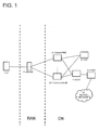
- Fig. 1 illustrates an exemplary embodiment 1 of the present invention.
- EPC Evolved Packet Core
- a UE 1 (user equipment) is a portable phone terminal (mobile terminal) or the like.
- the UE 1 may be the above described MTC device, MBMS-compatible terminal, or the like.
- An eNodeB 11 is a base station apparatus in LTE (Long Term Evolution).
- An MME 21 and an MME 22 are mobility management apparatuses introduced in EPC.
- the Customized MME 22 is a specific MME to which the UE 1 needs to be connected and the general MME (21) is an MME other than the Customized MME.
- the Customized MME 22 is configured as an MME customized for a machine communication (MTC) service and for terminals compatible therewith (M2M devices) (for example, reinforcement of C-Plane handling network control is carried out).
- MTC machine communication
- M2M devices for example, reinforcement of C-Plane handling network control is carried out.
- the Customized MME 22 may be configured as an MBMS-compatible MME.
- An HSS (Home Subscriber Server) 31 is a database storing subscriber information.
- An S-GW (Serving GateWay) 41 and a P-GW (Packet data network GateWay, which is also referred to as PDN-GW) 51 are apparatuses handling a user plane.
- a service network 61 is an external network.
- the eNodeB is an apparatus in a radio access network (RAN) and the MMEs, the S-GW, the P-GW, and so forth are apparatuses in a core network (CN).
- RAN radio access network
- CN core network
- Examples 1 to 5 correspond to the above Modes 1 to 5, respectively.
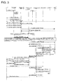
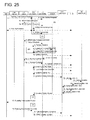
- Fig. 3 is a sequence diagram illustrating an example of an operation according to example 1.
- UE corresponds to the UE 1 in Fig. 1
- eNodeB corresponds to eNodeB 11 in Fig. 1
- general MME corresponds to the general MME 21 in Fig. 1
- Customerized MME corresponds to the Customized MME 22 in Fig. 1
- Serving GW corresponds to the S-GW 41 in Fig. 1
- PDN GW corresponds to the P-GW 51 in Fig. 1
- HSS corresponds to the HSS 31 in Fig. 1 .
- PCRF Policy and Charging Rules Function
- EIR Equipment Identity Register
- IMEI International Mobile Equipment Identity
- Fig. 3 for example, "1. Attach Request” represents that transmission of an Attach Request from the UE to the eNodeB is sequence 1. To distinguish the reference character of this sequence from reference character 1 of the UE in Fig. 1 (from the reference characters of the components), this sequence number 1 will be represented in parentheses as "Attach Request (1)" in the following description. The other sequence numbers are also represented in the same way. The sequence numbers in Fig. 4 and in the subsequent sequence diagrams will also be represented in the same way.
- Fig. 3 is based on Figure 5.3.2.1-1: Attach Procedure in 3GPP TS23.401 and the sequence numbers are in accordance with this figure. As for details of each sequence, reference may be made to description of 3GPP TS23.401 5.3.2. Hereinafter, the operation sequence will be described with reference to Figs. 1 and 3 .
- the eNodeB 11 when the UE 1 transmits an Attach Request (1), first, the eNodeB 11 receives the Attach Request (1). Next, the eNodeB 11 relays the Attach Request (2) to an MME.
- the eNodeB 11 cannot uniquely determine whether to forward the Attach Request (2) to the general MME 21 or to the Customized MME 22. Thus, there is a case where the eNodeB 11 forwards the Attach Request (2) to the general MME 21.
- the general MME 21 Upon reception of the Attach Request (2), the general MME 21 acquires terminal information (ME Identity) from the UE 1 using an Identity Request/Response (4, 5b).
- the general MME 21 transmits an ME Identity Check Request (5b) to the EIR, and the EIR transmits an MD Identity Check Ack to the general MME.
- the general MME 21 performs, in coordination with the HSS 31, authentication and acquires a subscriber profile. Namely, in this case, at least, the general MME 21 performs authentication and acquires a subscriber profile.
- the general MME 21 determines whether to connect the UE 1 to the general MME 21 or to the Customized MME 22.
- the general MME 21 determines that the UE 1 needs to be connected to the general MME 21, the general MME 21 continues a normal Attach Procedure.
- the general MME 21 determines that the UE 1 needs to be connected to the Customized MME 22, to instruct re-selection of an MME, the general MME 21 transmits an MME selection signal (an MME re-selection command) (S1AP (S1 application) signal newly introduced in the present exemplary embodiment) to the eNodeB 11.
- MME selection signal an MME re-selection command
- S1AP S1 application
- the general MME 21 sets an identifier of the Customized MME 22 (for example, a GUMMEI (Globally Unique MME Identity)) in the MME re-selection command signal. Namely, before a bearer is generated in the core network, the general MME 21 transmits to the eNodeB a re-selection request in which necessary information (GUMMEI) for selecting a new MME is included.
- GUMMEI Globally Unique MME Identity
- the MME have a function of deciding whether a UE is a re-selection target.
- the eNodeB 11 When the eNodeB 11 receives the MME re-selection command signal, in accordance with the identifier set in this signal, the eNodeB 11 selects the Customized MME 22 and forwards the Attach Request (2) to the Customized MME 22. Since the Customized MME 22 needs an NAS (Non-Access Stratum) parameter of the Attach Request (used for authentication between the UE and the MME), the eNodeB 11 transmits the Attach Request. The eNodeB 11 needs to have a function of storing the NAS message.
- NAS Non-Access Stratum
- the Customized MME 22 Upon reception of the Attach Request signal, the Customized MME 22 acquires the terminal information using an Identity Request/Response. Furthermore, the Customized MME 22 performs authentication and acquires a subscriber profile in coordination with the HSS 31. Namely, the Customized MME 22 performs the same processing as that performed by the general MME 21.
- the Customized MME 22 determines whether to connect the UE 1 to the general MME 21 or to the Customized MME 22.
- the Customized MME 22 since the Customized MME 22 has been re-selected by the eNodeB 11, the Customized MME 22 continues a normal Attach Procedure, without transmitting an MME re-selection command signal. Namely, the following operations are performed:
- the general MME 21 and the Customized MME 22 have a function of deciding which MME is to be connected to the UE 1. This decision is made based on information transmitted from the UE 1.
- the information may be:
- the Customized MME 22 can request the eNodeB 11 to select the general MME 21 in a like manner.
- MME instructs the eNodeB to perform MME re-selection.
- the eNodeB performs re-selection of an MME and the Attach Procedure is continued.
- the UE can be attached to an appropriate MME.
- example 2 another example with EPC (Evolved Packet Core) will be described.
- the UE transmits an Attach Request and the UE is connected to the Customized MME.
- the same system configuration as that in example 1 will be used.
- Fig. 4 is a sequence diagram illustrating an example of an operation according to example 2.
- Fig. 4 is based on Figure 5.3.2.1-1: Attach Procedure in 3GPP TS23.401 and the sequence numbers are in accordance with this figure. As for details of each sequence, reference may be made to description of TS23.401 5.3.2. Hereinafter, the operation will be described with reference to Figs. 1 and 4 .
- the eNodeB 11 When the UE 1 transmits an Attach Request (1), the eNodeB 11 receives the Attach Request (1). Next, the eNodeB 11 relays the Attach Request (2) to an MME. However, the eNodeB 11 cannot uniquely determine whether to forward the Attach Request (2) to the general MME 21 or to the Customized MME 22. Thus, there is a case where the eNodeB 11 forwards the Attach Request (2) to the general MME 21.
- the general MME 21 Upon reception of the Attach Request (2), the general MME 21 acquires terminal information (ME Identity) using an Identity Request/Response (5b). The general MME 21 performs, in coordination with the HSS 31, authentication and acquires a subscriber profile. Namely, in this case, at least, the general MME 21 performs authentication and acquires a subscriber profile.
- the general MME 21 determines whether to connect the UE 1 to the general MME 21 or to the Customized MME 22. When the general MME 21 determines that the UE 1 needs to be connected to the general MME 21, the general MME 21 continues a normal Attach Procedure.
- the general MME 21 determines that the UE 1 needs to be connected to the Customized MME 22, to instruct change of an MME, the general MME 21 transmits an MME change request signal (MME Change Request) (a GTP (GPRS Tunneling Protocol) signal newly introduced in the present example) to the Customized MME 22.
- MME Change Request a GTP (GPRS Tunneling Protocol) signal newly introduced in the present example
- the general MME 21 sets context information generated by authentication of the terminal and acquisition of the subscriber profile in the MME Change Request signal.
- the Customized MME 22 Upon reception of the MME change request signal (MME Change Request), the Customized MME 22 holds the context information set in the MME change request signal and transmits an MME Change Response signal (a GTP signal newly introduced in the present example) to the general MME 21.
- MME Change Request MME Change Request signal
- MME Change Response signal a GTP signal newly introduced in the present example
- the Customized MME 22 transmits an Update Location Request signal (8) to the HSS 31 to notify the HSS 31 that the MME has been changed.
- the Customized MME 22 transmits an Update Location Request.
- the subsequent Attach Procedure is performed by the Customized MME 22.
- the Customized MME 22 can omit performing re-authentication.
- Customized MME 22 continues the Attach Procedure and the eNodeB 11 receives an Initial Context Setup Request/Attach Accept (17) from the Customized MME 22.
- the Initial Context Setup Request/Attach Accept (17) is a response to the Attach Request (2) received by the general MME 21.
- the eNodeB 11 needs to include a function of receiving a Response from another MME different from the general MME 21.
- Customized MME 22 continues a normal Attach Procedure.
- the general MME 21 and the Customized MME 22 have a function of deciding which MME is to be connected to the UE 1, as is the case with example 1.
- the Customized MME 22 can request the general MME 21 for change of an MME in a like manner.
- the general MME instructs the Customized MME about change of an MME.
- the Customized MME performs the change of an MME and continues the Attach Procedure. In this way, the UE can be attached to an appropriate MME.
- example 3 another example with EPC will be described.
- the UE transmits an Attach Request and the UE is connected to the Customized MME.
- the same system configuration as that in example 1 will be used.
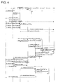
- Figs. 5 and 6 are sequence diagrams illustrating an example of an operation according to example 3.
- Figs. 5 and 6 are based on Figure 5.3.2.1-1: Attach Procedure in 3GPP TS23.401 and the sequence numbers are in accordance with these figures. As for details of each sequence, reference may be made to description of TS23.401 5.3.2. Hereinafter, the operation will be described with reference to Figs. 1 , 5 , and 6 .
- the eNodeB 11 When the UE 1 transmits an Attach Request (1), first, the eNodeB 11 receives the Attach Request (1). Next, the eNodeB 11 forwards the Attach Request (2) to an MME. However, the eNodeB 11 cannot uniquely determine whether to forward the Attach Request (2) to the general MME 21 or to the Customized MME 22. Thus, there is a case where the eNodeB 11 forwards the Attach Request (2) to the general MME 21.
- the general MME 21 Upon reception of the Attach Request (2), the general MME 21 acquires terminal information (ME Identity) using an Identity Request/Response (5b). The general MME 21 performs, in coordination with the HSS 31, authentication and acquires a subscriber profile.
- the general MME 21 determines whether to connect the UE 1 to the general MME 21 or to the Customized MME 22. When the general MME 21 determines that the UE 1 needs to be connected to the general MME 21, the general MME 21 continues a normal Attach Procedure.
- the general MME 21 determines that the UE 1 needs to be connected to the Customized MME 22, the general MME 21 transmits an Attach Reject message to the UE 1, instead of continuing the Attach Procedure. Namely, the general MME 21 transmits an Initial Context Setup Request/Attach Reject (17) to the eNodeB 11.
- the general MME 21 sets one or more parameters for instructing re-attach (a new parameter introduced in the present example) and a GUTI (Globally Unique Temporary Identify) parameter including a GUMMEI (Globally Unique MME identifier) (a new parameter introduced in the present example) in the Attach Reject signal, so that the eNodeB 11 can select the Customized MME 22 when performing re-attach.
- the GUTI parameter is formed by a GUMMEI and an M-TMSI (Temporary Mobile Station Identity).
- An MMEI is formed by an MCC (Mobile Country Code), an MNC (Mobile Network Code), and an MME Identifier. While these parameters are parameters that are newly introduced in the present example, since the eNodeB 11 is transparent to these parameters, the eNodeB 11 is not affected.
- the UE 1 Upon reception of the Attach Reject signal from the eNodeB 11, as illustrated in Fig. 6 , the UE 1 transmits the Attach Request (1) in which the GUTI has been set (Attach by the GUTI) to the eNodeB 11, in accordance with the parameter for instructing re-attach set in the Attach-Reject signal and the GUTI parameter.
- the eNodeB 11 determines that an appropriate MME from the GUMMEI included in the GUTI and forwards the Attach Request (2) to the Customized MME 22.
- the UE 1 has a function of receiving a GUTI in an Attach Reject signal and using the GUTI specified in the Attach Reject when transmitting a re-attach (Attach Request (1) in Fig. 6 ).
- a function of deciding whether this UE is a re-selection target is implemented.
- the Customized MME 22 continues a normal Attach Procedure. While the GUTI is set in the Attach Request, the Customized MME 22 does not hold context information.
- the Customized MME 22 upon reception of the Attach Request signal, acquires terminal information using an Identity Request/Response (4). Furthermore, the Customized MME 22 performs authentication and acquires a subscriber profile in coordination with the HSS 31.
- the general MME 21 and the Customized MME 22 have a function of deciding which MME is to be connected to the UE 1, as is the case with example 1.
- the Customized MME 22 can request the UE 1 for re-selection of an MME in a like manner.
- the general MME instructs the UE to perform re-selection of an MME.
- the UE specifies the Customized MME to continue an Attach Procedure. In this way, the UE can be attached to an appropriate MME.
- Fig. 7 is a sequence diagram illustrating an example of an operation according to example 4.
- Fig. 7 is based on Figure 5.3.2.1-1: Attach Procedure in 3GPP TS23.401 and the sequence numbers are in accordance with the figure. For details of each sequence, reference may be made to TS23.401 5.3.2.
- the operation will be described with reference to Figs. 1 and 7 .
- the UE 1 To transmit an Attach Request (1) to an MME, first, the UE 1 establishes RRC connection with the eNodeB 11. To establish RRC connection, first, the UE 1 transmits an RRC Connection Request signal to the eNodeB 11.
- the UE 1 sets one or more parameters indicating that the UE 1 needs to be connected to the Customized MME 22 (User Identity, a new Value or a new parameter of Establishment Cause (a value or a parameter newly introduced in the present example), or an identifier of a part of such a parameter (a PLMN-id (Public Land Mobile Network Identify) included in the IMSI, for example)).
- the Customized MME 22 User Identity, a new Value or a new parameter of Establishment Cause (a value or a parameter newly introduced in the present example), or an identifier of a part of such a parameter (a PLMN-id (Public Land Mobile Network Identify) included in the IMSI, for example)).
- PLMN-id Public Land Mobile Network Identify
- the UE 1 is implemented with a new parameter of the RRC Connection Request (a new Value or a new parameter of an establishment Cause (an information element (communication establishment cause) that indicates a cause of transmission of an RRC Connection Request)), wherein by using the RRC Connection Request, the UE 1 notifies the eNodeB that the UE 1 can be connected to the Customized MME.
- a new parameter of the RRC Connection Request a new Value or a new parameter of an establishment Cause (an information element (communication establishment cause) that indicates a cause of transmission of an RRC Connection Request)
- the eNodeB 11 Upon reception of the RRC Connection Request signal, the eNodeB 11 stores information indicating that the UE 1 needs to be connected to the Customized MME 22 and continues the subsequent RRC Connection Procedure.
- the UE 1 After establishing RRC Connection, the UE 1 transmits an Attach Request (1) and the eNodeB 11 receives the Attach Request (1). From the information (indicating that the UE 1 needs to be connected to the Customized MME 22) stored when the eNodeB 11 has received the RRC Connection Request (1), the eNodeB 11 forwards an Attach Request (2) to the Customized MME 22.
- the eNodeB 11 sets a new parameter of the RRC Connection Request (a new Value or a new parameter of Establishment Cause) in the Attach Request (2).
- the parameter indicates that the UE 1 can be connected to the Customized MME indicated in the RRC Connection Request. In this way, the eNodeB 11 notifies the Customized MME 22 of the new parameter.
- the Customized MME 22 Upon reception of the Attach Request (2), the Customized MME 22 continues a normal Attach Procedure.
- the Customized MME 22 holds the new parameter of the RRC Connection Request (a new Value or a new parameter of establishment Cause) received in the Attach Request (2).
- the parameter indicates that the UE 1 can be connected to the Customized MME indicated in the RRC Connection Request.
- the UE 1 has a function of instructing the eNodeB 11 about which one of the general MME 21 and the Customized MME 22 is to be connected to the UE 1. Since the UE 1 cannot store information about all the MMEs in the core network, information indicating an MME type, a service type, or the like is used for the instruction given to the eNodeB 11, instead of an identifier by which a unique MME can be selected.
- the eNodeB 11 has a function of deciding which MME is to be connected to the UE 1.
- one of or a combination of User Identity, a new Value or a new parameter of a communication establishment cause (Establishment Cause), and an identifier of a part of such a parameter in the RRC Connection Request is used for selection of an MME by the eNodeB 11.
- the new parameter include an APN and an ID that identifies an MTC group.
- the UE instructs the eNodeB to select an MME.
- the eNodeB specifies the Customized MME to continue an Attach Procedure. In this way, the UE can be attached to an appropriate MME.
- example 5 another example with EPC will be described.
- the UE and the Customized MME are connected when Tracking Area Update (TA Update) is performed.
- TA Update Tracking Area Update
- the same system configuration as that in example 1 will be used.
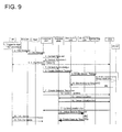
- Figs. 8 and 9 are sequence diagrams illustrating an example of an operation according to example 5.
- Fig. 8 is based on Figure 5.3.5-1: S1 Release Procedure in 3GPP TS23.401 (see TS23.401 5.3.5).
- Fig. 9 is based on Figure 5.3.3.1-1: Tracking Area Update procedure with Serving GW change. Reference may be made to 3GPP TS23.401 5.3.3). The operation will be described with reference to Figs. 1 , 8 , and 9 (and a part in Fig. 3 ).
- the eNodeB 11 When the UE 1 transmits an Attach Request (1 in Fig. 3 ), first, the eNodeB 11 receives the Attach Request. The eNodeB 11 relays the Attach Request to an MME (see 2 in Fig. 3 ).
- the eNodeB 11 cannot uniquely determine whether to forward the Attach Request to the general MME 21 or to the Customized MME 22. Thus, there is a case where the eNodeB 11 forwards the Attach Request to the general MME 21.
- the general MME 21 Upon reception of the Attach Request, the general MME 21 acquires terminal information using an Identity Request/Response (see 4 in Fig. 3 ). Furthermore, the general MME 21 performs authentication and acquires a subscriber profile in coordination with the HSS 31.
- the general MME 21 determines that the UE 1 needs to be connected to the Customized MME 22, the general MME 21 performs S1 Release to cause the UE 1 to perform Tracking Area Update (TA Update), as illustrated in Fig. 8 .
- the general MME 21 transmits an S1 UE context release command (4) to the eNodeB 11.
- the general MME 21 gives an instruction about an MME that the eNodeB needs to select when establishing S1 Connection with an MME next time, by using an MME identifier (for example, a GUMMEI) in the S1 UE context release command (4).
- MME identifier for example, a GUMMEI
- the UE 1 transmits a TAU Request (2), as illustrated in Fig. 9 .
- the eNodeB 11 receives the TAU Request (2) from the UE 1 and forwards the TAU Request (3) to an MME. Since S1 Release has already been performed, the eNodeB 11 performs re-selection of an MME and establishes S1 Connection.
- the Customized MME 22 Upon reception of the TAU Request (3), the Customized MME 22 continues a normal TA update procedure. The Customized MME 22 transmits a Context Request (4) to the general MME 21 and receives a Context Response (5) in response thereto.
- the Customized MME 22 transmits a Context Acknowledge (7) including an instruction for changing the S-GW to the general MME.
- the Customized MME 22 selects a new S-GW 41 (new Serving GW)
- the Customized MME 22 transmits a Create Session Request (8) to the new S-GW 41.
- the new S-GW 41 (new Serving GW) transmits a Modify Bearer Request (9) to the P-GW 51.
- the new S-GW Upon reception of a response to the Modify Bearer Request (9) from the P-GW 51, the new S-GW returns a Create Session Response (11) to the Customized MME 22.
- the general MME 21 Upon reception of a Cancel Location (13) from the HSS 31, the general MME 21 deletes MM context and transmits a Cancel Location Ack (14) to the HSS 31.
- the HSS 31 transmits an Updata Location Ack (17) in response to the Updata Location (12) to the Customized MME 22.
- the general MME 21 transmits a Delete Session Request (18) to the old S-GW 41 (old Serving GW), and the old S-GW 41 (old Serving GW) transmits a response (19) to the Delete Session Request (18) to the general MME 21.
- the Customized MME 22 transmits a TAU Accept (20) to the UE 1.
- the UE 1 If a GUTI is included in the TAU Accept (20), the UE 1 returns a TAU Complete (21) to the Customized MME 22. The UE 1 uses this TAU Complete (21) as an acknowledge response to the received signal TAU Accespt (20).
- the general MME 21 and the Customized MME 22 have a function of deciding which MME is to be connected to the UE 1. This function is the same as that in example 1.
- the TA update procedure has been performed based on the sequence in Fig. 9 .
- a feature in the present example is that the eNodeB 11 selects an MME.
- the present example can also be realized by, for example, other Procedures for re-establishing S1 Connection, such as a Service Request.
- the general MME instructs the eNodeB to perform re-selection of an MME.
- the eNodeB specifies the Customized MME in selecting the MME next time to continue the Procedure. In this way, the UE can be connected to an appropriate MME.
- a configuration with UMTS Universal Mobile Telecommunications System
- a UE transmits an Attach Request and the UE is connected to a Customized SGSN.
- Fig. 2 illustrates an example of a system configuration according to exemplary embodiment 2.
- a UE 101 is a portable phone terminal (mobile phone) or the like.
- the UE 101 may be the above MTC device or MBMS-compatible terminal.
- a NodeB 111 and an RNC (a radio network controller) 171 are apparatuses for Radio access adopted for the UMTS system.
- a general SGSN 121 and a Customized SGSN 122 are serving apparatuses used in the UMTS. Depending on the connection mode, the general SGSN 121 and the Customized SGSN 122 handle the user plane. If the SGSNs do not handle the user plane, the user plane is set between an S-GW and an RNC.
- An HLR (Home Location Register) 131 is a database storing subscriber information.
- a GGSN 141 (Gateway GPRS (general Packet Radio Service) Support Node: which is described as "gateway GPRS support node” in the claims) is a gateway apparatus connected to an external network.
- a service network 161 is an external network (data packet network).
- the NodeB 111 and the RNC 171 are apparatuses in a radio access network RAN and the SGSN, the GGSN, and so forth are apparatuses in a core network.
- MS Mobile Station
- RAN Radio Access Network
- general SGSN corresponds to the general SGSN 121 in Fig. 2
- Customized SGSN corresponds to the Customized SGSN 122 in Fig. 2
- GGSN corresponds to the GGSN 141 in Fig. 2
- HLR corresponds to the HLR 131 in Fig. 2 .
- a VLR of an MSC (Mobile Switching Center)/VLR (Visitor Location Register) is a location register for CS services other than the HLR.
- An EIR (Equipment Identifier Register) stores identifiers of valid mobile devices.
- the general SGSN 121 Upon reception of the Attach Request, the general SGSN 121 acquires terminal information using an Identity Request/Response (3). Furthermore, the general SGSN 121 performs authentication and acquires a subscriber profile, in coordination with the HLR 131. The general SGSN 121 performs authentication and acquires a subscriber profile.
- the general SGSN 121 when acquiring the terminal information and the subscriber profile, determines whether to connect the UE 101 to the general SGSN 121 or to the Customized SGSN 122. When the general SGSN 121 determines that the UE 101 needs to be connected to the general SGSN 121, the general SGSN 121 continues a normal Attach Procedure.
- the general SGSN 121 determines that the UE 101 needs to be connected to the Customized SGSN 122, in order to instruct re-selection of an SGSN, the general SGSN 121 transmits an SGSN re-selection command (an RANAP signal newly introduced in the present example) to the RNC 171.
- the general SGSN 121 sets an identifier identifying the Customized SGSN 122 in the SGSN re-selection command signal (for example, an RAI (routing area Identifier) or an NRI (Network Resource Identifier)).
- the general SGSN 121 embeds necessary information (RAI) for selecting the Customized SGSN 122 in an SGSN re-selection request and transmits the request to the RNC 171. If re-selection is performed within a single pool, only the NRI may be used.
- the SGSNs have a function of deciding whether the UE 101 is a re-selection target.
- the RNC 171 When the RNC 171 receives the SGSN re-selection command signal, in accordance with the identifier set in this signal, the RNC 171 selects the Customized SGSN 122 and forwards the Attach Request (1). Since the Customized SGSN 122 needs an NAS (Non Access Stratum) parameter of the Attach Request, the RNC 171 transmits the Attach Request. The RNC 171 has a function of storing such NAS message.
- the new SGSN cannot take over context.
- the new SGSN also needs to perform authentication and acquire the subscriber profile.
- the Customized SGSN 122 acquires terminal information using an Identity Request/Response.
- the Customized SGSN 122 performs authentication and acquires a subscriber profile, in coordination with the HLR 131. Namely, the Customized SGSN 122 performs the same processing as that performed by the general SGSN 121.
- the Customized SGSN 122 upon acquiring the terminal information and the subscriber profile, determines whether to connect the UE 101 to the general SGSN 121 or to the Customized SGSN 122. In this case, since the Customized SGSN 122 has been selected after re-selection by the RNC 171, the Customized SGSN 122 continues a normal Attach Procedure, without transmitting an SGSN re-selection command signal.
- the general SGSN 121 and the Customized SGSN 122 have a function of deciding which SGSN is to be connected to the UE 101. This decision is made based on information transmitted from the UE 101.
- the information may be:
- the above determination may be made based on information transmitted from the HLR 131.
- the information may be:
- an SGSN instructs the RNC to perform re-selection of an SGSN.
- the RNC performs re-selection of an SGSN and continues the Attach Procedure. In this way, the UE can be attached to an appropriate SGSN.
- the NodeB 111 When the UE 101 transmits an Attach Request (1), first, the NodeB 111 receives the Attach Request (1). Next, the NodeB 111 forwards the Attach Request to the RNC 171, and the RNC 171 forwards the Attach Request to an SGSN. However, the RNC 171 cannot uniquely determine whether to forward the Attach Request to the general SGSN 121 or to the Customized SGSN 122. Thus, there is a case where the RNC 171 forwards the Attach Request to the general SGSN 121.
- the general SGSN 121 Upon reception of the Attach Request, the general SGSN 121 acquires terminal information using an Identity Request/Response.
- the general SGSN 121 performs, in coordination with the HLR 131, authentication and acquires a subscriber profile. Namely, in this case, at least, the general SGSN 121 performs authentication and acquires a subscriber profile.
- the general SGSN 121 upon acquiring the terminal information and the subscriber profile, determines whether to connect the UE 101 to the general SGSN 121 or to the Customized SGSN 122. When the general SGSN 121 determines that the UE 101 needs to be connected to the general SGSN 121, the general SGSN 121 continues a normal Attach Procedure.
- the general SGSN 121 determines that the UE 101 needs to be connected to the Customized SGSN 122, to instruct change of an SGSN, the general SGSN 121 transmits an SGSN Change Request (a GTP signal newly introduced in the present exemplary embodiment) to the Customized SGSN 122.
- an SGSN Change Request (a GTP signal newly introduced in the present exemplary embodiment)
- the general SGSN 121 sets context information generated by authentication of the mobile terminal and acquisition of the subscriber profile in the SGSN Change Request signal. Namely, when the general SGSN 121 requests the Customized SGSN 122 for change of an SGSN (SGSN Change), the general SGSN 121 notifies a new SGSN (the Customized SGSN 122) of context.
- the SGSNs have a function of deciding whether the UE 101 is a re-selection target.
- the Customized SGSN 122 Upon reception of the SGSN Change Request signal, the Customized SGSN 122 holds the context information set in the SGSN Change Request signal and transmits an SGSN Change Response signal (a GTP signal newly introduced in the present exemplary embodiment) to the general SGSN 121.
- an SGSN Change Response signal (a GTP signal newly introduced in the present exemplary embodiment)
- the Customized SGSN 122 transmits an Update Location signal (8) to the HLR 131 to notify the HLR 131 of change of the SGSN.
- the Customized SGSN 122 can omit performing re-authentication.
- the Customized SGSN 122 continues the Attach Procedure and the RNC 171 receives an Attach Accept signal (9) from the Customized SGSN 122. Subsequently, a normal Attach Procedure is continued.
- the general SGSN 121 and the Customized SGSN 122 have a function of deciding which SGSN is to be connected to the UE 101, as is the case with example 6.
- the Customized SGSN 122 can request the general SGSN 121 for change of an SGSN in a like manner.
- the general SGSN instructs the Customized SGSN about change of an SGSN.
- the Customized SGSN performs the change of an SGSN and continues the Attach Procedure. In this way, the UE can be attached to an appropriate SGSN.
- Figs. 12 and 13 are sequence diagrams illustrating an operation according to example 8. Hereinafter, the operation will be described with reference to Figs. 2 , 12 , and 13 .
- the NodeB 111 When the UE 101 (MS) transmits an Attach Request (1), first, the NodeB 111 receives the Attach Request (1). Next, the NodeB 111 forwards the Attach Request to the RNC 171, and the RNC 171 forwards the Attach Request to an SGSN. However, the RNC 171 cannot uniquely determine whether to forward the Attach Request to the general SGSN 121 or to the Customized SGSN 122. Thus, there is a case where the RNC 171 forwards the Attach Request to the general SGSN 121.
- the general SGSN 121 Upon reception of the Attach Request (1), the general SGSN 121 acquires terminal information using an Identity Request/Response (3). The general SGSN 121 performs, in coordination with the HLR 131, authentication and acquires a subscriber profile.
- the general SGSN 121 Upon acquiring the terminal information and the subscriber profile, the general SGSN 121 determines whether to connect the UE 101 to the general SGSN 121 or to the Customized SGSN 122. When the general SGSN 121 determines that the UE 101 needs to be connected to the general SGSN 121, the general SGSN 121 continues a normal Attach Procedure.
- the general SGSN 121 determines that the UE 101 needs to be connected to the Customized SGSN 122, the general SGSN 121 transmits an Attach Reject signal (9) to the UE 101, instead of continuing the Attach Procedure.
- the general SGSN 121 sets one or more parameters for instructing re-attach and an RAI (routing area Identity) parameter (a parameter newly introduced in the present exemplary embodiment) in the Attach Reject signal, so that the RNC 171 can select the Customized SGSN 122 when performing re-attach. While these parameters are parameters that are newly introduced in the present example, since the RNC 171 is transparent, the RNC 171 is not affected.
- RAI routing area Identity
- the UE 101 needs to have a function of receiving an RAI via an Attach Reject and using the RAI specified in the Attach Reject when transmitting a Re-attach.
- the SGSNs have a function of deciding whether the UE 101 is a re-selection target.
- the UE 101 Upon reception of the Attach Reject signal (9), as illustrated in Fig. 13 , the UE 101 transmits the Attach Request signal (1), in which the RAI is set, to the RNC 171, in accordance with the parameter for instructing re-attach set in the Attach Reject signal (9) and the RAI parameter (re-attach by a P-TMSI (Packet Temporary Mobile Subscriber Indentifier)).
- the RNC 171 determines an appropriate SGSN from the RAI and forwards the Attach Request to the Customized SGSN 122.
- Customized SGSN 122 continues a normal Attach Procedure.
- the Customized SGSN 122 While the RAI is set in the attach request, the Customized SGSN 122 does not hold context information. Thus, upon reception of the Attach Request signal (1), the Customized SGSN 122 acquires terminal information using an Identity Request/Response (3). Furthermore, the Customized SGSN 122 performs authentication and acquires a subscriber profile in coordination with the HLR 131.
- the general SGSN 121 and the Customized SGSN 122 have a function of deciding which SGSN is to be connected to the UE 101, as is the case with example 6.
- the Customized SGSN 122 can request the UE 101 for re-selection of an SGSN in a like manner.
- the general SGSN instructs the UE to perform re-selection of an SGSN.
- the UE specifies the Customized SGSN to continue an Attach Procedure. In this way, the UE can be attached to an appropriate SGSN.
- Fig. 14 is a sequence diagram illustrating an example of an operation according to example 9. Hereinafter, the operation will be described with reference to Figs. 2 and 14 .
- the UE 101 To transmit an Attach Request to an SGSN, first, the UE 101 establishes RRC Connection with the RNC 171. To establish RRC Connection, first, the UE 101 transmits an RRC Connection Request signal to the RNC 171.
- the UE 101 sets one or more parameters indicating that the UE 101 needs to be connected to the Customized SGSN 122 (User Identity, a new Value or a new parameter of Establishment Cause (a value or a parameter newly introduced in the present example), or an identifier of a part of such a parameter (a PLMN-id included in the IMSI, for example)).
- the Customized SGSN 122 User Identity, a new Value or a new parameter of Establishment Cause (a value or a parameter newly introduced in the present example), or an identifier of a part of such a parameter (a PLMN-id included in the IMSI, for example)).
- the RNC 171 Upon reception of the RRC Connection Request signal, the RNC 171 stores information indicating that the UE 101 needs to be connected to the Customized SGSN 122 and continues the subsequent RRC Connection Procedure.
- the UE 101 After establishing RRC Connection, the UE 101 transmits an Attach Request (1) and the NodeB 111 receives the Attach Request (1). Next, the NodeB 111 forwards the Attach Request to the RNC 171.
- the RNC 171 forwards the Attach Request to an SGSN. From the information stored when the RNC 171 has received the RRC Connection Request signal, the RNC 171 forwards the Attach Request signal to the Customized SGSN 122.
- the RNC 171 sets one or more parameters indicating that the UE 101 needs to be connected to the Customized SGSN 122 (User Identity, a new Value or a new parameter of Establishment Cause (a value or a parameter newly introduced in the present example), or an identifier of a part of such a parameter (a PLMN-id included in the IMSI, for example)) received via the RRC Connection Request signal in the Attach Request and notifies the Customized SGSN 122 of the information.
- the Customized SGSN 122 Upon reception of the Attach Request, the Customized SGSN 122 continues a normal Attach Procedure.
- the Customized SGSN 122 holds the parameter indicating that the UE 101 needs to be connected to the Customized SGSN 122 received via the Attach Request (the parameter received by the RNC 171 via the RRC Connection Request such as User Identity, a new Value or a new parameter of Establishment Cause (a value or a parameter newly introduced in the present example), or an identifier of a part of such a parameter (a PLMN-id included in the IMSI, for example).
- the UE 101 has a function of instructing the RNC 171 about which one of the general SGSN 121 and the Customized SGSN 122 is to be connected to the UE 101.
- the UE 101 cannot store information about all the SGSNs in the core network, and information indicating an SGSN type, a service type, or the like is used for the instruction given to the RNC 171, instead of an identifier by which a unique SGSN can be selected.
- the RNC 171 has a function of deciding which SGSN is to be connected to the UE 101. For this decision, as described above, one of or a combination of User Identity, a new Value or a new parameter of Establishment Cause (a value or a parameter newly introduced in the present example), and an identifier of a part of such a parameter is used.
- the new parameter include an ID that identifies an MTC group and an APN.
- the UE 101 instructs the RNC 171 to select an SGSN.
- the RNC 171 specifies the Customized SGSN to continue an Attach Procedure is continued. In this way, the UE 101 can be attached to an appropriate SGSN.
- Figs. 15 and 16 are sequence diagrams illustrating an example of an operation according to example 10. Hereinafter, the operation will be described with reference to Figs. 2 , 15 , 16 , and a part of Fig. 10 .
- the NodeB 111 When the UE 101 transmits an Attach Request (see 1 in Fig. 10 ), first, the NodeB 111 receives the Attach Request. The NodeB 111 forwards the Attach Request to the RNC 171, and the RNC 171 forwards the Attach Request to an SGSN. However, the RNC 171 cannot uniquely determine whether to forward the Attach Request to the general SGSN 121 or to the Customized SGSN 122. Thus, there is a case where the RNC 171 forwards the Attach Request to the general SGSN 121.
- the general SGSN 121 Upon reception of the Attach Request, the general SGSN 121 acquires terminal information using an Identity Request/Response (see 3 in Fig. 10 ). The general SGSN 121 performs authentication and acquires a subscriber profile in coordination with the HLR 131.
- the general SGSN 121 Upon acquiring the terminal information and the subscriber profile, the general SGSN 121 determines whether to connect the UE 101 to the general SGSN 121 or to the Customized SGSN 122. When the general SGSN 121 determines that the UE 101 needs to be connected to the general SGSN 121, the general SGSN 121 continues a normal Attach Procedure.
- the general SGSN 121 determines that the UE 101 needs to be connected to the Customized SGSN 122, the general SGSN 121 performs Iu release to cause the UE 101 to perform RA (routing area) update, as illustrated in Fig. 15 .
- RA routing area
- the general SGSN 121 transmits an IU release command signal to the RNC 171 (see 4 in Fig. 15 ).
- the general SGSN 121 gives an instruction about an SGSN that the RNC needs to select when establishing Iu Connection with an SGSN next time, by using an SGSN identifier (for example, an RAI or an NRI) in the IU release command signal.
- an SGSN identifier for example, an RAI or an NRI
- the NRI may be used.
- the RNC 171 Even after Iu release is completed, while the RNC 171 is holding session information for the UE 101, the RNC 171 continues to hold the SGSN identifier as information for next time selection of the SGSN.
- the UE 101 After Iu release is performed (after the RNC 171 transmits IU release complete (6) to the general SGSN 121), next, as illustrated in Fig. 16 , the UE 101 transmits an RAU request (RA update request) (2).
- RAU request RA update request
- the NodeB 111 receives the RAU Request (2), and the NodeB 111 forwards the RAU Request (3) to the RNC 171.
- the RNC 171 forwards the RAU request (3) to an SGSN. Since Iu release has already been performed, the RNC 171 performs selection of an SGSN and establishes Iu connection.
- the RNC 171 selects the Customized SGSN 122 in accordance with the SGSN Identifier specified in the Iu release command signal received from the general SGSN 121.
- the RNC has a function of holding the next RAI per UE.
- the Customized SGSN 122 Upon reception of the RAU request, the Customized SGSN 122 continues a normal RA Update Procedure. Since the P-TMSI (RAI) on the NAS indicates the general SGSN, which is the old SGSN, the Customized SGSN 122 acquires context.
- RAI P-TMSI
- the general SGSN 121 and the Customized SGSN 122 have a function of deciding which SGSN is to be connected to the UE 101. This function is the same as that in example 6.
- the Customized SGSN 122 can request the UE 101 to perform re-selection of an MME in a like manner.
- the RA Update Procedure is used in the sequences in Fig. 16 .
- this Procedure is used for selecting an SGSN by the RNC 171
- another Procedure for re-establishing Iu Connection such as PDP Context Activation, may be used.
- the general SGSN instructs the RNC to perform re-selection of an SGSN.
- the RNC specifies the Customized SGSN in selecting an SGSN next time and continues the Procedure. In this way, the UE can be connected to an appropriate SGSN.
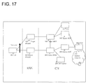
- Fig. 17 illustrates an example of a configuration (system configuration) according to example 11.
- the configuration includes a UE 201 and a handover-Source eNodeB (Source eNodeB) 202 and a handover destination Target eNodeB (target eNodeB) 203 in the RAN (radio access network) to which the UE 201 is wirelessly connected.
- Source eNodeB Handover-Source eNodeB
- target eNodeB Target eNodeB
- the CN core network
- the CN includes a Source MME 204, a Target MME 205, a Source SGW 206, a Target SGW 207, a DNS server 209, an HSS 211, and a PGW 208 connected to a service network 210.
- both the handover Source MME 204 and the Target MME 205 are Customized MMEs.
- Fig. 18 is a sequence diagram illustrating an example of an operation (a sequence operation) according to example 11.
- Fig. 18 is based on Figure 5.5.1.2.2-1: S1-based handover in 3GPP TS23.401, and the sequence numbers are in accordance with this figure. As for details of each sequence, reference may be made to description of TS23.401 5.5.1.2.2.
- the operation will be described with reference to Figs. 17 and 18 .
- the handover-Source eNodeB 202 When the handover-Source eNodeB 202 detects deterioration of a signal used for connection to the UE 201, the handover-Source eNodeB 202 transmits a Handover Required (2) to the Source MME 204. Information such as a Target TAI (Tracking Area Identity) is included in the Handover Required (2).
- the Source MME 204 refers to the information and determines execution of an inter-MME handover to the Target MME 205.
- the Source MME 204 uses information of a customized MME connection request held therein.
- the information of a customized MME connection request held in the Source MME 204 will be described.
- the eNodeB 202 receives from the UE 201 an RRC signal to which information of a customized MME connection request for connecting to a Customized MME is added.
- the eNodeB 202 notifies the Source MME 204, which is the Customized MME, of the information of a customized MME connection request via an S1-AP signal or the like.
- the information of a customized MME connection request is held in the Source MME 204.
- the Source MME 204 may use a local configuration held in the Source MME 204, based on the information of a customized MME connection request held in the Source MME 204.
- the local configuration is set by an operator and is information (configuration information) internally managed and held by the apparatus (MME) (for example, the configuration information includes information based on an MTC group and a handover destination mobility area, the information used when an MTC subscriber (MTC terminal) performs a handover).
- the Source MME 204 refers to the APN and uses local information (local configuration) that corresponds to the value of LAPI (Low Access Priority Indication) to select an MME that is a handover destination.
- the Source MME 204 may use a local configuration held therein to select the Target MME 205.
- the Source MME 204 may select the Target MME 205 by setting the information of the Customized MME connection request along with location information such as a target TAI (Tracking Area Identity) and issuing "DNS Query" to the DNS server 209.
- target TAI Tracking Area Identity
- the Source MME 204 determines execution of an Inter-MME handover to the Target MME 205, the Source MME 204 transmits a Forward Relocation Request (3) to the Target MME 205. In this operation, the Source MME 204 may set the information of a customized MME connection request held therein in the Forward Relocation Request (3).
- Target MME 205 executes another Inter-MME handover, the Target MME 205 can select a Customized MME by using the information of a customized MME connection request held therein.
- Inter-MME handover processing may be performed in accordance with related technology.
- SRNS Serving Radio Network Subsystem
- Handover Between Customized SGSNs in UMTS will be described.
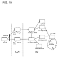
- Figs. 19 and 20 illustrate example 12.
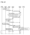
- Fig. 21 is a sequence diagram illustrating an example of an operation according to example 12.
- the configuration includes a UE 301 and a handover-Source RNC 302 and a handover destination Target RNC 303 in the RAN (radio access network) to which the UE 301 is wirelessly connected.
- the CN Core Network
- the CN includes a Source SGSN 304, a Target SGSN 305, a Source SGW 306, a Target SGW 307, a DNS server 309, an HSS 311, and a PGW 308.
- the UE 301 is connected to a service network 310 via the PGW 308.
- both the handover-Source SGSN 304 and the Target SGSN 305 are Customized SGSNs.
- FIG. 21 is based on Figure 39: SRNS Relocation Procedure in 3GPP TS23.060, and the sequence numbers are in accordance with this figure. As for details of each sequence, reference may be made to the description of 3GPP TS23.060 6.9.2.2.1 (while a terminal is denoted by MS (Mobile Station) in Figure 39 of 3GPP TS23.060, the terminal is denoted by UE in Fig. 21 ).
- Fig. 19 illustrates an example in which the CN is configured by EPC. Since no particular difference is seen as to the operation according to example 12, the operation according to the present example is effective with the configuration illustrated in Figs. 19 and 20 .
- the CN in Fig. 20 is different from the CN in Fig. 19 in that the Source SGW 306 and the Target SGW 307 are not included and that a GGSN 408 is included in place of the PGW 308 in Fig. 19 .
- the Source RNC 402 when the Source RNC 402 detects deterioration of a signal used for connection to the UE 401, the Source RNC 402 transmits a relocation required (2) to the Source SGSN 404.
- Information such as a target ID is included in the relocation required (2).
- the Source SGSN 404 refers to the information and determines execution of an inter-SGSN SRNS (Serving Radio Network Subsystem) relocation to the Target SGSN 405.
- SRNS Serving Radio Network Subsystem
- the Source SGSN 404 uses the information of a customized-SGSN connection request held therein.
- the information of a customized SGSN connection request held in the Source SGSN 404 will be described.
- the RNC 403 receives from the UE 401 an RRC (Radio Resource Control) signal to which information of a customized-SGSN connection request for connecting to a Customized SGSN is added.
- the RNC 403 notifies the Source SGSN 404, which is the Customized SGSN, of the information of a customized SGSN connection request via an Iu signal.
- the information of a customized MME connection request is held in the Source SGSN 404.
- the Source SGSN 404 may use a local configuration, based on the information of a customized SGSN connection request held in the Source SGSN 404. Alternatively, the Source SGSN 404 may use a local configuration held therein to select the Target SGSN 405. The Source SGSN 404 may select the Target SGSN 405 by setting the information of a customized SGSN connection request along with location information such as a target ID and issuing "DNS Query" to the DNS server 409.
- the Source SGSN 404 determines execution of an inter-SGSN SRNS relocation to the Target SGSN 405, the Source SGSN 404 transmits a Forward Relocation Request (3) to the Target SGSN 405.
- the Source SGSN 404 may set the information of a customized SGSN connection request held therein in this signal (forward relocation request).
- Target SGSN 405 executes another inter-SGSN SRNS relocation
- the Target SGSN 405 can select a Customized SGSN by using the information of a customized-SGSN connection request.
- inter-SGSN SRNS relocation processing is performed in accordance with related technology.
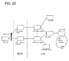
- Fig. 22 illustrates an example of a configuration according to example 13.
- the configuration includes a UE 501 and a Source eNodeB 502 and a Target eNodeB 503 in the RAN (radio access network) to which the UE 501 is wirelessly connected.
- the CN core network
- the CN includes a Source MME 504, a Target SGSN 505, an SGW 506, a DNS server 508, an HSS 510, and a PGW 507 connected to a service network 509.
- Fig. 23 is a sequence diagram illustrating an example of an operation according to example 13.
- Fig. 23 is a sequence diagram illustrating an example of an operation according to example 13.
- the Source eNodeB 502 When the Source eNodeB 502 detects deterioration of a signal used for connection to the UE 501, the Source eNodeB 502 transmits a Handover Required (2) to the Source MME 504. Information such as Target TAI (Tracking Area ID) is included in the Handover Required (2).
- the Source MME 504 refers to the information and determines execution of an inter-RAT (Radio Access Technology) handover to the Target SGSN 505.
- the Source MME 504 uses information of a customized MME connection request held therein.
- the Source MME 504 may use a local configuration, based on the information of a customized MME connection request.
- the Source MME 504 may use a local configuration held therein to select the Target SGSN 505.
- the Source MME 504 may select the Target SGSN 505 by setting the information of a customized MME connection request along with location information such as a target ID and issuing "DNS Query" to the DNS server 508.
- the Source MME 504 determines execution of an Inter RAT handover to the Target SGSN 505, the Source MME 504 transmits a Forward Relocation Request (3) to the Target SGSN 505.
- the Source MME 504 may set the information of a customized MME connection request held therein in this signal.
- the Target SGSN 505 executes another Inter RAT handover, the Target SGSN 505 can select a Customized MME by using the information of a customized MME connection request.
- Inter RAT handover processing is performed in accordance with related technology.
- example 14 an example of a handover from a Customized SGSN to a customize MME in EPC will be described. While the configuration according to example 14 is the same as that illustrated in Fig. 22 , the handover is performed in the opposite direction.
- the sequence illustrating an example of an operation according to example 14 is basically the same as that illustrated in Fig. 23 , except that the description (operation sequence) of the SGSN and the description (operation sequence) of the MME are switched and that the description (operation sequence) of the RNC and the description (operation sequence) of the eNodeB are reversed (the sequence operation is performed in the opposite direction).
- a UE transmits a Tracking Area Update (TAU) and the UE is connected to a Customized MME.
- TAU Tracking Area Update
- the configuration according to example 15 is the same as that according to example 1.
- Fig. 24 is a sequence diagram illustrating an example of an operation according to example 15.
- Fig. 24 is based on Figure 5.3.3.1-1: Tracking Area Update procedure with Serving GW change in 3GPP TS23.401, and the sequence numbers are in accordance with the figure. As for details of each sequence, reference may be made to description of TS23.401 5.3.3. The following describes the operation with reference to Figs. 1 and 24 .
- the UE 1 To transmit a TAU Request (3) to an MME, first, the UE 1 establishes RRC (Radio Resource Control) connection with the eNodeB 11. To establish RRC Connection, first, the UE 1 transmits an RRC Connection Request signal to the eNodeB 11.
- RRC Radio Resource Control
- the UE 1 sets one or more parameters indicating that the UE 1 needs to be connected to the Customized MME 22 (User Identity, a new Value or a new parameter of Establishment Cause (a value or a parameter newly introduced in the present example), or an identifier of a part of such a parameter (a PLMN-id included in the IMSI, for example)).
- the Customized MME 22 User Identity, a new Value or a new parameter of Establishment Cause (a value or a parameter newly introduced in the present example), or an identifier of a part of such a parameter (a PLMN-id included in the IMSI, for example)).
- the UE 1 is implemented with a new parameter of the RRC Connection Request (a new Value or a new parameter of Establishment Cause).
- a new parameter of the RRC Connection Request a new Value or a new parameter of Establishment Cause.
- the eNodeB 11 Upon reception of the RRC Connection Request signal, the eNodeB 11 stores information indicating that the UE 1 needs to be connected to the Customized MME 22 and continues the subsequent RRC connection procedure.
- the UE 1 After establishing RRC connection, the UE 1 transmits a TAU Request (2) and the eNodeB 11 receives the TAU Request (2). From the information stored when the eNodeB 11 has received the RRC Connection Request, the eNodeB 11 forwards a TAU Request (3) to the Customized MME 22. The eNodeB 11 sets a new parameter of the RRC Connection Request (a new Value or a new parameter of Establishment Cause) to notify that the UE 1 can be connected to the Customized MME received in the RRC Connection Request, in the TAU Request (3). The eNodeB 11 notifies the Customized MME 22 of the new parameter.
- a new parameter of the RRC Connection Request a new Value or a new parameter of Establishment Cause
- the Customized MME 22 Upon reception of the TAU Request (3), the Customized MME 22 continues a normal TAU Procedure.
- the Customized MME 22 holds the new parameter of the RRC Connection Request (a new Value or a new parameter of Establishment Cause) to notify that the UE 1 can be connected to the Customized MME received in the RRC Connection Request, the new parameter being set in the received TAU Request (3).
- the UE 1 may have a function of instructing the eNodeB 11 about which one of the general MME 21 and the Customized MME 22 is to be connected to the UE 1. Since the UE 1 cannot store information about all the MMEs in the core network, information indicating an MME type, a service type, or the like is used for the instruction given to the eNodeB 11, instead of an identifier by which a unique MME can be selected.
- the eNodeB 11 may have a function of deciding which MME is to be connected to the UE 1.
- one of or a combination of User Identity, a new Value or a new parameter of a communication establishment cause (Establishment Cause), and an identifier of a part of such a parameter in the RRC Connection Request is used for selection of an MME by the eNodeB 11.
- the new parameter include an APN and an ID that identifies an MTC group.
- the UE instructs the eNodeB to select an MME.
- the eNodeB specifies the Customized MME to continue a TAU Procedure. In this way, an appropriate MME can be caused to register the location of the UE.
- a UE transmits a Routing Area Update signal and the UE is connected to a Customized SGSN.
- the configuration according to example 16 is the same as that according to example 6.
- Fig. 25 is a sequence diagram illustrating an example of an operation according to example 16.
- Fig. 25 is based on Figure 36: Iu mode RA Update procedure in 3GPP TS23.060, and the sequence numbers are in accordance with the figure.
- TS23.060 6.9.2 while a terminal is denoted by MS in Figure 36 of 3GPP TS23.060, the terminal is denoted by UE in Fig. 25 ).
- the UE 101 In order to transmit a Routing Area Update Request to an SGSN, first, the UE 101 establishes RRC connection with the RNC 11. In order to establish RRC Connection, first, the UE 101 transmits an RRC Connection Request signal to the RNC 171.
- the UE 101 sets one or more parameters indicating that the UE 101 needs to be connected to the Customized SGSN 122 (User Identity, a new Value or a new parameter of Establishment Cause (a value or a parameter newly introduced in the present example), or an identifier of a part of such a parameter (a PLMN-id included in the IMSI, for example)).
- the Customized SGSN 122 User Identity, a new Value or a new parameter of Establishment Cause (a value or a parameter newly introduced in the present example), or an identifier of a part of such a parameter (a PLMN-id included in the IMSI, for example)).
- the RNC 171 Upon reception of the RRC Connection Request signal, the RNC 171 stores information indicating that the UE 101 needs to be connected to the Customized SGSN 122 and continues the subsequent RRC connection procedure.
- the UE 101 After establishing RRC connection, the UE 101 transmits a Routing Area Update Request (1), and the NodeB 111 receives the Routing Area Update Request (1). Next, the NodeB 111 forwards the Routing Area Update Request (1) to the RNC 171.
- the RNC 171 forwards the Routing Area Update Request (1) to an SGSN. From the information stored in the RNC 171 upon reception of the RRC Connection Request signal, the RNC 171 forwards the Routing Area Update Request (1) to the Customized SGSN 122. In the Routing Area Update Request, the RNC 171 sets one or more parameters (User Identity, a new Value or a new parameter of Establishment Cause (a new Value or parameter introduced in the present example), or an identifier of a part of such a parameter (a PLMN-id included in the IMSI, for example)). As indicated in the RRC Connection Request received by the RNC 171, the parameter indicates that the UE 101 needs to be connected to the Customized SGSN 122. Thus, the Customized SGSN 122 is notified of the parameter.
- the RNC 171 indicates that the UE 101 needs to be connected to the Customized SGSN 122.
- the Customized SGSN 122 Upon reception of the Routing Area Update Request, the Customized SGSN 122 continues a normal Routing Area Update procedure.
- the Customized SGSN 122 holds the parameter (User Identity, a new Value or a new parameter of Establishment Cause (a new Value or parameter introduced in the present example), or an identifier of a part of such a parameter (a PLMN-id included in the IMSI, for example)), the parameter set in the received Routing Area Update Request and indicating that the UE 101 needs to be connected to the Customized SGSN 122.
- the parameter User Identity, a new Value or a new parameter of Establishment Cause (a new Value or parameter introduced in the present example), or an identifier of a part of such a parameter (a PLMN-id included in the IMSI, for example)
- the UE 101 has a function of instructing the RNC 171 about which one of the general SGSN 121 and the Customized SGSN 122 is to be connected to the UE 1. Since the UE 101 cannot store information about all the SGSNs in the core network, information indicating an SGSN type, a service type, or the like is used for the instruction given to the RNC 171, instead of an identifier by which a unique SGSN can be selected.
- the RNC 171 has a function of deciding which SGSN is to be connected to the UE 101. As described above, this decision is performed by using User Identity, a new Value or a new parameter of Establishment Cause (a new Value or parameter introduced in the present example), an identifier of a part of such a parameter (a PLMN-id included in the IMSI, for example), or a combination thereof. Examples of the new parameter include an APN and an ID that identifies an MTC group.
- the UE 101 instructs the RNC 171 to select an SGSN.
- the RNC 171 specifies the Customized SGSN to continue a Routing Area Update Procedure. In this way, the UE 101 can perform location registration in an appropriate SGSN.
- CN core network
- An MTC (Machine Type Communication) device (an M2M device) is connected to a customized CN node (a node streamlined for MTC devices).
- a user using the MBMS is connected to a customized CN node (an MBMS-compatible CN node).
- the service is provided only by a customized CN node(s).
- a specific UE is connected to a node in which an MME and an SGW are collocated.
- an MME and an SGW are collocated.
- SMS Short Message Service
- MMEs may be sorted depending on a terminal type (CSFB (CS Fallback) terminal and a VoLTE terminal, for example).
- CSFB CS Fallback
- VoLTE Voice over LTE
- the CSFB terminal needs to interwork with an MSC.
- the VoLTE terminal needs to interwork with an IMS.
- CSFB an MSC that is first attached is caused to select a collocated MME.
Landscapes
- Engineering & Computer Science (AREA)
- Computer Networks & Wireless Communication (AREA)
- Signal Processing (AREA)
- Mobile Radio Communication Systems (AREA)
- Telephonic Communication Services (AREA)
- Medical Preparation Storing Or Oral Administration Devices (AREA)
Applications Claiming Priority (3)
| Application Number | Priority Date | Filing Date | Title |
|---|---|---|---|
| JP2013141127 | 2013-07-04 | ||
| JP2013187106 | 2013-09-10 | ||
| EP14820719.4A EP2996393A4 (de) | 2013-07-04 | 2014-07-04 | Kommunikationssystem, -verfahren und -vorrichtung |
Related Parent Applications (2)
| Application Number | Title | Priority Date | Filing Date |
|---|---|---|---|
| EP14820719.4A Division EP2996393A4 (de) | 2013-07-04 | 2014-07-04 | Kommunikationssystem, -verfahren und -vorrichtung |
| EP14820719.4A Division-Into EP2996393A4 (de) | 2013-07-04 | 2014-07-04 | Kommunikationssystem, -verfahren und -vorrichtung |
Publications (2)
| Publication Number | Publication Date |
|---|---|
| EP3029992A2 true EP3029992A2 (de) | 2016-06-08 |
| EP3029992A3 EP3029992A3 (de) | 2016-07-20 |
Family
ID=52143859
Family Applications (2)
| Application Number | Title | Priority Date | Filing Date |
|---|---|---|---|
| EP14820719.4A Withdrawn EP2996393A4 (de) | 2013-07-04 | 2014-07-04 | Kommunikationssystem, -verfahren und -vorrichtung |
| EP16153026.6A Withdrawn EP3029992A3 (de) | 2013-07-04 | 2014-07-04 | Kommunikationssystem, -verfahren und -vorrichtung |
Family Applications Before (1)
| Application Number | Title | Priority Date | Filing Date |
|---|---|---|---|
| EP14820719.4A Withdrawn EP2996393A4 (de) | 2013-07-04 | 2014-07-04 | Kommunikationssystem, -verfahren und -vorrichtung |
Country Status (13)
| Country | Link |
|---|---|
| US (3) | US9883440B2 (de) |
| EP (2) | EP2996393A4 (de) |
| JP (4) | JP5862840B2 (de) |
| KR (4) | KR20180053436A (de) |
| CN (2) | CN105611585B (de) |
| BR (2) | BR112015032906A2 (de) |
| CL (2) | CL2015003718A1 (de) |
| MX (2) | MX345250B (de) |
| MY (2) | MY162436A (de) |
| PH (4) | PH12016500012B1 (de) |
| RU (4) | RU2602088C1 (de) |
| UA (2) | UA116025C2 (de) |
| WO (1) | WO2015002290A1 (de) |
Cited By (1)
| Publication number | Priority date | Publication date | Assignee | Title |
|---|---|---|---|---|
| US11004683B2 (en) | 2018-01-15 | 2021-05-11 | Toshiba Memory Corporation | Imprint apparatus, imprint method, and method of manufacturing semiconductor device |
Families Citing this family (34)
| Publication number | Priority date | Publication date | Assignee | Title |
|---|---|---|---|---|
| EP3198926A4 (de) * | 2014-09-26 | 2017-10-25 | Telefonaktiebolaget LM Ericsson (publ) | Verwaltung von überlastung in mindestens einem kernnetzwerk |
| US9807669B1 (en) * | 2014-10-24 | 2017-10-31 | Sprint Communications Company L.P. | Identifying communication paths based on packet data network gateway status reports |
| JP2016122887A (ja) * | 2014-12-24 | 2016-07-07 | 富士通株式会社 | 無線基地局、無線デバイス、無線通信システム、及び、無線通信制御方法 |
| EP3245838B1 (de) * | 2015-01-13 | 2021-03-10 | Nec Corporation | Kommunikationsgerät, kernnetzwerkknoten, system und verfahren zur umleitung von nas-nachrichten |
| JP6668591B2 (ja) * | 2015-02-04 | 2020-03-18 | 日本電気株式会社 | 通信装置、通信システム、通信方法及びプログラム |
| JPWO2016125493A1 (ja) * | 2015-02-04 | 2017-11-16 | 日本電気株式会社 | 通信システム |
| CN106332222A (zh) | 2015-07-02 | 2017-01-11 | 北京三星通信技术研究有限公司 | 一种网络选择的方法和基站 |
| JP6177845B2 (ja) * | 2015-08-13 | 2017-08-09 | 株式会社Nttドコモ | 基地局、管理装置及び接続方法 |
| JP6603400B2 (ja) * | 2015-08-14 | 2019-11-06 | テレフオンアクチーボラゲット エルエム エリクソン(パブル) | パケットデータネットワーク接続を管理するためのノード及び方法 |
| GB2541247A (en) * | 2015-08-14 | 2017-02-15 | Nec Corp | Communication system |
| WO2017079074A1 (en) | 2015-11-06 | 2017-05-11 | Interdigital Patent Holdings, Inc. | Methods, core network entity and wireless transmit/receive unit (wtru) using enhanced dedicated core network (dcn) selection |
| EP4030796B1 (de) * | 2015-11-19 | 2026-04-15 | SK Telecom Co., Ltd. | Verfahren und vorrichtung zur auswahl eines kernnetzwerks in einem mobilkommunikationssystem |
| US9749773B2 (en) | 2015-12-04 | 2017-08-29 | At&T Intellectual Property I, L.P. | Core network selection function in a radio access network for machine-to-machine (M2M) communications |
| KR102468945B1 (ko) * | 2016-03-08 | 2022-11-21 | 삼성전자 주식회사 | 핸드오버를 지원하는 방법 및 장치 |
| US10243860B2 (en) * | 2016-04-05 | 2019-03-26 | Nokia Technologies Oy | Method and apparatus for end-to-end QoS/QoE management in 5G systems |
| US10567495B2 (en) | 2016-11-16 | 2020-02-18 | Cisco Technology, Inc. | Application based intelligent edge computing in a low power wide area network environment |
| WO2018111029A1 (ko) * | 2016-12-15 | 2018-06-21 | 엘지전자(주) | 무선 통신 시스템에서 핸드오버 수행 방법 및 이를 위한 장치 |
| WO2018142263A1 (en) * | 2017-02-03 | 2018-08-09 | Nokia Technologies Oy | Method and system for selection of an access and mobility management function in an access network environment |
| US10299184B1 (en) * | 2017-03-28 | 2019-05-21 | Sprint Communications Company L.P. | Reselection of optimal network elements |
| KR102475109B1 (ko) * | 2017-04-28 | 2022-12-07 | 광동 오포 모바일 텔레커뮤니케이션즈 코포레이션 리미티드 | 혼잡 처리를 위한 방법 및 기기 |
| JP7286741B2 (ja) * | 2017-04-28 | 2023-06-05 | オッポ広東移動通信有限公司 | 輻輳処理のための方法及び機器 |
| US10021557B1 (en) | 2017-08-18 | 2018-07-10 | Verizon Patent And Licensing Inc. | Universal GUTI for simplified device onboarding |
| US9998896B1 (en) * | 2017-08-18 | 2018-06-12 | Verizon Patent And Licensing Inc. | Dedicated APN access using default network access key for profile download |
| US10952052B2 (en) * | 2017-10-11 | 2021-03-16 | Blackberry Limited | Method and system for dynamic APN selection |
| US11310038B2 (en) * | 2018-03-02 | 2022-04-19 | Nitto Denko Corporation | System and method for securing data communication between computers |
| US12520127B2 (en) | 2018-04-05 | 2026-01-06 | Ntt Docomo, Inc. | User equipment, network device, and radio communication method |
| US11076321B2 (en) * | 2018-10-11 | 2021-07-27 | Cisco Technology, Inc. | Selecting 5G non-standalone architecture capable MME during registration and handover |
| US11290951B2 (en) | 2019-02-12 | 2022-03-29 | Cisco Technology, Inc. | Providing optimal packet data network gateway selection for 5G network environments upon initial user equipment attachment via a WiFi evolved packet data gateway |
| CN111954269B (zh) * | 2019-05-15 | 2022-11-01 | 华为技术有限公司 | 一种承载修改方法及接入网设备 |
| JP6896793B2 (ja) * | 2019-05-27 | 2021-06-30 | 本田技研工業株式会社 | 情報処理装置 |
| WO2021014328A1 (en) * | 2019-07-19 | 2021-01-28 | Reliance Jio Infocomm Limited | System and method for supporting standalone 5g radio with legacy network |
| KR20210125380A (ko) * | 2020-04-08 | 2021-10-18 | 삼성전자주식회사 | 무선 통신 시스템에서 음성 핸드오버 지원 방법 및 장치 |
| JP7478823B2 (ja) * | 2020-05-26 | 2024-05-07 | 株式会社Nttドコモ | 端末装置及び端末装置の制御方法 |
| US20220286853A1 (en) * | 2021-03-03 | 2022-09-08 | At&T Intellectual Property I, L.P. | Mobility management for aggressive devices |
Citations (1)
| Publication number | Priority date | Publication date | Assignee | Title |
|---|---|---|---|---|
| JP2003338832A (ja) | 2002-05-22 | 2003-11-28 | Nec Corp | パケット転送経路の最適化方法及びパケット転送装置並びにプログラム |
Family Cites Families (35)
| Publication number | Priority date | Publication date | Assignee | Title |
|---|---|---|---|---|
| WO2001091382A1 (en) | 2000-05-22 | 2001-11-29 | Nokia Corporation | System and method for providing a connection in a communication network |
| NO20014064D0 (no) * | 2001-08-21 | 2001-08-21 | Ericsson Telefon Ab L M | Fremgangsmate for handtering av en mobil abonnent i et telekommunikasjonssystem |
| EP1820301A4 (de) | 2004-12-09 | 2012-10-17 | Samsung Electronics Co Ltd | Verfahren und System zum Verschieben der bedienenden Funknetzsteuerung in einem Netzwerkverteilungssystem |
| WO2007102953A1 (en) * | 2006-03-08 | 2007-09-13 | Interdigital Technology Corporation | Method and apparatus for supporting handoff and serving radio network subsystem relocation procedures in a single tunnel gprs-based wireless communication system |
| US20070254667A1 (en) * | 2006-04-28 | 2007-11-01 | Joanna Jokinen | Inter-MME handover in evolved communication systems |
| JP4848890B2 (ja) | 2006-08-23 | 2011-12-28 | 日本電気株式会社 | 移動通信システム及びその方法並びにそれに用いる基地局 |
| US20090023448A1 (en) | 2007-02-21 | 2009-01-22 | Qualcomm Incorporated | Method and apparatus for inter-system handover |
| CN101309500B (zh) | 2007-05-15 | 2011-07-20 | 华为技术有限公司 | 不同无线接入技术间切换时安全协商的方法和装置 |
| KR101547544B1 (ko) * | 2008-09-24 | 2015-08-27 | 삼성전자주식회사 | 펨토 기지국으로의 핸드 오버를 위한 통신 시스템 및 이를 위한 방법 |
| WO2010057198A1 (en) * | 2008-11-17 | 2010-05-20 | Starent Networks, Corp | Dynamic load balancing in a communication network |
| CN101420724B (zh) * | 2008-11-20 | 2011-02-02 | 华为技术有限公司 | 信息传输方法、移动管理设备和网络系统 |
| JPWO2011001628A1 (ja) | 2009-07-03 | 2012-12-10 | パナソニック株式会社 | コネクション管理方法、コネクション管理システム、移動端末、パケットデータゲートウェイ並びに移動管理ゲートウェイ |
| KR20110020161A (ko) | 2009-08-21 | 2011-03-02 | 엘지전자 주식회사 | 이동통신 네트워크 내에서 제어 평면(Control Plane)을 담당하는 서버 및 SIPTO 기반의 세션을 제어하는 방법 |
| CN102056138B (zh) | 2009-11-05 | 2016-08-03 | 中兴通讯股份有限公司 | 本地ip访问连接的管理方法及装置 |
| US9307390B2 (en) | 2010-01-08 | 2016-04-05 | Gemalto Sa | Group based mobility optimization method and device in machine-type communication |
| KR101609580B1 (ko) * | 2010-02-10 | 2016-04-07 | 삼성전자주식회사 | 무선 통신 시스템 및 그의 사용자 단말기와 이동성 관리 엔티티 간 연결 방법 |
| CN102469543B (zh) * | 2010-11-05 | 2015-09-16 | 中兴通讯股份有限公司 | 接纳控制方法、装置及系统 |
| WO2012062193A1 (zh) * | 2010-11-08 | 2012-05-18 | 中兴通讯股份有限公司 | Mtc切换中的拥塞控制方法及装置、系统 |
| WO2012137402A1 (ja) * | 2011-04-04 | 2012-10-11 | パナソニック株式会社 | セル選択方法、セル選択システム、通信デバイス及び基地局 |
| WO2012147291A1 (ja) | 2011-04-28 | 2012-11-01 | パナソニック株式会社 | 通信ノード及びネットワークノード |
| US8625534B2 (en) * | 2011-05-20 | 2014-01-07 | At&T Intellectual Property I, L.P. | Throughput for inter-radio access technology handover |
| WO2012172729A1 (ja) | 2011-06-14 | 2012-12-20 | 日本電気株式会社 | 移動通信システム、その制御方法および制御プログラムを格納した非一時的なコンピュータ可読媒体 |
| AU2012294284A1 (en) * | 2011-08-11 | 2014-02-27 | Interdigital Patent Holdings, Inc. | Mobile relay handover |
| EP2745607A1 (de) * | 2011-08-19 | 2014-06-25 | Interdigital Patent Holdings, Inc. | Verfahren und vorrichtung zur verwendung von non-access-stratum-prozeduren in einer mobilstation zum zugriff auf ressourcen von zu unterschiedlichen funkzugangstechnologien gehörenden komponententrägern |
| CN102984775B (zh) * | 2011-09-06 | 2015-12-16 | 普天信息技术研究院有限公司 | 无线接入网络信息管理信息的获取方法 |
| EP2763496B1 (de) * | 2011-09-30 | 2018-08-01 | Nec Corporation | Kommunikationssystem, -verfahren und -vorrichtung |
| JP5922902B2 (ja) | 2011-09-30 | 2016-05-24 | 日本信号株式会社 | 無線通信ネットワークシステムの同期方法 |
| EP2608567A1 (de) * | 2011-12-13 | 2013-06-26 | Panasonic Corporation | Vorrichtungsauslösungs- und -verstopfungssteuerung |
| EP2806605A4 (de) | 2012-01-20 | 2015-09-02 | Samsung Electronics Co Ltd | Verfahren und vorrichtung zur einstellung der priorität von datenübertragung |
| JP5229403B1 (ja) * | 2012-01-26 | 2013-07-03 | 日本電気株式会社 | 移動局、移動局の制御方法、移動通信システム、移動管理装置、及びプログラム |
| KR101565102B1 (ko) | 2012-04-04 | 2015-11-02 | 주식회사 케이티 | 이중 우선순위 어플리케이션을 갖는 기계 형태 통신 장치에 대한 접속 제어 방법 및 장치 |
| EP2693800A1 (de) * | 2012-08-03 | 2014-02-05 | Panasonic Corporation | Funkressourcenmanagement für dualen Prioritätszugang |
| US9055520B2 (en) | 2012-12-19 | 2015-06-09 | Cisco Technology, Inc. | Systems, methods and media for mobile management entity (MME) selection by Evolved Node B (eNodeB) |
| US9973966B2 (en) | 2013-01-11 | 2018-05-15 | Interdigital Patent Holdings, Inc. | User-plane congestion management |
| WO2014135210A1 (en) * | 2013-03-07 | 2014-09-12 | Nokia Solutions And Networks Oy | Handover of mobility management entity for load balancing |
-
2014
- 2014-04-07 UA UAA201600857A patent/UA116025C2/uk unknown
- 2014-07-04 JP JP2015525288A patent/JP5862840B2/ja active Active
- 2014-07-04 KR KR1020187013659A patent/KR20180053436A/ko not_active Ceased
- 2014-07-04 RU RU2016103470/07A patent/RU2602088C1/ru active
- 2014-07-04 KR KR1020167026957A patent/KR20160117641A/ko not_active Ceased
- 2014-07-04 KR KR1020167009283A patent/KR101663451B1/ko active Active
- 2014-07-04 BR BR112015032906A patent/BR112015032906A2/pt not_active Application Discontinuation
- 2014-07-04 UA UAA201604773A patent/UA117761C2/uk unknown
- 2014-07-04 MX MX2016000202A patent/MX345250B/es active IP Right Grant
- 2014-07-04 CN CN201610109364.2A patent/CN105611585B/zh active Active
- 2014-07-04 EP EP14820719.4A patent/EP2996393A4/de not_active Withdrawn
- 2014-07-04 WO PCT/JP2014/067891 patent/WO2015002290A1/ja not_active Ceased
- 2014-07-04 RU RU2016138812A patent/RU2642477C1/ru active
- 2014-07-04 KR KR1020167003159A patent/KR101651807B1/ko active Active
- 2014-07-04 MY MYPI2016000253A patent/MY162436A/en unknown
- 2014-07-04 MX MX2016001671A patent/MX349184B/es unknown
- 2014-07-04 US US14/902,656 patent/US9883440B2/en active Active
- 2014-07-04 BR BR122016004704-0A patent/BR122016004704A2/pt not_active Application Discontinuation
- 2014-07-04 MY MYPI2015704781A patent/MY157550A/en unknown
- 2014-07-04 EP EP16153026.6A patent/EP3029992A3/de not_active Withdrawn
- 2014-07-04 RU RU2016112137/07A patent/RU2600131C1/ru active
- 2014-07-04 CN CN201480038357.7A patent/CN105359581A/zh active Pending
-
2015
- 2015-10-30 JP JP2015213913A patent/JP5862830B1/ja not_active Expired - Fee Related
- 2015-12-10 JP JP2015241405A patent/JP2016034164A/ja active Pending
- 2015-12-23 CL CL2015003718A patent/CL2015003718A1/es unknown
-
2016
- 2016-01-04 PH PH12016500012A patent/PH12016500012B1/en unknown
- 2016-03-04 US US15/061,120 patent/US20160192263A1/en not_active Abandoned
- 2016-03-08 PH PH12016500439A patent/PH12016500439B1/en unknown
- 2016-03-11 CL CL2016000582A patent/CL2016000582A1/es unknown
- 2016-12-12 JP JP2016240483A patent/JP2017050895A/ja active Pending
-
2017
- 2017-01-06 PH PH12017500046A patent/PH12017500046A1/en unknown
- 2017-12-13 US US15/840,649 patent/US20180146406A1/en not_active Abandoned
- 2017-12-25 RU RU2017145593A patent/RU2669792C1/ru active
-
2018
- 2018-10-25 PH PH12018502264A patent/PH12018502264A1/en unknown
Patent Citations (1)
| Publication number | Priority date | Publication date | Assignee | Title |
|---|---|---|---|---|
| JP2003338832A (ja) | 2002-05-22 | 2003-11-28 | Nec Corp | パケット転送経路の最適化方法及びパケット転送装置並びにプログラム |
Non-Patent Citations (1)
| Title |
|---|
| "3rd Generation Partnership Project; Technical Specification Group Services and System Aspects; Intra-domain connection of Radio Access Network (RAN) nodes to multiple Core Network (CN) nodes (Release 12)", 24 June 2013 (2013-06-24), XP050707895, Retrieved from the Internet <URL:http://www.3gpp.org/ftp/tsg_sa/WG2_Arch/Latest_SA2_Specs/DRAFT_INTERIM/> [retrieved on 20130624] * |
Cited By (2)
| Publication number | Priority date | Publication date | Assignee | Title |
|---|---|---|---|---|
| US11004683B2 (en) | 2018-01-15 | 2021-05-11 | Toshiba Memory Corporation | Imprint apparatus, imprint method, and method of manufacturing semiconductor device |
| US11837469B2 (en) | 2018-01-15 | 2023-12-05 | Kioxia Corporation | Imprint apparatus, imprint method, and method of manufacturing semiconductor device |
Also Published As
Similar Documents
| Publication | Publication Date | Title |
|---|---|---|
| US9883440B2 (en) | System, method, and apparatus for establishing a connection between a terminal and a network node | |
| US9686774B2 (en) | Communication system, method, and apparatus |
Legal Events
| Date | Code | Title | Description |
|---|---|---|---|
| PUAI | Public reference made under article 153(3) epc to a published international application that has entered the european phase |
Free format text: ORIGINAL CODE: 0009012 |
|
| 17P | Request for examination filed |
Effective date: 20160127 |
|
| AC | Divisional application: reference to earlier application |
Ref document number: 2996393 Country of ref document: EP Kind code of ref document: P |
|
| AK | Designated contracting states |
Kind code of ref document: A2 Designated state(s): AL AT BE BG CH CY CZ DE DK EE ES FI FR GB GR HR HU IE IS IT LI LT LU LV MC MK MT NL NO PL PT RO RS SE SI SK SM TR |
|
| AX | Request for extension of the european patent |
Extension state: BA ME |
|
| PUAL | Search report despatched |
Free format text: ORIGINAL CODE: 0009013 |
|
| AK | Designated contracting states |
Kind code of ref document: A3 Designated state(s): AL AT BE BG CH CY CZ DE DK EE ES FI FR GB GR HR HU IE IS IT LI LT LU LV MC MK MT NL NO PL PT RO RS SE SI SK SM TR |
|
| AX | Request for extension of the european patent |
Extension state: BA ME |
|
| RIC1 | Information provided on ipc code assigned before grant |
Ipc: H04W 36/00 20090101AFI20160613BHEP |
|
| RBV | Designated contracting states (corrected) |
Designated state(s): AL AT BE BG CH CY CZ DE DK EE ES FI FR GB GR HR HU IE IS IT LI LT LU LV MC MK MT NL NO PL PT RO RS SE SI SK SM TR |
|
| STAA | Information on the status of an ep patent application or granted ep patent |
Free format text: STATUS: REQUEST FOR EXAMINATION WAS MADE |
|
| R17P | Request for examination filed (corrected) |
Effective date: 20160127 |
|
| STAA | Information on the status of an ep patent application or granted ep patent |
Free format text: STATUS: EXAMINATION IS IN PROGRESS |
|
| 17Q | First examination report despatched |
Effective date: 20210324 |
|
| STAA | Information on the status of an ep patent application or granted ep patent |
Free format text: STATUS: THE APPLICATION IS DEEMED TO BE WITHDRAWN |
|
| 18D | Application deemed to be withdrawn |
Effective date: 20221013 |