EP3030423B1 - Appareil séparateur à cyclone et procédés de production - Google Patents
Appareil séparateur à cyclone et procédés de production Download PDFInfo
- Publication number
- EP3030423B1 EP3030423B1 EP14834531.7A EP14834531A EP3030423B1 EP 3030423 B1 EP3030423 B1 EP 3030423B1 EP 14834531 A EP14834531 A EP 14834531A EP 3030423 B1 EP3030423 B1 EP 3030423B1
- Authority
- EP
- European Patent Office
- Prior art keywords
- wear resistant
- casing
- liner
- elements
- cyclone
- Prior art date
- Legal status (The legal status is an assumption and is not a legal conclusion. Google has not performed a legal analysis and makes no representation as to the accuracy of the status listed.)
- Active
Links
Images


Classifications
-
- B—PERFORMING OPERATIONS; TRANSPORTING
- B04—CENTRIFUGAL APPARATUS OR MACHINES FOR CARRYING-OUT PHYSICAL OR CHEMICAL PROCESSES
- B04C—APPARATUS USING FREE VORTEX FLOW, e.g. CYCLONES
- B04C5/00—Apparatus in which the axial direction of the vortex is reversed
- B04C5/08—Vortex chamber constructions
- B04C5/085—Vortex chamber constructions with wear-resisting arrangements
-
- B—PERFORMING OPERATIONS; TRANSPORTING
- B32—LAYERED PRODUCTS
- B32B—LAYERED PRODUCTS, i.e. PRODUCTS BUILT-UP OF STRATA OF FLAT OR NON-FLAT, e.g. CELLULAR OR HONEYCOMB, FORM
- B32B37/00—Methods or apparatus for laminating, e.g. by curing or by ultrasonic bonding
- B32B37/12—Methods or apparatus for laminating, e.g. by curing or by ultrasonic bonding characterised by using adhesives
-
- B—PERFORMING OPERATIONS; TRANSPORTING
- B01—PHYSICAL OR CHEMICAL PROCESSES OR APPARATUS IN GENERAL
- B01D—SEPARATION
- B01D45/00—Separating dispersed particles from gases or vapours by gravity, inertia, or centrifugal forces
- B01D45/12—Separating dispersed particles from gases or vapours by gravity, inertia, or centrifugal forces by centrifugal forces
- B01D45/16—Separating dispersed particles from gases or vapours by gravity, inertia, or centrifugal forces by centrifugal forces generated by the winding course of the gas stream, the centrifugal forces being generated solely or partly by mechanical means, e.g. fixed swirl vanes
-
- B—PERFORMING OPERATIONS; TRANSPORTING
- B02—CRUSHING, PULVERISING, OR DISINTEGRATING; PREPARATORY TREATMENT OF GRAIN FOR MILLING
- B02C—CRUSHING, PULVERISING, OR DISINTEGRATING IN GENERAL; MILLING GRAIN
- B02C17/00—Disintegrating by tumbling mills, i.e. mills having a container charged with the material to be disintegrated with or without special disintegrating members such as pebbles or balls
- B02C17/18—Details
- B02C17/22—Lining for containers
-
- B—PERFORMING OPERATIONS; TRANSPORTING
- B29—WORKING OF PLASTICS; WORKING OF SUBSTANCES IN A PLASTIC STATE IN GENERAL
- B29C—SHAPING OR JOINING OF PLASTICS; SHAPING OF MATERIAL IN A PLASTIC STATE, NOT OTHERWISE PROVIDED FOR; AFTER-TREATMENT OF THE SHAPED PRODUCTS, e.g. REPAIRING
- B29C65/00—Joining or sealing of preformed parts, e.g. welding of plastics materials; Apparatus therefor
- B29C65/70—Joining or sealing of preformed parts, e.g. welding of plastics materials; Apparatus therefor by moulding
-
- G—PHYSICS
- G01—MEASURING; TESTING
- G01N—INVESTIGATING OR ANALYSING MATERIALS BY DETERMINING THEIR CHEMICAL OR PHYSICAL PROPERTIES
- G01N3/00—Investigating strength properties of solid materials by application of mechanical stress
- G01N3/56—Investigating resistance to wear or abrasion
-
- A—HUMAN NECESSITIES
- A47—FURNITURE; DOMESTIC ARTICLES OR APPLIANCES; COFFEE MILLS; SPICE MILLS; SUCTION CLEANERS IN GENERAL
- A47L—DOMESTIC WASHING OR CLEANING; SUCTION CLEANERS IN GENERAL
- A47L9/00—Details or accessories of suction cleaners, e.g. mechanical means for controlling the suction or for effecting pulsating action; Storing devices specially adapted to suction cleaners or parts thereof; Carrying-vehicles specially adapted for suction cleaners
- A47L9/10—Filters; Dust separators; Dust removal; Automatic exchange of filters
- A47L9/16—Arrangement or disposition of cyclones or other devices with centrifugal action
- A47L9/1608—Cyclonic chamber constructions
-
- B—PERFORMING OPERATIONS; TRANSPORTING
- B04—CENTRIFUGAL APPARATUS OR MACHINES FOR CARRYING-OUT PHYSICAL OR CHEMICAL PROCESSES
- B04C—APPARATUS USING FREE VORTEX FLOW, e.g. CYCLONES
- B04C5/00—Apparatus in which the axial direction of the vortex is reversed
- B04C5/02—Construction of inlets by which the vortex flow is generated, e.g. tangential admission, the fluid flow being forced to follow a downward path by spirally wound bulkheads, or with slightly downwardly-directed tangential admission
- B04C5/04—Tangential inlets
-
- B—PERFORMING OPERATIONS; TRANSPORTING
- B04—CENTRIFUGAL APPARATUS OR MACHINES FOR CARRYING-OUT PHYSICAL OR CHEMICAL PROCESSES
- B04C—APPARATUS USING FREE VORTEX FLOW, e.g. CYCLONES
- B04C5/00—Apparatus in which the axial direction of the vortex is reversed
- B04C5/12—Construction of the overflow ducting, e.g. diffusing or spiral exits
- B04C5/13—Construction of the overflow ducting, e.g. diffusing or spiral exits formed as a vortex finder and extending into the vortex chamber; Discharge from vortex finder otherwise than at the top of the cyclone; Devices for controlling the overflow
-
- B—PERFORMING OPERATIONS; TRANSPORTING
- B29—WORKING OF PLASTICS; WORKING OF SUBSTANCES IN A PLASTIC STATE IN GENERAL
- B29K—INDEXING SCHEME ASSOCIATED WITH SUBCLASSES B29B, B29C OR B29D, RELATING TO MOULDING MATERIALS OR TO MATERIALS FOR MOULDS, REINFORCEMENTS, FILLERS OR PREFORMED PARTS, e.g. INSERTS
- B29K2063/00—Use of EP, i.e. epoxy resins or derivatives thereof, as moulding material
-
- B—PERFORMING OPERATIONS; TRANSPORTING
- B29—WORKING OF PLASTICS; WORKING OF SUBSTANCES IN A PLASTIC STATE IN GENERAL
- B29K—INDEXING SCHEME ASSOCIATED WITH SUBCLASSES B29B, B29C OR B29D, RELATING TO MOULDING MATERIALS OR TO MATERIALS FOR MOULDS, REINFORCEMENTS, FILLERS OR PREFORMED PARTS, e.g. INSERTS
- B29K2105/00—Condition, form or state of moulded material or of the material to be shaped
- B29K2105/06—Condition, form or state of moulded material or of the material to be shaped containing reinforcements, fillers or inserts
- B29K2105/16—Fillers
-
- B—PERFORMING OPERATIONS; TRANSPORTING
- B29—WORKING OF PLASTICS; WORKING OF SUBSTANCES IN A PLASTIC STATE IN GENERAL
- B29K—INDEXING SCHEME ASSOCIATED WITH SUBCLASSES B29B, B29C OR B29D, RELATING TO MOULDING MATERIALS OR TO MATERIALS FOR MOULDS, REINFORCEMENTS, FILLERS OR PREFORMED PARTS, e.g. INSERTS
- B29K2509/00—Use of inorganic materials not provided for in groups B29K2503/00 - B29K2507/00, as filler
- B29K2509/02—Ceramics
Definitions
- This disclosure relates to a cyclone separator apparatus and methods for its production. It has particular application to a cyclone separator lining apparatus and a method of producing a wear resistant cyclone separator for minerals processing, and for illustrative purposes will be described with reference to this application. However we envisage that the apparatus disclosed may find use in other applications, such as producing a wear resistant cyclone separator for refractory materials generally.
- Cyclonic separation is a method of removing particulates from an air, gas or liquid stream, without the use of filters, through vortex separation. Rotational effects and gravity are used to separate mixtures of solids and fluids.
- a high speed rotating flow of heterogeneous material is established within a vertical, inverted, frusto-conical housing.
- the material flows in a helical pattern, beginning at the top (wide end) of the cyclone and ending at the bottom (narrow) end before exiting the cyclone in a straight stream through the centre of the cyclone and out the top.
- Larger and denser particles in the rotating stream have too much inertia to follow the tight curve of the stream, and strike the outside wall, then falling to the bottom of the cyclone where they are removed in an underflow.
- CN202909835 describes an abrasion-resistant swirler which is composed of an overflow conduit, an overflow pipe, an involute feeding port, a cavity and a desilting port.
- the cavity is formed by the combination of three layers of structures among which is a steel casing arranged at an outer layer, a one-piece ceramic liner arranged in the inner layer, and a protective layer made of high polymer materials arranged between the steel casing and the one-piece ceramic liner.
- US6686752 describes a vessel including a continuous electrical conductor embedded in the wall of the vessel for sensing when the lining has eroded.
- the refractory layer of the vessel is applied by a trowel in a paste form onto a metallic support structure.
- Ceramic lined cyclones are wear resistant separators used commonly in the art of minerals processing.
- a steel, truncated-conical cyclone body has outward-directed, radial flanged ends configured to accept inlet and outlet assemblies, and an inner conical wall surface.
- Tapered blocks of sintered alumina or a like ceramic are progressively glued on the inner conical wall surface to build up a wear-resistant surface.
- embodiments are disclosed of a method of forming a wear resistant minerals processing body, said method characterised by the steps of:
- the wear resistant minerals processing body may be a cyclone separator body or lower cone and spigot assembly.
- the processing body may be another static or rotating part, including but not limited to rotating drums and tumblers, lined pipe portions subject to accelerated wear and the like.
- the wear resistant elements may comprise any suitable material of hardness, and other physical and/or chemical properties fit for the chosen purpose. Such materials may be limited in size due to the processes for their formation, requiring use in assemblies of wear resistant elements. Alternatively, the parts may be chosen to allow refurbishment by partial replacement.
- the wear resistant materials may comprise isostatically hot pressed sintered materials including but not limited to alumina, silica, clay minerals, carbides or the like.
- the wear resistant material may be a fired or cast material.
- the wear resistant materials may be used as-formed or may be machined or ground in post-forming.
- the wear resistant elements may be selected from specific shapes selected to fit in close abutment to form the substantially continuous surface.
- the wear resistant elements may comprise specifically shaped elements adapted to form in assembly a frusto-conical wear surface with minimal gaps between the elements.
- the surface formed by the wear elements is continuous in being both substantially smooth and substantially void free.
- the wear resistant elements may be of different radial thickness.
- the lining may wear more aggressively in the lower (narrower) regions of the cyclone. It may therefore be beneficial to be able to use thicker linings in this region of the cyclone. As the wear surface is laid up on a form, and the space is selectable, the method may readily accommodate different lining thickness. This offers cost and weight savings by avoiding having a thick lining throughout.
- the wear resistant elements may be retained in position on the form by any suitable means.
- individual rows of wear elements may be retained by tie wire, adhesive tape or the like.
- the adhesive tape may be adapted to accommodate a tapering form for a hydrocyclone liner by any suitable means such as lateral elastic or plastic deformation.
- the tape may comprise unidirectional fibre-reinforced tape, cross hatch reinforced tape or the like.
- the form plays no part in the end use and as a consequence may be of any material adapted to support the wear resistant elements in position for the purposes of the method.
- the form may have a substantially truncated-conical outer surface against which the wear resistant elements may be assembled.
- the form may be made of sheet metal,
- the casing may be formed of sheet or plate metal, be cast of metal, polyurethanes or laminated in reinforced polymer, as the duty requires.
- the casing is usually of steel.
- the casing may be provided with end flanges; a cyclone separator body assembly may be provided with flanges at both ends in order to be mounted to inlet and lower cone and spigot equipment respectively.
- the space may be of any cross sectional dimension subject to permitting infiltration of the settable material.
- the settable material may in certain applications be a resilient material such as polyurethane or rubber material.
- the material may in use penetrate the fine cracks between elements to prevent ingress of the mineral materials being processed.
- the materials resilience offers improved impact absorption properties to the ceramic tile lining.
- the settable material may comprise a mineral filled resin bound material.
- the mineral may comprise ceramic beads.
- the binder may comprise epoxy resin.
- Such materials maybe selected to deform minimally under the expected loads while offering a high degree of abrasion resistance. This resistance to abrasive wear in conjunction with the wear indicating mechanism outlined hereunder will allow the settable material to act as a secondary wear barrier once the primary tile lining has worn through thus facilitating planned maintenance or replacement.
- the cross sectional dimension of the space is at least 5 mm, and preferably from 5 to about 25 mm.
- the lining material wears, irrespective of its wear resistance.
- composite minerals processing elements having a generally metallic outer housing lined with a wear resistant usually ceramic material are difficult to remote sense for wear by penetrating radiation or ultrasound. This may be due at least in part to the dispersive effect of the respective material boundaries.
- This limitation means that ceramic wear linings can only be measured by mechanical or visual means. This requires extended downtime given the need to disassemble the cyclone prior to inspection and measurement.
- the monitoring or testing may be done by remote sensing or other means of measurement from the outside of the closed equipment.
- the monitoring means may include one or more transducers, connected either singly or in arrays to an interface external of the body member. The transducer(s) may directly measure the thickness of a wear resistant element or elements in its location.
- the monitoring means may comprise one or more conductors each forming a continuity tester having an interface external of the body member, whereby wear through the wear resistant elements renders the conductor electrically discontinuous as monitored at the interface.
- the wear resistant liner may be provided by assembling wear resistant elements to form the liner, as described above, in this context and hereinafter, the "outer surface" of the wear resistant liner is the surface opposed to the inner surface.
- the inner surface is the surface exposed to a high wear environment. Wear through to the outer surface indicates a test failure state of the primary liner per se.
- the settable adhesive material may comprise a secondary wear resistant layer to provide time-to-shutdown flexibility on determination of a worn condition of the wear resistant liner at the interface.
- a secondary wear material is a mineral filled resin bound settable composition, such as a ceramic bead filled epoxy resin bound composition.
- the monitoring elements may include one or more transducers, connected either singly or in arrays to an interface external of the body member.
- the transducer may directly measure the thickness of a wear resistant element or elements it its location.
- the monitoring elements may comprise one or more conductors each forming a continuity tester, whereby wear through the wear resistant elements renders the conductor electrically discontinuous as monitored at the interface.
- the conductor or conductors may be insulated by an abrasively frangible insulative material, or the conductor insulated from itself at junctions, to permit laying up in a grid pattern on the wear resistant liner. Insulation may be particularly desirable to prevent leakage of current through conductivity of a mineral filler of the resin bound settable composition.
- the conductor or conductors may be spirally wound about the outer surface where there are no crossovers.
- the conductor or conductors may be arranged in a zigzag, sinuous or other "up and back" pattern selected to provide practical wear-indicating coverage for the primary wear liner.
- the conductor or conductors may comprise an insulated wire conductor.
- the insulated wire conductor may comprise a multifilament cable for flexibility.
- a generally axial zigzag or sinuous pattern may have a spacing of the apices of the conductor at the frusto-conical base being larger than the spacing toward the narrower truncation.
- the axial extent may be monitored by two or more zigzag or sinuous conductors, in certain embodiments, where two or more zigzag or sinuous conductors are used, these may be axially interleaved.
- the apices of a zig-zag pattern may be radiused to avoid cold-working the conductive wire to brittleness.
- the lead-outs may comprise insulated wires passing through apertures through a side wall portion of the body member.
- the lead-outs may pass out through an end portion of the minerals processing body.
- the interface may comprise electrical terminals or slip rings.
- the interface may comprise a monitoring device connected to the monitoring element, including but not limited to an RFID device.
- a method of forming a wear indicating cyclone separator component characterised by the steps of: providing a substantially truncated-conical wear resistant cyclone component liner formed of wear resistant elements; locating one or more wire conductors on an outer surface of the liner; locating a cyclone separator casing over the cyclone liner, an inner surface of the casing and the cyclone liner defining a space therebetween; providing a plurality of lead-outs from each conductor to external of the cyclone separator casing; filling the space with a settable adhesive material to secure the cyclone component liner relative to the cyclone separator casing; and allowing the settable adhesive material to set.
- the cyclone separator component may be selected from cyclone separator body assemblies and cyclone separator lower cone and spigot assemblies.
- a wear resistant mineral processing body characterised in that the wear resistant mineral processing body includes:
- a wear indicating cyclone separator body characterised in that the wear resistant mineral processing body includes:
- a wear resistant mineral processing body formed by a method of the aforementioned first aspect.
- a wear indicating cyclone separator formed by a method of one of the aforementioned second or third aspects.
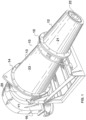
- a cyclone assembly 10 consisting of an inlet assembly 11 and a lower cone and spigot assembly 12, separated by a cyclone body assembly 13, the latter secured to each of the inlet assembly 1 1 and the lower cone and spigot assembly 12 by respective flange abutments 14, 15.
- the inlet assembly has a tangential or cycloidal inlet 16 to, and an in use upper axial outflow from a ceramic-lined inlet portion 20.
- the lower cone and spigot assembly 12 includes a ceramic lined, lower cone 21 defining a separation zone in use for relatively large and/or dense particles of a feed slurry material during a cyclone separation operation, and an underflow outlet spigot 22 via which the separated particles pass in use during discharge.
- the cyclone body assembly 13 includes a steel outer frusto-conical casing 23 having an in use upper inlet flange 24 and a lower underflow flange 25.
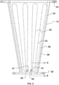
- a wear resistant line assembly 26 comprising closely abutting, isostatically pressed, sintered alumina blocks 27 of both axially tapered and circumferentially curved form, is arranged in serried circumferential rows 30, the joins 31 between adjacent blocks 27 in a row being offset from the joins 31 in the rows axially adjacent.
- a conductive wire insulated by LI NAT EX ® rubber 32 forms an axially aligned zigzag pattern with radiused apices on the outer surface of the liner assembly 26.
- the wire insulated by LlNATEX ® rubber is 5-stranded, multifilament wire wherein each filament comprises 0.38mm brass coated crimped steel, the strands being twisted to form a bundle within the insulation cover.
- the conductive wire 32 is terminated by lead-outs 34 passing through the wall of the casing 23 via ceramic insulators 35.
- the liner assembly 26 is spaced from the casing 23 by a 5-25 mm deep space 36.
- the liner assembly 26, conductive wire 32, lead-outs 34 and insulators 35 are all encapsulated by and secured to the interior wall of the frusta-conical casing 23 by mineral filled epoxy resin encapsulant adhesive filler occupying the space 36.
- LlNATEX ® is a registered trademark of Linatex Limited, a Weir Group PLC affiliate company.
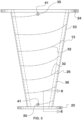
- the conductive wire 32 may be laid in a spiral on the outer surface of the liner assembly 26.
- the apertures 41 are located adjacent the respective flanges 24, 25.
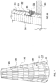
- the wear resistant liner assembly 26 is assembled from the isostatically pressed sintered alumina blocks 27 in the circumferential rows 30 by laying up the blocks 27 about a frusto-conical form, or mandrel 37. The layup is secured against collapse by strategic circumferential tie-wires or tape bands 40.
- the conductive wire 32 is then laid up in either an axially aligned zigzag pattern ( Fig, 2 ) or a circumferential spiral pattern ( Fig. 3 ⁇ on the outer surface of the liner assembly 26, and retained by occasional restraint (not shown).
- the lead-outs 34 are left long at this time.
- the frusto-conical casing 23 has apertures 41 to which are fitted the ceramic insulators 35.
- Each long lead-out 34 is passed through the casing 23 and out through a respective insulator 35.
- the lead outs 34 are continuously eased through the insulators 35 while the casing 23 is lowered over the liner assembly 26.
- a ceramic-bead filled epoxy resin encapsulant adhesive filler is then injected into the 5-25 mm space 36, in order to encapsulate the inner assembly 26, the conductive wire 32, the lead-outs 34 and the insulators 35 and to bond the assembly thereof to the casing 23.
- the long lead-outs 34 may be trimmed and terminated, and the cyclone body assembly 13 assembled by mounting its upper inlet flange 24 and its lower underflow flange 25 to the inlet assembly 11 and to the lower cone and spigot assembly 12, respectively.
- the lower cone and spigot assembly 12 is formed in substantially the same way as described for the body assembly 13 of the cyclone.
- the encapsulant adhesive filler comprises a secondary wear layer.
- the lead-outs 34 each form a terminal between which a continuity tester (in this case, a multimeter) may be connected, in the event that a discontinuity of the conductive wire 32 is detected, a worn state of the primary liner assembly 26 is inferred. Thereafter the operator may program a shut-down in an orderly fashion rather than in response to catastrophic failure.
- the secondary wear liner thus provides a management interval between an indication of failure and shut-down and replacement of the worn assembly.
- Apparatus and methods in in accordance with the foregoing embodiment can reduce the labour required to manufacture cyclone components.
- the internal surface of cyclone component is relatively smoother than the prior art examples since the inner surface is prepared by being laid up on a smooth form or mandrel. This reduces the turbulence generated by the interaction of the outlet surface of the layer of tiles and the circulating fluid within the cyclone chamber.
- the filled epoxy layer may accommodate any 'out-of-round' shape of the fabricated casing while maintaining a regular conical substantially smooth wear surface.
- the "circuit" can easily and rapidly be tested for integrity without disassembly or interruption of the operating process. Excess wear (which is evident if the "circuit” has been broken) warns the operator that the cyclone is operating with access to the secondary wear liner formed by the ceramic-bead filled epoxy, and that scheduled maintenance or replacement of the part is required. Catastrophic failure is therefore avoided with planned maintenance becoming predictable.
- Forming cyclone linings against a form can also accommodate the use of wear elements of varying thickness. This is a very useful alternative given that a vertically oriented cyclone typically wears more aggressively at the in use lower regions of the cyclone. It may therefore be beneficial to be able to use thicker linings in this region of the cyclone. This ability to easily accommodate different lining thickness offers cost and weight savings, which is something not economically achievable using the traditional "tile laying method" on the inside of the casing.
- heating of the casing allows it to expand differentially from the epoxy/liner composite, allowing the word composite to drop out of the taper.
Landscapes
- Chemical & Material Sciences (AREA)
- Chemical Kinetics & Catalysis (AREA)
- Engineering & Computer Science (AREA)
- Mechanical Engineering (AREA)
- Analytical Chemistry (AREA)
- Biochemistry (AREA)
- General Health & Medical Sciences (AREA)
- General Physics & Mathematics (AREA)
- Immunology (AREA)
- Pathology (AREA)
- Physics & Mathematics (AREA)
- Food Science & Technology (AREA)
- Life Sciences & Earth Sciences (AREA)
- Health & Medical Sciences (AREA)
- Cyclones (AREA)
- Cell Separators (AREA)
Claims (17)
- Procédé de formation d'un corps de traitement de minéraux résistant à l'usure, ledit procédé étant caractérisé par les étapes consistant à :assembler des éléments résistants à l'usure (27) pour former une surface résistante à l'usure sensiblement continue contre une surface extérieure d'une forme (37) ;positionner un boîtier (23) sur les éléments résistants à l'usure (31) avec un espace (36) entre eux ;remplir l'espace (36) avec un matériau adhésif durcissable ;laisser durcir le matériau adhésif durcissable afin d'immobiliser les éléments résistants à l'usure (27) par rapport au boîtier (23) ; etretirer la forme (37).
- Procédé selon la revendication 1, dans lequel le corps de traitement de minéraux résistant à l'usure est choisi parmi un ensemble corps de séparateur à cyclone (13) et un ensemble cône inférieur et ergot de séparateur à cyclone (12).
- Procédé selon la revendication 1, dans lequel les éléments résistants à l'usure (31) comprennent un matériau céramique fritté pressé de manière isostatique, éventuellement dans lequel le matériau céramique est l'alumine.
- Procédé selon la revendication 2, dans lequel :(i) les éléments résistants à l'usure (27) comprennent des éléments spécifiquement mis en forme adaptés pour former, en butée étroite, une surface tronconique comprenant ladite surface résistante à l'usure sensiblement continue ; ou(ii) la forme comprend une surface extérieure sensiblement tronconique contre laquelle les éléments résistants à l'usure (27) sont assemblés ; ou(iii) le boîtier (23) est en acier et pourvu d'une ou de plusieurs brides terminales.
- Procédé selon la revendication 1, dans lequel le matériau durcissable est choisi parmi un matériau élastique et un matériau de résine thermodurcissable ; éventuellement dans lequel le matériau durcissable est choisi parmi des matériaux de scellement époxy à charge minérale, la charge minérale comprenant éventuellement des billes céramiques.
- Procédé selon la revendication 1, comportant la fourniture d'un moyen de surveillance dans l'espace entre les éléments résistants à l'usure (27) et le boîtier (23), éventuellement dans lequel :(i) le moyen de surveillance comporte un ou plusieurs transducteurs reliés à une interface externe au boîtier (23) ; ou(ii) le moyen de surveillance comprend un ou plusieurs conducteurs formant chacun un élément de circuit de test de continuité ayant une interface externe au boîtier (23).
- Procédé de formation d'un corps de traitement de minéraux indicatif d'usure, ledit procédé étant caractérisé par les étapes consistant à :fournir un revêtement résistant à l'usure (26) sensiblement continu formé d'éléments résistants à l'usure (27) ;positionner un ou plusieurs éléments de surveillance sur une surface extérieure du revêtement (26) ;positionner un boîtier (23) sur le revêtement résistant à l'usure (26) avec un espace (36) entre eux ;fournir une sortie (34) de chaque élément de surveillance à une interface externe au boîtier (23) ;remplir l'espace (36) avec un matériau adhésif durcissable ; etlaisser durcir le matériau adhésif durcissable.
- Procédé selon la revendication 7, dans lequel le corps de traitement de minéraux résistant à l'usure est choisi parmi un ensemble corps de séparateur à cyclone et un ensemble cône inférieur et ergot de séparateur à cyclone (12).
- Procédé selon la revendication 8, dans lequel le revêtement résistant à l'usure est formé d'éléments résistants à l'usure (27), éventuellement dans lequel les éléments résistants à l'usure (27) comprennent :(i) de l'alumine frittée pressée de manière isostatique ; ou(ii) des éléments spécifiquement mis en forme adaptés pour former en assemblage une surface d'usure tronconique.
- Procédé selon la revendication 7, dans lequel les éléments de surveillance :(a) comportent un ou plusieurs transducteurs reliés à une interface externe à l'élément de corps ; ou(b) comprennent un ou plusieurs conducteurs formant chacun un élément de circuit de test de continuité, éventuellement dans lequel le conducteur ou les conducteurs sont :(i) enroulés en spirale autour de la surface extérieure ; ou(ii) agencés selon un motif choisi parmi un motif généralement en zigzag, sinusoïdal ou en spirale circonférentielle.
- Procédé selon la revendication 8, dans lequel les éléments de surveillance comprennent un ou plusieurs conducteurs formant chacun un dispositif de test de continuité, chacun agencé selon un motif en zigzag ou sinusoïdal ayant un espacement des sommets du conducteur au niveau d'une partie de base tronconique du corps qui est plus grand que l'espacement vers une partie de troncature supérieure du corps, éventuellement dans lequel au moins deux conducteurs en zigzag, sinusoïdaux ou en spirale circonférentielle axialement entrelacés sont présents.
- Procédé selon la revendication 7, dans lequel :(i) les sorties comprennent des fils isolés passant à travers des ouvertures à travers une partie de paroi latérale du boîtier (23) ; ou(ii) l'interface est choisie parmi des bornes électriques, des bagues collectrices et des dispositifs RFID adaptés pour être reliés à l'élément de surveillance.
- Procédé de formation d'un composant séparateur à cyclone indicatif d'usure, ledit procédé étant caractérisé par les étapes consistant à :fournir un revêtement (26) de composant cyclone résistant à l'usure sensiblement tronconique formé d'éléments résistants à l'usure (27) ;positionner un ou plusieurs fils conducteurs sur une surface extérieure du revêtement (26) ;positionner un boîtier (23) de séparateur à cyclone sur le revêtement (26) de cyclone, une surface intérieure du boîtier (23) et le revêtement (26) de composant cyclone définissant un espace (36) entre eux ;fournir une pluralité de sorties (34) de chaque conducteur jusqu'à l'extérieur du boîtier (23) de séparateur à cyclone ;remplir l'espace (36) avec un matériau adhésif durcissable pour immobiliser le revêtement (26) de cyclone par rapport au boîtier (23) de séparateur à cyclone ; etlaisser durcir le matériau adhésif durcissable.
- Corps de traitement de minéraux résistant à l'usure, caractérisé en ce que le corps de traitement de minéraux résistant à l'usure comporte :une surface intérieure sensiblement lisse, résistante à l'usure, formée d'une pluralité d'éléments résistants à l'usure (27) sensiblement en butée ; etun boîtier (23) immobilisé sur les éléments résistants à l'usure (27) et les supportant par un matériau adhésif durcissable remplissant un espace (36) entre le boîtier (23) et les éléments résistants à l'usure (27) dans l'ensemble.
- Corps de séparateur à cyclone indicatif d'usure, caractérisé en ce que le corps de traitement de minéraux résistant à l'usure comporte :un revêtement (26) de cyclone résistant à l'usure sensiblement tronconique formé d'une pluralité d'éléments résistants à l'usure (27) ;un ou plusieurs fils conducteurs positionnés sur une surface extérieure du revêtement (26) ; etun boîtier de séparateur à cyclone ayant une pluralité de sorties (34) à partir de chaque conducteur et positionné et immobilisé sur le revêtement de cyclone par un matériau adhésif durcissable remplissant un espace (36) entre eux.
- Corps de traitement de minéraux résistant à l'usure lorsqu'il est produit par un procédé de l'une quelconque des revendications 1 à 6.
- Corps de traitement de minéraux indicatif d'usure lorsqu'il est produit par un procédé de l'une quelconque des revendications 7 à 12.
Applications Claiming Priority (2)
| Application Number | Priority Date | Filing Date | Title |
|---|---|---|---|
| AU2013902999A AU2013902999A0 (en) | 2013-08-09 | Cyclone separator apparatus and methods of production | |
| PCT/AU2014/050176 WO2015017902A1 (fr) | 2013-08-09 | 2014-08-08 | Appareil séparateur à cyclone et procédés de production |
Publications (4)
| Publication Number | Publication Date |
|---|---|
| EP3030423A1 EP3030423A1 (fr) | 2016-06-15 |
| EP3030423A4 EP3030423A4 (fr) | 2017-10-18 |
| EP3030423B1 true EP3030423B1 (fr) | 2024-07-17 |
| EP3030423C0 EP3030423C0 (fr) | 2024-07-17 |
Family
ID=52460436
Family Applications (1)
| Application Number | Title | Priority Date | Filing Date |
|---|---|---|---|
| EP14834531.7A Active EP3030423B1 (fr) | 2013-08-09 | 2014-08-08 | Appareil séparateur à cyclone et procédés de production |
Country Status (8)
| Country | Link |
|---|---|
| US (2) | US10159989B2 (fr) |
| EP (1) | EP3030423B1 (fr) |
| CN (1) | CN105636786B (fr) |
| AP (1) | AP2016009028A0 (fr) |
| AU (2) | AU2014305660B2 (fr) |
| EA (2) | EA036609B1 (fr) |
| WO (1) | WO2015017902A1 (fr) |
| ZA (1) | ZA201902851B (fr) |
Families Citing this family (10)
| Publication number | Priority date | Publication date | Assignee | Title |
|---|---|---|---|---|
| WO2015017902A1 (fr) * | 2013-08-09 | 2015-02-12 | Weir Minerals Australia Ltd | Appareil séparateur à cyclone et procédés de production |
| JP6804200B2 (ja) * | 2016-02-08 | 2020-12-23 | 三菱パワー株式会社 | スラグサイクロン、ガス化設備、ガス化複合発電設備、スラグサイクロンの運転方法およびスラグサイクロンのメンテナンス方法 |
| BE1024631B9 (nl) * | 2016-10-11 | 2019-05-13 | Atlas Copco Airpower Nv | Vloeistofafscheider |
| WO2019180549A1 (fr) * | 2018-03-21 | 2019-09-26 | Weir Canada, Inc. | Appareil d'égalisation d'usure pour cyclones |
| PE20210267A1 (es) * | 2018-06-18 | 2021-02-10 | Compania Electro Metalurgica S A | Conjunto de revestimiento mejorado para molino de mineral |
| CN109332021A (zh) * | 2018-11-25 | 2019-02-15 | 威海市海王旋流器有限公司 | 一种带寿命报警功能的旋流器有机材料内衬结构 |
| CN111060356B (zh) * | 2020-01-07 | 2024-10-11 | 中国地质科学院探矿工艺研究所 | 一种可替换耐磨内衬的旋流取样器 |
| DE102020103756B4 (de) | 2020-01-16 | 2024-10-17 | Akw Apparate + Verfahren Gmbh | Vorrichtung zur Verschleißkontrolle an Hydrozyklon-Apex- oder Unterlaufdüsen |
| CN119031983A (zh) * | 2022-04-25 | 2024-11-26 | 福伊特专利有限公司 | 用于清洁纤维悬浮液的水力旋流器 |
| CN115254467A (zh) * | 2022-06-24 | 2022-11-01 | 唐山助纲炉料有限公司 | 耐热耐磨的炉内气固分离布料器 |
Family Cites Families (86)
| Publication number | Priority date | Publication date | Assignee | Title |
|---|---|---|---|---|
| US2792075A (en) * | 1954-06-22 | 1957-05-14 | Thermix Corp | Apparatus for separating suspended mist particles from gases |
| US2711226A (en) * | 1954-07-12 | 1955-06-21 | Research Corp | Electrified centrifugal gas cleaning device |
| US2974684A (en) * | 1955-11-25 | 1961-03-14 | Bauer Bros Co | Reinforced molded cone |
| US3087645A (en) * | 1958-11-14 | 1963-04-30 | Phillips Petroleum Co | Method for forming liners for vessels |
| US3273320A (en) * | 1963-07-15 | 1966-09-20 | Exxon Research Engineering Co | Cyclone separator for high temperature operations |
| US3374885A (en) * | 1963-10-15 | 1968-03-26 | Unifab Inc | Method and apparatus for beneficiating minerals |
| US3331193A (en) * | 1964-03-23 | 1967-07-18 | Bauer Bros Co | Cyclonic separator |
| US3327456A (en) * | 1964-04-30 | 1967-06-27 | Exxon Research Engineering Co | High temperature cyclone |
| US3243043A (en) * | 1964-12-07 | 1966-03-29 | Thompson Lee Lavere | Method of controlling the discharge of solids from an orifice of a centrifugal separator |
| GB1110284A (en) * | 1965-06-22 | 1968-04-18 | Nat Res Dev | Improvements in or relating to the continuous analysis of the solid component of a slurry |
| US3443368A (en) * | 1966-07-26 | 1969-05-13 | Shell Oil Co | Tubular centrifugal separators |
| US3543325A (en) * | 1967-12-22 | 1970-12-01 | Jl Products Inc | Vacuum cleaning system with waste collection remote from suction fan |
| NL140039B (nl) * | 1970-07-01 | 1973-10-15 | Vredestein Rubber | Pomphuis voor een centrifugaalpomp, in het bijzonder zand- of grintpomp. |
| US3895150A (en) * | 1971-08-02 | 1975-07-15 | Norton Co | Wear resistant aluminous ceramic articles and process for making the same |
| US3902601A (en) * | 1974-03-14 | 1975-09-02 | Townley Ind Plastics Inc | One piece cyclone cone |
| US4010011A (en) * | 1975-04-30 | 1977-03-01 | The United States Of America As Represented By The Secretary Of The Army | Electro-inertial air cleaner |
| GB1547610A (en) * | 1975-05-09 | 1979-06-20 | Skega Ab | Wear liners for abrasive-material handling equipment |
| US4004898A (en) * | 1976-01-30 | 1977-01-25 | Emtrol Corporation | Cyclone separator gas tube heat dissipator |
| US4317716A (en) * | 1979-01-11 | 1982-03-02 | Liller Delbert I | Vortex finder and sleeve kit |
| US4224143A (en) * | 1979-01-11 | 1980-09-23 | Liller Delbert I | Construction of shallow dish with tapered orifice for streamlined flow cyclone washing of crushed coal |
| DE3007147A1 (de) * | 1980-02-26 | 1981-09-03 | Schmelzbasaltwerk Kalenborn - Dr.-Ing. Mauritz KG, 5461 Vettelschoß | Verfahren zum verlegen von in zementmoertel wenig haftenden platten |
| US4623458A (en) * | 1983-07-19 | 1986-11-18 | Hakola Gordon R | Quick release expendable apex apparatus with bonded liner |
| US4539105A (en) * | 1983-11-17 | 1985-09-03 | Wilbanks International, Inc. | Cyclone separator having abrasion resistant cone covered by a plastic sleeve with flexible seal regions |
| US4646001A (en) | 1983-11-21 | 1987-02-24 | Morganite Electrical Carbon Limited | Resistive wear sensors |
| US4601867A (en) * | 1984-07-03 | 1986-07-22 | General Motors Corporation | Method of making cast-to-size epoxy tools for stamping sheet metal panels |
| SU1223998A1 (ru) | 1984-11-05 | 1986-04-15 | Дзержинский филиал Ленинградского научно-исследовательского и конструкторского института химического машиностроения | Гидроциклон |
| US5016474A (en) * | 1985-02-19 | 1991-05-21 | J. W. Harley Inc. | Ultrasonic transducer |
| US4746337A (en) * | 1987-07-06 | 1988-05-24 | Foster Wheeler Energy Corporation | Cyclone separator having water-steam cooled walls |
| US4944250A (en) * | 1989-03-30 | 1990-07-31 | Foster Wheeler Energy Corporation | Cyclone separator including a hopper formed by water-steam cooled walls |
| US4961761A (en) * | 1989-08-18 | 1990-10-09 | Foster Wheeler Energy Corporation | Cyclone separator wall refractory material system |
| US5116394A (en) * | 1991-03-25 | 1992-05-26 | Foster Wheeler Energy Corporation | Cyclone separator roof |
| ES2130155T3 (es) * | 1991-03-25 | 1999-07-01 | Ecc Int Ltd | Cargas minerales. |
| DE4236895A1 (de) | 1992-10-31 | 1994-05-05 | Maury Hans Dietmar | Tauchrohr für einen Fliehkraftabscheider (Zyklon) |
| DE4308272C1 (de) * | 1993-03-16 | 1994-06-09 | Mannesmann Kienzle Gmbh | Sensorelement für einen mehrstufigen Verschleißgeber, insbesondere für Bremsbeläge |
| EP0706612A4 (fr) * | 1993-06-28 | 1997-03-19 | Thomas C Hudson Jr | Panneau ceramique de transfert mecanique |
| US5869008A (en) * | 1996-05-08 | 1999-02-09 | Shell Oil Company | Apparatus and method for the separation and stripping of fluid catalyst cracking particles from gaseous hydrocarbons |
| US6267803B1 (en) * | 1997-06-26 | 2001-07-31 | International Paper Company | Abrasive wear barrier |
| DE19825206A1 (de) * | 1998-06-05 | 1999-12-09 | Kloeckner Humboldt Wedag | Zyklonabscheider |
| IL125335A (en) * | 1998-07-14 | 2003-10-31 | Odis Irrigation Equipment Ltd | Hydrocyclone separator |
| CA2304266A1 (fr) * | 1999-04-02 | 2000-10-02 | Norman L. Arrison | Appareil et procede permettant de separer les fluides et les particules |
| AUPQ040599A0 (en) | 1999-05-18 | 1999-06-10 | Cmi Malco Pty Ltd | An erosion detector |
| JP2001029843A (ja) * | 1999-07-23 | 2001-02-06 | Ishikawajima Harima Heavy Ind Co Ltd | 粒子分級装置 |
| US7293657B1 (en) * | 2000-05-02 | 2007-11-13 | Krebs International | Hydrocyclone and method for liquid-solid separation and classification |
| ES2220618T3 (es) * | 2000-05-12 | 2004-12-16 | Khd Humboldt Wedag Ag | Elemento de montaje empotrado sometido al calor y al desgaste, especialmente segmento de un tubo de inmersion ciclonico. |
| AU2002223582B2 (en) * | 2000-10-04 | 2004-06-03 | Shell Internationale Research Maatschappij B.V. | Process for providing a surface with a fire-proof and/or wear resistant lining |
| US6596170B2 (en) * | 2000-11-24 | 2003-07-22 | Wlodzimierz Jon Tuszko | Long free vortex cylindrical telescopic separation chamber cyclone apparatus |
| US6758993B2 (en) * | 2002-04-17 | 2004-07-06 | Delphi Technologies, Inc. | System and method for minimizing cure-induced residual stress in an epoxy impregnated ignition coil |
| US6686752B1 (en) | 2002-06-19 | 2004-02-03 | Fisher-Klosterman, Inc. | Wear indicator for refractory linings |
| JP2004027949A (ja) * | 2002-06-25 | 2004-01-29 | Yukio Kinoshita | 高効率排気ガス処理システム |
| DE20219551U1 (de) * | 2002-12-16 | 2004-04-29 | Westfalia Separator Ag | Zentrifuge, insbesondere Separator, mit Feststoff-Austrittsdüsen |
| US7011219B2 (en) * | 2003-07-02 | 2006-03-14 | Petreco International, Ltd. | Erosion-resistant hydrocyclone liner |
| US7141523B2 (en) * | 2003-09-18 | 2006-11-28 | 3M Innovative Properties Company | Ceramics comprising Al2O3, REO, ZrO2 and/or HfO2, and Nb2O5 and/or Ta2O5 and methods of making the same |
| US6962434B2 (en) | 2003-09-25 | 2005-11-08 | Kerr-Mcgee Chemical, Llc | Liner wear detection |
| US7762402B2 (en) * | 2003-11-19 | 2010-07-27 | Hakola Gordon R | Cyclone with in-situ replaceable liner system and method for accomplishing same |
| GB2411369B (en) * | 2004-02-27 | 2007-02-14 | Dynamic Proc Solutions Ltd | Cyclone assembly and method for increasing or decreasing flow capacity of a cyclone separator in use |
| CN2678775Y (zh) * | 2004-03-16 | 2005-02-16 | 张启峰 | 组合型高温旋风分离器 |
| US7182803B2 (en) * | 2004-06-16 | 2007-02-27 | United Technologies Corporation | Solids multi-clone separator |
| WO2006072123A1 (fr) * | 2005-01-10 | 2006-07-13 | Wear Applications & Management Services Pty Ltd | Système de surveillance d’usure |
| CN100490983C (zh) | 2005-02-03 | 2009-05-27 | 西安建筑科技大学 | 三元复合材料内衬耐磨旋流器的制备工艺 |
| GB0515266D0 (en) * | 2005-07-26 | 2005-08-31 | Domnick Hunter Ltd | Separator assembly |
| CA2539048A1 (fr) * | 2006-03-09 | 2007-09-09 | Dennis Slater | Systeme de mesure du degre d'usure d'un broyeur |
| DE102006024820A1 (de) * | 2006-05-29 | 2007-12-13 | Mahle International Gmbh | Einrichtung zur Trennung eines Gas-Flüssigkeitsgemisches, insbesondere bei der Entlüftung eines Kurbelgehäuses eines Verbrennungsmotors |
| US20080041994A1 (en) * | 2006-06-23 | 2008-02-21 | Hall David R | A Replaceable Wear Liner with Super Hard Composite Inserts |
| EE05544B1 (et) * | 2007-09-05 | 2012-06-15 | Aktsiaselts Narva ?Litehas | Tolmu eraldamise kamber auru-gaasisegust tahkete osakeste eraldamiseks |
| DE102008011744A1 (de) * | 2008-02-28 | 2009-09-03 | Voith Patent Gmbh | Verfahren zum Entfernen von Schwerteilen aus einer Fasersuspension unter Verwendung eines Hydrozyklons sowie Vorrichtungen zur Durchführung des Verfahrens |
| US8034143B2 (en) * | 2008-03-18 | 2011-10-11 | Uti Limited Partnership | Cyclone |
| US8245532B2 (en) * | 2008-05-15 | 2012-08-21 | Concepts Eti, Inc. | Semi-closed air-cycle refrigeration system and a positive-pressure snow removal cyclone separator therefor |
| US8679214B2 (en) * | 2009-07-10 | 2014-03-25 | Alfa Laval Corporate Ab | Gas cleaning separator |
| JPWO2011058978A1 (ja) * | 2009-11-10 | 2013-04-04 | 株式会社フジクラ | 配線基板の製造方法 |
| DE102010007936A1 (de) * | 2010-02-12 | 2011-08-18 | Outotec Oyj | Tauchrohrabtragung und Zyklon hiermit |
| US8157895B2 (en) * | 2010-05-04 | 2012-04-17 | Kellogg Brown & Root Llc | System for reducing head space in a pressure cyclone |
| US9267636B2 (en) * | 2010-05-07 | 2016-02-23 | 1876255 Ontario Limited | Protective liner with wear detection |
| US9022231B1 (en) * | 2010-05-26 | 2015-05-05 | Claude Laval Corporation | Centrifugal separator with filter rod |
| EP2457646A1 (fr) * | 2010-11-26 | 2012-05-30 | Enefit Outotec Technology Oü | Séparateur pour séparer des particules solides d'un mélange de gaz et de vapeur |
| CN102615004A (zh) * | 2011-01-30 | 2012-08-01 | 姜堰市三佐电力设备制造有限公司 | 旋流器过流构件表面耐磨结构 |
| WO2012116416A1 (fr) * | 2011-03-03 | 2012-09-07 | Bradken Resources Pty Limited | Procédé, système et appareil pour applications associées à une indication d'usure |
| CN202199437U (zh) | 2011-09-01 | 2012-04-25 | 青海大地环境工程技术有限公司 | 旋风分离器和气固分离装置 |
| US8945399B2 (en) * | 2011-11-29 | 2015-02-03 | Taper-Lok Corporation | Systems and methods for separating sand from oil |
| US9744490B1 (en) * | 2012-04-06 | 2017-08-29 | Enertechnix, Inc. | Trapped vortex particle-to-vapor converter |
| JP6006523B2 (ja) * | 2012-04-27 | 2016-10-12 | 新光電気工業株式会社 | 接続構造体、配線基板ユニット、電子回路部品ユニット、及び電子装置 |
| CN202909835U (zh) | 2012-11-24 | 2013-05-01 | 闫海群 | 新型耐磨旋流器 |
| WO2015017902A1 (fr) * | 2013-08-09 | 2015-02-12 | Weir Minerals Australia Ltd | Appareil séparateur à cyclone et procédés de production |
| US20150068975A1 (en) * | 2013-09-10 | 2015-03-12 | Energy Recovery, Inc. | Wear-resistant liner system and method |
| FI126040B (en) * | 2014-07-09 | 2016-06-15 | Amec Foster Wheeler En Oy | Particle separator and fluidized bed reactor that can be connected to a fluidized bed reactor |
| AU2015321378B2 (en) * | 2014-09-23 | 2020-03-05 | Polycorp Ltd. | Discharge end wall inserts |
| KR101618338B1 (ko) * | 2015-07-09 | 2016-05-04 | 한국과학기술연구원 | 수소정화장치 |
-
2014
- 2014-08-08 WO PCT/AU2014/050176 patent/WO2015017902A1/fr not_active Ceased
- 2014-08-08 EA EA201891763A patent/EA036609B1/ru not_active IP Right Cessation
- 2014-08-08 AU AU2014305660A patent/AU2014305660B2/en active Active
- 2014-08-08 US US14/910,379 patent/US10159989B2/en active Active
- 2014-08-08 CN CN201480055284.2A patent/CN105636786B/zh active Active
- 2014-08-08 EA EA201690361A patent/EA032168B1/ru not_active IP Right Cessation
- 2014-08-08 EP EP14834531.7A patent/EP3030423B1/fr active Active
- 2014-08-08 AP AP2016009028A patent/AP2016009028A0/en unknown
-
2018
- 2018-01-18 AU AU2018200426A patent/AU2018200426B2/en active Active
- 2018-12-11 US US16/216,861 patent/US11135603B2/en active Active
-
2019
- 2019-05-07 ZA ZA2019/02851A patent/ZA201902851B/en unknown
Also Published As
| Publication number | Publication date |
|---|---|
| US10159989B2 (en) | 2018-12-25 |
| US11135603B2 (en) | 2021-10-05 |
| CN105636786B (zh) | 2018-05-18 |
| AU2018200426A1 (en) | 2018-02-08 |
| AU2014305660A1 (en) | 2016-02-25 |
| AP2016009028A0 (en) | 2016-02-29 |
| US20190105665A1 (en) | 2019-04-11 |
| EA201891763A1 (ru) | 2019-01-31 |
| EA201690361A1 (ru) | 2016-08-31 |
| ZA201902851B (en) | 2025-05-28 |
| EA032168B1 (ru) | 2019-04-30 |
| EP3030423A4 (fr) | 2017-10-18 |
| AU2018200426B2 (en) | 2018-10-04 |
| EA036609B1 (ru) | 2020-11-30 |
| US20160184837A1 (en) | 2016-06-30 |
| EP3030423C0 (fr) | 2024-07-17 |
| WO2015017902A1 (fr) | 2015-02-12 |
| EP3030423A1 (fr) | 2016-06-15 |
| AU2014305660B2 (en) | 2018-02-22 |
| CN105636786A (zh) | 2016-06-01 |
Similar Documents
| Publication | Publication Date | Title |
|---|---|---|
| US11135603B2 (en) | Cyclone separator apparatus and methods of production | |
| CN102822444B (zh) | 用于将砂石颗粒分离的耐磨损的分离装置 | |
| US8561694B2 (en) | Monitoring downhole production flow in an oil or gas | |
| CN108778517B (zh) | 受控湍流分解流 | |
| US5319671A (en) | Prewarning device for induction melting furnace | |
| EP1676073B1 (fr) | Detection de l'usure des chemises | |
| WO2000070326A1 (fr) | Detection de l'erosion peripherique d'un conduit | |
| US6686752B1 (en) | Wear indicator for refractory linings | |
| EP3206800B1 (fr) | Plaque de blindage, procédé de fabrication d'une plaque de blindage et un broyeur | |
| AU772972B2 (en) | Detection of circumferential erosion of a conduit | |
| CN113557093B (zh) | 用于检测柱状状态的形成的水力旋流器 | |
| EP3604734A1 (fr) | Dispositif de séparation et utilisation d'un dispositif de séparation | |
| CN206464099U (zh) | 一种临界流速喷嘴 | |
| JPH11287607A (ja) | ライニング構造物及びその摩耗検知方法 | |
| CN201815387U (zh) | 用于螺旋推料器布料腔的耐磨条 | |
| CN206190293U (zh) | 安装有传感器的加固式隧道结构 | |
| CN222578866U (zh) | 一种带有投料结构的棕刚玉生产用电弧熔炼炉 | |
| EP1685347B1 (fr) | Procédé de fabrication d'un joint de revetement et un tuyau ou récipient revetu | |
| EA041049B1 (ru) | Гидроциклон для обнаружения формирования состояния уплотнения потока | |
| ITMI961772A1 (it) | Procedimento per la produzione di un filo diamantato per impiego nel taglio di metalli lapidei e filo diamantato con esso prodotto | |
| JP7014767B2 (ja) | ライニング摩耗検出システムを有する電気誘導炉 | |
| CN102397822A (zh) | 用于螺旋推料器布料腔的耐磨条 |
Legal Events
| Date | Code | Title | Description |
|---|---|---|---|
| PUAI | Public reference made under article 153(3) epc to a published international application that has entered the european phase |
Free format text: ORIGINAL CODE: 0009012 |
|
| 17P | Request for examination filed |
Effective date: 20160202 |
|
| AK | Designated contracting states |
Kind code of ref document: A1 Designated state(s): AL AT BE BG CH CY CZ DE DK EE ES FI FR GB GR HR HU IE IS IT LI LT LU LV MC MK MT NL NO PL PT RO RS SE SI SK SM TR |
|
| AX | Request for extension of the european patent |
Extension state: BA ME |
|
| DAX | Request for extension of the european patent (deleted) | ||
| RIC1 | Information provided on ipc code assigned before grant |
Ipc: G01N 3/56 20060101ALI20170426BHEP Ipc: B02C 17/22 20060101ALI20170426BHEP Ipc: B32B 37/12 20060101AFI20170426BHEP |
|
| A4 | Supplementary search report drawn up and despatched |
Effective date: 20170915 |
|
| RIC1 | Information provided on ipc code assigned before grant |
Ipc: B32B 37/12 20060101AFI20170911BHEP Ipc: B02C 17/22 20060101ALI20170911BHEP Ipc: G01N 3/56 20060101ALI20170911BHEP |
|
| STAA | Information on the status of an ep patent application or granted ep patent |
Free format text: STATUS: EXAMINATION IS IN PROGRESS |
|
| 17Q | First examination report despatched |
Effective date: 20191106 |
|
| REG | Reference to a national code |
Ref legal event code: R079 Free format text: PREVIOUS MAIN CLASS: B32B0037120000 Ipc: B04C0005085000 Ref country code: DE Ref legal event code: R079 Ref document number: 602014090525 Country of ref document: DE Free format text: PREVIOUS MAIN CLASS: B32B0037120000 Ipc: B04C0005085000 |
|
| RIC1 | Information provided on ipc code assigned before grant |
Ipc: B04C 5/085 20060101AFI20240319BHEP |
|
| GRAP | Despatch of communication of intention to grant a patent |
Free format text: ORIGINAL CODE: EPIDOSNIGR1 |
|
| STAA | Information on the status of an ep patent application or granted ep patent |
Free format text: STATUS: GRANT OF PATENT IS INTENDED |
|
| INTG | Intention to grant announced |
Effective date: 20240429 |
|
| GRAS | Grant fee paid |
Free format text: ORIGINAL CODE: EPIDOSNIGR3 |
|
| GRAA | (expected) grant |
Free format text: ORIGINAL CODE: 0009210 |
|
| STAA | Information on the status of an ep patent application or granted ep patent |
Free format text: STATUS: THE PATENT HAS BEEN GRANTED |
|
| AK | Designated contracting states |
Kind code of ref document: B1 Designated state(s): AL AT BE BG CH CY CZ DE DK EE ES FI FR GB GR HR HU IE IS IT LI LT LU LV MC MK MT NL NO PL PT RO RS SE SI SK SM TR |
|
| REG | Reference to a national code |
Ref country code: GB Ref legal event code: FG4D |
|
| REG | Reference to a national code |
Ref country code: CH Ref legal event code: EP |
|
| REG | Reference to a national code |
Ref country code: DE Ref legal event code: R096 Ref document number: 602014090525 Country of ref document: DE |
|
| REG | Reference to a national code |
Ref country code: IE Ref legal event code: FG4D |
|
| U01 | Request for unitary effect filed |
Effective date: 20240717 |
|
| U07 | Unitary effect registered |
Designated state(s): AT BE BG DE DK EE FI FR IT LT LU LV MT NL PT SE SI Effective date: 20240723 |
|
| U20 | Renewal fee for the european patent with unitary effect paid |
Year of fee payment: 11 Effective date: 20240827 |
|
| PG25 | Lapsed in a contracting state [announced via postgrant information from national office to epo] |
Ref country code: NO Free format text: LAPSE BECAUSE OF FAILURE TO SUBMIT A TRANSLATION OF THE DESCRIPTION OR TO PAY THE FEE WITHIN THE PRESCRIBED TIME-LIMIT Effective date: 20241017 |
|
| PG25 | Lapsed in a contracting state [announced via postgrant information from national office to epo] |
Ref country code: PL Free format text: LAPSE BECAUSE OF FAILURE TO SUBMIT A TRANSLATION OF THE DESCRIPTION OR TO PAY THE FEE WITHIN THE PRESCRIBED TIME-LIMIT Effective date: 20240717 Ref country code: GR Free format text: LAPSE BECAUSE OF FAILURE TO SUBMIT A TRANSLATION OF THE DESCRIPTION OR TO PAY THE FEE WITHIN THE PRESCRIBED TIME-LIMIT Effective date: 20241018 |
|
| PG25 | Lapsed in a contracting state [announced via postgrant information from national office to epo] |
Ref country code: IS Free format text: LAPSE BECAUSE OF FAILURE TO SUBMIT A TRANSLATION OF THE DESCRIPTION OR TO PAY THE FEE WITHIN THE PRESCRIBED TIME-LIMIT Effective date: 20241117 |
|
| PG25 | Lapsed in a contracting state [announced via postgrant information from national office to epo] |
Ref country code: HR Free format text: LAPSE BECAUSE OF FAILURE TO SUBMIT A TRANSLATION OF THE DESCRIPTION OR TO PAY THE FEE WITHIN THE PRESCRIBED TIME-LIMIT Effective date: 20240717 |
|
| PG25 | Lapsed in a contracting state [announced via postgrant information from national office to epo] |
Ref country code: ES Free format text: LAPSE BECAUSE OF FAILURE TO SUBMIT A TRANSLATION OF THE DESCRIPTION OR TO PAY THE FEE WITHIN THE PRESCRIBED TIME-LIMIT Effective date: 20240717 Ref country code: RS Free format text: LAPSE BECAUSE OF FAILURE TO SUBMIT A TRANSLATION OF THE DESCRIPTION OR TO PAY THE FEE WITHIN THE PRESCRIBED TIME-LIMIT Effective date: 20241017 |
|
| PG25 | Lapsed in a contracting state [announced via postgrant information from national office to epo] |
Ref country code: RS Free format text: LAPSE BECAUSE OF FAILURE TO SUBMIT A TRANSLATION OF THE DESCRIPTION OR TO PAY THE FEE WITHIN THE PRESCRIBED TIME-LIMIT Effective date: 20241017 Ref country code: PL Free format text: LAPSE BECAUSE OF FAILURE TO SUBMIT A TRANSLATION OF THE DESCRIPTION OR TO PAY THE FEE WITHIN THE PRESCRIBED TIME-LIMIT Effective date: 20240717 Ref country code: NO Free format text: LAPSE BECAUSE OF FAILURE TO SUBMIT A TRANSLATION OF THE DESCRIPTION OR TO PAY THE FEE WITHIN THE PRESCRIBED TIME-LIMIT Effective date: 20241017 Ref country code: IS Free format text: LAPSE BECAUSE OF FAILURE TO SUBMIT A TRANSLATION OF THE DESCRIPTION OR TO PAY THE FEE WITHIN THE PRESCRIBED TIME-LIMIT Effective date: 20241117 Ref country code: HR Free format text: LAPSE BECAUSE OF FAILURE TO SUBMIT A TRANSLATION OF THE DESCRIPTION OR TO PAY THE FEE WITHIN THE PRESCRIBED TIME-LIMIT Effective date: 20240717 Ref country code: GR Free format text: LAPSE BECAUSE OF FAILURE TO SUBMIT A TRANSLATION OF THE DESCRIPTION OR TO PAY THE FEE WITHIN THE PRESCRIBED TIME-LIMIT Effective date: 20241018 Ref country code: ES Free format text: LAPSE BECAUSE OF FAILURE TO SUBMIT A TRANSLATION OF THE DESCRIPTION OR TO PAY THE FEE WITHIN THE PRESCRIBED TIME-LIMIT Effective date: 20240717 |
|
| REG | Reference to a national code |
Ref country code: CH Ref legal event code: PL |
|
| PG25 | Lapsed in a contracting state [announced via postgrant information from national office to epo] |
Ref country code: SM Free format text: LAPSE BECAUSE OF FAILURE TO SUBMIT A TRANSLATION OF THE DESCRIPTION OR TO PAY THE FEE WITHIN THE PRESCRIBED TIME-LIMIT Effective date: 20240717 |
|
| PG25 | Lapsed in a contracting state [announced via postgrant information from national office to epo] |
Ref country code: MC Free format text: LAPSE BECAUSE OF FAILURE TO SUBMIT A TRANSLATION OF THE DESCRIPTION OR TO PAY THE FEE WITHIN THE PRESCRIBED TIME-LIMIT Effective date: 20240717 Ref country code: CH Free format text: LAPSE BECAUSE OF NON-PAYMENT OF DUE FEES Effective date: 20240831 |
|
| PG25 | Lapsed in a contracting state [announced via postgrant information from national office to epo] |
Ref country code: CZ Free format text: LAPSE BECAUSE OF FAILURE TO SUBMIT A TRANSLATION OF THE DESCRIPTION OR TO PAY THE FEE WITHIN THE PRESCRIBED TIME-LIMIT Effective date: 20240717 |
|
| PG25 | Lapsed in a contracting state [announced via postgrant information from national office to epo] |
Ref country code: SK Free format text: LAPSE BECAUSE OF FAILURE TO SUBMIT A TRANSLATION OF THE DESCRIPTION OR TO PAY THE FEE WITHIN THE PRESCRIBED TIME-LIMIT Effective date: 20240717 |
|
| PLBE | No opposition filed within time limit |
Free format text: ORIGINAL CODE: 0009261 |
|
| STAA | Information on the status of an ep patent application or granted ep patent |
Free format text: STATUS: NO OPPOSITION FILED WITHIN TIME LIMIT |
|
| 26N | No opposition filed |
Effective date: 20250422 |
|
| GBPC | Gb: european patent ceased through non-payment of renewal fee |
Effective date: 20241017 |
|
| PG25 | Lapsed in a contracting state [announced via postgrant information from national office to epo] |
Ref country code: GB Free format text: LAPSE BECAUSE OF NON-PAYMENT OF DUE FEES Effective date: 20241017 |
|
| PG25 | Lapsed in a contracting state [announced via postgrant information from national office to epo] |
Ref country code: IE Free format text: LAPSE BECAUSE OF NON-PAYMENT OF DUE FEES Effective date: 20240808 |
|
| U20 | Renewal fee for the european patent with unitary effect paid |
Year of fee payment: 12 Effective date: 20250827 |
|
| PG25 | Lapsed in a contracting state [announced via postgrant information from national office to epo] |
Ref country code: RO Free format text: LAPSE BECAUSE OF FAILURE TO SUBMIT A TRANSLATION OF THE DESCRIPTION OR TO PAY THE FEE WITHIN THE PRESCRIBED TIME-LIMIT Effective date: 20240717 |
|
| PG25 | Lapsed in a contracting state [announced via postgrant information from national office to epo] |
Ref country code: CY Free format text: LAPSE BECAUSE OF FAILURE TO SUBMIT A TRANSLATION OF THE DESCRIPTION OR TO PAY THE FEE WITHIN THE PRESCRIBED TIME-LIMIT; INVALID AB INITIO Effective date: 20140808 |
|
| PG25 | Lapsed in a contracting state [announced via postgrant information from national office to epo] |
Ref country code: HU Free format text: LAPSE BECAUSE OF FAILURE TO SUBMIT A TRANSLATION OF THE DESCRIPTION OR TO PAY THE FEE WITHIN THE PRESCRIBED TIME-LIMIT; INVALID AB INITIO Effective date: 20140808 |