EP3030471B1 - Chariot transporteur pliable - Google Patents
Chariot transporteur pliable Download PDFInfo
- Publication number
- EP3030471B1 EP3030471B1 EP14750200.9A EP14750200A EP3030471B1 EP 3030471 B1 EP3030471 B1 EP 3030471B1 EP 14750200 A EP14750200 A EP 14750200A EP 3030471 B1 EP3030471 B1 EP 3030471B1
- Authority
- EP
- European Patent Office
- Prior art keywords
- frame section
- transverse member
- rear wheels
- frame
- relative
- Prior art date
- Legal status (The legal status is an assumption and is not a legal conclusion. Google has not performed a legal analysis and makes no representation as to the accuracy of the status listed.)
- Active
Links
Images


Classifications
-
- A—HUMAN NECESSITIES
- A63—SPORTS; GAMES; AMUSEMENTS
- A63B—APPARATUS FOR PHYSICAL TRAINING, GYMNASTICS, SWIMMING, CLIMBING, OR FENCING; BALL GAMES; TRAINING EQUIPMENT
- A63B55/00—Bags for golf clubs; Stands for golf clubs for use on the course; Wheeled carriers specially adapted for golf bags
- A63B55/60—Wheeled carriers specially adapted for golf bags
- A63B55/61—Wheeled carriers specially adapted for golf bags motorised
-
- B—PERFORMING OPERATIONS; TRANSPORTING
- B62—LAND VEHICLES FOR TRAVELLING OTHERWISE THAN ON RAILS
- B62B—HAND-PROPELLED VEHICLES, e.g. HAND CARTS OR PERAMBULATORS; SLEDGES
- B62B3/00—Hand carts having more than one axis carrying transport wheels; Steering devices therefor; Equipment therefor
- B62B3/02—Hand carts having more than one axis carrying transport wheels; Steering devices therefor; Equipment therefor involving parts being adjustable, collapsible, attachable, detachable or convertible
-
- B—PERFORMING OPERATIONS; TRANSPORTING
- B62—LAND VEHICLES FOR TRAVELLING OTHERWISE THAN ON RAILS
- B62B—HAND-PROPELLED VEHICLES, e.g. HAND CARTS OR PERAMBULATORS; SLEDGES
- B62B3/00—Hand carts having more than one axis carrying transport wheels; Steering devices therefor; Equipment therefor
- B62B3/10—Hand carts having more than one axis carrying transport wheels; Steering devices therefor; Equipment therefor characterised by supports specially adapted to objects of definite shape
- B62B3/106—Hand carts having more than one axis carrying transport wheels; Steering devices therefor; Equipment therefor characterised by supports specially adapted to objects of definite shape the objects being bags
-
- B—PERFORMING OPERATIONS; TRANSPORTING
- B62—LAND VEHICLES FOR TRAVELLING OTHERWISE THAN ON RAILS
- B62B—HAND-PROPELLED VEHICLES, e.g. HAND CARTS OR PERAMBULATORS; SLEDGES
- B62B3/00—Hand carts having more than one axis carrying transport wheels; Steering devices therefor; Equipment therefor
- B62B3/12—Hand carts having more than one axis carrying transport wheels; Steering devices therefor; Equipment therefor characterised by three-wheeled construction
-
- B—PERFORMING OPERATIONS; TRANSPORTING
- B62—LAND VEHICLES FOR TRAVELLING OTHERWISE THAN ON RAILS
- B62B—HAND-PROPELLED VEHICLES, e.g. HAND CARTS OR PERAMBULATORS; SLEDGES
- B62B5/00—Accessories or details specially adapted for hand carts
- B62B5/0026—Propulsion aids
- B62B5/0033—Electric motors
-
- B—PERFORMING OPERATIONS; TRANSPORTING
- B62—LAND VEHICLES FOR TRAVELLING OTHERWISE THAN ON RAILS
- B62B—HAND-PROPELLED VEHICLES, e.g. HAND CARTS OR PERAMBULATORS; SLEDGES
- B62B5/00—Accessories or details specially adapted for hand carts
- B62B5/0026—Propulsion aids
- B62B5/0033—Electric motors
- B62B5/0036—Arrangements of motors
- B62B5/0043—One motor drives one wheel
-
- B—PERFORMING OPERATIONS; TRANSPORTING
- B62—LAND VEHICLES FOR TRAVELLING OTHERWISE THAN ON RAILS
- B62B—HAND-PROPELLED VEHICLES, e.g. HAND CARTS OR PERAMBULATORS; SLEDGES
- B62B5/00—Accessories or details specially adapted for hand carts
- B62B5/0026—Propulsion aids
- B62B5/0033—Electric motors
- B62B5/0036—Arrangements of motors
- B62B5/0046—One motor drives two wheels
-
- B—PERFORMING OPERATIONS; TRANSPORTING
- B62—LAND VEHICLES FOR TRAVELLING OTHERWISE THAN ON RAILS
- B62B—HAND-PROPELLED VEHICLES, e.g. HAND CARTS OR PERAMBULATORS; SLEDGES
- B62B2202/00—Indexing codes relating to type or characteristics of transported articles
- B62B2202/40—Sport articles
- B62B2202/404—Golf articles, e.g. golfbags
-
- B—PERFORMING OPERATIONS; TRANSPORTING
- B62—LAND VEHICLES FOR TRAVELLING OTHERWISE THAN ON RAILS
- B62B—HAND-PROPELLED VEHICLES, e.g. HAND CARTS OR PERAMBULATORS; SLEDGES
- B62B2205/00—Hand-propelled vehicles or sledges being foldable or dismountable when not in use
- B62B2205/12—Collapsible wheels
-
- B—PERFORMING OPERATIONS; TRANSPORTING
- B62—LAND VEHICLES FOR TRAVELLING OTHERWISE THAN ON RAILS
- B62B—HAND-PROPELLED VEHICLES, e.g. HAND CARTS OR PERAMBULATORS; SLEDGES
- B62B2205/00—Hand-propelled vehicles or sledges being foldable or dismountable when not in use
- B62B2205/20—Catches; Locking or releasing an articulation
- B62B2205/24—Catches; Locking or releasing an articulation to hold in the folded position
Definitions
- the invention relates to a collapsible transport vehicle, in particular for golf bags, which has three wheels on a collapsible or foldable frame, according to the preamble of claims 1 and 2.
- Such a dolly is out of the DE 202012101886 U1 known.
- Other cars are in the DE 10 2006 057 156 A1 .
- a three-wheeled van is also off US Pat. No. 6,863,297 or US Pat. No. 7,000,939
- a running in the operating position obliquely from the handle to the front wheel frame bracket is provided at the front end of the front wheel is mounted, while the two rear wheels are supported by struts on the inclined frame bracket.
- the struts are folded to the frame bracket and the rear wheels pivoted in the plane of the frame bracket, while the front wheel, which is in the operating position with its axis of rotation approximately in the plane of the frame bracket, pivoted transversely to the direction of travel and then folded into the plane of the frame bracket becomes.
- This structure is particularly suitable as a jogging scooter, but should also be suitable for transport purposes, for example as a trolley for golf bags.
- the invention has the object of providing a trolley of the type described in such a way that it is particularly designed for the transport of golf bags and has an easy collapsible and simple structure.
- the rear wheels are articulated by links between the free end of the first or second frame part and axle bodies of the rear wheels such that when pivoting the frame parts relative to each other, the plane of the rear wheels are pivoted about 90 ° relative to the cross member.
- the rear wheels are pivoted to the supporting or operating position when pivoting the frame parts relative to each other automatically.
- the cross member can be rigidly connected to the lower part of the first frame part, for example by welding.
- the cross member is rigidly connected to the second frame part and mounted via a bracket pivotally mounted at the lower end of the first frame part. This makes it possible to position in the support position, the rear wheels on the same side as the front wheel by the rear wheels are mounted on the seen in the direction of travel back of the cross member in the operating position and the cross member is pivoted with flaps of the second frame member so that Rear wheels are positioned by the handlebars on the side of the front wheel below this.
- the rear wheels are pivoted in an advantageous manner by axle body about 90 ° pivotally mounted on the cross member, wherein the rear wheels are rotatably mounted on these axle bodies.
- an electric drive motor for the rear wheels can be integrated.
- first and second frame part can advantageously be provided a support means for the operating position, which holds the two frame parts at an angle relative to each other.
- This support means may be formed as a toggle lever, both of which are hinged relative to each other pivotable lever portions on the first and second frame part. But it can also be another support means are provided, for example in the form of a spring between the two frame parts.
- a handle bar can be pivoted at the free end of the first frame part, which can be pivoted away in the operating position of the first frame part and in the support position about parallel to the first frame part, wherein in the two end positions a spring-loaded or provided with a locking device locking device can be provided to fix the settings.
- a holding or supporting device for a golf bag or an elongated good to be transported is expediently attached to each of the first and the second frame part, wherein a curved clip-in clip which can be inserted into tabs on the golf bag is expediently attached to the first frame part for transporting a golf bag Frame part of this projecting holder for supporting the golf bag.
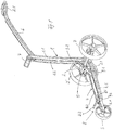
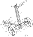
- the trained as a golf bag Caddy Dolly in Fig. 1 has in the operating position an upright first elongate frame part 1 with a cross member 2 at the lower end, on whose opposite ends rotatable rear wheels 3 and 3 'are pivotably articulated with its axis of rotation. From the lower end of the upright first frame part 1 extends horizontally a second elongated frame part 4, at the front end of a rotatable front wheel 5 is articulated pivotably with its axis of rotation.
- the upright first frame part 1 consists of two parallel tubular bodies 1.1 and 1.2, which are rigidly connected to the preferably designed as a rectangular tube cross member 2 by a welded joint.
- a handle bar 6 is pivotally mounted, which is provided at its free end with a handle 6.1.
- an arcuate male member 7 is fixed, the opposite end of which can be inserted into tabs of a golf bag, not shown, to hold the golf bag on the Caddy in an upright position.
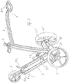
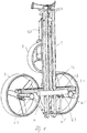
- Fig. 2 shows a projecting in the direction of travel forward approach 2.1 in the middle of the cross member 2, on the two frame struts 4.1 and 4.2 of the operating position of the Fig. 1 horizontal second frame part 4 are articulated.
- the second frame part 4 is approximately U-shaped with the two frame struts 4.1 and 4.2 as legs and a bracket 4.3 formed as a web.
- a Radhaltebügel 5.1 is articulated with a pivot axis in the longitudinal direction of the frame struts 4.1 and 4.2 so that the Radhaltebügel 5.1 can be pivoted after releasing a lock so that the plane of the front wheel 5 is in the plane of the frame struts 4.1 and 4.2, like this is the carrying position in Fig. 2 shows.
- an engagement member may be provided on one of the two components, which engages in a recess on the other component, wherein the respective engagement position is acted upon by a spring.
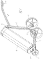
- a trained example by an angled rod support 8 is fixed, which in the operating position of Fig. 1 obliquely forward and projecting from the second frame part 4 upwards, so that a patch on the second frame part 4 golf bag T is supported in the longitudinal direction, like this Fig. 5 shows.
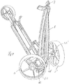
- a toggle lever 9 is respectively articulated between the frame struts 4.1, 4.2 and the tubular bodies 1.1, 1.2 near the cross member 2, which in the operating position of Fig. 1 in its extended position, the two frame parts 1 and 4 holds at an angle of about 90 ° to each other and can be folded by a hinge connection 9.3 in the central region between the toggle parts 9.1 and 9.2, as the intermediate position in Fig. 3 shows.
- an axle body 3.1 and 3.1 'of the associated rear wheel 3 or 3' is articulated at approximately half the first frame part 1 or in the longitudinal direction of the first frame part 1 perpendicular to the longitudinal extension of the cross member 2 at the ends of the cross member 2 , so that the axle body 3.1, 3.1 ', in the operating position of Fig. 1 is aligned in extension of the cross member 2, can be pivoted in a rotated by about 90 ° position, such as Fig. 2 shows in the supporting position, in which the axle body 3.1, 3.1 'are approximately perpendicular to the longitudinal extent of the cross member 2.
- the rear wheels 3 and 3 'are rotatably connected to the axle body 3.1 and 3.1' connected or rotatably mounted at one end of each axle body.
- the two axle bodies are each via a link 10 and 10 ' articulated to the lower end of the associated frame struts 4.1 and 4.2, respectively, so that when folding up in the operating position about horizontally lying second frame part 4 in Fig. 3 the two axle body 3.1 and 3.1 'on the links 10 and 10' relative to the cross member 2 in the support position in Fig. 2 be pivoted, in which the plane of the rear wheels 3 and 3 'is approximately parallel to the plane of the folded frame parts 1 and 4.
- the front wheel 5 is pivoted by pulling away from the second frame part 4 against the force of a spring of a locking not shown with the Radtragbügel 5.1 about its axis, so that the axis of rotation of the front wheel 5 is approximately perpendicular to the cross member 2 ,
- the wheel support bracket 5.1 of the front wheel 5 along its pivot axis extending in the longitudinal direction of the second frame part 4, relative to the second frame part 4 extendable and retractable formed, so that the driving position of the front wheel in the operating position of Fig. 1 can also be positioned at a greater distance from the front end of the horizontal second frame part 4.
- a rod between the two frame struts 4.1 and 4.2 extend in the direction of the pivot axis on the bracket 4.3, wherein the Radhaltebügel 5.1 along this rod is extendable and can be inserted again in the supporting position.
- articulated lever 9 between the first and second frame part 1 and 4 may also be hinged a compression spring through which the two frame parts 1 and 4 are pressed apart in the operating position and which is displaced when folding the two frame parts, for example along one of the frame parts with one end, so she does not push apart the two frame parts.
- various holding devices can be provided for the golf bag G to be supported on the frame parts 1 and 4.
- the bent Einsteckbügel 7 for insertion into tabs on the golf bag can also be replaced or supplemented by a band that can be placed around the golf bag and this holds on the first frame part 1.
- the frame parts 1 and 4 can be configured in a different manner, for example by a single frame strut instead of the illustrated two frame struts. Also, the frame parts 1 and / or 4 may be formed as elongated plates.
- the second frame member 4 individual support struts 8.1 and 8.2 can also be formed by another support 8, for example in the form of a bracket or a plate between the two frame struts 4.1 and 4.2.
- Fig. 6 shows a perspective view of a second embodiment of the trolley.
- the front wheel 5 is rotatably supported by an approximately L-shaped bracket 5.2, the short leg is transverse to the wheel plane in the position of Fig. 6 extends.
- This short leg is through in the wheel plane in Fig. 6 extending pivot axis connected to a guide body 5.3, located in Fig. 6 extends along the second frame part 4.
- This guide body 5.3 is by a transverse to the axis of rotation of the front wheel 5 pivot axis 5.4 in Fig. 6 connected to the second frame part 4.
- the bracket 5.2 the plane of the front wheel can be pivoted by about 90 °, while the guide body 5.3 can be pivoted about 180 ° relative to the second frame part 4, as this Fig. 7 shows.
- Fig. 7 shows a locking pin 5.5 on the bracket 5.2, which engages in a notch on the guide body 5.3 in the respective pivot position to fix the front wheel 5 in the respective pivot position relative to the guide body 5.3, which may also be provided with a detent relative to the second frame part 4.
- the cross member 2 is formed in the manner of a narrow plate in the second embodiment, but in contrast to the first embodiment, for example by welding, with the second frame part 4 is connected so that the plane of the cross member. 2 approximately perpendicular to the second frame part 4, such as Fig. 6 shows, so that when pivoting the second frame part 4 in Fig. 7 and the cross member 2 is pivoted with.
- the cross member 2 can with the second frame part 4 from the operating position in Fig. 6 , in which the plane of the cross member 2 is approximately parallel to the longitudinal extent of the first frame part 1, by about 90 ° in the carrying position in Fig. 8 be pivoted, in which the plane of the cross member 2 is approximately perpendicular to the first frame part 1.
- the cross member 2 itself is pivotally connected via a U-shaped bracket with the first frame part 1, wherein the two legs of this U-shaped bracket are hinged to the end portions of the two struts of the first frame part 1.
- the cross member 2 in the operating position of Fig. 6 in relation to the embodiment according to Fig. 8 positioned upright, so that the axle body 3.1 and 3.1 'are hinged to the back of the cross member 2.
- the wheels 3 In the folded position to Fig. 8 then are the wheels 3 on the same side as the folded down front wheel 5, resulting in a compact structure in the support position.
- the provided in the first embodiment support 9 between the first frame part 1 and second frame part 4 is in the second embodiment after Fig. 6 to 8 unavailable.
- the support in the operating position is taken over by the used between the holders 7 and 8 golf bag.
- the handle bar 6 is formed straight ahead in the second embodiment and can be folded in the folded position between the two struts of the first frame part 1, wherein the handle part 6.1 can be fixed by means of a detent on the frame part 1, as in Fig. 8 indicated at 12.
- the trolley described can also be provided with an electric drive motor, through which the rear wheels 3 are driven.
- electric motors with transmission are respectively integrated in the axle bodies 3.1 and 3.1 '.
- a corresponding control panel with battery insert can be provided in this case.
- the trolley described can not only be used for golf bags, it is also suitable for elongated containers that lean against the first frame part 1 and rest on the second frame part 4. In other words, the trolley described can be used in many ways.
Landscapes
- Engineering & Computer Science (AREA)
- Chemical & Material Sciences (AREA)
- Combustion & Propulsion (AREA)
- Transportation (AREA)
- Mechanical Engineering (AREA)
- Health & Medical Sciences (AREA)
- General Health & Medical Sciences (AREA)
- Physical Education & Sports Medicine (AREA)
- Handcart (AREA)
Claims (11)
- Chariot de transport à trois roues, en particulier pour un sac de golf (G), comprenant- une première partie de cadre allongée (1) à une zone d'extrémité de laquelle une deuxième partie de cadre allongée (4) est montée avec une zone d'extrémité pouvant pivoter par rapport à la première partie de cadre (1),- dans lequel au niveau d'une zone d'extrémité libre de la deuxième partie de cadre (4), une roue avant (5) est montée de façon à pouvoir pivoter sur un étrier de support de roue (5.1, 5.2) avec un axe de pivotement par le biais duquel le plan de la roue avant (5) peut pivoter d'environ 90°, et- dans lequel les deux roues arrière (3, 3') sont articulées au niveau des zones d'extrémité d'une traverse allongée (2) dans la zone d'articulation entre les première et deuxième parties de cadre (1, 4) de façon à pouvoir pivoter de telle sorte que leur axe de rotation peut pivoter d'une position à peu près en prolongement de la traverse (2) dans une position à peu près perpendiculaire par rapport à la traverse (2) et inversement,- dans lequel les roues arrière (3, 3') sont articulées par un corps d'axe (3.1, 3.1') de façon à pouvoir pivoter d'environ 90° sur la traverse (2), caractérisé en ce que- les roues arrière (3, 3') sont reliées par un guidon en forme de tige (10, 10') entre la première partie de cadre (1) et les corps d'axe (3.1, 3.1') de telle sorte que lors du pivotement des parties de cadre (1, 4) l'une par rapport à l'autre, les roues arrière (3, 3') pivotent d'environ 90° par rapport à la traverse (2).
- Chariot de transport à trois roues, en particulier pour un sac de golf (G), comprenant- une première partie de cadre allongée (1) à une zone d'extrémité de laquelle une deuxième partie de cadre allongée (4) est montée avec une zone d'extrémité pouvant pivoter par rapport à la première partie de cadre (1),- dans lequel au niveau d'une zone d'extrémité libre de la deuxième partie de cadre (4), une roue avant (5) est montée de façon à pouvoir pivoter sur un étrier de support de roue (5.1, 5.2) avec un axe de pivotement par le biais duquel le plan de la roue avant (5) peut pivoter d'environ 90°, et- dans lequel les deux roues arrière (3, 3') sont articulées au niveau des zones d'extrémité d'une traverse allongée (2) dans la zone d'articulation entre les première et deuxième parties de cadre (1, 4) de façon à pouvoir pivoter de telle sorte que leur axe de rotation peut pivoter d'une position à peu près en prolongement de la traverse (2) dans une position à peu près perpendiculaire par rapport à la traverse (2) et inversement,- dans lequel les roues arrière (3, 3') sont articulées par un corps d'axe (3.1, 3.1') de façon à pouvoir pivoter d'environ 90° sur la traverse (2), caractérisé en ce- que les roues arrière (3, 3') sont reliées par un guidon en forme de tige (10, 10') entre la deuxième partie de cadre (4) et les corps d'axe (3.1, 3.1') de telle sorte que lors du pivotement des parties de cadre (1, 4) l'une par rapport à l'autre, les roues arrière (3, 3') pivotent d'environ 90° par rapport à la traverse (2).
- Chariot de transport selon la revendication 2, dans lequel la traverse (2) est reliée au niveau de l'extrémité inférieure de la première partie de cadre (1) de façon rigide avec celle-ci.
- Chariot de transport selon la revendication 1, dans lequel la traverse (2) est reliée de façon rigide à la deuxième partie de cadre (4) et est articulée de façon à pouvoir pivoter au niveau de la première partie de cadre (1).
- Chariot de transport selon l'une quelconque des revendications 1 à 4, dans lequel l'étrier de support de roue (5.1, 5.2) peut être sorti et rentré par rapport à la deuxième partie de cadre (4) sur le plan longitudinal de son axe de pivotement.
- Chariot de transport selon l'une quelconque des revendications précédentes, dans lequel entre les première et deuxième parties de cadre (1, 4) est prévu un système d'appui (9) qui maintient l'une par rapport à l'autre les deux parties de cadre (1, 4) dans la position fonctionnelle dans un angle et permet un pivotement des deux parties de cadre (1, 4) l'une par rapport à l'autre.
- Chariot de transport selon l'une quelconque des revendications précédentes, dans lequel au niveau de l'extrémité libre de la première partie de cadre (1), un arc de préhension (6) est articulé de façon à pouvoir pivoter.
- Chariot de transport selon l'une quelconque des revendications précédentes, dans lequel au niveau de la première et de la deuxième partie de cadre (1, 4) est monté respectivement un système de retenue ou d'appui (7, 8) pour un sac de golf.
- Chariot de transport selon la revendication 8, dans lequel au niveau de la première partie de cadre (1), un arc enfichable courbé (7) est monté dans des attaches sur le sac de golf.
- Chariot de transport selon la revendication 8, dans lequel sur la deuxième partie de cadre (4), un support (8) dépassant des deux parties de cadre est monté pour soutenir un sac de golf.
- Chariot de transport selon l'une quelconque des revendications 1 à 10, dans lequel dans les corps d'axe (3.1, 3.1'), un moteur d'entraînement électrique pour les roues arrière (3, 3') est intégré.
Applications Claiming Priority (2)
| Application Number | Priority Date | Filing Date | Title |
|---|---|---|---|
| DE102013013339.4A DE102013013339A1 (de) | 2013-08-09 | 2013-08-09 | Zusammenlegbarer Transportwagen |
| PCT/EP2014/066998 WO2015018898A1 (fr) | 2013-08-09 | 2014-08-07 | Chariot de transport repliable |
Publications (3)
| Publication Number | Publication Date |
|---|---|
| EP3030471A1 EP3030471A1 (fr) | 2016-06-15 |
| EP3030471B1 true EP3030471B1 (fr) | 2018-10-17 |
| EP3030471B2 EP3030471B2 (fr) | 2022-07-20 |
Family
ID=51301277
Family Applications (1)
| Application Number | Title | Priority Date | Filing Date |
|---|---|---|---|
| EP14750200.9A Active EP3030471B2 (fr) | 2013-08-09 | 2014-08-07 | Chariot transporteur pliable |
Country Status (5)
| Country | Link |
|---|---|
| US (1) | US10213667B2 (fr) |
| EP (1) | EP3030471B2 (fr) |
| CN (1) | CN105793138B (fr) |
| DE (2) | DE102013013339A1 (fr) |
| WO (1) | WO2015018898A1 (fr) |
Families Citing this family (12)
| Publication number | Priority date | Publication date | Assignee | Title |
|---|---|---|---|---|
| CN204337672U (zh) * | 2014-12-26 | 2015-05-20 | 宁波稳泰运动器材有限公司 | 一种高尔夫手推车 |
| CN105151105B (zh) * | 2015-07-07 | 2017-10-17 | 福建欧仕儿童用品股份有限公司 | 童车轮子自动折叠结构 |
| AT518514B1 (de) | 2016-03-29 | 2021-06-15 | Unique Product & Design Co Ltd | Wagen, insbesondere Golfwagen |
| FR3052733A1 (fr) * | 2016-06-17 | 2017-12-22 | Trolem | Chariot support de bagage et / ou de sac de golf pliable selon au moins deux axes perpendiculaires entre eux |
| US9770636B1 (en) * | 2017-02-10 | 2017-09-26 | Sports World Enterprise Co., Ltd. | Rear wheel interlock folding mechanism of golf bag cart |
| EP3655308B1 (fr) * | 2017-07-21 | 2022-07-27 | Unique Product & Design Co., Ltd. | Chariot |
| CN107792138A (zh) * | 2017-11-10 | 2018-03-13 | 奥兹科技(成都)有限公司 | 可骑乘的折叠电动推车 |
| WO2019197421A2 (fr) * | 2018-04-13 | 2019-10-17 | Evotec-Swiss Ag | Chariot de golf |
| US11383777B2 (en) * | 2019-10-11 | 2022-07-12 | Honda Motor Co., Ltd. | Scooter auxiliary wheel system and method of use |
| GB2592273B (en) * | 2020-02-24 | 2023-11-15 | Stewart Golf Ltd | Foldable golf trolley |
| CN114750818B (zh) * | 2022-03-18 | 2023-08-04 | 好孩子儿童用品有限公司 | 儿童拖车 |
| WO2023183942A2 (fr) * | 2022-03-24 | 2023-09-28 | Zero Friction, LLC | Ensemble sac de golf motorisé |
Citations (9)
| Publication number | Priority date | Publication date | Assignee | Title |
|---|---|---|---|---|
| US4793622A (en) | 1988-03-07 | 1988-12-27 | Thomas Sydlow | Compact foldable golf cart |
| US5857684A (en) | 1993-06-01 | 1999-01-12 | Liao; Gordon | Collapsible golf cart |
| US6478315B1 (en) | 2000-11-27 | 2002-11-12 | Nick J. Manesis | Wheel assembly |
| US20040026897A1 (en) | 2002-08-12 | 2004-02-12 | David Wu | 3-fold type folding collapsible golf cart |
| DE102006057156A1 (de) | 2005-12-03 | 2007-06-06 | Roland Jungkind | Fahrzeug, insbesondere Caddie |
| DE202008001436U1 (de) | 2008-02-01 | 2008-04-03 | Unique Product & Design Co., Ltd., Yung Kang City | Klappbare Vorderradaufhängung für einen Golfkarren |
| DE202012101886U1 (de) | 2012-05-23 | 2012-07-02 | Unique Product & Design Co., Ltd. | Klappvorrichtung für dreifach klappbare dreirädrige Golftaschenwagen |
| DE202012102658U1 (de) | 2012-07-17 | 2012-08-14 | Unique Product & Design Co., Ltd. | Vorderradklappvorrichtung für dreirädrigen Wagen, umfassend einen Golftaschenwagen, Kinderwagen oder Warentransportwagen |
| GB2493805A (en) | 2012-05-11 | 2013-02-20 | Unique Product & Design Co Ltd | A golf cart with folding rear wheels |
Family Cites Families (15)
| Publication number | Priority date | Publication date | Assignee | Title |
|---|---|---|---|---|
| US6698789B2 (en) * | 2000-02-04 | 2004-03-02 | Sun Mountain Sports, Inc. | Collapsible golf cart |
| US7000939B2 (en) | 2000-06-28 | 2006-02-21 | Shapiro Richard N | Fold flat jogging strollers and cargo carriers including pivoting wheel axles and folding support frames |
| DE10052546A1 (de) | 2000-10-23 | 2002-04-25 | Wittenstein Gmbh & Co Kg | Vorrichtung zum Aufwickeln eines faden- oder drahtförmigen Gegenstandes |
| US6719319B2 (en) * | 2001-12-28 | 2004-04-13 | Unique Product & Design Co., Ltd. | collapsing device for the third wheel of a golf cart |
| US7934729B2 (en) * | 2004-06-04 | 2011-05-03 | Golf-N-Go, L.L.C. | Sports bag with integral transportation system |
| US7137644B2 (en) * | 2005-02-28 | 2006-11-21 | Kevin Kimberley | Collapsible golf cart |
| US7219920B2 (en) * | 2005-03-29 | 2007-05-22 | Wen-Tsan Lin | Easily detached and assembled golf cart with auxiliary wheel |
| DE202005018936U1 (de) * | 2005-12-03 | 2007-01-11 | Jungkind, Roland | Fahrzeug |
| CN201239495Y (zh) * | 2008-08-22 | 2009-05-20 | 黄景棠 | 折叠式高尔夫球手推车 |
| CN201389305Y (zh) * | 2009-04-10 | 2010-01-27 | 张盛 | 一步收合高尔夫球车 |
| US8403355B2 (en) * | 2010-11-10 | 2013-03-26 | Unique Product & Design Co., Ltd. | Golf bag cart foldable device |
| US8408562B1 (en) * | 2011-10-12 | 2013-04-02 | Adept Industries Limited | Golf bag cart |
| US8544871B1 (en) * | 2012-05-11 | 2013-10-01 | Unique Product & Design Co., Ltd. | Three-fold three-wheel golf bag cart folding device |
| US8500140B1 (en) * | 2012-06-29 | 2013-08-06 | Unique Product & Design Co., Ltd. | Front wheel folding device for three-wheel cart including golf bag cart, baby cart or goods transport cart |
| US9764752B2 (en) * | 2014-12-19 | 2017-09-19 | Unique Product & Design Co., Ltd. | Compact wheeled carrier device with movable, stowable rear wheels and frame |
-
2013
- 2013-08-09 DE DE102013013339.4A patent/DE102013013339A1/de not_active Withdrawn
-
2014
- 2014-08-07 EP EP14750200.9A patent/EP3030471B2/fr active Active
- 2014-08-07 DE DE202014011046.8U patent/DE202014011046U1/de not_active Expired - Lifetime
- 2014-08-07 US US14/911,255 patent/US10213667B2/en active Active
- 2014-08-07 WO PCT/EP2014/066998 patent/WO2015018898A1/fr not_active Ceased
- 2014-08-07 CN CN201480051898.3A patent/CN105793138B/zh active Active
Patent Citations (9)
| Publication number | Priority date | Publication date | Assignee | Title |
|---|---|---|---|---|
| US4793622A (en) | 1988-03-07 | 1988-12-27 | Thomas Sydlow | Compact foldable golf cart |
| US5857684A (en) | 1993-06-01 | 1999-01-12 | Liao; Gordon | Collapsible golf cart |
| US6478315B1 (en) | 2000-11-27 | 2002-11-12 | Nick J. Manesis | Wheel assembly |
| US20040026897A1 (en) | 2002-08-12 | 2004-02-12 | David Wu | 3-fold type folding collapsible golf cart |
| DE102006057156A1 (de) | 2005-12-03 | 2007-06-06 | Roland Jungkind | Fahrzeug, insbesondere Caddie |
| DE202008001436U1 (de) | 2008-02-01 | 2008-04-03 | Unique Product & Design Co., Ltd., Yung Kang City | Klappbare Vorderradaufhängung für einen Golfkarren |
| GB2493805A (en) | 2012-05-11 | 2013-02-20 | Unique Product & Design Co Ltd | A golf cart with folding rear wheels |
| DE202012101886U1 (de) | 2012-05-23 | 2012-07-02 | Unique Product & Design Co., Ltd. | Klappvorrichtung für dreifach klappbare dreirädrige Golftaschenwagen |
| DE202012102658U1 (de) | 2012-07-17 | 2012-08-14 | Unique Product & Design Co., Ltd. | Vorderradklappvorrichtung für dreirädrigen Wagen, umfassend einen Golftaschenwagen, Kinderwagen oder Warentransportwagen |
Also Published As
| Publication number | Publication date |
|---|---|
| EP3030471A1 (fr) | 2016-06-15 |
| WO2015018898A1 (fr) | 2015-02-12 |
| CN105793138A (zh) | 2016-07-20 |
| US10213667B2 (en) | 2019-02-26 |
| US20160184676A1 (en) | 2016-06-30 |
| CN105793138B (zh) | 2019-05-03 |
| EP3030471B2 (fr) | 2022-07-20 |
| DE202014011046U1 (de) | 2017-09-06 |
| DE102013013339A1 (de) | 2015-02-12 |
Similar Documents
| Publication | Publication Date | Title |
|---|---|---|
| EP3030471B1 (fr) | Chariot transporteur pliable | |
| DE3423528C2 (de) | Transportwagen | |
| EP3103712B1 (fr) | Scooter pliable | |
| DE202022102086U1 (de) | Faltbarer Bollerwagen mit faltbarer Tischplatte | |
| DE2723697C3 (de) | Klappbares Fahrgestell für einen abnehmbaren Kinderwagenaufsatz | |
| AT518514B1 (de) | Wagen, insbesondere Golfwagen | |
| EP1008491B1 (fr) | Porte-bagages arrière sur crochet d'attelage de véhicule | |
| DE3124916A1 (de) | Anhaenger fuer zweiradfahrzeuge | |
| WO2008109897A1 (fr) | Chariot | |
| DE202016003705U1 (de) | Zusammenklappbare Gepäckkarre | |
| DE102014222149B4 (de) | Klappfahrrad | |
| DE202010013007U1 (de) | Schiebewagengestell | |
| WO2016066385A1 (fr) | Vélo pliant | |
| DE202016104928U1 (de) | Klapproller | |
| EP3287339B1 (fr) | Calèche | |
| DE102012208048B3 (de) | Golfcaddy | |
| DE2644634C2 (fr) | ||
| DE2234359A1 (de) | Faltkinderwagen | |
| DE398233C (de) | Zweiraedriger Handwagen | |
| DE862713C (de) | Zusammenlegbarer Kinderwagen | |
| DE19953897A1 (de) | Vorrichtung zum Abschleppen eines Fahrrades | |
| EP1799525B1 (fr) | Chassis pour chariot deplaçable manuellement, en particulier chariot de golf | |
| DE202016102410U1 (de) | Zusammenklappbares Gestell mit Gasdruckfeder für einen Kinder- oder Einkaufswagen | |
| EP0625461B1 (fr) | Voiture d'enfant ou de poupée comprenant un bati pliable en forme de cisaille et un panier | |
| DE823984C (de) | Zusammenklappbarer Kinderwagen |
Legal Events
| Date | Code | Title | Description |
|---|---|---|---|
| PUAI | Public reference made under article 153(3) epc to a published international application that has entered the european phase |
Free format text: ORIGINAL CODE: 0009012 |
|
| 17P | Request for examination filed |
Effective date: 20160309 |
|
| AK | Designated contracting states |
Kind code of ref document: A1 Designated state(s): AL AT BE BG CH CY CZ DE DK EE ES FI FR GB GR HR HU IE IS IT LI LT LU LV MC MK MT NL NO PL PT RO RS SE SI SK SM TR |
|
| AX | Request for extension of the european patent |
Extension state: BA ME |
|
| DAX | Request for extension of the european patent (deleted) | ||
| STAA | Information on the status of an ep patent application or granted ep patent |
Free format text: STATUS: EXAMINATION IS IN PROGRESS |
|
| 17Q | First examination report despatched |
Effective date: 20170803 |
|
| RIC1 | Information provided on ipc code assigned before grant |
Ipc: B62B 3/02 20060101AFI20180531BHEP Ipc: B62B 5/00 20060101ALN20180531BHEP Ipc: B62B 3/10 20060101ALN20180531BHEP Ipc: B62B 3/12 20060101ALI20180531BHEP |
|
| GRAP | Despatch of communication of intention to grant a patent |
Free format text: ORIGINAL CODE: EPIDOSNIGR1 |
|
| STAA | Information on the status of an ep patent application or granted ep patent |
Free format text: STATUS: GRANT OF PATENT IS INTENDED |
|
| INTG | Intention to grant announced |
Effective date: 20180710 |
|
| GRAS | Grant fee paid |
Free format text: ORIGINAL CODE: EPIDOSNIGR3 |
|
| GRAA | (expected) grant |
Free format text: ORIGINAL CODE: 0009210 |
|
| STAA | Information on the status of an ep patent application or granted ep patent |
Free format text: STATUS: THE PATENT HAS BEEN GRANTED |
|
| AK | Designated contracting states |
Kind code of ref document: B1 Designated state(s): AL AT BE BG CH CY CZ DE DK EE ES FI FR GB GR HR HU IE IS IT LI LT LU LV MC MK MT NL NO PL PT RO RS SE SI SK SM TR |
|
| REG | Reference to a national code |
Ref country code: GB Ref legal event code: FG4D Free format text: NOT ENGLISH |
|
| REG | Reference to a national code |
Ref country code: CH Ref legal event code: EP |
|
| REG | Reference to a national code |
Ref country code: IE Ref legal event code: FG4D Free format text: LANGUAGE OF EP DOCUMENT: GERMAN |
|
| REG | Reference to a national code |
Ref country code: AT Ref legal event code: REF Ref document number: 1053639 Country of ref document: AT Kind code of ref document: T Effective date: 20181115 Ref country code: DE Ref legal event code: R096 Ref document number: 502014009815 Country of ref document: DE |
|
| REG | Reference to a national code |
Ref country code: CH Ref legal event code: NV Representative=s name: SCHMAUDER AND PARTNER AG PATENT- UND MARKENANW, CH |
|
| REG | Reference to a national code |
Ref country code: NL Ref legal event code: FP |
|
| REG | Reference to a national code |
Ref country code: LT Ref legal event code: MG4D |
|
| PG25 | Lapsed in a contracting state [announced via postgrant information from national office to epo] |
Ref country code: FI Free format text: LAPSE BECAUSE OF FAILURE TO SUBMIT A TRANSLATION OF THE DESCRIPTION OR TO PAY THE FEE WITHIN THE PRESCRIBED TIME-LIMIT Effective date: 20181017 Ref country code: LV Free format text: LAPSE BECAUSE OF FAILURE TO SUBMIT A TRANSLATION OF THE DESCRIPTION OR TO PAY THE FEE WITHIN THE PRESCRIBED TIME-LIMIT Effective date: 20181017 Ref country code: ES Free format text: LAPSE BECAUSE OF FAILURE TO SUBMIT A TRANSLATION OF THE DESCRIPTION OR TO PAY THE FEE WITHIN THE PRESCRIBED TIME-LIMIT Effective date: 20181017 Ref country code: LT Free format text: LAPSE BECAUSE OF FAILURE TO SUBMIT A TRANSLATION OF THE DESCRIPTION OR TO PAY THE FEE WITHIN THE PRESCRIBED TIME-LIMIT Effective date: 20181017 Ref country code: HR Free format text: LAPSE BECAUSE OF FAILURE TO SUBMIT A TRANSLATION OF THE DESCRIPTION OR TO PAY THE FEE WITHIN THE PRESCRIBED TIME-LIMIT Effective date: 20181017 Ref country code: PL Free format text: LAPSE BECAUSE OF FAILURE TO SUBMIT A TRANSLATION OF THE DESCRIPTION OR TO PAY THE FEE WITHIN THE PRESCRIBED TIME-LIMIT Effective date: 20181017 Ref country code: NO Free format text: LAPSE BECAUSE OF FAILURE TO SUBMIT A TRANSLATION OF THE DESCRIPTION OR TO PAY THE FEE WITHIN THE PRESCRIBED TIME-LIMIT Effective date: 20190117 Ref country code: IS Free format text: LAPSE BECAUSE OF FAILURE TO SUBMIT A TRANSLATION OF THE DESCRIPTION OR TO PAY THE FEE WITHIN THE PRESCRIBED TIME-LIMIT Effective date: 20190217 Ref country code: BG Free format text: LAPSE BECAUSE OF FAILURE TO SUBMIT A TRANSLATION OF THE DESCRIPTION OR TO PAY THE FEE WITHIN THE PRESCRIBED TIME-LIMIT Effective date: 20190117 |
|
| PG25 | Lapsed in a contracting state [announced via postgrant information from national office to epo] |
Ref country code: PT Free format text: LAPSE BECAUSE OF FAILURE TO SUBMIT A TRANSLATION OF THE DESCRIPTION OR TO PAY THE FEE WITHIN THE PRESCRIBED TIME-LIMIT Effective date: 20190217 Ref country code: GR Free format text: LAPSE BECAUSE OF FAILURE TO SUBMIT A TRANSLATION OF THE DESCRIPTION OR TO PAY THE FEE WITHIN THE PRESCRIBED TIME-LIMIT Effective date: 20190118 Ref country code: SE Free format text: LAPSE BECAUSE OF FAILURE TO SUBMIT A TRANSLATION OF THE DESCRIPTION OR TO PAY THE FEE WITHIN THE PRESCRIBED TIME-LIMIT Effective date: 20181017 Ref country code: RS Free format text: LAPSE BECAUSE OF FAILURE TO SUBMIT A TRANSLATION OF THE DESCRIPTION OR TO PAY THE FEE WITHIN THE PRESCRIBED TIME-LIMIT Effective date: 20181017 Ref country code: AL Free format text: LAPSE BECAUSE OF FAILURE TO SUBMIT A TRANSLATION OF THE DESCRIPTION OR TO PAY THE FEE WITHIN THE PRESCRIBED TIME-LIMIT Effective date: 20181017 |
|
| REG | Reference to a national code |
Ref country code: DE Ref legal event code: R026 Ref document number: 502014009815 Country of ref document: DE |
|
| PLBI | Opposition filed |
Free format text: ORIGINAL CODE: 0009260 |
|
| PLAX | Notice of opposition and request to file observation + time limit sent |
Free format text: ORIGINAL CODE: EPIDOSNOBS2 |
|
| PG25 | Lapsed in a contracting state [announced via postgrant information from national office to epo] |
Ref country code: CZ Free format text: LAPSE BECAUSE OF FAILURE TO SUBMIT A TRANSLATION OF THE DESCRIPTION OR TO PAY THE FEE WITHIN THE PRESCRIBED TIME-LIMIT Effective date: 20181017 Ref country code: DK Free format text: LAPSE BECAUSE OF FAILURE TO SUBMIT A TRANSLATION OF THE DESCRIPTION OR TO PAY THE FEE WITHIN THE PRESCRIBED TIME-LIMIT Effective date: 20181017 Ref country code: IT Free format text: LAPSE BECAUSE OF FAILURE TO SUBMIT A TRANSLATION OF THE DESCRIPTION OR TO PAY THE FEE WITHIN THE PRESCRIBED TIME-LIMIT Effective date: 20181017 |
|
| 26 | Opposition filed |
Opponent name: VAN GENDEREN, MARGARETHA MARIA Effective date: 20190715 |
|
| PLBB | Reply of patent proprietor to notice(s) of opposition received |
Free format text: ORIGINAL CODE: EPIDOSNOBS3 |
|
| PG25 | Lapsed in a contracting state [announced via postgrant information from national office to epo] |
Ref country code: SM Free format text: LAPSE BECAUSE OF FAILURE TO SUBMIT A TRANSLATION OF THE DESCRIPTION OR TO PAY THE FEE WITHIN THE PRESCRIBED TIME-LIMIT Effective date: 20181017 Ref country code: EE Free format text: LAPSE BECAUSE OF FAILURE TO SUBMIT A TRANSLATION OF THE DESCRIPTION OR TO PAY THE FEE WITHIN THE PRESCRIBED TIME-LIMIT Effective date: 20181017 Ref country code: RO Free format text: LAPSE BECAUSE OF FAILURE TO SUBMIT A TRANSLATION OF THE DESCRIPTION OR TO PAY THE FEE WITHIN THE PRESCRIBED TIME-LIMIT Effective date: 20181017 Ref country code: SK Free format text: LAPSE BECAUSE OF FAILURE TO SUBMIT A TRANSLATION OF THE DESCRIPTION OR TO PAY THE FEE WITHIN THE PRESCRIBED TIME-LIMIT Effective date: 20181017 |
|
| PG25 | Lapsed in a contracting state [announced via postgrant information from national office to epo] |
Ref country code: SI Free format text: LAPSE BECAUSE OF FAILURE TO SUBMIT A TRANSLATION OF THE DESCRIPTION OR TO PAY THE FEE WITHIN THE PRESCRIBED TIME-LIMIT Effective date: 20181017 |
|
| PG25 | Lapsed in a contracting state [announced via postgrant information from national office to epo] |
Ref country code: TR Free format text: LAPSE BECAUSE OF FAILURE TO SUBMIT A TRANSLATION OF THE DESCRIPTION OR TO PAY THE FEE WITHIN THE PRESCRIBED TIME-LIMIT Effective date: 20181017 |
|
| RAP2 | Party data changed (patent owner data changed or rights of a patent transferred) |
Owner name: SNOWPIXIE CO., LTD. |
|
| PG25 | Lapsed in a contracting state [announced via postgrant information from national office to epo] |
Ref country code: LU Free format text: LAPSE BECAUSE OF NON-PAYMENT OF DUE FEES Effective date: 20190807 Ref country code: MC Free format text: LAPSE BECAUSE OF FAILURE TO SUBMIT A TRANSLATION OF THE DESCRIPTION OR TO PAY THE FEE WITHIN THE PRESCRIBED TIME-LIMIT Effective date: 20181017 |
|
| REG | Reference to a national code |
Ref country code: BE Ref legal event code: MM Effective date: 20190831 |
|
| REG | Reference to a national code |
Ref country code: DE Ref legal event code: R082 Ref document number: 502014009815 Country of ref document: DE Representative=s name: KLINGSEISEN, RINGS & PARTNER PATENTANWAELTE, DE Ref country code: DE Ref legal event code: R081 Ref document number: 502014009815 Country of ref document: DE Owner name: SNOWPIXIE CO., LTD., HITACHINAKA CITY, JP Free format text: FORMER OWNER: MS TRADE GMBH, 85737 ISMANING, DE |
|
| PG25 | Lapsed in a contracting state [announced via postgrant information from national office to epo] |
Ref country code: IE Free format text: LAPSE BECAUSE OF NON-PAYMENT OF DUE FEES Effective date: 20190807 |
|
| PG25 | Lapsed in a contracting state [announced via postgrant information from national office to epo] |
Ref country code: BE Free format text: LAPSE BECAUSE OF NON-PAYMENT OF DUE FEES Effective date: 20190831 |
|
| REG | Reference to a national code |
Ref country code: AT Ref legal event code: PC Ref document number: 1053639 Country of ref document: AT Kind code of ref document: T Owner name: SNOWPIXIE CO., LTD., JP Effective date: 20201006 |
|
| APBM | Appeal reference recorded |
Free format text: ORIGINAL CODE: EPIDOSNREFNO |
|
| APBP | Date of receipt of notice of appeal recorded |
Free format text: ORIGINAL CODE: EPIDOSNNOA2O |
|
| PG25 | Lapsed in a contracting state [announced via postgrant information from national office to epo] |
Ref country code: CY Free format text: LAPSE BECAUSE OF FAILURE TO SUBMIT A TRANSLATION OF THE DESCRIPTION OR TO PAY THE FEE WITHIN THE PRESCRIBED TIME-LIMIT Effective date: 20181017 |
|
| APAH | Appeal reference modified |
Free format text: ORIGINAL CODE: EPIDOSCREFNO |
|
| APBQ | Date of receipt of statement of grounds of appeal recorded |
Free format text: ORIGINAL CODE: EPIDOSNNOA3O |
|
| PG25 | Lapsed in a contracting state [announced via postgrant information from national office to epo] |
Ref country code: HU Free format text: LAPSE BECAUSE OF FAILURE TO SUBMIT A TRANSLATION OF THE DESCRIPTION OR TO PAY THE FEE WITHIN THE PRESCRIBED TIME-LIMIT; INVALID AB INITIO Effective date: 20140807 Ref country code: MT Free format text: LAPSE BECAUSE OF FAILURE TO SUBMIT A TRANSLATION OF THE DESCRIPTION OR TO PAY THE FEE WITHIN THE PRESCRIBED TIME-LIMIT Effective date: 20181017 |
|
| APBU | Appeal procedure closed |
Free format text: ORIGINAL CODE: EPIDOSNNOA9O |
|
| PUAH | Patent maintained in amended form |
Free format text: ORIGINAL CODE: 0009272 |
|
| STAA | Information on the status of an ep patent application or granted ep patent |
Free format text: STATUS: PATENT MAINTAINED AS AMENDED |
|
| PG25 | Lapsed in a contracting state [announced via postgrant information from national office to epo] |
Ref country code: MK Free format text: LAPSE BECAUSE OF FAILURE TO SUBMIT A TRANSLATION OF THE DESCRIPTION OR TO PAY THE FEE WITHIN THE PRESCRIBED TIME-LIMIT Effective date: 20181017 |
|
| 27A | Patent maintained in amended form |
Effective date: 20220720 |
|
| AK | Designated contracting states |
Kind code of ref document: B2 Designated state(s): AL AT BE BG CH CY CZ DE DK EE ES FI FR GB GR HR HU IE IS IT LI LT LU LV MC MK MT NL NO PL PT RO RS SE SI SK SM TR |
|
| REG | Reference to a national code |
Ref country code: DE Ref legal event code: R102 Ref document number: 502014009815 Country of ref document: DE |
|
| REG | Reference to a national code |
Ref country code: NL Ref legal event code: FP |
|
| REG | Reference to a national code |
Ref country code: NL Ref legal event code: PD Owner name: SNOWPIXIE CO., LTD.; JP Free format text: DETAILS ASSIGNMENT: CHANGE OF OWNER(S), ASSIGNMENT; FORMER OWNER NAME: MS-TRADE GMBH Effective date: 20240108 |
|
| REG | Reference to a national code |
Ref country code: GB Ref legal event code: 732E Free format text: REGISTERED BETWEEN 20240104 AND 20240110 |
|
| PGFP | Annual fee paid to national office [announced via postgrant information from national office to epo] |
Ref country code: NL Payment date: 20250826 Year of fee payment: 12 |
|
| PGFP | Annual fee paid to national office [announced via postgrant information from national office to epo] |
Ref country code: DE Payment date: 20250811 Year of fee payment: 12 |
|
| PGFP | Annual fee paid to national office [announced via postgrant information from national office to epo] |
Ref country code: GB Payment date: 20250827 Year of fee payment: 12 |
|
| PGFP | Annual fee paid to national office [announced via postgrant information from national office to epo] |
Ref country code: AT Payment date: 20250822 Year of fee payment: 12 Ref country code: FR Payment date: 20250826 Year of fee payment: 12 |
|
| PGFP | Annual fee paid to national office [announced via postgrant information from national office to epo] |
Ref country code: CH Payment date: 20250901 Year of fee payment: 12 |