EP3030532B2 - Procédé de combustion et de refroidissement de roches carbonatées dans un chaufour à régénération par courant continu - Google Patents
Procédé de combustion et de refroidissement de roches carbonatées dans un chaufour à régénération par courant continu Download PDFInfo
- Publication number
- EP3030532B2 EP3030532B2 EP14747837.4A EP14747837A EP3030532B2 EP 3030532 B2 EP3030532 B2 EP 3030532B2 EP 14747837 A EP14747837 A EP 14747837A EP 3030532 B2 EP3030532 B2 EP 3030532B2
- Authority
- EP
- European Patent Office
- Prior art keywords
- shaft
- cooling air
- carbonate rock
- fed
- cooling
- Prior art date
- Legal status (The legal status is an assumption and is not a legal conclusion. Google has not performed a legal analysis and makes no representation as to the accuracy of the status listed.)
- Active
Links
Images

Classifications
-
- C—CHEMISTRY; METALLURGY
- C04—CEMENTS; CONCRETE; ARTIFICIAL STONE; CERAMICS; REFRACTORIES
- C04B—LIME, MAGNESIA; SLAG; CEMENTS; COMPOSITIONS THEREOF, e.g. MORTARS, CONCRETE OR LIKE BUILDING MATERIALS; ARTIFICIAL STONE; CERAMICS; REFRACTORIES; TREATMENT OF NATURAL STONE
- C04B2/00—Lime, magnesia or dolomite
- C04B2/10—Preheating, burning calcining or cooling
- C04B2/12—Preheating, burning calcining or cooling in shaft or vertical furnaces
-
- C—CHEMISTRY; METALLURGY
- C04—CEMENTS; CONCRETE; ARTIFICIAL STONE; CERAMICS; REFRACTORIES
- C04B—LIME, MAGNESIA; SLAG; CEMENTS; COMPOSITIONS THEREOF, e.g. MORTARS, CONCRETE OR LIKE BUILDING MATERIALS; ARTIFICIAL STONE; CERAMICS; REFRACTORIES; TREATMENT OF NATURAL STONE
- C04B28/00—Compositions of mortars, concrete or artificial stone, containing inorganic binders or the reaction product of an inorganic and an organic binder, e.g. polycarboxylate cements
- C04B28/02—Compositions of mortars, concrete or artificial stone, containing inorganic binders or the reaction product of an inorganic and an organic binder, e.g. polycarboxylate cements containing hydraulic cements other than calcium sulfates
- C04B28/10—Lime cements or magnesium oxide cements
-
- F—MECHANICAL ENGINEERING; LIGHTING; HEATING; WEAPONS; BLASTING
- F27—FURNACES; KILNS; OVENS; RETORTS
- F27B—FURNACES, KILNS, OVENS OR RETORTS IN GENERAL; OPEN SINTERING OR LIKE APPARATUS
- F27B1/00—Shaft or like vertical or substantially vertical furnaces
- F27B1/005—Shaft or like vertical or substantially vertical furnaces wherein no smelting of the charge occurs, e.g. calcining or sintering furnaces
-
- F—MECHANICAL ENGINEERING; LIGHTING; HEATING; WEAPONS; BLASTING
- F27—FURNACES; KILNS; OVENS; RETORTS
- F27B—FURNACES, KILNS, OVENS OR RETORTS IN GENERAL; OPEN SINTERING OR LIKE APPARATUS
- F27B1/00—Shaft or like vertical or substantially vertical furnaces
- F27B1/02—Shaft or like vertical or substantially vertical furnaces with two or more shafts or chambers, e.g. multi-storey
- F27B1/04—Combinations or arrangements of shafts
-
- F—MECHANICAL ENGINEERING; LIGHTING; HEATING; WEAPONS; BLASTING
- F27—FURNACES; KILNS; OVENS; RETORTS
- F27B—FURNACES, KILNS, OVENS OR RETORTS IN GENERAL; OPEN SINTERING OR LIKE APPARATUS
- F27B1/00—Shaft or like vertical or substantially vertical furnaces
- F27B1/10—Details, accessories or equipment specially adapted for furnaces of these types
-
- F—MECHANICAL ENGINEERING; LIGHTING; HEATING; WEAPONS; BLASTING
- F27—FURNACES; KILNS; OVENS; RETORTS
- F27B—FURNACES, KILNS, OVENS OR RETORTS IN GENERAL; OPEN SINTERING OR LIKE APPARATUS
- F27B7/00—Rotary-drum furnaces, i.e. horizontal or slightly inclined
- F27B7/20—Details, accessories or equipment specially adapted for rotary-drum furnaces
- F27B7/38—Arrangements of cooling devices
-
- Y—GENERAL TAGGING OF NEW TECHNOLOGICAL DEVELOPMENTS; GENERAL TAGGING OF CROSS-SECTIONAL TECHNOLOGIES SPANNING OVER SEVERAL SECTIONS OF THE IPC; TECHNICAL SUBJECTS COVERED BY FORMER USPC CROSS-REFERENCE ART COLLECTIONS [XRACs] AND DIGESTS
- Y02—TECHNOLOGIES OR APPLICATIONS FOR MITIGATION OR ADAPTATION AGAINST CLIMATE CHANGE
- Y02P—CLIMATE CHANGE MITIGATION TECHNOLOGIES IN THE PRODUCTION OR PROCESSING OF GOODS
- Y02P40/00—Technologies relating to the processing of minerals
- Y02P40/40—Production or processing of lime, e.g. limestone regeneration of lime in pulp and sugar mills
Definitions
- the invention relates to a method for burning and cooling carbonate rocks in a direct current regenerative lime shaft furnace with two shafts which are operated alternately as a combustion shaft and as a regenerative shaft.
- the well-known furnace works cyclically, with burning only in the firing shaft, while the other shaft works as a regenerative shaft.
- the carbonate rock to be burned is continuously discharged via discharge devices at both shafts.
- the column of material sinks evenly in the shafts.
- the furnace is then reversed so that the shaft, which previously worked as a combustion shaft, becomes a regenerative shaft and the shaft, which previously worked as a regenerative shaft, in turn becomes a combustion shaft.
- the furnace is charged with carbonate rock during the reversing process or during the burning process at the regenerative shaft.
- In the lower area of the two shafts there are cooling zones for cooling the carbonate rock calcined in the upper area, the cooling air used for this being supplied partly in the area of the discharge devices and partly via a central displacement body arranged in each cooling zone.
- the quality of the end product depends crucially on the fact that the calcined carbonate rock sinks down as evenly as possible over the width of the shafts and that the cooling zone is designed in such a way that the most uniform possible cooling is guaranteed.
- Hannes Piringer "Bulk material movement, flow behavior and temperature distribution in the cooling zone of an 800 and 1000 tpd Maerz regenerative lime shaft kiln, Veitsch-Radex Rundschau 1/1999, pages 1 to 15 the above-described direct current regenerative lime shaft kiln is known.
- investigations for an optimal design of the cooling zone and the discharge organs are presented in more detail.
- the invention was based on the object of achieving even more uniform cooling in the cooling zones of a cocurrent regenerative lime shaft furnace with as little cooling air as possible.
- the new cooling air duct also reduces the total amount of cooling required for product cooling.
- calcining carbonate rock with a CaCO 3 content of more than 97% it is less than 0.7 Nm 3 / kg calcined carbonate rock, preferably less than 0.65 Nm 3 / kg calcined carbonate rock.
- a quantity of cooling air of more than 0.75 Nm 3 / kg of calcined carbonate rock has usually been required, especially in small stone ovens (fine stone ovens).
- 20-50% of the cooling air supplied to the two ducts is supplied to the combustion duct and the remaining amount is supplied to the regenerative duct.
- 30% +/- 10% of the cooling air supplied to the two ducts can be supplied to the combustion duct and the remaining amount can be supplied to the regenerative duct.
- the cooling air supplied in the area of the discharge devices is expediently supplied via material slopes formed in this area by the calcined and cooled carbonate rock. According to a further embodiment of the invention, the cooling air supplied in the area of the discharge devices should flow essentially upwards and towards the center of the shaft. The cooling air supplied via the displacement body, on the other hand, should flow essentially upwards and to the outer boundary of the shaft.
- the even cooling of the carbonate rock is also supported by the operation of the discharge device, which preferably discharges the calcined and cooled carbonate rock radially outwards and radially inwards, with 60-80% of the calcined and cooled carbonate rock being discharged outside and the rest inside.
- the cooling zone is preferably cylindrical or slightly conical and has an angle of inclination of more than 82 °. To ensure good cooling, the diameter at the lower end of the cooling zone should also be 1.1-1.5 times larger than the diameter at the lower end of the preheating and burning zone.
- the regulation of the amount of cooling air via the first to fourth cooling air lines takes place preferably via a flap system that can be controlled by the control device.
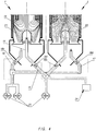
- the in Fig. 1 The shown direct current regenerative lime shaft furnace for burning and cooling carbonate rocks has two shafts 1, 2, which are operated in a manner known per se alternately as a burning shaft and as a regenerative shaft.
- the carbonate rock 3 is added, for example, in a grain size range of 10 mm to 50 mm in an upper area of each shaft designed as a preheating and burning zone 4.
- fuel 5 is supplied via a fuel supply line 6 and combustion air 7 via at least one combustion air supply line 8.
- the carbonate rock 3 is preheated and calcined in the area of the preheating and combustion zone.
- the calcined carbonate rock then passes into a lower region of each shaft, designed as a cooling zone 9 and having a central displacement body 10, 11, and is cooled there.
- the cooled, calcined carbonate rock is then discharged via a discharge device 12, 13 assigned to each shaft.
- the carbonate rock 3 thus migrates from top to bottom following the force of gravity.
- the usual length of stay is, for example, 20 hours.
- the amount of the cooled carbonate rock discharged from the bottom is supplemented in the upper area by carbonate rock 3 still to be treated.
- the calcined carbonate rock is cooled by cooling air which is fed to the cooling zone 9 at two points, namely via the displacement body 10 or 11 and in the area of the discharge devices 12 or 13.
- the displacement bodies are each formed centrally in the cooling zone and can, for example, be conical or, as shown, rounded at the top. In the lower region of the displacement bodies 10, 11, these are provided with gas outlet openings 10a and 11a over their entire circumference.
- a first cooling air line 14 is connected to the gas openings 10a of the displacement body 10 of the shaft 1 and a second cooling air line 15 is connected to the gas outlet openings 11a of the combustion body 11 of the second shaft 2 for supplying cooling air via the displacement body.
- a third cooling air line 16 opens in the area of the discharge device 12 of the first shaft 1 and a fourth cooling air line 17 in the area of the discharge device 13 of the second shaft 2.
- a suitable flap system 18 which comprises at least a first flap 18a and a second flap 18b, the Air distribution to the amount of cooling air can be regulated via the four cooling air lines.
- Fig. 1 shows the flow conditions in a situation in which the shaft 1 is operated as a combustion shaft and the shaft 2 as a regeneration shaft.
- the flap system 18 is controlled via a controller not shown here in such a way that essentially the entire, but at least 90% of the amount of cooling air to be supplied to the shaft 1 is supplied to the displacement body 10 via the first cooling air line 14, while the amount of cooling air in the shaft 2 is essentially is supplied exclusively via the associated discharge device 13.
- the cooling air can thus optionally be supplied via the displacement body 10 or the displacement body 11 via the flap 18a. Suitable measures can be used to ensure that a smaller amount of sealing air still flows through the blocked cooling air line in order to avoid clogging of the gas outlet openings of the displacement bodies.
- the cooling air can be guided via the flap 18b either via the third cooling air line 16 or the fourth cooling air line 17, whereby the setting of a small amount of sealing air is also conceivable here.
- the third and fourth cooling air lines 16, 17 open below the discharge devices 12, 13, so that the cooling air passes over the material slopes 3a, 3b formed by the calcined and cooled carbonate rock onto the discharge devices 12, 13 (see FIG Fig. 2 ) is supplied.
- the combustion of the fuel 5 with the combustion air 7 forms flue gases 19 which exit the combustion zone downwards and enter the shaft 2 via the overflow channel 20 connecting the two shafts.
- Cooling air 21 is displaced by the flue gases flowing downwards from the combustion zone, so that the cooling air 21 essentially flows upwards and to the outer boundary of the shaft 1 in order to get there together with the flue gases via the overflow channel 20 into the shaft 2.
- the flow conditions in the regeneration shaft 2 are fundamentally different. On the one hand, there is no supply of combustion air from above and no combustion takes place either. Rather, the flue gases 19 and the cooling air 21 flow upwards from the shaft 1 together with the cooling air 22 from the shaft 2 and are discharged there via an exhaust pipe 23. Since the cooling air 22 in the shaft 2 is supplied essentially exclusively via the discharge device 13, a cooling air flow results which is oriented essentially upwards and towards the center of the shaft. After a specified cycle of 10-12 minutes, for example, the function of the two shafts changes, so that shaft 1 then becomes a regeneration shaft and shaft 2 functions as a combustion shaft.
- the supply of cooling air is then changed accordingly, so that it is always guaranteed that 90-100% of the amount of air to be supplied to the shaft that is currently functioning as a combustion shaft is supplied via the displacement body and a maximum of 10% in the area of the discharge device, while the 90-100% of the cooling air to be supplied to the regeneration shaft is supplied in the area of the discharge device and only a maximum of 10% via the displacement body.
- Fig. 4 are for the in Fig. 1 described situation, in which the shaft 1 is operated as a combustion shaft and the shaft 2 as a regeneration shaft, the flow lines of the cooling air 21 and 22 and the flue gases 19 are shown. It can be seen that the cooling zones are exposed to cooling air very evenly.
- cooling air lines 14 to 17 are each provided with a flap 18c, 18d, 18e and 18f that can be controlled via a control device 24.
- cooling air suppliers 25 are indicated schematically.
- isothermal lines 27 are established in the area of the cooling zone, which are essentially horizontal, so that very even cooling of the calcined carbonate rock is ensured over the width of the cooling zone. This means that there are no trough-shaped, sagging isothermal lines that could damage the discharge devices due to material that is too hot.
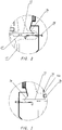
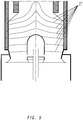
- the discharge devices 12, 13 are according to FIGS Figs. 2 and 3 designed so that the calcined and cooled carbonate rock can be discharged radially outwards or radially inwards.
- the discharge devices each have, for example, a segment-like discharge table which can be moved in the direction of the double arrow 27 via a sliding mechanism 26. If the discharge device 13 in the Fig. 2 The illustrated embodiment is moved to the left, it is pushed away below the carbonate rock until the rock falls down on the outside. When the discharge direction is moved in the opposite direction, the discharge takes place inwards.
- the discharge of the material also has a decisive influence on whether the carbonate rock slides down as evenly as possible over the entire width. With this type of discharge device, it has proven to be useful if 60-80% of the calcined and cooled carbonate rock is discharged to the outside and the rest to the inside.
- the diameter at the lower end of the cooling zone is chosen so that it is 1.1 to 1.5 times larger than the diameter at the lower end of the preheating and burning zone, the diameter being the inner diameter of the cooling zone or preheating and Burning zone is to be understood.
- the above-described air routing in the combustion shaft or regeneration shaft enables extremely efficient cooling, so that the entire amount of cooling air to be supplied when calcining carbonate rock with a CaCO 3 content of more than 97% to less than 0.7 Nm 3 / kg calcined carbonate rock, preferably can be reduced to less than 0.65 Nm 3 / kg calcined carbonate rock.
- This has the advantage that the amount of gas to be discharged via the exhaust line 23 is correspondingly reduced and the heat consumption of the furnace is reduced.
- the air guidance according to the invention also leads to a strong reduction in the previously determined marginal mobility of the flow.
- the risk of local areas in which recarbonization can occur is reduced.
Landscapes
- Engineering & Computer Science (AREA)
- Chemical & Material Sciences (AREA)
- Mechanical Engineering (AREA)
- General Engineering & Computer Science (AREA)
- Ceramic Engineering (AREA)
- Materials Engineering (AREA)
- Structural Engineering (AREA)
- Organic Chemistry (AREA)
- Physics & Mathematics (AREA)
- Thermal Sciences (AREA)
- Chemical Kinetics & Catalysis (AREA)
- Inorganic Chemistry (AREA)
- Vertical, Hearth, Or Arc Furnaces (AREA)
- Furnace Details (AREA)
- Tunnel Furnaces (AREA)
- Muffle Furnaces And Rotary Kilns (AREA)
Claims (8)
- Procédé de combustion et de refroidissement de roches carbonatées (3) dans un chaufour à régénération par courant continu avec deux cuves (1, 2), qui fonctionnent en alternance comme cuve de combustion et comme cuve de régénération, dans lequela. on charge la roche carbonatée (3) dans une région supérieure de chaque cuve, formant une zone de préchauffage et de combustion (4), et elle y est préchauffée et calcinée,b. on refroidit ensuite la roche carbonatée calcinée (3) dans une région inférieure de chaque cuve, formant une zone de refroidissement (9) et présentant un corps de déplacement central (10, 11),c. on extrait ensuite la roche carbonatée calcinée refroidie au moyen d'un dispositif d'extraction (12, 13) associé à chaque cuve (1, 2), et dans lequeld. on envoie dans la zone de refroidissement (9) pour le refroidissement de la roche carbonatée calcinée, de l'air de refroidissement (21, 22) que l'on introduit en partie dans la région du dispositif d'extraction (12, 13) et en partie via le corps de déplacement (10, 11),caractérisé en ce que la quantité d'air de refroidissement à fournir à la cuve de combustion est envoyée à raison de 90 à 100 % via le corps de déplacement et d'au maximum 10 % dans la région du dispositif d'extraction, tandis que la quantité d'air de refroidissement à fournir à la cuve de régénération est envoyée à raison de 90 à 100 % dans la région du dispositif d'extraction et d'au maximum 10 % via le corps de déplacement.
- Procédé selon la revendication 1, caractérisé en ce que l'on envoie de 20 % à 50 % de l'air de refroidissement fourni aux deux cuves (1, 2) à la cuve de combustion et la quantité restante à la cuve de régénération.
- Procédé selon la revendication 2, caractérisé en ce que l'on envoie 30 % ± 10 % de l'air de refroidissement fourni aux deux cuves (1, 2) à la cuve de combustion et la quantité restante à la cuve de régénération.
- Procédé selon la revendication 1, caractérisé en ce que l'on envoie l'air de refroidissement fourni dans la région des dispositifs d'extraction (12, 13) via des talus de matière (3a, 3b) se formant dans cette région par la roche carbonatée calcinée et refroidie.
- Procédé selon la revendication 1, caractérisé en ce que l'air de refroidissement fourni dans la région des dispositifs d'extraction (12, 13) s'écoule vers le haut et vers le milieu de la cuve.
- Procédé selon la revendication 1, caractérisé en ce que l'air de refroidissement fourni via les corps de déplacement (10, 11) s'écoule vers le haut et vers la paroi extérieure de la cuve.
- Procédé selon la revendication 1, caractérisé en ce que le dispositif d'extraction (12, 13) extrait radialement vers l'extérieur et radialement vers l'intérieur la roche carbonatée calcinée et refroidie, dans lequel 60 à 80 % de la roche carbonatée calcinée et refroidie sont extraits extérieurement et le reste intérieurement.
- Procédé selon la revendication 1, caractérisé en ce que lors de la calcination de roche carbonatée (3) présentant une teneur en CaCO3 de plus de 97 %, on envoie de l'air de refroidissement avec une quantité totale de moins de 0,70 Nm3/kg de roche carbonatée calcinée.
Priority Applications (1)
| Application Number | Priority Date | Filing Date | Title |
|---|---|---|---|
| PL14747837.4T PL3030532T5 (pl) | 2013-08-05 | 2014-07-28 | Sposób wypalania i chłodzenia skały węglanowej w regeneracyjnym piecu szybowym ze stałym przepływem i regeneracyjny piec wapienny ze stałym przepływem |
Applications Claiming Priority (2)
| Application Number | Priority Date | Filing Date | Title |
|---|---|---|---|
| DE102013108410.9A DE102013108410B3 (de) | 2013-08-05 | 2013-08-05 | Verfahren zum Brennen und Kühlen von Karbonatgesteinen in einem Gleichstrom-Regenerativ-Kalkschachtofen sowie ein Gleichstrom-Regenerativ-Kalkschachtofen |
| PCT/EP2014/002056 WO2015018504A1 (fr) | 2013-08-05 | 2014-07-28 | Procédé de combustion et de refroidissement de roches carbonatées dans un chaufour à régénération par courant continu et chaufour à régénération par courant continu |
Publications (3)
| Publication Number | Publication Date |
|---|---|
| EP3030532A1 EP3030532A1 (fr) | 2016-06-15 |
| EP3030532B1 EP3030532B1 (fr) | 2018-02-21 |
| EP3030532B2 true EP3030532B2 (fr) | 2021-05-19 |
Family
ID=51292902
Family Applications (1)
| Application Number | Title | Priority Date | Filing Date |
|---|---|---|---|
| EP14747837.4A Active EP3030532B2 (fr) | 2013-08-05 | 2014-07-28 | Procédé de combustion et de refroidissement de roches carbonatées dans un chaufour à régénération par courant continu |
Country Status (13)
| Country | Link |
|---|---|
| US (1) | US10301219B2 (fr) |
| EP (1) | EP3030532B2 (fr) |
| JP (1) | JP6371392B2 (fr) |
| CN (1) | CN105452186B (fr) |
| BR (1) | BR112016002340B1 (fr) |
| DE (1) | DE102013108410B3 (fr) |
| MX (1) | MX386839B (fr) |
| MY (1) | MY172379A (fr) |
| NO (1) | NO2911238T3 (fr) |
| PL (1) | PL3030532T5 (fr) |
| RU (1) | RU2652594C2 (fr) |
| TR (1) | TR201806988T4 (fr) |
| WO (1) | WO2015018504A1 (fr) |
Families Citing this family (12)
| Publication number | Priority date | Publication date | Assignee | Title |
|---|---|---|---|---|
| DE102016104076A1 (de) * | 2016-03-07 | 2017-09-07 | Maerz Ofenbau Ag | Anlage mit einem Ofen und Verfahren zum Betreiben einer solchen Anlage |
| DE102016112969A1 (de) | 2016-07-14 | 2018-01-18 | Thyssenkrupp Ag | Austragsvorrichtung für einen Schachtofen und Verfahren zum Austragen von Brenngut aus einem Schachtofen |
| FR3066810B1 (fr) | 2017-05-23 | 2019-06-14 | Arc France | Four combine |
| RU2724835C1 (ru) * | 2019-03-28 | 2020-06-25 | Общество С Ограниченной Ответственностью "Известа" | Способ обжига карбонатного материала в прямоточно-противоточной печи с двумя шахтами |
| RU2723793C1 (ru) * | 2019-10-21 | 2020-06-17 | Закрытое акционерное общество "Липецкметаллургпроект" | Способ обжига мелкодисперсных карбонатных материалов |
| TWI817086B (zh) * | 2020-02-26 | 2023-10-01 | 瑞士商邁爾茲歐芬堡公司 | 在ggr豎爐中燃燒含碳材料的方法 |
| CN111322879B (zh) * | 2020-04-07 | 2021-10-15 | 柳州钢铁股份有限公司 | 麦尔兹窑快速点火烘炉的方法 |
| CN111908811B (zh) * | 2020-08-07 | 2022-03-25 | 沈阳红杉科技有限公司 | 一种燃低热值燃料的双膛窑 |
| CA3218534A1 (fr) * | 2021-05-11 | 2022-11-17 | Tecforlime | Procede de decarbonatation de materiaux carbonates dans un four vertical a plusieurs cuves |
| CN113932601A (zh) * | 2021-09-01 | 2022-01-14 | 广西柳钢新材料科技有限公司 | 双膛窑冷却风控制分配方法 |
| CN113955956A (zh) * | 2021-11-30 | 2022-01-21 | 中冶京诚工程技术有限公司 | 双膛蓄热式石灰窑 |
| EP4506644A1 (fr) * | 2023-08-08 | 2025-02-12 | S.A. Lhoist Recherche Et Developpement | Four droit vertical à flux parallèles régénératifs |
Family Cites Families (12)
| Publication number | Priority date | Publication date | Assignee | Title |
|---|---|---|---|---|
| US3074706A (en) * | 1958-08-09 | 1963-01-22 | Schmid Alois | Method for carrying out endothermic processes in a shaft furnace |
| CH637760A5 (en) * | 1978-09-15 | 1983-08-15 | Maerz Ofenbau | Method for burning mineral, carbonate-containing raw materials in the co-current regenerative shaft furnace |
| CH638604A5 (de) * | 1978-12-29 | 1983-09-30 | Maerz Ofenbau | Verfahren zum brennen von mineralischen karbonathaltigen rohstoffen im gleichstrom-regenerativ-schachthofen. |
| CH647313A5 (de) * | 1980-04-30 | 1985-01-15 | Maerz Ofenbau | Regenerativ-schachtofen zum brennen von karbonathaltigen rohstoffen. |
| JPS57175754A (en) * | 1981-04-16 | 1982-10-28 | Nippon Kokan Kk | Operation of parallel flow regenaration type lime baking furnace |
| AT377248B (de) | 1982-07-12 | 1985-02-25 | Maerz Ofenbau | Verfahren und schachtofen zum brennen von kalkstein |
| US4747773A (en) * | 1986-03-21 | 1988-05-31 | Predescu Lucian A | Shaft kiln utilized for lime production |
| CH686459A5 (de) * | 1992-03-07 | 1996-03-29 | Maerz Ofenbau | Schachtofen zum Brennen von stuckigem, mineralischem Fuellgut. |
| RU2063594C1 (ru) * | 1992-07-24 | 1996-07-10 | Акционерное общество открытого типа Институт по проектированию и конструированию тепловых агрегатов "Стальпроект" | Способ обжига карбонатного сырья и регенеративная шахтная печь для обжига карбонатного сырья |
| RU2085816C1 (ru) * | 1993-07-06 | 1997-07-27 | Акционерное общество открытого типа "Западно-Сибирский металлургический комбинат" | Способ обжига кусковых карбонатных пород в двухшахтной прямоточно-противоточной печи |
| DK1038851T3 (da) * | 1999-02-27 | 2001-08-27 | Zeisel Peter Dipl Ing | Fremgangsmåde til brænding af stykkeformet brændingsråstof, navnlig af kalksten, dolomit og magnesit, og regenerativskaktovn til gennemførelse af fremgangsmåden |
| RU2166159C2 (ru) * | 1999-05-19 | 2001-04-27 | Открытое акционерное общество "Магнитогорский институт по проектированию металлургических заводов" | Противоточно-прямоточная шахтная печь для обжига карбонатных пород |
-
2013
- 2013-08-05 DE DE102013108410.9A patent/DE102013108410B3/de not_active Expired - Fee Related
-
2014
- 2014-07-28 CN CN201480044775.7A patent/CN105452186B/zh active Active
- 2014-07-28 TR TR2018/06988T patent/TR201806988T4/tr unknown
- 2014-07-28 RU RU2016104622A patent/RU2652594C2/ru active
- 2014-07-28 EP EP14747837.4A patent/EP3030532B2/fr active Active
- 2014-07-28 MX MX2016001523A patent/MX386839B/es unknown
- 2014-07-28 US US14/909,687 patent/US10301219B2/en active Active
- 2014-07-28 MY MYPI2016000158A patent/MY172379A/en unknown
- 2014-07-28 BR BR112016002340-4A patent/BR112016002340B1/pt active IP Right Grant
- 2014-07-28 WO PCT/EP2014/002056 patent/WO2015018504A1/fr not_active Ceased
- 2014-07-28 JP JP2016532259A patent/JP6371392B2/ja not_active Expired - Fee Related
- 2014-07-28 PL PL14747837.4T patent/PL3030532T5/pl unknown
-
2015
- 2015-02-24 NO NO15156233A patent/NO2911238T3/no unknown
Non-Patent Citations (2)
| Title |
|---|
| "The Maerz® parallel Flow Regenerative Lime Kiln", MAERZ, 2002, pages 1 - 20 † |
| DUC HAI DO: "Simulation of Lime Calcination in Normal Shaft and Parallel Flow Regenerative Kilns (dissertation)", 25 April 2012 (2012-04-25), pages FP - 117 † |
Also Published As
| Publication number | Publication date |
|---|---|
| CN105452186B (zh) | 2018-06-29 |
| PL3030532T5 (pl) | 2023-06-05 |
| RU2016104622A3 (fr) | 2018-04-03 |
| PL3030532T3 (pl) | 2018-08-31 |
| MY172379A (en) | 2019-11-21 |
| US10301219B2 (en) | 2019-05-28 |
| EP3030532A1 (fr) | 2016-06-15 |
| NO2911238T3 (fr) | 2018-02-10 |
| DE102013108410B3 (de) | 2014-11-06 |
| RU2016104622A (ru) | 2017-09-14 |
| JP6371392B2 (ja) | 2018-08-08 |
| BR112016002340A2 (pt) | 2017-08-01 |
| MX2016001523A (es) | 2017-01-05 |
| JP2016530201A (ja) | 2016-09-29 |
| BR112016002340B1 (pt) | 2021-09-14 |
| EP3030532B1 (fr) | 2018-02-21 |
| US20160176760A1 (en) | 2016-06-23 |
| MX386839B (es) | 2025-03-19 |
| TR201806988T4 (tr) | 2018-06-21 |
| RU2652594C2 (ru) | 2018-04-27 |
| CN105452186A (zh) | 2016-03-30 |
| WO2015018504A1 (fr) | 2015-02-12 |
Similar Documents
| Publication | Publication Date | Title |
|---|---|---|
| EP3030532B1 (fr) | Procédé de combustion et de refroidissement de roches carbonatées dans un chaufour à régénération par courant continu et chaufour à régénération par courant continu | |
| DE102009058304B4 (de) | Gleichstrom-Gegenstrom-Regenerativ-Kalkofen sowie Verfahren zum Betreiben desselben | |
| EP3191425B1 (fr) | Procédé et installation de traitement thermique d'une matière première dispersible | |
| DE2712238A1 (de) | Verfahren und vorrichtung zum mehrstufigen erbrennen von zementklinker | |
| DE102016211181A1 (de) | Anlage und Verfahren zur thermischen Behandlung von flugfähigem Rohmaterial | |
| EP2054688B1 (fr) | Four droit annulaire | |
| DE2737533A1 (de) | Vorrichtung zum kuehlen von teilchenfoermigem material | |
| DE2748670C2 (de) | Verfahren und Vorrichtung zum Brennen von Materialien sehr unterschiedlicher Korngröße, insbesondere Kalksteinschotter | |
| DE102016104076A1 (de) | Anlage mit einem Ofen und Verfahren zum Betreiben einer solchen Anlage | |
| DE2119006C3 (de) | Vorrichtung zum Kühlen von in einem Ofensystem gebranntem Material, insbesondere von Zementklinker | |
| DE102011055658B3 (de) | Klinkerkühler und Verfahren zum Kühlen von Klinker | |
| DE3123998A1 (de) | "verfahren und vorrichtung zur waermebehandlung von feinkoernigem material" | |
| DE2225782A1 (de) | Verfahren zum Brennen von Kalk | |
| EP2136937B1 (fr) | Procédé et dispositif de traitement thermique y compris un procédé et dispositif de séparation ou de classement de matériau chargé | |
| EP3423769B1 (fr) | Four et procédé permettant de faire fonctionner un four | |
| DE2846584A1 (de) | Verfahren und vorrichtung zur waermebehandlung von feinkoernigem gut | |
| WO2007134713A2 (fr) | Dispositif et procédé de fabrication de clinker de ciment | |
| DE2633075A1 (de) | Planetenkuehler | |
| DE102006023678B4 (de) | Vorrichtung zur thermischen Behandlung von feinkörnigem Material | |
| AT265948B (de) | Brennanlage zum Brennen von Kalk | |
| EP1784610B1 (fr) | Procede pour prolonger le temps de sejour d'un flux gazeux dans une matiere en vrac | |
| DE2541993C3 (de) | Schachtofen zum Brennen und Sintern von stückigem Gut | |
| DE968977C (de) | Drehrohrofen | |
| DE916877C (de) | Verfahren und Vorrichtung zum Brennen und Kuehlen von Portland-Zementklinker, insbesondere von solchem, der Magnesia enthaelt | |
| DE323545C (de) | Tiegelloser Metallschmelzofen |
Legal Events
| Date | Code | Title | Description |
|---|---|---|---|
| PUAI | Public reference made under article 153(3) epc to a published international application that has entered the european phase |
Free format text: ORIGINAL CODE: 0009012 |
|
| 17P | Request for examination filed |
Effective date: 20160129 |
|
| AK | Designated contracting states |
Kind code of ref document: A1 Designated state(s): AL AT BE BG CH CY CZ DE DK EE ES FI FR GB GR HR HU IE IS IT LI LT LU LV MC MK MT NL NO PL PT RO RS SE SI SK SM TR |
|
| AX | Request for extension of the european patent |
Extension state: BA ME |
|
| DAX | Request for extension of the european patent (deleted) | ||
| STAA | Information on the status of an ep patent application or granted ep patent |
Free format text: STATUS: EXAMINATION IS IN PROGRESS |
|
| 17Q | First examination report despatched |
Effective date: 20170224 |
|
| GRAP | Despatch of communication of intention to grant a patent |
Free format text: ORIGINAL CODE: EPIDOSNIGR1 |
|
| STAA | Information on the status of an ep patent application or granted ep patent |
Free format text: STATUS: GRANT OF PATENT IS INTENDED |
|
| INTG | Intention to grant announced |
Effective date: 20170921 |
|
| GRAS | Grant fee paid |
Free format text: ORIGINAL CODE: EPIDOSNIGR3 |
|
| GRAA | (expected) grant |
Free format text: ORIGINAL CODE: 0009210 |
|
| STAA | Information on the status of an ep patent application or granted ep patent |
Free format text: STATUS: THE PATENT HAS BEEN GRANTED |
|
| AK | Designated contracting states |
Kind code of ref document: B1 Designated state(s): AL AT BE BG CH CY CZ DE DK EE ES FI FR GB GR HR HU IE IS IT LI LT LU LV MC MK MT NL NO PL PT RO RS SE SI SK SM TR |
|
| REG | Reference to a national code |
Ref country code: GB Ref legal event code: FG4D Free format text: NOT ENGLISH |
|
| REG | Reference to a national code |
Ref country code: CH Ref legal event code: EP |
|
| REG | Reference to a national code |
Ref country code: AT Ref legal event code: REF Ref document number: 971511 Country of ref document: AT Kind code of ref document: T Effective date: 20180315 |
|
| REG | Reference to a national code |
Ref country code: IE Ref legal event code: FG4D Free format text: LANGUAGE OF EP DOCUMENT: GERMAN |
|
| REG | Reference to a national code |
Ref country code: DE Ref legal event code: R096 Ref document number: 502014007342 Country of ref document: DE |
|
| REG | Reference to a national code |
Ref country code: DE Ref legal event code: R082 Ref document number: 502014007342 Country of ref document: DE |
|
| REG | Reference to a national code |
Ref country code: RO Ref legal event code: EPE |
|
| REG | Reference to a national code |
Ref country code: SE Ref legal event code: TRGR |
|
| REG | Reference to a national code |
Ref country code: NL Ref legal event code: MP Effective date: 20180221 |
|
| REG | Reference to a national code |
Ref country code: LT Ref legal event code: MG4D |
|
| REG | Reference to a national code |
Ref country code: FR Ref legal event code: PLFP Year of fee payment: 5 |
|
| PG25 | Lapsed in a contracting state [announced via postgrant information from national office to epo] |
Ref country code: ES Free format text: LAPSE BECAUSE OF FAILURE TO SUBMIT A TRANSLATION OF THE DESCRIPTION OR TO PAY THE FEE WITHIN THE PRESCRIBED TIME-LIMIT Effective date: 20180221 Ref country code: HR Free format text: LAPSE BECAUSE OF FAILURE TO SUBMIT A TRANSLATION OF THE DESCRIPTION OR TO PAY THE FEE WITHIN THE PRESCRIBED TIME-LIMIT Effective date: 20180221 Ref country code: LT Free format text: LAPSE BECAUSE OF FAILURE TO SUBMIT A TRANSLATION OF THE DESCRIPTION OR TO PAY THE FEE WITHIN THE PRESCRIBED TIME-LIMIT Effective date: 20180221 Ref country code: CY Free format text: LAPSE BECAUSE OF FAILURE TO SUBMIT A TRANSLATION OF THE DESCRIPTION OR TO PAY THE FEE WITHIN THE PRESCRIBED TIME-LIMIT Effective date: 20180221 Ref country code: NL Free format text: LAPSE BECAUSE OF FAILURE TO SUBMIT A TRANSLATION OF THE DESCRIPTION OR TO PAY THE FEE WITHIN THE PRESCRIBED TIME-LIMIT Effective date: 20180221 |
|
| REG | Reference to a national code |
Ref country code: NO Ref legal event code: T2 Effective date: 20180221 |
|
| PG25 | Lapsed in a contracting state [announced via postgrant information from national office to epo] |
Ref country code: RS Free format text: LAPSE BECAUSE OF FAILURE TO SUBMIT A TRANSLATION OF THE DESCRIPTION OR TO PAY THE FEE WITHIN THE PRESCRIBED TIME-LIMIT Effective date: 20180221 Ref country code: LV Free format text: LAPSE BECAUSE OF FAILURE TO SUBMIT A TRANSLATION OF THE DESCRIPTION OR TO PAY THE FEE WITHIN THE PRESCRIBED TIME-LIMIT Effective date: 20180221 Ref country code: GR Free format text: LAPSE BECAUSE OF FAILURE TO SUBMIT A TRANSLATION OF THE DESCRIPTION OR TO PAY THE FEE WITHIN THE PRESCRIBED TIME-LIMIT Effective date: 20180522 Ref country code: BG Free format text: LAPSE BECAUSE OF FAILURE TO SUBMIT A TRANSLATION OF THE DESCRIPTION OR TO PAY THE FEE WITHIN THE PRESCRIBED TIME-LIMIT Effective date: 20180521 |
|
| PG25 | Lapsed in a contracting state [announced via postgrant information from national office to epo] |
Ref country code: MT Free format text: LAPSE BECAUSE OF FAILURE TO SUBMIT A TRANSLATION OF THE DESCRIPTION OR TO PAY THE FEE WITHIN THE PRESCRIBED TIME-LIMIT Effective date: 20180221 |
|
| PG25 | Lapsed in a contracting state [announced via postgrant information from national office to epo] |
Ref country code: AL Free format text: LAPSE BECAUSE OF FAILURE TO SUBMIT A TRANSLATION OF THE DESCRIPTION OR TO PAY THE FEE WITHIN THE PRESCRIBED TIME-LIMIT Effective date: 20180221 Ref country code: IT Free format text: LAPSE BECAUSE OF FAILURE TO SUBMIT A TRANSLATION OF THE DESCRIPTION OR TO PAY THE FEE WITHIN THE PRESCRIBED TIME-LIMIT Effective date: 20180221 Ref country code: EE Free format text: LAPSE BECAUSE OF FAILURE TO SUBMIT A TRANSLATION OF THE DESCRIPTION OR TO PAY THE FEE WITHIN THE PRESCRIBED TIME-LIMIT Effective date: 20180221 |
|
| REG | Reference to a national code |
Ref country code: DE Ref legal event code: R026 Ref document number: 502014007342 Country of ref document: DE |
|
| PLBI | Opposition filed |
Free format text: ORIGINAL CODE: 0009260 |
|
| PG25 | Lapsed in a contracting state [announced via postgrant information from national office to epo] |
Ref country code: SM Free format text: LAPSE BECAUSE OF FAILURE TO SUBMIT A TRANSLATION OF THE DESCRIPTION OR TO PAY THE FEE WITHIN THE PRESCRIBED TIME-LIMIT Effective date: 20180221 Ref country code: DK Free format text: LAPSE BECAUSE OF FAILURE TO SUBMIT A TRANSLATION OF THE DESCRIPTION OR TO PAY THE FEE WITHIN THE PRESCRIBED TIME-LIMIT Effective date: 20180221 |
|
| PLAX | Notice of opposition and request to file observation + time limit sent |
Free format text: ORIGINAL CODE: EPIDOSNOBS2 |
|
| 26 | Opposition filed |
Opponent name: S.A. LHOIST RECHERCHE ET DEVELOPPEMENT Effective date: 20181121 |
|
| PG25 | Lapsed in a contracting state [announced via postgrant information from national office to epo] |
Ref country code: SI Free format text: LAPSE BECAUSE OF FAILURE TO SUBMIT A TRANSLATION OF THE DESCRIPTION OR TO PAY THE FEE WITHIN THE PRESCRIBED TIME-LIMIT Effective date: 20180221 |
|
| PLBB | Reply of patent proprietor to notice(s) of opposition received |
Free format text: ORIGINAL CODE: EPIDOSNOBS3 |
|
| PG25 | Lapsed in a contracting state [announced via postgrant information from national office to epo] |
Ref country code: LU Free format text: LAPSE BECAUSE OF NON-PAYMENT OF DUE FEES Effective date: 20180728 Ref country code: MC Free format text: LAPSE BECAUSE OF FAILURE TO SUBMIT A TRANSLATION OF THE DESCRIPTION OR TO PAY THE FEE WITHIN THE PRESCRIBED TIME-LIMIT Effective date: 20180221 |
|
| REG | Reference to a national code |
Ref country code: IE Ref legal event code: MM4A |
|
| PG25 | Lapsed in a contracting state [announced via postgrant information from national office to epo] |
Ref country code: IE Free format text: LAPSE BECAUSE OF NON-PAYMENT OF DUE FEES Effective date: 20180728 |
|
| PGFP | Annual fee paid to national office [announced via postgrant information from national office to epo] |
Ref country code: CH Payment date: 20190627 Year of fee payment: 6 |
|
| PG25 | Lapsed in a contracting state [announced via postgrant information from national office to epo] |
Ref country code: PT Free format text: LAPSE BECAUSE OF FAILURE TO SUBMIT A TRANSLATION OF THE DESCRIPTION OR TO PAY THE FEE WITHIN THE PRESCRIBED TIME-LIMIT Effective date: 20180221 |
|
| PG25 | Lapsed in a contracting state [announced via postgrant information from national office to epo] |
Ref country code: MK Free format text: LAPSE BECAUSE OF NON-PAYMENT OF DUE FEES Effective date: 20180221 Ref country code: HU Free format text: LAPSE BECAUSE OF FAILURE TO SUBMIT A TRANSLATION OF THE DESCRIPTION OR TO PAY THE FEE WITHIN THE PRESCRIBED TIME-LIMIT; INVALID AB INITIO Effective date: 20140728 |
|
| PLBP | Opposition withdrawn |
Free format text: ORIGINAL CODE: 0009264 |
|
| PLAY | Examination report in opposition despatched + time limit |
Free format text: ORIGINAL CODE: EPIDOSNORE2 |
|
| PG25 | Lapsed in a contracting state [announced via postgrant information from national office to epo] |
Ref country code: IS Free format text: LAPSE BECAUSE OF FAILURE TO SUBMIT A TRANSLATION OF THE DESCRIPTION OR TO PAY THE FEE WITHIN THE PRESCRIBED TIME-LIMIT Effective date: 20180621 |
|
| PLBC | Reply to examination report in opposition received |
Free format text: ORIGINAL CODE: EPIDOSNORE3 |
|
| REG | Reference to a national code |
Ref country code: AT Ref legal event code: MM01 Ref document number: 971511 Country of ref document: AT Kind code of ref document: T Effective date: 20190728 |
|
| PGFP | Annual fee paid to national office [announced via postgrant information from national office to epo] |
Ref country code: NO Payment date: 20200723 Year of fee payment: 7 Ref country code: FI Payment date: 20200722 Year of fee payment: 7 |
|
| PG25 | Lapsed in a contracting state [announced via postgrant information from national office to epo] |
Ref country code: AT Free format text: LAPSE BECAUSE OF NON-PAYMENT OF DUE FEES Effective date: 20190728 |
|
| PGFP | Annual fee paid to national office [announced via postgrant information from national office to epo] |
Ref country code: SE Payment date: 20200727 Year of fee payment: 7 |
|
| REG | Reference to a national code |
Ref country code: CH Ref legal event code: PL |
|
| PUAH | Patent maintained in amended form |
Free format text: ORIGINAL CODE: 0009272 |
|
| STAA | Information on the status of an ep patent application or granted ep patent |
Free format text: STATUS: PATENT MAINTAINED AS AMENDED |
|
| PG25 | Lapsed in a contracting state [announced via postgrant information from national office to epo] |
Ref country code: LI Free format text: LAPSE BECAUSE OF NON-PAYMENT OF DUE FEES Effective date: 20200731 Ref country code: CH Free format text: LAPSE BECAUSE OF NON-PAYMENT OF DUE FEES Effective date: 20200731 |
|
| 27A | Patent maintained in amended form |
Effective date: 20210519 |
|
| AK | Designated contracting states |
Kind code of ref document: B2 Designated state(s): AL AT BE BG CH CY CZ DE DK EE ES FI FR GB GR HR HU IE IS IT LI LT LU LV MC MK MT NL NO PL PT RO RS SE SI SK SM TR |
|
| REG | Reference to a national code |
Ref country code: DE Ref legal event code: R102 Ref document number: 502014007342 Country of ref document: DE |
|
| REG | Reference to a national code |
Ref country code: SK Ref legal event code: T5 Ref document number: E 27289 Country of ref document: SK |
|
| PG25 | Lapsed in a contracting state [announced via postgrant information from national office to epo] |
Ref country code: FI Free format text: LAPSE BECAUSE OF FAILURE TO SUBMIT A TRANSLATION OF THE DESCRIPTION OR TO PAY THE FEE WITHIN THE PRESCRIBED TIME-LIMIT Effective date: 20210519 |
|
| PGFP | Annual fee paid to national office [announced via postgrant information from national office to epo] |
Ref country code: CZ Payment date: 20210728 Year of fee payment: 8 |
|
| PGFP | Annual fee paid to national office [announced via postgrant information from national office to epo] |
Ref country code: SK Payment date: 20210727 Year of fee payment: 8 Ref country code: GB Payment date: 20210722 Year of fee payment: 8 Ref country code: RO Payment date: 20210716 Year of fee payment: 8 |
|
| REG | Reference to a national code |
Ref country code: SE Ref legal event code: NAV |
|
| REG | Reference to a national code |
Ref country code: SK Ref legal event code: MM4A Ref document number: E 27289 Country of ref document: SK Effective date: 20220728 |
|
| GBPC | Gb: european patent ceased through non-payment of renewal fee |
Effective date: 20220728 |
|
| PG25 | Lapsed in a contracting state [announced via postgrant information from national office to epo] |
Ref country code: RO Free format text: LAPSE BECAUSE OF NON-PAYMENT OF DUE FEES Effective date: 20220728 Ref country code: CZ Free format text: LAPSE BECAUSE OF NON-PAYMENT OF DUE FEES Effective date: 20220728 |
|
| PG25 | Lapsed in a contracting state [announced via postgrant information from national office to epo] |
Ref country code: SK Free format text: LAPSE BECAUSE OF NON-PAYMENT OF DUE FEES Effective date: 20220728 Ref country code: GB Free format text: LAPSE BECAUSE OF NON-PAYMENT OF DUE FEES Effective date: 20220728 |
|
| PG25 | Lapsed in a contracting state [announced via postgrant information from national office to epo] |
Ref country code: SE Free format text: LAPSE BECAUSE OF NON-PAYMENT OF DUE FEES Effective date: 20210729 Ref country code: NO Free format text: LAPSE BECAUSE OF NON-PAYMENT OF DUE FEES Effective date: 20210819 |
|
| PGFP | Annual fee paid to national office [announced via postgrant information from national office to epo] |
Ref country code: PL Payment date: 20210720 Year of fee payment: 8 |
|
| PGFP | Annual fee paid to national office [announced via postgrant information from national office to epo] |
Ref country code: DE Payment date: 20250722 Year of fee payment: 12 |
|
| PGFP | Annual fee paid to national office [announced via postgrant information from national office to epo] |
Ref country code: TR Payment date: 20250722 Year of fee payment: 12 |
|
| PGFP | Annual fee paid to national office [announced via postgrant information from national office to epo] |
Ref country code: BE Payment date: 20250718 Year of fee payment: 12 |
|
| PGFP | Annual fee paid to national office [announced via postgrant information from national office to epo] |
Ref country code: FR Payment date: 20250725 Year of fee payment: 12 |
|
| REG | Reference to a national code |
Ref country code: DE Ref legal event code: R082 Ref document number: 502014007342 Country of ref document: DE Representative=s name: MOSER GOETZE & PARTNER PATENTANWAELTE MBB, DE |
|
| PG25 | Lapsed in a contracting state [announced via postgrant information from national office to epo] |
Ref country code: PL Free format text: LAPSE BECAUSE OF NON-PAYMENT OF DUE FEES Effective date: 20220728 |