EP3030824B1 - Procédé pour leur fabrication et raccords à haute température - Google Patents
Procédé pour leur fabrication et raccords à haute température Download PDFInfo
- Publication number
- EP3030824B1 EP3030824B1 EP14835360.0A EP14835360A EP3030824B1 EP 3030824 B1 EP3030824 B1 EP 3030824B1 EP 14835360 A EP14835360 A EP 14835360A EP 3030824 B1 EP3030824 B1 EP 3030824B1
- Authority
- EP
- European Patent Office
- Prior art keywords
- insulation layer
- pipe
- field joint
- layer
- insulated
- Prior art date
- Legal status (The legal status is an assumption and is not a legal conclusion. Google has not performed a legal analysis and makes no representation as to the accuracy of the status listed.)
- Active
Links
Images



Classifications
-
- F—MECHANICAL ENGINEERING; LIGHTING; HEATING; WEAPONS; BLASTING
- F16—ENGINEERING ELEMENTS AND UNITS; GENERAL MEASURES FOR PRODUCING AND MAINTAINING EFFECTIVE FUNCTIONING OF MACHINES OR INSTALLATIONS; THERMAL INSULATION IN GENERAL
- F16L—PIPES; JOINTS OR FITTINGS FOR PIPES; SUPPORTS FOR PIPES, CABLES OR PROTECTIVE TUBING; MEANS FOR THERMAL INSULATION IN GENERAL
- F16L58/00—Protection of pipes or pipe fittings against corrosion or incrustation
- F16L58/18—Protection of pipes or pipe fittings against corrosion or incrustation specially adapted for pipe fittings
- F16L58/181—Protection of pipes or pipe fittings against corrosion or incrustation specially adapted for pipe fittings for non-disconnectable pipe joints
-
- F—MECHANICAL ENGINEERING; LIGHTING; HEATING; WEAPONS; BLASTING
- F16—ENGINEERING ELEMENTS AND UNITS; GENERAL MEASURES FOR PRODUCING AND MAINTAINING EFFECTIVE FUNCTIONING OF MACHINES OR INSTALLATIONS; THERMAL INSULATION IN GENERAL
- F16L—PIPES; JOINTS OR FITTINGS FOR PIPES; SUPPORTS FOR PIPES, CABLES OR PROTECTIVE TUBING; MEANS FOR THERMAL INSULATION IN GENERAL
- F16L59/00—Thermal insulation in general
- F16L59/02—Shape or form of insulating materials, with or without coverings integral with the insulating materials
- F16L59/029—Shape or form of insulating materials, with or without coverings integral with the insulating materials layered
-
- B—PERFORMING OPERATIONS; TRANSPORTING
- B23—MACHINE TOOLS; METAL-WORKING NOT OTHERWISE PROVIDED FOR
- B23K—SOLDERING OR UNSOLDERING; WELDING; CLADDING OR PLATING BY SOLDERING OR WELDING; CUTTING BY APPLYING HEAT LOCALLY, e.g. FLAME CUTTING; WORKING BY LASER BEAM
- B23K31/00—Processes relevant to this subclass, specially adapted for particular articles or purposes, but not covered by any single one of main groups B23K1/00 - B23K28/00
- B23K31/02—Processes relevant to this subclass, specially adapted for particular articles or purposes, but not covered by any single one of main groups B23K1/00 - B23K28/00 relating to soldering or welding
-
- B—PERFORMING OPERATIONS; TRANSPORTING
- B23—MACHINE TOOLS; METAL-WORKING NOT OTHERWISE PROVIDED FOR
- B23K—SOLDERING OR UNSOLDERING; WELDING; CLADDING OR PLATING BY SOLDERING OR WELDING; CUTTING BY APPLYING HEAT LOCALLY, e.g. FLAME CUTTING; WORKING BY LASER BEAM
- B23K31/00—Processes relevant to this subclass, specially adapted for particular articles or purposes, but not covered by any single one of main groups B23K1/00 - B23K28/00
- B23K31/02—Processes relevant to this subclass, specially adapted for particular articles or purposes, but not covered by any single one of main groups B23K1/00 - B23K28/00 relating to soldering or welding
- B23K31/027—Making tubes by soldering or welding
-
- B—PERFORMING OPERATIONS; TRANSPORTING
- B23—MACHINE TOOLS; METAL-WORKING NOT OTHERWISE PROVIDED FOR
- B23K—SOLDERING OR UNSOLDERING; WELDING; CLADDING OR PLATING BY SOLDERING OR WELDING; CUTTING BY APPLYING HEAT LOCALLY, e.g. FLAME CUTTING; WORKING BY LASER BEAM
- B23K37/00—Auxiliary devices or processes, not specially adapted for a procedure covered by only one of the other main groups of this subclass
-
- B—PERFORMING OPERATIONS; TRANSPORTING
- B29—WORKING OF PLASTICS; WORKING OF SUBSTANCES IN A PLASTIC STATE IN GENERAL
- B29C—SHAPING OR JOINING OF PLASTICS; SHAPING OF MATERIAL IN A PLASTIC STATE, NOT OTHERWISE PROVIDED FOR; AFTER-TREATMENT OF THE SHAPED PRODUCTS, e.g. REPAIRING
- B29C33/00—Moulds or cores; Details thereof or accessories therefor
- B29C33/0011—Moulds or cores; Details thereof or accessories therefor thin-walled moulds
-
- B—PERFORMING OPERATIONS; TRANSPORTING
- B29—WORKING OF PLASTICS; WORKING OF SUBSTANCES IN A PLASTIC STATE IN GENERAL
- B29C—SHAPING OR JOINING OF PLASTICS; SHAPING OF MATERIAL IN A PLASTIC STATE, NOT OTHERWISE PROVIDED FOR; AFTER-TREATMENT OF THE SHAPED PRODUCTS, e.g. REPAIRING
- B29C39/00—Shaping by casting, i.e. introducing the moulding material into a mould or between confining surfaces without significant moulding pressure; Apparatus therefor
- B29C39/02—Shaping by casting, i.e. introducing the moulding material into a mould or between confining surfaces without significant moulding pressure; Apparatus therefor for making articles of definite length, i.e. discrete articles
- B29C39/10—Shaping by casting, i.e. introducing the moulding material into a mould or between confining surfaces without significant moulding pressure; Apparatus therefor for making articles of definite length, i.e. discrete articles incorporating preformed parts or layers, e.g. casting around inserts or for coating articles
-
- F—MECHANICAL ENGINEERING; LIGHTING; HEATING; WEAPONS; BLASTING
- F16—ENGINEERING ELEMENTS AND UNITS; GENERAL MEASURES FOR PRODUCING AND MAINTAINING EFFECTIVE FUNCTIONING OF MACHINES OR INSTALLATIONS; THERMAL INSULATION IN GENERAL
- F16L—PIPES; JOINTS OR FITTINGS FOR PIPES; SUPPORTS FOR PIPES, CABLES OR PROTECTIVE TUBING; MEANS FOR THERMAL INSULATION IN GENERAL
- F16L1/00—Laying or reclaiming pipes; Repairing or joining pipes on or under water
- F16L1/12—Laying or reclaiming pipes on or under water
- F16L1/16—Laying or reclaiming pipes on or under water on the bottom
- F16L1/161—Laying or reclaiming pipes on or under water on the bottom the pipe being composed of sections of short length
-
- F—MECHANICAL ENGINEERING; LIGHTING; HEATING; WEAPONS; BLASTING
- F16—ENGINEERING ELEMENTS AND UNITS; GENERAL MEASURES FOR PRODUCING AND MAINTAINING EFFECTIVE FUNCTIONING OF MACHINES OR INSTALLATIONS; THERMAL INSULATION IN GENERAL
- F16L—PIPES; JOINTS OR FITTINGS FOR PIPES; SUPPORTS FOR PIPES, CABLES OR PROTECTIVE TUBING; MEANS FOR THERMAL INSULATION IN GENERAL
- F16L13/00—Non-disconnectable pipe joints, e.g. soldered, adhesive, or caulked joints
- F16L13/02—Welded joints
- F16L13/0254—Welded joints the pipes having an internal or external coating
- F16L13/0272—Welded joints the pipes having an internal or external coating having an external coating
-
- F—MECHANICAL ENGINEERING; LIGHTING; HEATING; WEAPONS; BLASTING
- F16—ENGINEERING ELEMENTS AND UNITS; GENERAL MEASURES FOR PRODUCING AND MAINTAINING EFFECTIVE FUNCTIONING OF MACHINES OR INSTALLATIONS; THERMAL INSULATION IN GENERAL
- F16L—PIPES; JOINTS OR FITTINGS FOR PIPES; SUPPORTS FOR PIPES, CABLES OR PROTECTIVE TUBING; MEANS FOR THERMAL INSULATION IN GENERAL
- F16L58/00—Protection of pipes or pipe fittings against corrosion or incrustation
- F16L58/02—Protection of pipes or pipe fittings against corrosion or incrustation by means of internal or external coatings
- F16L58/04—Coatings characterised by the materials used
- F16L58/10—Coatings characterised by the materials used by rubber or plastics
- F16L58/1054—Coatings characterised by the materials used by rubber or plastics the coating being placed outside the pipe
-
- F—MECHANICAL ENGINEERING; LIGHTING; HEATING; WEAPONS; BLASTING
- F16—ENGINEERING ELEMENTS AND UNITS; GENERAL MEASURES FOR PRODUCING AND MAINTAINING EFFECTIVE FUNCTIONING OF MACHINES OR INSTALLATIONS; THERMAL INSULATION IN GENERAL
- F16L—PIPES; JOINTS OR FITTINGS FOR PIPES; SUPPORTS FOR PIPES, CABLES OR PROTECTIVE TUBING; MEANS FOR THERMAL INSULATION IN GENERAL
- F16L58/00—Protection of pipes or pipe fittings against corrosion or incrustation
- F16L58/02—Protection of pipes or pipe fittings against corrosion or incrustation by means of internal or external coatings
- F16L58/04—Coatings characterised by the materials used
- F16L58/10—Coatings characterised by the materials used by rubber or plastics
- F16L58/1054—Coatings characterised by the materials used by rubber or plastics the coating being placed outside the pipe
- F16L58/1081—Coatings characterised by the materials used by rubber or plastics the coating being placed outside the pipe the coating being a preformed pipe
-
- F—MECHANICAL ENGINEERING; LIGHTING; HEATING; WEAPONS; BLASTING
- F16—ENGINEERING ELEMENTS AND UNITS; GENERAL MEASURES FOR PRODUCING AND MAINTAINING EFFECTIVE FUNCTIONING OF MACHINES OR INSTALLATIONS; THERMAL INSULATION IN GENERAL
- F16L—PIPES; JOINTS OR FITTINGS FOR PIPES; SUPPORTS FOR PIPES, CABLES OR PROTECTIVE TUBING; MEANS FOR THERMAL INSULATION IN GENERAL
- F16L59/00—Thermal insulation in general
- F16L59/14—Arrangements for the insulation of pipes or pipe systems
-
- F—MECHANICAL ENGINEERING; LIGHTING; HEATING; WEAPONS; BLASTING
- F16—ENGINEERING ELEMENTS AND UNITS; GENERAL MEASURES FOR PRODUCING AND MAINTAINING EFFECTIVE FUNCTIONING OF MACHINES OR INSTALLATIONS; THERMAL INSULATION IN GENERAL
- F16L—PIPES; JOINTS OR FITTINGS FOR PIPES; SUPPORTS FOR PIPES, CABLES OR PROTECTIVE TUBING; MEANS FOR THERMAL INSULATION IN GENERAL
- F16L59/00—Thermal insulation in general
- F16L59/14—Arrangements for the insulation of pipes or pipe systems
- F16L59/143—Pre-insulated pipes
-
- F—MECHANICAL ENGINEERING; LIGHTING; HEATING; WEAPONS; BLASTING
- F16—ENGINEERING ELEMENTS AND UNITS; GENERAL MEASURES FOR PRODUCING AND MAINTAINING EFFECTIVE FUNCTIONING OF MACHINES OR INSTALLATIONS; THERMAL INSULATION IN GENERAL
- F16L—PIPES; JOINTS OR FITTINGS FOR PIPES; SUPPORTS FOR PIPES, CABLES OR PROTECTIVE TUBING; MEANS FOR THERMAL INSULATION IN GENERAL
- F16L59/00—Thermal insulation in general
- F16L59/14—Arrangements for the insulation of pipes or pipe systems
- F16L59/16—Arrangements specially adapted to local requirements at flanges, junctions, valves or the like
- F16L59/18—Arrangements specially adapted to local requirements at flanges, junctions, valves or the like adapted for joints
- F16L59/20—Arrangements specially adapted to local requirements at flanges, junctions, valves or the like adapted for joints for non-disconnectable joints
-
- F—MECHANICAL ENGINEERING; LIGHTING; HEATING; WEAPONS; BLASTING
- F16—ENGINEERING ELEMENTS AND UNITS; GENERAL MEASURES FOR PRODUCING AND MAINTAINING EFFECTIVE FUNCTIONING OF MACHINES OR INSTALLATIONS; THERMAL INSULATION IN GENERAL
- F16L—PIPES; JOINTS OR FITTINGS FOR PIPES; SUPPORTS FOR PIPES, CABLES OR PROTECTIVE TUBING; MEANS FOR THERMAL INSULATION IN GENERAL
- F16L9/00—Rigid pipes
- F16L9/02—Rigid pipes of metal
-
- F—MECHANICAL ENGINEERING; LIGHTING; HEATING; WEAPONS; BLASTING
- F16—ENGINEERING ELEMENTS AND UNITS; GENERAL MEASURES FOR PRODUCING AND MAINTAINING EFFECTIVE FUNCTIONING OF MACHINES OR INSTALLATIONS; THERMAL INSULATION IN GENERAL
- F16L—PIPES; JOINTS OR FITTINGS FOR PIPES; SUPPORTS FOR PIPES, CABLES OR PROTECTIVE TUBING; MEANS FOR THERMAL INSULATION IN GENERAL
- F16L9/00—Rigid pipes
- F16L9/22—Pipes composed of a plurality of segments
Definitions
- This invention relates to corrosion protection, mechanical protection and insulation of welded joints between sections of coated pipe which are to be incorporated into an undersea pipeline for carrying single or multi-phase fluids such as oil, gas and water, particularly such pipelines operating at temperatures from about 150°C to above about 205°C.
- Undersea pipelines may be formed from sections of steel pipe having factory-applied corrosion protection and insulating coatings.
- the ends of the pipe must be left bare to prevent damage to the coating when the pipes are joined in the field by welding.
- the insulation layer is cut back from the end of the pipe to form a chamfer which is spaced from the end of the pipe.
- a lip of the corrosion protection layer may protrude beyond the end (or "toe") of the chamfer.
- the chamfering step is typically performed in the factory as part of the manufacturing process.
- the individual pipe sections are joined together in the field to form a continuous pipeline.
- the joints between the pipe sections are known as “field joints", and are formed by butt welding the pipe sections together, and then applying a layer of insulation over the bare pipe surrounding the weld joint.
- These steps may be performed as the pipeline is being reeled onto or from a lay vessel (so called “tie-in joints"), during pre-fabrication of multi-jointed pipe strings, or immediately before laying of the pipeline.
- tie vessel so called "tie-in joints”
- field joints must be rapidly formed and cooled to an acceptable temperature so as not to slow down the reeling or laying operation.
- WO 2010/009559 A1 (Shawcor Ltd.) and US 2010/043906 A1 (Jackson et al.) describe polymeric compositions for insulating off-shore oil and gas pipelines operating at temperatures of 130°C or higher in water depths above 1,000 metres.
- the outer surface of the conduit is provided with at least one layer of solid or foam insulation comprising a high temperature resistant thermoplastic having low thermal conductivity, high thermal softening point, high compressive strength and high compressive creep resistance.
- the high temperature resistant thermoplastic is selected from one or more members of the group comprising: polycarbonate; polyphenylene oxide; polyphenylene oxide blended with polypropylene, polystyrene or polyamide; polycarbonate blended with polybutylene terephthalate, polyethylene terephthalate, acrylonitrile butadiene styrene, acrylonitrile styrene acrylate, or polyetherimide; polyamides, including polyamide 12 and 612 and elastomers thereof; polymethylpentene and blends thereof; cyclic olefin copolymers and blends thereof; and, partially crosslinked thermoplastic elastomers, also known as thermoplastic vulcanizates or dynamically vulcanized elastomers.
- WO 2014/131127 A1 discloses a polymeric composition for insulating fluid and/or gas transport conduits, such as off-shore oil and gas pipelines operating at temperatures of about 200°C or higher in water depths above 1,000 metres.
- the outer surface of the conduit is provided with at least one layer of solid or foam insulation comprising a high temperature resistant polysulfone having sulfone, ether and isopropylidene bridging groups, and/or a polyphenylsulfone or a polyethersulfone.
- US 2013/042974 A1 (Luther et al.) describes flexible sheets or strips of insulation materials based on a high temperature-resistant rubber mixture, the rubber mixture being at least partially uncrosslinked so as to maintain plastic deformability. After application, the material is crosslinked.
- the rubber may be silicone rubber, hydrogenated nitrile rubber or fluoro rubber.
- EP 2 573 443 A1 discloses a method for applying insulating material on a component by injection into a mobile press device with a mold.
- the insulating material is crosslinked after injection by heat energy.
- the insulating material is partially uncrosslinked and plastically deformed, wherein the mixture is based on silicone rubber and has a porous structure.
- a method for forming a field joint between two insulated pipe sections comprises: (a) providing a first insulated pipe section and a second insulated pipe section, wherein each of the insulated pipe sections comprises: (i) a steel pipe having an outer surface and an end, wherein an annular connection surface is located at said end of the steel pipe, (ii) a corrosion protection coating provided over the outer surface of the steel pipe, wherein a terminal end of the corrosion protection coating is spaced from the end of the pipe; and (iii) a pipe insulation layer provided over the corrosion protection coating, wherein a terminal end of the pipe insulation layer is spaced from the end of the pipe, and wherein the pipe insulation layer comprises a polymer composition having thermal conductivity of less than about 0.40 W/mk, and/or heat resistance to continuous operating temperatures from about 150°C to above about 205°C.
- the corrosion protection coating and the pipe insulation layer together comprise a line pipe coating of the insulated pipe sections; and each of the insulated pipe sections has a bare end portion in which the outer surface of the steel pipe is exposed, the bare end portion extending from the end of the steel pipe to the terminal end of either the corrosion protection coating or the pipe insulation layer.
- the method further comprises: (b) welding the steel pipe of the first insulated pipe section to the steel pipe of the second insulated pipe section, so as to form a circumferential weld joint between the annular connection surfaces of the steel pipes, and so as to form a continuous joint area which includes the circumferential weld joint and the bare end portions of the insulated pipe sections.
- the method further comprises: (c) applying a first field joint insulation layer over the joint area, wherein the first field joint insulation layer comprises a polymer composition having heat resistance to continuous operating temperatures from about 150°C to above about 205°C.
- the method further comprises: (d) applying a second field joint insulation layer over the first field joint insulation layer, wherein the second field joint insulation layer comprises a polymer composition having thermoplastic having heat resistance at continuous operating temperatures in a range from about 90°C to above about 140°C.
- an insulated conduit comprising: (a) a first insulated pipe section and a second insulated pipe section, wherein each of the insulated pipe sections comprises: (i) a steel pipe having an outer surface and an end, wherein an annular connection surface is located at said end of the steel pipe, (ii) a corrosion protection coating provided over the outer surface of the steel pipe, wherein a terminal end of the corrosion protection coating is spaced from the end of the pipe; (iii) a pipe insulation layer provided over the corrosion protection coating, wherein a terminal end of the pipe insulation layer is spaced from the end of the pipe, and wherein the pipe insulation layer comprises a polymer composition having thermal conductivity of less than about 0.40 W/mk, and/or heat resistance to continuous operating temperatures from about 150°C to above about 205°C, wherein the corrosion protection coating and the pipe insulation layer together comprise a line pipe coating of the insulated pipe sections (10, 12); and (iv) a circumferential weld joint between the annular connection surfaces of the
- the insulated conduit further comprises: (b) a field joint comprising: (i) a first field joint insulation layer over the joint area, wherein the first field joint insulation layer comprises a polymer composition having heat resistance to continuous operating temperatures from about 150°C to above about 205°C; and a second field joint insulation layer over the first field joint insulation layer, wherein the second field joint insulation layer comprises a polymer composition having thermoplastic having heat resistance at continuous operating temperatures in a range from about 90°C to above about 140°C..
- the first field joint insulation layer comprises a silicone elastomer having heat resistance to continuous operating temperatures from about 150°C to above about 205°C, and wherein the silicone elastomer comprises a room temperature vulcanizing (RTV) silicone elastomer selected from the group comprising single component and dual component silicone elastomers.
- RTV room temperature vulcanizing
- the first field joint insulation layer is applied directly to the bare end portions of the insulated pipe sections in said joint area, and wherein the first field joint insulation layer is applied to a thickness which is substantially equal to a thickness of the line pipe coating.
- the method further comprises the step of applying a protective layer over the first field joint insulation layer, wherein the protective layer comprises an unfoamed polymeric material and overlaps the line pipe coating on both sides of the first field joint insulation layer.
- the method further comprises the step of applying an anti-corrosion coating to the joint area after the steel pipes are welded together, wherein the anti-corrosion coating comprises a silicone elastomer having heat resistance to continuous operating temperatures from about 150°C to above about 205°C, and wherein the first field joint insulation layer comprises a room temperature vulcanizing (RTV) silicone elastomer selected from the group comprising single component and dual component silicone elastomers.
- the anti-corrosion coating comprises a silicone elastomer having heat resistance to continuous operating temperatures from about 150°C to above about 205°C
- the first field joint insulation layer comprises a room temperature vulcanizing (RTV) silicone elastomer selected from the group comprising single component and dual component silicone elastomers.
- RTV room temperature vulcanizing
- the silicone elastomer of the anti-corrosion coating is a dual component RTV silicone elastomer; and the method further comprises applying heat to the anti-corrosion coating to cure the silicone elastomer.
- a lip of the corrosion protection layer protrudes beyond the terminal end of the pipe insulation layer of each of the insulated pipe sections, and wherein the anti-corrosion coating at least partially overlaps said lip.
- the method further comprises the step of applying a barrier layer over the terminal ends of the pipe insulation layers, wherein the barrier layer comprises a RTV silicone elastomer which is applied to the terminal ends of the pipe insulation layer before the anti-corrosion coating is applied.
- the barrier layer is at least partially cured by application of heat before the anti-corrosion coating is applied to the joint area.
- the first field joint insulation layer comprises a fluoroelastomer composition, such as a crosslinked, thermoset fluoroelastomer composition.
- the fluoroelastomer composition is applied to the joint area in at least a partially uncured form, and the fluoroelastomer composition is cured by heating the pipe before and/or during application of the first field joint insulation layer, or wherein the fluoroelastomer composition is left in the uncured form.
- the first field joint insulation layer comprises hydrogenated nitrile butadiene rubber (HNBR), or a blend of HNBR and a crosslinked, thermoset fluoroelastomer composition.
- HNBR hydrogenated nitrile butadiene rubber
- the method further comprises the step of applying a second field joint insulation layer over the first field joint insulation layer, wherein the second field joint insulation layer comprises a polymer composition having thermoplastic having heat resistance at continuous operating temperatures in a range from about 90°C to above about 140°C.
- the second field joint insulation layer comprises an epoxy-modified polymer network.
- the epoxy-modified polymer network comprises a network epoxy modified urethane having heat resistance at continuous operating temperatures in a range from about 90°C to about 100°C.
- first and second field joint insulation layers have a combined thickness which is greater than that of the line pipe coating, and wherein the second field joint insulation layer overlaps the line pipe coating on both sides of the joint area.
- the pipe insulation layer comprises a layer of a fluoroelastomer composition.
- the pipe insulation layer further comprises a layer of an elastomeric composition different from the fluoroelastomer composition.
- a lip of the corrosion protection layer protrudes beyond the terminal end of the pipe insulation layer of each of the insulated pipe sections; wherein the first field joint insulation layer is applied directly to the bare end portions of the insulated pipe sections in said joint area; and wherein the first field joint insulation layer at least partially overlaps said lip.
- the lip includes an outer layer comprising thermal insulation of the same composition as an innermost layer of the pipe insulation layer.
- first field joint insulation layer and the outer layer of the lip are each comprised of a fluoroelastomer.
- the method further comprises the step of applying an adhesive layer or performing a surface activating pretreatment to one or more layers of the field joint, so as to improve adhesion between said layers, wherein the surface activating pretreatment is selected from flame treatment, corona discharge treatment, and plasma treatment.
- the method of the invention is performed in the field during the connection of insulated pipe sections to form a continuous pipeline. As mentioned above, these steps are typically performed as the pipeline is reeled onto a lay vessel, during pre-fabrication of multi-jointed pipe strings, or as the pipeline is unreeled from a lay vessel.
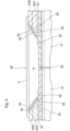
- FIG. 1 illustrates the end portions of a first insulated pipe section 10 and a second insulated pipe section 12 to be joined and provided with a field joint.
- Each pipe section 10 or 12 may comprise a single length of pipe, as supplied from a factory, or a partially assembled pipeline comprising a plurality of pipe sections welded together end-to-end.
- the pipe sections 10 and 12 are of a typical construction, as would be obtained from a pipe coating facility.
- the same reference numerals will be used below and in the drawings to identify their common elements.
- Each pipe section 10, 12 includes a steel pipe 14 having a cylindrical outer surface 16.
- the end 15 of the pipe 14 has an annular connection surface 18 which is at a right angle to the outer surface 16.
- the insulated pipe sections 10, 12 have a line pipe coating comprising a plurality of layers.
- the line pipe coating includes at least a corrosion protection layer 20 on the outer surface 16 of steel pipe 14, and a pipe insulation layer 22 provided over the corrosion protection layer 20.
- insulated pipe sections 10, 12 may include more than one corrosion protection layer or more than one layer of pipe insulation.
- pipe sections 10, 12 may include other types of functional layers, such as thermal barriers, adhesive layers, and outer abrasion-resistant or protective top coats.
- the functional layers of the line pipe coatings of sections 10 and 12 may include those described in above-mentioned US Provisional Patent Application No. 61/863,976 by Wan et al.
- the corrosion protection layer 20 of the line pipe coating is described herein as comprising a single layer, it may instead be comprised of multiple layers of different composition.
- the corrosion protection layer 20 comprises a high temperature corrosion protection material and may be selected from the group comprising epoxy phenolics, polyphenylene sulphides, fluoropolymers, polyimides, or high temperature fusion bonded epoxy (FBE), including modified versions and blends thereof.
- the FBE may be a high-temperature epoxy as defined in above-mentioned US Patent Application No. 14/193,663 by Edmondson et al.
- the high-temperature epoxy may comprise an epoxy novolac-based coating capable of continuous operation at or above about 200°C, wherein epoxy novolac resins comprise epoxy functional groups on a phenol formaldehyde backbone.
- An adhesive layer may optionally be provided to bond the corrosion protection layer 20 to the pipe surface 16 or to a subsequently applied layer.
- the pipe insulation layer 22 comprises a polymer having a thermal conductivity of less than about 0.40 W/mk; for example about 0.10 to 0.35 W/mK; and/or heat resistance at continuous operating temperatures of at least about 200°C.
- the pipe insulation layer 22 may comprise a layer of fluoropolymer as described in above-mentioned US Provisional Patent Application No. 61/863,976 by Wan et al.
- the fluoropolymer may be a fluoroelastomer or a fluorocarbon thermoplastic as described by Wan et al.
- pipe insulation layer 22 of Figure 1 includes a first, innermost layer 22A comprising a fluoropolymer.
- the pipe insulation layer 22 may comprise an elastomer selected from hydrogenated nitrile butadiene rubber (HNBR) and nitrile butadiene rubber (NBR).
- HNBR hydrogenated nitrile butadiene rubber
- NBR nitrile butadiene rubber
- a layer of NBR or HNBR can be applied as a second layer 22B on top of an innermost layer 22A of fluoropolymer.
- a layer of HNBR or a blend of HNBR/fluoropolymer can be used as an innermost layer 22A of pipe insulation in some systems.
- the innermost layer 22A comprises HNBR
- the maximum operating temperature of the system is about 180°C.
- pipe insulation layer 22 includes a second layer of insulation 22B located on top of the first layer 22A, wherein the second layer 22B comprises HNBR.
- the pipe insulation layer 22 may comprise a layer of thermoplastic or an epoxy-modified polymer network, as a further insulating layer and/or as a protective topcoat.
- the thermoplastic or epoxy-modified polymer network layer such as a network epoxy modified urethane or olefin, can be applied as a second layer 22B on top of a first layer 22A which may comprise a fluoropolymer and/or HNBR, as discussed above.
- the thermoplastic or epoxy-modified polymer network may be applied as a third layer 22C on top of the second layer 22B, and may comprise the outermost layer of the line pipe coating.
- the compositions of epoxy-modified polymer networks are further discussed below.
- each of the insulated pipe sections 10, 12 has a bare end portion 24 in which the outer surface 16 of the steel pipe 14 is exposed.
- the bare end portion 24 extends from the end 15 of pipe 14 to a terminal end of either the corrosion protection layer 20 or the pipe insulation layer 22.
- the bare end portions 24 are formed during manufacturing and are provided to avoid damage to the layers 20, 22 when the ends of the insulated pipe sections 10, 12 are heated during welding.
- the lengths of the bare end portions 24 of pipe sections 10, 12 may be the same or different, and depend at least partially on the equipment used for welding and/or field jointing, and on the steel pipe wall thickness, and may be on the order of about 150-1,500 mm.
- the pipe insulation layer 22 of each pipe section 10, 12 has a terminal end 26 which is spaced from the end 15 of pipe 14.
- the pipe insulation layer 22 is provided with a chamfer 28 which commences at the terminal end 26 and slopes radially outwardly and away from the end 15 of pipe 14, the chamfer 28 typically being sloped at an angle of from about 20 to 60 degrees.
- the radially inward-most portion of the chamfer 28, located at the terminal end 26 of the pipe insulation layer 22, is sometimes referred to herein as the "chamfer toe".
- each insulated pipe section 10, 12 may extend past the chamfer toe 26 such that a distance between the terminal end 30 of the corrosion protection layer 20 and the end 15 of pipe 14 is less than a distance between the chamfer toe 26 and the end 15 of pipe 14.
- the bare end portion 24 of each insulated pipe section 10, 12 extends from the end 15 of pipe 14 to the terminal end 30 of the corrosion protection layer 20.
- This construction provides an exposed end portion 32 of the corrosion protection layer 20 which extends beyond the chamfer toe 26, sometimes referred to herein as the "lip" of the corrosion protection layer 20.
- the axial length of lip 32 is typically from about 5-50 mm, typically at least about 10 mm.
- the lip 32 may comprise multiple layers.
- the innermost layer 32A of a multi-layer lip 32 comprises the exposed end portion of the corrosion protection layer 20 described above.
- the multi-layer lip 32 also includes an outer layer 32B of thermal insulation of the same composition as the insulation layer 22, or the first layer 22A thereof, in the case of a multi-layer insulation layer 22.
- the outer layer 32B of lip 32 will typically be integrally formed with the insulation layer 22, for example by leaving a layer of thermal insulation when forming the chamfer 28.
- the layers 32A and 32B may be of substantially the same thickness.
- the multi-layer construction of lip 32 may be used, for example, where the first field joint insulation layer 6, described below, is of the same or similar composition as the insulation layer 22, or the first layer 22A thereof, so as to provide improved bonding between the first layer of field joint insulation 6 and the insulation layer 22 of the line pipe coating.
- the anti-corrosion coating 38 of the field joint coating may be eliminated, with the first layer of field joint insulation 6 being applied directly to the outer surfaces 16 of pipes 10, 12, optionally with the use of an adhesive layer (not shown) between the pipe surface 16 and the first thermal insulation layer 6.
- the bare end portions 24 of the insulated pipe sections 10, 12 may be subjected to a cleaning pretreatment in order to ensure that the outer surfaces of the bare end portions 24 are substantially free from oil, grease, dirt, mill scale, rust, paint and foreign matter, so as to promote bonding with the field joint coating.
- the pretreatment may comprise a blast cleaning of the bare end portions 24, which may be performed as an "off-line" step in the factory, for example as disclosed in above-mentioned US Patent Application No. 12/794,402 by Jackson et al.
- the insulated pipe sections 10, 12, are positioned end-to-end with their annular connection surfaces 18 abutting one another, and are then butt welded together to form a circumferential girth weld 34 as shown in Figure 2 .
- the ends 15 of steel pipes 14 are heated to a sufficiently high temperature for welding and a molten weld filler metal is applied to join the pipes 14 together and to fill any gaps between the annular connection surfaces 18.
- the heated area is permitted to cool.
- the welding step results in the formation of a continuous circumferential weld joint 34 between the annular connection surfaces 18 of steel pipes 14, and this is shown in Figure 2 .
- the steel pipes 14 of pipe sections 10, 12 are locally heated proximate to their ends 15 during the welding operation.
- the lengths of bare end portions 24 are of sufficient lengths to prevent excessive heating of the corrosion protection layer 20 and the pipe insulation layer 22.
- an anti-corrosion coating 38 is applied to the joint area 36 after welding.
- the anti-corrosion coating 38 has a long-term resistance to temperatures from about 150°C to above about 205°C, and may comprise any of the materials mentioned above with reference to the corrosion protection layer 20, and optionally including an adhesive layer.
- the anti-corrosion coating 38 may comprise a silicone elastomer having a long-term resistance to temperatures from about 150°C to above about 205°C.
- the silicone elastomer may be a room temperature vulcanizing (RTV) silicone elastomer comprising polydimethylsiloxane.
- RTV silicone elastomers are curable at ambient and elevated temperatures, i.e. by condensation or addition curing.
- suitable RTV elastomers for use in the anti-corrosion coating include single component (RTV-1) silicone elastomers which are curable by condensation curing by reaction between hydroxyl groups of the elastomer and atmospheric moisture.
- Suitable RTV elastomers also include dual component (RTV-2) silicone elastomers which are curable by condensation curing or by an addition reaction between vinyl functional siloxane polymers and silicon-hydrogen oligomers. Addition curing will proceed at ambient temperature but is significantly faster at elevated temperature. Also, the concentration of oligomer affects curing time, and therefore the curing time of the silicone elastomer can be tailored by controlling the temperature and/or the concentration of oligomer.
- RTV-2 dual component
- silicone elastomers which are curable by condensation curing or by an addition reaction between vinyl functional siloxane polymers and silicon-hydrogen oligomers. Addition curing will proceed at ambient temperature but is significantly faster at elevated temperature. Also, the concentration of oligomer affects curing time, and therefore the curing time of the silicone elastomer can be tailored by controlling the temperature and/or the concentration of oligomer.
- the anti-corrosion coating 38 is applied over the entire joint area 36, including the weld joint 34 and the bare end portions 24, so as to provide a continuous corrosion protection layer in the joint area 36.
- the anti-corrosion coating 38 may be applied by spraying or brushing to a thickness of about 100-2000 micrometers, for example about 500-1500 micrometers.
- the anti-corrosion coating 38 at least partially overlaps the exposed end portions 32 of corrosion protection layers 20.
- the exposed lip 32 of corrosion protection layers 20 may be lightly abraded prior to application of the anti-corrosion coating 38, the abrasion being performed either in the factory or in the field.
- an adhesive may be applied to one or more of the chamfer 28, the chamfer toe 26, and the exposed lip 32 of corrosion protection layer 20, so as to improve adhesion to the anti-corrosion coating 38 and/or to subsequently applied insulation layers.
- one or more of the chamfer 28, the chamfer toe 26, and the exposed lip 32 of corrosion protection layer 20 may be surface activated by flame treatment, corona discharge treatment, or plasma treatment to create reactive functional groups on its outer surface to improve bonding to the anti-corrosion coating 38 and/or to subsequently applied insulation layers.
- the anti-corrosion coating 38 typically does not overlap the chamfers 28 to any significant extent.
- the chamfer 28 may be masked, for example with tape, so as to prevent the anti-corrosion coating 38 from overlapping the chamfer 28.
- An alternate method of masking the chamfers 28 is to at least partially coat them with a chamfer inhibition barrier 50 so as to prevent direct contact between the chamfer 28 and any subsequently applied layers, as further discussed below with reference to Figures 3 , 4 and 5 .
- the chamfer inhibition barrier 50 may comprise a layer of a RTV silicone elastomer which may be the same or different from the RTV silicone elastomer comprising the anti-corrosion coating 38.
- the chamfer inhibition barrier 50 may comprise an RTV-1 silicone elastomer, particularly in a system where the anti-corrosion coating 38 of the field joint comprises a RTV-2 silicone elastomer, since the curing of the RTV-2 elastomer may be inhibited by the chemistry of certain types of polymers used in the line pipe coating, such as fluoropolymers.
- the chamfer inhibition barrier 50 may be applied by spraying or brushing to a thickness of about 100-2000 micrometers, for example about 500-1500 micrometers. Because the chamfer inhibition barrier 50 is applied to prevent inhibition of curing in the anti-corrosion coating 38, it will only need to be applied to the thickness of the anti-corrosion coating 38. Therefore, the chamfer inhibition barrier 50 may only be required over the toe 26 of chamfer 28, as in Figure 3 .
- An adhesive may be applied to the chamfer inhibition barrier 50 to improve adhesion to the anti-corrosion coating 38.
- Such an adhesive layer 52 is shown in Figure 5 and discussed below with reference to Embodiment 3.
- the chamfer inhibition barrier 50 may be surface activated by flame treatment, corona discharge treatment, or plasma treatment to create reactive functional groups on its outer surface to improve bonding to the anti-corrosion coating 38.
- anti-corrosion coating 38 After it is applied to pipes 10, 12, the anti-corrosion coating 38 is at least partly cured prior to further processing.
- anti-corrosion coatings 38 comprising RTV silicone elastomers will eventually cure at ambient temperatures, it may be desired to heat the anti-corrosion coating 38 to accelerate curing. This may be accomplished by selectively pre-heating the steel pipes 10, 12 within the joint area 36 immediately before application of the anti-corrosion coating 38, or by heating the anti-corrosion coating 38 after it is applied.
- the next step is to apply a first field joint insulation layer 6 over the joint area 36 and at least partially covering chamfers 28.
- An adhesive may be applied to the anti-corrosion coating 38 and/or chamfers 28 to improve adhesion to subsequently applied insulation layers.
- the anti-corrosion coating 38 and/or the chamfers 28 may be surface activated by flame treatment, corona discharge treatment, or plasma treatment to create reactive functional groups on its outer surface to improve bonding to the subsequently applied insulation layers.
- the first field joint insulation layer 6 Due to its proximity to the outer surfaces 16 of pipes 10, 12, the first field joint insulation layer 6 has a long-term resistance to temperatures from about 150°C to above about 205°C.
- the first field joint insulation layer 6 is also designed to exhibit adequate compressive creep resistance and modulus at these temperatures, and hence maintain the required thermal insulation properties over the lifetime of the oil and gas recovery project.
- the compositions should be sufficiently ductile to withstand the bending strains experienced by the insulated pipe during reeling and installation operations.
- the first field joint insulation layer 6 comprises a high temperature resistant fluoroelastomer and/or HNBR selected to provide the first field joint insulation layer 6 with one or more of the following properties:
- the first field joint insulation layer 6 may be foamed or solid. Where the first field joint insulation layer 6 is foamed, it may either be a blown foam or a syntactic foam having a degree of foaming of up to about 50%, for example from about 5% to about 30%.
- the first field joint insulation layer 6 is applied at a sufficient thickness to provide the insulated transport conduit with an acceptable heat transfer coefficient (U) for the conditions under which it is to be used, with U typically being in the range from about 1 to about 10 W/m 2 K, for example from about 2 to about 8 W/m 2 K.
- the thickness of the first field joint insulation layer 6 is highly variable, due to the fact that each pipeline system is designed for use under specific conditions of depth, temperature etc., and also depending on whether or not the field joint includes one or more additional layers of thermal insulation. In some embodiments, the thickness of the first field joint insulation layer 6 ranges from about 10 mm to a thickness which is greater than that of the line pipe coating.
- the first field joint insulation layer 6 may comprise a fluoropolymer composition, which provides the first field joint insulation layer 6 with heat resistance at the above-mentioned operating temperatures, resistance to chemicals and harsh environments, strength, processibility etc.
- the fluoropolymer may comprise a crosslinked (vulcanized) fluoroelastomer or a fluorocarbon thermoplastic.
- the fluoropolymer composition of the first field joint insulation layer 6 may either be solid or a syntactic foam, and may comprise any of the compositions disclosed in above-mentioned US Provisional Patent Application No. 61/863,976 by Wan et al.
- suitable fluoropolymer compositions may, for example, comprise copolymers of tetrafluoroethylene (TFE) and propylene, also known as TFE/P or FEPM copolymers, which are fluoroelastomers predominantly comprised of tetrafluoroethylene units (-CF 2 -CF 2 -) and propylene units (-CH 2 -CH(CH 3 )-).
- TFE tetrafluoroethylene
- FEPM copolymers also known as TFE/P or FEPM copolymers, which are fluoroelastomers predominantly comprised of tetrafluoroethylene units (-CF 2 -CF 2 -) and propylene units (-CH 2 -CH(CH 3 )-).
- fluoroelastomers which may be used in the first field joint insulation layer include those known as Type 1 to Type 5 FKMs, including:
- the fluoropolymer may comprise a fluorocarbon thermoplastic such as perfluoroalkoxy (PFA) copolymer of polytetrafluoroethylene and perfluoro alkyl vinyl ether; polytetrafluoroethylene (PTFE); fluorinated ethylene propylene (FEP); a copolymer of tetrafluoroethylene and hexafluoroethylene; and/or polyvinylidene fluoride (PVDF).
- PFA perfluoroalkoxy
- PTFE polytetrafluoroethylene
- FEP fluorinated ethylene propylene
- PVDF polyvinylidene fluoride
- a suitable fluoroelastomer composition for use in the first field joint insulation layer 6 is commercially available from AGC Chemicals (Asahi Glass Co., Ltd.) under the trademark AFLAS TM .
- suitable fluoroelastomer compositions include AFLAS TM 100, AFLAS TM 150, and AFLAS TM 300, based on copolymers having the repeating structure -(CF 2 CF 2 )-(CH 2 CH(CH 3 )) m -; and AFLAS TM 200, based on copolymers having the repeating structure -(CF 2 CF 2 )-(CH 2 CH(CH 3 )) m -(CF 2 CF 2 ) n -.
- AFLAS TM copolymer compositions provide the first field joint insulation layer 6 with high heat resistance and high chemical resistance.
- the fluoropolymer composition is a thermoset material, and does not soften or melt when heated.
- the decomposition temperature of the crosslinked propylene-tetrafluorethylene copolymer is about 415°C.
- fluoropolymer compositions comprising the first field joint insulation layer 6, as discussed above, may also be used in the pipe insulation layer 22 of the line pipe coating.
- the first field joint insulation layer 6 may comprise a silicone elastomer having long-term resistance to temperatures from about 150°C to above about 205°C, including any of the RTV-1 and RTV-2 silicone elastomers mentioned above.
- the first field joint insulation layer 6 may comprise HNBR having long-term resistance to temperatures from about 150°C to about 180°C.
- the first field joint insulation layer 6 may comprise a blend of HNBR with one of the fluoropolymers mentioned above, such blends having long-term resistance to temperatures greater than the maximum for HNBR (about 180°C) and less than the maximum for fluoropolymers (above about 205°C).
- the first field joint insulation layer 6 may be applied to the joint area 36 by casting, wherein an annular mold is applied over the joint area 36 and the mold cavity is filled with the first field joint insulation layer 6 in the form of a molten resin.
- the mold may optionally be left in place over the joint to provide the field joint with an outer shell.
- the field joint insulation may also be applied via wrapping of extruded or pre-prepared sheets or strips, or the application of pre-formed shells, wherein the sheets, strips of shells are either uncured or partially cured when applied to the joint area 36.
- the first field joint insulation layer 6 is applied over the anti-corrosion coating 38.
- the anti-corrosion coating 38 may be provided with an adhesive layer or may be subjected to a surface-activating pre-treatment to improve adhesion with the first field joint insulation layer 6.
- the anti-corrosion coating 38 is eliminated and the first field joint insulation layer 6 is applied directly to the bare pipes 10, 12 in the weld joint area 36, optionally with an adhesive between the pipes 10, 12 and the insulation layer 6.
- the line pipe insulation layer 22 and the field joint insulation layer 38 comprise a fluoropolymer
- the lip 32 includes an outer layer 32B comprised of the line pipe thermal insulation.
- the first field joint insulation layer 6 may be cured immediately upon application to the joint area 36.
- the curing of the first field joint insulation layer 6 may be assisted by the application of heat to the joint area 36.
- the joint area 36 may be pre-heated by induction heating of the steel pipes 10, 12, for example by advancing the pipe sections 10, 12 through an induction heating apparatus which selectively preheats the steel pipe in the joint area 36 immediately before application of the first field joint insulation layer 6.
- the first field joint insulation layer 6 may be cured in operation. In these embodiments, the first field joint insulation layer 6 is left partially or completely uncured after it is applied, and is subsequently cured when the insulated pipeline is heated during use.
- the first field joint insulation layer 6 may be applied as a thermal barrier, so as to only partially fill the volume of the joint area 36.
- the field joint will include at least a second field joint insulation layer 8 applied over the first field joint insulation layer 6.
- the first field joint insulation layer 6 may be surface activated by flame treatment, corona discharge treatment, or plasma treatment to create reactive functional groups on its outer surface to improve bonding to the subsequently applied second layer 8.
- the second field joint insulation layer 8 may not necessarily require the same level of high temperature resistance. Therefore, the composition of the second field joint insulation layer 8 is highly variable.
- the second field joint insulation layer 8 may comprise a thermoplastic, such as conventional polyethylene, polypropylene, polybutylene, polyurethane and copolymers, blends and elastomers thereof.
- the second field joint insulation layer 8 may comprise any of the thermoplastics disclosed in US Patent Application Publication No. US 2009/0159146 A1 by Jackson et al. or US Patent No. 8,397,765 by Jackson et al. .
- the second field joint insulation layer 8 may instead comprise an elastomeric material different from that of the first field joint insulation layer 6, such as a hydrogenated nitrile butadiene rubber (HNBR), nitrile butadiene rubber (NBR), silicone rubber, ethylene propylene diene monomer (EPDM) rubber, or butyl rubber.
- HNBR hydrogenated nitrile butadiene rubber
- NBR nitrile butadiene rubber
- EPDM ethylene propylene diene monomer
- butyl rubber butyl rubber
- the second field joint insulation layer comprises an epoxy-modified polymer network, such as an epoxy-urethane hybrid system or an epoxy-olefin hybrid system.
- an epoxy-modified polymer network such as an epoxy-urethane hybrid system or an epoxy-olefin hybrid system.
- Such systems are sometimes referred to as network epoxy modified urethanes or network epoxy modified olefins.
- These epoxy-modified polymer networks typically have a temperature rating from about 90°C to about 140°C.
- the second field joint insulation layer 8 may be foamed or solid. Where the second field joint insulation layer 8 is foamed, it may either be a blown foam or a syntactic foam having a degree of foaming of up to about 50%, for example from about 5% to about 30%.
- the thickness of the second field joint insulation layer 8 is also highly variable and, in some embodiments, the second field joint insulation layer 8 may extend to a thickness greater than that of the line pipe coating.
- one or more of the field joint insulation layers may also be provided with an additional protective layer, or topcoat 9 comprised of unfoamed polymeric material.
- the topcoat 9 may be prepared from the same or different material as one of the underlying field joint insulation layers 6 and/or 8, or a modified or reinforced version thereof.
- the topcoat 9 may comprise a metal shell.
- the outer protective topcoat 9 may comprise the thermal insulation material blended with suitable polymeric modifiers, compatibilisers, or reinforcing fillers or fibres, or it may comprise a dissimilar, preferably compatible, polymeric material.
- thermal insulation layers may contain additives selected from one or more members of the group comprising inorganic fillers, reinforcing fillers or fibres, nano-fillers, conductive fillers, flame-retardant fillers, antioxidants, heat-stabilisers, process aids, compatibilisers, organic fillers, and pigments.
- a line pipe coating comprising:
- the line pipe coating has a chamfer 28 with an exposed lip 32 of the corrosion protection layer 20 extending at least 10 mm past the chamfer toe 26.
- the chamfers 28 of pipes 10, 12 were optionally masked by applying a chamfer inhibition barrier 50 comprising a silicone elastomer, such as any of the RTV-1 silicone elastomers described above, to at least the toes 26 of chamfers 28.
- the chamfers 28 were preheated to about 100°C before the chamfer inhibition barrier 50 was applied to chamfers 28 by spraying.
- the thickness of the chamfer inhibition barrier 50 was about 1000 micrometers.
- the chamfer inhibition barrier 50 was cured by heating (baking).
- an anti-corrosion coating 38 comprising a silicone elastomer, such as any of the RTV-2 silicone elastomers described above, was then applied to the joint area 36, to at least partially overlaps the lip 32 of the corrosion protection layer 20.
- the anti-corrosion coating has a thickness of about 500 to 1,500 micrometers and is applied by spraying.
- the anti-corrosion coating 38 was cured by heating (baking).
- a first field joint insulation layer 6 in the form of a thermal barrier was then applied over the joint area 36, partially filling the joint area 36 and partially overlapping the chamfers 28.
- the layer 6 comprised a fluoroelastomer composition (AFLAS TM ), which was applied in uncured or partially cured form in the form of a sheet which is wrapped around the joint area 36.
- the fluoroelastomer had a temperature rating of about 205°C and a thickness of about 50 mm.
- the steel pipes 10, 12 were induction heated to at least partially cure the first field joint insulation layer 6.
- this curing step is optional, and the first field joint insulation layer 6 may instead be cured during operation of the pipeline.
- the joint area 36 and chamfers 28 were then pre-heated to about 80°C and a second field joint insulation layer 8 was applied over the first field joint insulation layer 6.
- the second field joint insulation layer 8 was applied by casting in a sheet metal mold to a sufficient thickness to completely fill the joint area 36, completely cover the remainder of chamfers 28, and overlap the outer surface of the line pipe coating.
- the total thickness of the second field joint insulation layer was about 50-60 mm, and the overlap at each end of the joint area 36 was about 8 mm in thickness and about 70 mm in axial length.
- the first field joint insulation layer 6 may be surface activated by flame treatment, corona discharge treatment, or plasma treatment to create reactive functional groups on its outer surface to improve bonding to the subsequently applied second layer 8.
- the surface activation may optionally be used in combination with the heating step discussed above.
- the second field joint insulation layer 8 comprised a network epoxy modified urethane composition having a temperature rating of about 95°C.
- the network epoxy modified urethane composition cures exothermically and no external heat was required to cure the second field joint insulation layer 8.
- the second field joint insulation layer 8 may have comprised a network epoxy modified olefin composition.
- the chamfers 28 of pipes 10, 12 were masked by applying a chamfer inhibition barrier 50 comprising a silicone elastomer, such as any of the RTV-1 silicone elastomers described above.
- the chamfers 28 were preheated to about 100°C prior to application of the chamfer inhibition barrier 50 by spraying to a thickness of about 1000 micrometers.
- the chamfer inhibition barrier 50 was fully cured by heating (baking).
- the adhesive layer 52 was then applied over the chamfers 28.
- the adhesive layer comprised a RTV-1 silicone elastomer was applied to chamfers 28 by spraying to a thickness of about 1000 micrometers.
- the chamfer inhibition barrier was semi-cured by heating (baking).
- a first field joint insulation layer 6 was then applied over the adhesive layer 52 and over the entire joint area 36.
- the first field joint insulation layer 6 comprised a silicone elastomer, such as any of the RTV-2 silicone elastomers described above, and was applied by casting in a sheet metal mold to a sufficient thickness to completely fill the joint area 36 and completely cover the chamfers 28, so as to be substantially flush with the outer surface of the line pipe coating.
- the total thickness of the first field joint insulation layer 6 was about 80-100 mm.
- a polyethylene heat shrink sleeve was then applied over the first insulation layer 6 as a protective shield or top coat 9.
- the sleeve overlapped each end of the joint area 36 by an axial length of about 70 mm.
- the chamfers 28 of pipes 10, 12 were partially masked by applying a chamfer inhibition barrier 50 comprising a silicone elastomer, such as any of the RTV-1 silicone elastomers described above.
- the chamfers 28 were preheated to about 100°C prior to application of the chamfer inhibition barrier 50 by spraying to a thickness of about 1000 micrometers.
- the chamfer inhibition barrier 50 was fully cured by heating (baking).
- the adhesive layer 52 was then applied over the masked portions of chamfers 28.
- the adhesive layer 52 comprised a RTV-1 silicone elastomer and was applied to chamfers 28 by spraying to a thickness of about 1000 micrometers.
- the adhesive layer 52 was semi-cured by heating (baking).
- the first field joint insulation layer 6 was then applied over the adhesive layer.
- the first field joint insulation layer 6 comprised a silicone elastomer, such as any of the RTV-2 silicone elastomers described above, and was applied by casting in a sheet metal mold to partially fill the joint area 36 and partially overlap the chamfers 28 to a thickness of about 50-60 mm.
- a second field joint insulation layer 8 was then applied over the first insulation layer 6.
- the first layer 6 Prior to applying the second layer 8, the first layer 6 was preheated to about 80°C to remove surface moisture and to help cure the subsequently applied second layer 8.
- the first field joint insulation layer 6 was surface activated so as to ionize the silicone to create reactive functional groups on the surface of the first layer 6 and improve adhesion to the subsequently applied second layer 8.
- the surface activation comprised flame treatment, corona discharge treatment, or plasma treatment.
- the second field joint insulation layer 8 comprised a network epoxy modified urethane composition having a temperature rating of about 95°C.
- the second field joint insulation layer 8 was applied by casting in a sheet metal mold to a sufficient thickness to completely fill the joint area 36, completely cover the remainder of chamfers 28, and overlap the outer surface of the line pipe coating.
- the second field joint insulation layer 8 may have comprised a network epoxy modified olefin composition, and/or the sheet metal mold may have been left in place to provide an outer metal shell over the field joint.
- the total thickness of the second field joint insulation layer 8 was about 50 mm, and the overlap at each end of the joint area 36 was about 8 mm in thickness and about 70 mm in axial length.
- adhesive layers are mentioned herein, it will be appreciated that the composition of the adhesive layer will depend at least partly on the compositions of the layers being bonded together.
- adhesives used herein may be polymers or reactive systems with functionalities having mutual affinity to the layers being bonded, the functionalities being specific to the chemical composition of the layers being bonded.
- the adhesive should provide a bond strength sufficient to promote cohesive failure between the layers being bonded.
- the adhesive layer between adjacent thermal insulation layers and between a thermal insulation layer and one or more of adjacent layers may, for example, comprise a grafted polymer or copolymer, or polymer blend with one or more moieties compatible with each of the individual layers to be bonded.
- the first thermal insulation layer 6 may be bonded to an adjacent layer by an adhesive which bonds to the fluoroelastomer during vulcanization.
- an adhesive may be a liquid adhesive specially formulated for vulcanization/bonding of elastomers to steel and other rigid substrates, such as those disclosed in above-mentioned US Provisional Patent Application No. 61/863,976 by Wan et al.
Landscapes
- Engineering & Computer Science (AREA)
- General Engineering & Computer Science (AREA)
- Mechanical Engineering (AREA)
- Physics & Mathematics (AREA)
- Optics & Photonics (AREA)
- Laminated Bodies (AREA)
- Thermal Insulation (AREA)
- Protection Of Pipes Against Damage, Friction, And Corrosion (AREA)
Claims (16)
- Procédé de formation d'un raccord entre deux sections de tuyau isolé (10, 12), le procédé comprenant :(a) fournir une première section de tuyau isolé (10) et une deuxième section de tuyau isolé (12), dans lequel chacune des sections de tuyau isolé (10, 12) comprend :(i) un tuyau en acier (14) ayant une surface externe (16) et une extrémité (15), dans lequel une surface de raccordement annulaire (18) est située à ladite extrémité (15) du tuyau en acier (14),(ii) un revêtement de protection anti-corrosion (20) fourni sur la surface externe (16) du tuyau en acier (14), dans lequel une extrémité terminale du revêtement de protection anti-corrosion (20) est espacée de l'extrémité (15) du tuyau (14) ; et(iii) une couche d'isolation de tuyau (22) fournie sur le revêtement de protection anti-corrosion (20), dans lequel une extrémité terminale (26) de la couche d'isolation de tuyau (22) est espacée de l'extrémité (15) du tuyau (14), et dans lequel la couche d'isolation de tuyau (22) comprend une composition polymère ayant une conductivité thermique de moins d'environ 0,40 W/mk, et/ou une résistance à la chaleur à des températures de fonctionnement continu d'environ 150 °C jusqu'à plus d'environ 205 °C ;dans lequel le revêtement de protection anti-corrosion (20) et la couche d'isolation de tuyau (22) comprennent ensemble un revêtement de tube de canalisation des sections de tuyau isolé (10, 12) ; etdans lequel chacune des sections de tuyau isolé (10, 12) a une partie d'extrémité nue (24) dans laquelle la surface externe (16) du tuyau en acier (14) est exposée, la partie d'extrémité nue (24) s'étendant de l'extrémité (15) du tuyau en acier (14) jusqu'à l'extrémité terminale de soit le revêtement de protection anti-corrosion (20) soit la couche d'isolation de tuyau (22) ;(b) souder le tuyau en acier (14) de la première partie de tuyau isolé (10) au tuyau en acier (14) de la deuxième partie de tuyau isolé (12), de manière à former un raccord de soudure circonférentiel (34) entre les surfaces de raccordement annulaires (18) des tuyaux en acier (14), et de manière à former une zone de raccord continu (36) qui comprend le raccord de soudure circonférentiel (34) et les parties d'extrémité nues (24) des sections de tuyau isolé (10, 12) ;(c) appliquer une première couche d'isolation de raccord (6) au-dessus de la zone de raccord (36),caractérisé en ce que la première couche d'isolation de raccord (6) comprend une composition polymère ayant une résistance à la chaleur à des températures de fonctionnement continu d'environ 150 °C jusqu'à plus d'environ 205 °C ;et en ce que le procédé comprend en outre l'étape consistant à :
(d) appliquer une deuxième couche d'isolation de raccord au-dessus de la première couche d'isolation de raccord, dans lequel la deuxième couche d'isolation de raccord comprend une composition ayant du thermoplastique ayant une résistance à la chaleur à des températures de fonctionnement continu dans une plage d'environ 90 °C jusqu'à plus d'environ 140 °C. - Procédé selon la revendication 1, caractérisé en ce que la deuxième couche d'isolation de raccord (8) comprend un réseau polymère modifié époxy.
- Procédé selon la revendication 2, caractérisé en ce que le réseau polymère modifié époxy comprend un réseau uréthane modifié époxy ayant une résistance à la chaleur à des températures de fonctionnement continu dans une plage d'environ 90 °C à environ 100 °C.
- Procédé selon l'une quelconque des revendications 1 à 3, caractérisé en ce que la première et la deuxième couche d'isolation de raccord (6, 8) ont une épaisseur combinée qui est supérieure à celle du revêtement de tube de canalisation, et dans lequel la deuxième couche d'isolation de raccord (8) chevauche le revêtement de tube de canalisation des deux côtés de la zone de raccord (36).
- Procédé selon l'une quelconque des revendications 1 à 4, caractérisé en ce que la couche d'isolation de tuyau (22) comprend une couche d'une composition de fluoroélastomère.
- Procédé selon la revendication 5, caractérisé en ce que la couche d'isolation de tuyau (22) comprend en outre une couche d'une composition d'élastomère différente de la composition de fluoroélastomère.
- Procédé selon la revendication 1, caractérisé en ce qu'une lèvre (32) de la couche de protection anti-corrosion (20) fait saillie au-delà de l'extrémité terminale (26) de la couche d'isolation de tuyau (22) de chacune des sections de tuyau isolé (10, 12) ;dans lequel la première couche d'isolation de raccord (6) est appliquée directement aux parties d'extrémité nues (24) des sections de tuyau isolé (10, 12) dans ladite zone de raccord (36)dans lequel la première couche d'isolation de raccord (6) chevauche au moins partiellement ladite lèvre (32) ;dans lequel la lèvre (32) comprend une couche externe (32B) comprenant une isolation thermique de la même composition qu'une couche la plus intérieure (22A, 22) de la couche d'isolation de tuyau (22) ; etdans lequel la première couche d'isolation de raccord (6) et la couche externe (32B) de la lèvre (32) sont constituées chacune d'un fluoroélastomère.
- Procédé selon l'une quelconque des revendications 1 à 7, caractérisé en comprenant en outre l'étape consistant à appliquer une couche adhésive ou à faire un prétraitement d'activation de surface sur une ou plusieurs couches du raccord, de manière à améliorer l'adhésion entre lesdites couches, dans lequel le prétraitement d'activation de surface est sélectionné parmi un traitement à la flamme, un traitement à décharge corona et un traitement au plasma.
- Conduit isolé, comprenant :(a) une première section de tuyau isolé (10) et une deuxième section de tuyau isolé (12), dans lequel chacune des sections de tuyau isolé (10, 12) comprend :(i) un tuyau en acier (14) ayant une surface externe (16) et une extrémité (15), dans lequel une surface de raccordement annulaire (18) est située à ladite extrémité (15) du tuyau en acier (14),(ii) un revêtement de protection anti-corrosion (20) fourni sur la surface externe (16) du tuyau en acier (14), dans lequel une extrémité terminale du revêtement de protection anti-corrosion (20) est espacée de l'extrémité (15) du tuyau (14) ; et(iii) une couche d'isolation de tuyau (22) fournie sur le revêtement de protection anti-corrosion (20), dans lequel une extrémité terminale (26) de la couche d'isolation de tuyau (22) est espacée de l'extrémité (15) du tuyau (14), et dans lequel la couche d'isolation de tuyau (22) comprend une composition polymère ayant une conductivité thermique de moins d'environ 0,40 W/mk, et/ou une résistance à la chaleur à des températures de fonctionnement continu d'environ 150 °C jusqu'à plus d'environ 205 °C, dans lequel le revêtement de protection anti-corrosion (20) et la couche d'isolation de tuyau (22) comprennent ensemble un revêtement de tube de canalisation des sections de tuyau isolé (10, 12) ; et(iv) un raccord de soudure circonférentiel (34) entre les surfaces de raccordement annulaires (18) de tuyaux en acier (14), dans lequel une zone de raccord continu (36) comprend le raccord de soudure circonférentiel (34) et les parties d'extrémité nues (24) des sections de tuyau isolé (10, 12) ;(b) un raccord comprenant :(i) une première couche d'isolation de raccord (6) sur la zone de raccord (36) ;caractérisé en ce que la première couche d'isolation de raccord (6) comprend une composition polymère ayant une résistance à la chaleur à des températures de fonctionnement continu d'environ 150 °C jusqu'à plus de 205 °C ; eten ce que le raccord comprend en outre :
(ii) une deuxième couche d'isolation de raccord (8) au-dessus de la première couche d'isolation de raccord (6), dans lequel la deuxième couche d'isolation de raccord (8) comprend une composition polymère ayant du thermoplastique ayant une résistance à la chaleur à des températures de fonctionnement continu dans la plage d'environ 90 °C jusqu'à plus d'environ 140 °C. - Conduit isolé selon la revendication 9, caractérisé en ce que la deuxième couche d'isolation de raccord (8) comprend un réseau polymère modifié époxy.
- Conduit isolé selon la revendication 10, caractérisé en ce que le réseau polymère modifié époxy comprend un réseau uréthane modifié époxy ayant une résistance à la chaleur à des températures de fonctionnement continu dans une plage d'environ 90 °C à environ 100 °C.
- Conduit isolé selon l'une quelconque des revendications 9 à 11, caractérisé en ce que la première et la deuxième couche d'isolation de raccord (6, 8) ont une épaisseur combinée qui est supérieure à celle du revêtement de tube de canalisation et dans lequel la deuxième couche d'isolation de raccord (8) chevauche le revêtement de tube de canalisation des deux côtés de la zone de raccord (36).
- Conduit isolé selon l'une quelconque des revendications 9 à 12, caractérisé en ce que la couche d'isolation de tuyau (22) comprend une couche d'une composition de fluoroélastomère.
- Conduit isolé selon la revendication 13, caractérisé en ce que la couche d'isolation de tuyau (22) comprend en outre une couche d'une composition d'élastomère différente de la composition de fluoroélastomère.
- Conduit isolé selon la revendication 9, caractérisé en ce qu'une lèvre (32) de la couche de protection anti-corrosion (20) fait saillie au-delà de l'extrémité terminale (26) de la couche d'isolation de tuyau (22) de chacune des sections de tuyau isolé (10, 12) ;dans lequel la première couche d'isolation de raccord est fournie directement sur les parties d'extrémité nues (24) des sections de tuyau isolé (10, 12) dans ladite zone de raccord (36)dans lequel la première couche d'isolation de raccord (6) chevauche au moins partiellement ladite lèvre (32) ; eten ce que la lèvre (32) comprend optionnellement une couche externe (32B) comprenant une isolation thermique de la même composition qu'une couche la plus intérieure (22A, 22) de la couche d'isolation de tuyau (22) ;en ce que la première couche d'isolation de raccord (6) et la couche externe (32B) de la lèvre (32) sont constituées chacune d'un fluoroélastomère.
- Conduit isolé selon l'une quelconque des revendications 9 à 15, caractérisé en comprenant en outre une ou plusieurs couches adhésives, chacune desquelles est appliquée entre des couches adjacentes du raccord, de manière à améliorer l'adhésion entre lesdites couches ; ou
une ou plusieurs couches du raccord ont été soumises à un prétraitement d'activation de surface sélectionné parmi un traitement à la flamme, un traitement à décharge corona et un traitement au plasma.
Applications Claiming Priority (3)
| Application Number | Priority Date | Filing Date | Title |
|---|---|---|---|
| US201361863976P | 2013-08-09 | 2013-08-09 | |
| US201462021751P | 2014-07-08 | 2014-07-08 | |
| PCT/CA2014/050750 WO2015017938A1 (fr) | 2013-08-09 | 2014-08-08 | Raccords à haute température |
Publications (3)
| Publication Number | Publication Date |
|---|---|
| EP3030824A1 EP3030824A1 (fr) | 2016-06-15 |
| EP3030824A4 EP3030824A4 (fr) | 2017-01-11 |
| EP3030824B1 true EP3030824B1 (fr) | 2024-03-27 |
Family
ID=52447565
Family Applications (2)
| Application Number | Title | Priority Date | Filing Date |
|---|---|---|---|
| EP14835360.0A Active EP3030824B1 (fr) | 2013-08-09 | 2014-08-08 | Procédé pour leur fabrication et raccords à haute température |
| EP14834869.1A Active EP3030823B1 (fr) | 2013-08-09 | 2014-08-08 | Conduites isolées à haute température |
Family Applications After (1)
| Application Number | Title | Priority Date | Filing Date |
|---|---|---|---|
| EP14834869.1A Active EP3030823B1 (fr) | 2013-08-09 | 2014-08-08 | Conduites isolées à haute température |
Country Status (5)
| Country | Link |
|---|---|
| US (4) | US9810366B2 (fr) |
| EP (2) | EP3030824B1 (fr) |
| MX (2) | MX381467B (fr) |
| MY (1) | MY186034A (fr) |
| WO (2) | WO2015017937A1 (fr) |
Families Citing this family (44)
| Publication number | Priority date | Publication date | Assignee | Title |
|---|---|---|---|---|
| US20100183837A1 (en) * | 2007-03-07 | 2010-07-22 | Arkema France | Use of a polyamide based composition for flexible pipes for conveying crude oil or gas and flexible pipe using such composition |
| FR2991213B1 (fr) * | 2012-06-05 | 2015-07-03 | Alstom Hydro France | Procede de soudage de deux bords d'une ou plusieurs pieces en acier l'un a l'autre et conduite forcee obtenue par un tel procede. |
| US10480862B2 (en) * | 2013-05-23 | 2019-11-19 | Crc-Evans Pipeline International, Inc. | Systems and methods for use in welding pipe segments of a pipeline |
| US11767934B2 (en) | 2013-05-23 | 2023-09-26 | Crc-Evans Pipeline International, Inc. | Internally welded pipes |
| CA2915486C (fr) | 2013-06-24 | 2023-01-03 | Materia, Inc. | Isolation thermique |
| EP3030824B1 (fr) | 2013-08-09 | 2024-03-27 | ShawCor Ltd. | Procédé pour leur fabrication et raccords à haute température |
| CA2942810C (fr) | 2014-03-28 | 2021-02-16 | Public Joint Stock Company "Transneft" | Procede d'isolation thermique de connexions soudees de tubes prealablement isoles |
| US11685090B2 (en) | 2014-10-17 | 2023-06-27 | Shawcor Ltd. | Method of coating a field joint |
| MY186534A (en) * | 2014-10-17 | 2021-07-25 | Shawcor Ltd | Flush field joint |
| MX394845B (es) * | 2015-01-23 | 2025-03-24 | Shawcor Ltd | Junta de montaje de dos capas moldeada por inyección para aplicaciones de tubería. |
| US10281079B2 (en) | 2015-08-31 | 2019-05-07 | General Electric Company | Insulated fluid conduit |
| US9903525B2 (en) | 2015-08-31 | 2018-02-27 | General Electronic Company | Insulated fluid conduit |
| US9938799B2 (en) * | 2015-09-03 | 2018-04-10 | Fmc Technologies, Inc. | High temperature insulation system and method |
| CA3003739C (fr) * | 2015-11-02 | 2022-06-14 | Agc Chemicals Americas Inc. | Conduite isolee comprenant une composition de polymere fluore pour l'utilisation comme couche d'isolation thermique |
| CN105240653A (zh) * | 2015-11-11 | 2016-01-13 | 浙江创想节能科技有限公司 | 一种耐超高温可拆卸式保温套 |
| CN105333240A (zh) * | 2015-11-11 | 2016-02-17 | 肖练 | 一种具有良好耐候性的预制油气管线 |
| CN107289234B (zh) * | 2016-03-31 | 2020-04-10 | 中国石油天然气股份有限公司 | 一种保温管道防腐保温层修复结构及修复方法 |
| US10746342B2 (en) * | 2016-05-31 | 2020-08-18 | Seal For Life Industries Us Llc | Closure patch |
| US11458571B2 (en) | 2016-07-01 | 2022-10-04 | Crc-Evans Pipeline International, Inc. | Systems and methods for use in welding pipe segments of a pipeline |
| CN108071895A (zh) * | 2016-11-16 | 2018-05-25 | 江苏瑞凌新能源科技有限公司 | 一种直埋式保温管 |
| RU2699152C2 (ru) * | 2017-07-11 | 2019-09-03 | Общество с ограниченной ответственностью "СТЕКЛОНиТ Менеджмент" | Система изоляции в трассовых условиях монтажных стыков смежных трубопроводов с изоляционным покрытием |
| CN112135732B (zh) * | 2018-05-14 | 2023-06-02 | 大金工业株式会社 | 层积体和管 |
| BR112020025080A2 (pt) * | 2018-06-12 | 2021-03-23 | National Oilwell Varco Denmark I/S | método para a produção de um tubo flexível e tubo flexível |
| DE102018115506A1 (de) * | 2018-06-27 | 2020-01-02 | Minimax Viking Research & Development Gmbh | Verfahren zum Herstellen eines Rohrleitungselements, insbesondere eines Rohrleitungselements einer Feuerlöschanlage, Rohrleitungselement und Rohrleitungssystem im selbigen |
| EP3993991B1 (fr) * | 2019-07-01 | 2025-05-21 | Saint-Gobain Performance Plastics Corporation | Raccordement de profilés |
| CN110425013A (zh) * | 2019-07-15 | 2019-11-08 | 天津国康泰节能科技有限公司 | 一种汽轮机可拆卸节能外衣 |
| US20220268375A1 (en) * | 2019-07-25 | 2022-08-25 | Shawcor Ltd. | Multi-layer coated steel pipe comprising an adnesive or epoxy layer |
| KR102823017B1 (ko) * | 2019-12-27 | 2025-06-23 | 생-고뱅 퍼포먼스 플라스틱스 코포레이션 | 프로파일 연결 |
| US11536946B2 (en) * | 2020-03-17 | 2022-12-27 | Baker Hughes Holdings Llc | High temperature cooling tube for borescope |
| KR102927869B1 (ko) | 2020-03-20 | 2026-02-20 | 생-고뱅 퍼포먼스 플라스틱스 코포레이션 | 멸균 밀봉 장치 |
| EP4171920A4 (fr) | 2020-06-19 | 2024-11-06 | Saint-Gobain Performance Plastics Corporation | Article composite et procédé de formation d'un article composite |
| US11608940B2 (en) | 2020-09-01 | 2023-03-21 | Saudi Arabian Oil Company | Passive thermal diode for transportation pipelines using contact switch based on polymer thermal expansion (PTE-PTD) |
| US11402051B2 (en) | 2020-09-01 | 2022-08-02 | Saudi Arabian Oil Company | System for installing insulation sleeves on pipelines |
| US11359759B2 (en) * | 2020-09-01 | 2022-06-14 | Saudi Arabian Oil Company | Passive thermal diode for transportation pipelines using contact switch based on shape memory polymer (SMP-PTD) |
| CN112212075B (zh) * | 2020-10-14 | 2022-02-15 | 浙江世润建创科技发展有限公司 | 钢管穿越河道的穿越结构的施工方法 |
| KR102478502B1 (ko) * | 2020-12-08 | 2022-12-19 | 주식회사 뉴보텍 | 금속수지 복합관의 제조 방법 및 이에 의해 제조된 금속수지 복합관 |
| CN112856054A (zh) * | 2021-02-04 | 2021-05-28 | 辽宁宇航钢塑管制造有限公司 | 硬质聚氨酯泡沫塑料防腐保温管及其制备工艺 |
| CN113339594A (zh) * | 2021-05-17 | 2021-09-03 | 苏州佳通科技股份有限公司 | 一种耐磨隔热pe硅芯管 |
| US11548784B1 (en) | 2021-10-26 | 2023-01-10 | Saudi Arabian Oil Company | Treating sulfur dioxide containing stream by acid aqueous absorption |
| US12116326B2 (en) | 2021-11-22 | 2024-10-15 | Saudi Arabian Oil Company | Conversion of hydrogen sulfide and carbon dioxide into hydrocarbons using non-thermal plasma and a catalyst |
| US11926799B2 (en) | 2021-12-14 | 2024-03-12 | Saudi Arabian Oil Company | 2-iso-alkyl-2-(4-hydroxyphenyl)propane derivatives used as emulsion breakers for crude oil |
| US12179129B2 (en) | 2021-12-14 | 2024-12-31 | Saudi Arabian Oil Company | Synergetic solvent for crude oil emulsion breakers |
| CN116576340B (zh) * | 2023-07-11 | 2023-09-12 | 河北海润管道制造有限公司 | 一种防腐保温管道 |
| WO2026050314A1 (fr) * | 2024-08-26 | 2026-03-05 | Parker-Hannifin Corporation | Mousses polymères de perfluoroalcoxy (pfa) thermiquement isolantes et légères, tubes thermiquement isolés les comprenant, et leurs procédés de fabrication et d'utilisation |
Family Cites Families (49)
| Publication number | Priority date | Publication date | Assignee | Title |
|---|---|---|---|---|
| US3508946A (en) * | 1964-04-09 | 1970-04-28 | Dow Corning | Pipe coated with epoxy resin composition cured with extra-coordinate silicon complex and process for coating said pipe |
| US3422855A (en) * | 1965-11-17 | 1969-01-21 | Dow Corning | High temperature fluid conduit |
| US3685546A (en) * | 1969-06-09 | 1972-08-22 | Wavin Bv | Thermally insulated pipe |
| US3992237A (en) * | 1970-02-12 | 1976-11-16 | Industriele Onderneming Wavin N.V. | Connections for insulated pipes |
| NL154317B (nl) * | 1970-08-06 | 1977-08-15 | Walvin B V | Verbinding voor geisoleerde buizen of buisdelen. |
| JPS539848A (en) | 1976-07-16 | 1978-01-28 | Asahi Glass Co Ltd | Heat treatment of fluorine-containing elastomers |
| US4341842A (en) * | 1980-06-30 | 1982-07-27 | General Electric Company | Method of coating automotive parts with silicone compositions |
| US4415184A (en) * | 1981-04-27 | 1983-11-15 | General Electric Company | High temperature insulated casing |
| JPS59182836A (ja) | 1983-04-01 | 1984-10-17 | Asahi Glass Co Ltd | 含フツ素エラストマ−組成物およびそれよりなるライニング材 |
| US4606953A (en) * | 1983-06-23 | 1986-08-19 | Nippon Steel Corporation | Polypropylene coated steel pipe |
| FR2557671B1 (fr) * | 1983-12-28 | 1986-08-01 | Hutchinson Sa | Perfectionnements apportes aux moyens d'isolation thermique de tuyauteries soumises a des contraintes thermiques, hydrostatiques et mecaniques et a leur mise en place, et procedes de realisation desdits moyens d'isolation |
| NO844213L (no) | 1984-10-22 | 1986-04-23 | Viking Mjondalen As | Fremgangsmaate ved skjoeting av korrosjonsbeskyttet roerledning og roerlengde til bruk ved utfoerelse av fremgangsmaaten. |
| CA1265288A (fr) | 1984-11-22 | 1990-01-30 | E. I. Du Pont De Nemours And Company | Compositions de fluoroelastomere etuvable |
| US4746147A (en) * | 1987-04-09 | 1988-05-24 | Ecw, Inc. | Pipe joint |
| GB8812513D0 (en) * | 1988-05-26 | 1988-06-29 | Regal Technology Uk Ltd | Field joint insulation for insulated pipelines |
| US5143122A (en) | 1990-09-11 | 1992-09-01 | Bundy Corporation | Composite flexible conduit assembly |
| EP0660024B1 (fr) | 1993-12-27 | 1997-10-22 | Sumitomo Chemical Company, Limited | Tuyau à revêtement de résine |
| KR100188298B1 (ko) | 1995-01-30 | 1999-06-01 | 모리시따요오이찌 | 단열발포체 및 그 제조방법 |
| GB9613973D0 (en) * | 1996-07-03 | 1996-09-04 | Bredero Price Services | Improvements in or relating to field joints |
| FR2759018B1 (fr) * | 1997-02-05 | 1999-05-14 | Hutchinson | Produit composite thermoplastique-elastomere, tel par exemple qu'un tuyau de transport de refrigerant pour circuit de climatisation |
| DE69828031T2 (de) * | 1997-02-19 | 2005-12-01 | Daikin Industries, Ltd. | Gummiverbundstoff und verwendungen davon |
| US20050182157A1 (en) | 2004-02-14 | 2005-08-18 | Csaba Truckai | Polymer composite and method of making |
| GB2405456B (en) | 2003-08-23 | 2007-10-10 | Petrotechnik Ltd | Improved pipe |
| GB0322529D0 (en) | 2003-09-26 | 2003-10-29 | Oceaneering Internat Services | Fluid conduit |
| US7351769B2 (en) | 2004-01-26 | 2008-04-01 | Freudenberg-Nok General Partnership | Dynamic vulcanization of elastomers with in-situ polymerization |
| WO2006058270A1 (fr) | 2004-11-24 | 2006-06-01 | E.I. Dupont De Nemours And Company | Tubes chemises-gaines pour milieu acide |
| US8127800B2 (en) | 2005-02-28 | 2012-03-06 | Parker-Hannifin Corporation | Fire protective hose assembly |
| EP2069426B1 (fr) * | 2006-09-11 | 2010-08-25 | DSM IP Assets B.V. | Matériau d'isolation thermique |
| GB0716750D0 (en) | 2007-08-29 | 2007-10-10 | Pipeline Induction Heat Ltd | Improvements in coating pipes |
| WO2009086068A2 (fr) | 2007-12-21 | 2009-07-09 | 3M Innovative Properties Company | Fluoropolymères amorphes durcissables à basse température |
| US8714206B2 (en) | 2007-12-21 | 2014-05-06 | Shawcor Ltd. | Styrenic insulation for pipe |
| EP2318749B1 (fr) * | 2008-07-25 | 2020-11-04 | ShawCor Ltd. | Isolation résistante à la haute température pour tuyau |
| US8397765B2 (en) * | 2008-07-25 | 2013-03-19 | Shawcor Ltd. | High temperature resistant insulation for pipe |
| US8176943B2 (en) | 2008-11-21 | 2012-05-15 | Parker-Hannifin Corporation | High temperature fire sleeve |
| EP2343183B1 (fr) * | 2010-01-07 | 2015-07-22 | Armacell Enterprise GmbH & Co. KG | Isolation élastomère contre les basses températures |
| US9193879B2 (en) | 2010-02-17 | 2015-11-24 | Baker Hughes Incorporated | Nano-coatings for articles |
| US8857700B2 (en) | 2010-06-04 | 2014-10-14 | Shawcor Ltd. | Low temperature method for forming field joints on undersea pipelines |
| DE102010017305A1 (de) * | 2010-06-09 | 2011-12-15 | Contitech Elastomer-Beschichtungen Gmbh | Isolationsmaterial und Verfahren zur Isolation |
| BR112012032511A2 (pt) | 2010-06-23 | 2019-09-24 | Shell Int Research | aparelho antiaderente, e, método para produzir hidrocarbonetos. |
| JP5833657B2 (ja) | 2010-09-24 | 2015-12-16 | グリーン, ツイード オブ デラウェア, インコーポレイテッド | 高温への適用に適したフッ素含有エラストマー組成物 |
| US20120202047A1 (en) | 2011-02-07 | 2012-08-09 | Baker Hughes Incorporated | Nano-coatings for articles |
| BR112013029049B1 (pt) * | 2011-05-13 | 2020-11-03 | National Oilwell Varco Denmark I/S | tubo flexível não ligado, e, sistema de tubo flexível |
| EP2573443B1 (fr) * | 2011-09-21 | 2014-03-05 | ContiTech Elastomer-Beschichtungen GmbH | Procédé d'isolation de composants à l'aide d'un matériau isolant souple |
| NL2007737C2 (en) | 2011-11-07 | 2013-05-08 | Bluemarine Offshore Yard Service B V | Method for filling a gap in the coating of a pipeline coated with a coating, preferably a thermo-insulating coating. |
| US20130171367A1 (en) | 2011-12-30 | 2013-07-04 | Grzegorz Jan Kusinski | Coating compositions, applications thereof, and methods of forming |
| NL2008638C2 (en) | 2012-04-13 | 2013-10-16 | Heerema Marine Contractors Nl | Method of manufacturing a field joint coating. |
| WO2014028444A2 (fr) * | 2012-08-15 | 2014-02-20 | Powdermet, Inc. | Isolation d'une ligne d'écoulement à haute température |
| US20140311614A1 (en) | 2013-02-28 | 2014-10-23 | Shawcor Ltd. | High temperature resistant polysulfone insulation for pipe |
| EP3030824B1 (fr) | 2013-08-09 | 2024-03-27 | ShawCor Ltd. | Procédé pour leur fabrication et raccords à haute température |
-
2014
- 2014-08-08 EP EP14835360.0A patent/EP3030824B1/fr active Active
- 2014-08-08 MX MX2016001579A patent/MX381467B/es unknown
- 2014-08-08 WO PCT/CA2014/050749 patent/WO2015017937A1/fr not_active Ceased
- 2014-08-08 MY MYPI2016700185A patent/MY186034A/en unknown
- 2014-08-08 MX MX2016001581A patent/MX390222B/es unknown
- 2014-08-08 EP EP14834869.1A patent/EP3030823B1/fr active Active
- 2014-08-08 US US14/455,213 patent/US9810366B2/en active Active
- 2014-08-08 US US14/454,818 patent/US20150041018A1/en not_active Abandoned
- 2014-08-08 WO PCT/CA2014/050750 patent/WO2015017938A1/fr not_active Ceased
-
2015
- 2015-09-30 US US14/870,602 patent/US10161556B2/en active Active
- 2015-11-30 US US14/954,545 patent/US9791091B2/en not_active Expired - Fee Related
Also Published As
| Publication number | Publication date |
|---|---|
| MX2016001581A (es) | 2016-05-02 |
| WO2015017938A1 (fr) | 2015-02-12 |
| EP3030823A4 (fr) | 2016-12-28 |
| US20160018049A1 (en) | 2016-01-21 |
| MY186034A (en) | 2021-06-15 |
| EP3030824A4 (fr) | 2017-01-11 |
| US9791091B2 (en) | 2017-10-17 |
| MX381467B (es) | 2025-03-12 |
| EP3030823B1 (fr) | 2025-07-30 |
| EP3030824A1 (fr) | 2016-06-15 |
| US20160109052A1 (en) | 2016-04-21 |
| MX390222B (es) | 2025-03-19 |
| MX2016001579A (es) | 2016-05-02 |
| US20150041017A1 (en) | 2015-02-12 |
| EP3030823A1 (fr) | 2016-06-15 |
| US20150041018A1 (en) | 2015-02-12 |
| US9810366B2 (en) | 2017-11-07 |
| EP3030823C0 (fr) | 2025-07-30 |
| US10161556B2 (en) | 2018-12-25 |
| WO2015017937A1 (fr) | 2015-02-12 |
Similar Documents
| Publication | Publication Date | Title |
|---|---|---|
| US9810366B2 (en) | High temperature field joints | |
| AU2011261132B2 (en) | Low temperature method and system for forming field joints on undersea pipelines | |
| US11313507B2 (en) | Field joint coating | |
| US11168827B2 (en) | Method of and system for coating a field joint of a pipe | |
| CN108284659B (zh) | 具有多层中间层的热塑性复合材料管材 | |
| WO2014028444A2 (fr) | Isolation d'une ligne d'écoulement à haute température | |
| EP2076703A2 (fr) | Revêtement de joint de conduite pour isolation humide avec adhésion améliorée | |
| US20070089797A1 (en) | Preformed liner adhered to a pipe with an adhesive | |
| US10105885B2 (en) | Two-layered injection molded field joint for pipeline applications | |
| RU2406007C1 (ru) | Способ изготовления токоизолирующей вставки для трубопровода | |
| Price et al. | Coating And Insulation Selection For Corrosion Protection And Flow Assurance of Offshore Pipelines And Risers. | |
| Probert et al. | Recent advances concerning materials and processes for forming pipes with thermally-insulating linings | |
| Berti et al. | Steel Flowlines Anticorrosion And Insulation Coating For Ultra Deep Water (Case Study Of Application For Roncador Extra Field Development Project-Brazil) |
Legal Events
| Date | Code | Title | Description |
|---|---|---|---|
| PUAI | Public reference made under article 153(3) epc to a published international application that has entered the european phase |
Free format text: ORIGINAL CODE: 0009012 |
|
| 17P | Request for examination filed |
Effective date: 20160201 |
|
| AK | Designated contracting states |
Kind code of ref document: A1 Designated state(s): AL AT BE BG CH CY CZ DE DK EE ES FI FR GB GR HR HU IE IS IT LI LT LU LV MC MK MT NL NO PL PT RO RS SE SI SK SM TR |
|
| AX | Request for extension of the european patent |
Extension state: BA ME |
|
| DAX | Request for extension of the european patent (deleted) | ||
| A4 | Supplementary search report drawn up and despatched |
Effective date: 20161214 |
|
| RIC1 | Information provided on ipc code assigned before grant |
Ipc: F16L 13/02 20060101ALI20161208BHEP Ipc: F16L 9/02 20060101ALI20161208BHEP Ipc: F16L 1/16 20060101ALI20161208BHEP Ipc: F16L 58/10 20060101ALI20161208BHEP Ipc: F16L 59/20 20060101ALI20161208BHEP Ipc: F16L 58/18 20060101ALI20161208BHEP Ipc: C23C 26/00 20060101ALI20161208BHEP Ipc: C08F 214/26 20060101ALI20161208BHEP Ipc: F16L 59/14 20060101AFI20161208BHEP Ipc: B23K 31/02 20060101ALI20161208BHEP Ipc: B29C 39/10 20060101ALI20161208BHEP Ipc: F17D 1/00 20060101ALI20161208BHEP Ipc: F16L 9/22 20060101ALI20161208BHEP Ipc: B29C 33/00 20060101ALI20161208BHEP Ipc: F16L 59/10 20060101ALI20161208BHEP Ipc: C08J 5/12 20060101ALI20161208BHEP |
|
| STAA | Information on the status of an ep patent application or granted ep patent |
Free format text: STATUS: EXAMINATION IS IN PROGRESS |
|
| 17Q | First examination report despatched |
Effective date: 20190628 |
|
| GRAP | Despatch of communication of intention to grant a patent |
Free format text: ORIGINAL CODE: EPIDOSNIGR1 |
|
| STAA | Information on the status of an ep patent application or granted ep patent |
Free format text: STATUS: GRANT OF PATENT IS INTENDED |
|
| INTG | Intention to grant announced |
Effective date: 20230524 |
|
| GRAJ | Information related to disapproval of communication of intention to grant by the applicant or resumption of examination proceedings by the epo deleted |
Free format text: ORIGINAL CODE: EPIDOSDIGR1 |
|
| STAA | Information on the status of an ep patent application or granted ep patent |
Free format text: STATUS: EXAMINATION IS IN PROGRESS |
|
| GRAP | Despatch of communication of intention to grant a patent |
Free format text: ORIGINAL CODE: EPIDOSNIGR1 |
|
| STAA | Information on the status of an ep patent application or granted ep patent |
Free format text: STATUS: GRANT OF PATENT IS INTENDED |
|
| INTC | Intention to grant announced (deleted) | ||
| INTG | Intention to grant announced |
Effective date: 20231020 |
|
| GRAS | Grant fee paid |
Free format text: ORIGINAL CODE: EPIDOSNIGR3 |
|
| GRAA | (expected) grant |
Free format text: ORIGINAL CODE: 0009210 |
|
| STAA | Information on the status of an ep patent application or granted ep patent |
Free format text: STATUS: THE PATENT HAS BEEN GRANTED |
|
| AK | Designated contracting states |
Kind code of ref document: B1 Designated state(s): AL AT BE BG CH CY CZ DE DK EE ES FI FR GB GR HR HU IE IS IT LI LT LU LV MC MK MT NL NO PL PT RO RS SE SI SK SM TR |
|
| REG | Reference to a national code |
Ref country code: GB Ref legal event code: FG4D |
|
| REG | Reference to a national code |
Ref country code: CH Ref legal event code: EP |
|
| REG | Reference to a national code |
Ref country code: DE Ref legal event code: R096 Ref document number: 602014089794 Country of ref document: DE |
|
| REG | Reference to a national code |
Ref country code: IE Ref legal event code: FG4D |
|
| REG | Reference to a national code |
Ref country code: NL Ref legal event code: FP |
|
| PG25 | Lapsed in a contracting state [announced via postgrant information from national office to epo] |
Ref country code: LT Free format text: LAPSE BECAUSE OF FAILURE TO SUBMIT A TRANSLATION OF THE DESCRIPTION OR TO PAY THE FEE WITHIN THE PRESCRIBED TIME-LIMIT Effective date: 20240327 |
|
| REG | Reference to a national code |
Ref country code: LT Ref legal event code: MG9D |
|
| PG25 | Lapsed in a contracting state [announced via postgrant information from national office to epo] |
Ref country code: GR Free format text: LAPSE BECAUSE OF FAILURE TO SUBMIT A TRANSLATION OF THE DESCRIPTION OR TO PAY THE FEE WITHIN THE PRESCRIBED TIME-LIMIT Effective date: 20240628 |
|
| PG25 | Lapsed in a contracting state [announced via postgrant information from national office to epo] |
Ref country code: RS Free format text: LAPSE BECAUSE OF FAILURE TO SUBMIT A TRANSLATION OF THE DESCRIPTION OR TO PAY THE FEE WITHIN THE PRESCRIBED TIME-LIMIT Effective date: 20240627 Ref country code: HR Free format text: LAPSE BECAUSE OF FAILURE TO SUBMIT A TRANSLATION OF THE DESCRIPTION OR TO PAY THE FEE WITHIN THE PRESCRIBED TIME-LIMIT Effective date: 20240327 |
|
| PG25 | Lapsed in a contracting state [announced via postgrant information from national office to epo] |
Ref country code: RS Free format text: LAPSE BECAUSE OF FAILURE TO SUBMIT A TRANSLATION OF THE DESCRIPTION OR TO PAY THE FEE WITHIN THE PRESCRIBED TIME-LIMIT Effective date: 20240627 Ref country code: LT Free format text: LAPSE BECAUSE OF FAILURE TO SUBMIT A TRANSLATION OF THE DESCRIPTION OR TO PAY THE FEE WITHIN THE PRESCRIBED TIME-LIMIT Effective date: 20240327 Ref country code: HR Free format text: LAPSE BECAUSE OF FAILURE TO SUBMIT A TRANSLATION OF THE DESCRIPTION OR TO PAY THE FEE WITHIN THE PRESCRIBED TIME-LIMIT Effective date: 20240327 Ref country code: GR Free format text: LAPSE BECAUSE OF FAILURE TO SUBMIT A TRANSLATION OF THE DESCRIPTION OR TO PAY THE FEE WITHIN THE PRESCRIBED TIME-LIMIT Effective date: 20240628 Ref country code: FI Free format text: LAPSE BECAUSE OF FAILURE TO SUBMIT A TRANSLATION OF THE DESCRIPTION OR TO PAY THE FEE WITHIN THE PRESCRIBED TIME-LIMIT Effective date: 20240327 Ref country code: BG Free format text: LAPSE BECAUSE OF FAILURE TO SUBMIT A TRANSLATION OF THE DESCRIPTION OR TO PAY THE FEE WITHIN THE PRESCRIBED TIME-LIMIT Effective date: 20240327 |
|
| RAP2 | Party data changed (patent owner data changed or rights of a patent transferred) |
Owner name: 2543500 ALBERTA LTD. |
|
| PG25 | Lapsed in a contracting state [announced via postgrant information from national office to epo] |
Ref country code: SE Free format text: LAPSE BECAUSE OF FAILURE TO SUBMIT A TRANSLATION OF THE DESCRIPTION OR TO PAY THE FEE WITHIN THE PRESCRIBED TIME-LIMIT Effective date: 20240327 Ref country code: LV Free format text: LAPSE BECAUSE OF FAILURE TO SUBMIT A TRANSLATION OF THE DESCRIPTION OR TO PAY THE FEE WITHIN THE PRESCRIBED TIME-LIMIT Effective date: 20240327 |
|
| REG | Reference to a national code |
Ref country code: AT Ref legal event code: MK05 Ref document number: 1670226 Country of ref document: AT Kind code of ref document: T Effective date: 20240327 |
|
| PG25 | Lapsed in a contracting state [announced via postgrant information from national office to epo] |
Ref country code: IS Free format text: LAPSE BECAUSE OF FAILURE TO SUBMIT A TRANSLATION OF THE DESCRIPTION OR TO PAY THE FEE WITHIN THE PRESCRIBED TIME-LIMIT Effective date: 20240727 |
|
| PG25 | Lapsed in a contracting state [announced via postgrant information from national office to epo] |
Ref country code: SM Free format text: LAPSE BECAUSE OF FAILURE TO SUBMIT A TRANSLATION OF THE DESCRIPTION OR TO PAY THE FEE WITHIN THE PRESCRIBED TIME-LIMIT Effective date: 20240327 Ref country code: PT Free format text: LAPSE BECAUSE OF FAILURE TO SUBMIT A TRANSLATION OF THE DESCRIPTION OR TO PAY THE FEE WITHIN THE PRESCRIBED TIME-LIMIT Effective date: 20240729 |
|
| PG25 | Lapsed in a contracting state [announced via postgrant information from national office to epo] |
Ref country code: ES Free format text: LAPSE BECAUSE OF FAILURE TO SUBMIT A TRANSLATION OF THE DESCRIPTION OR TO PAY THE FEE WITHIN THE PRESCRIBED TIME-LIMIT Effective date: 20240327 |
|
| PG25 | Lapsed in a contracting state [announced via postgrant information from national office to epo] |
Ref country code: EE Free format text: LAPSE BECAUSE OF FAILURE TO SUBMIT A TRANSLATION OF THE DESCRIPTION OR TO PAY THE FEE WITHIN THE PRESCRIBED TIME-LIMIT Effective date: 20240327 Ref country code: CZ Free format text: LAPSE BECAUSE OF FAILURE TO SUBMIT A TRANSLATION OF THE DESCRIPTION OR TO PAY THE FEE WITHIN THE PRESCRIBED TIME-LIMIT Effective date: 20240327 |
|
| PG25 | Lapsed in a contracting state [announced via postgrant information from national office to epo] |
Ref country code: AT Free format text: LAPSE BECAUSE OF FAILURE TO SUBMIT A TRANSLATION OF THE DESCRIPTION OR TO PAY THE FEE WITHIN THE PRESCRIBED TIME-LIMIT Effective date: 20240327 |
|
| PG25 | Lapsed in a contracting state [announced via postgrant information from national office to epo] |
Ref country code: PL Free format text: LAPSE BECAUSE OF FAILURE TO SUBMIT A TRANSLATION OF THE DESCRIPTION OR TO PAY THE FEE WITHIN THE PRESCRIBED TIME-LIMIT Effective date: 20240327 |
|
| PG25 | Lapsed in a contracting state [announced via postgrant information from national office to epo] |
Ref country code: SK Free format text: LAPSE BECAUSE OF FAILURE TO SUBMIT A TRANSLATION OF THE DESCRIPTION OR TO PAY THE FEE WITHIN THE PRESCRIBED TIME-LIMIT Effective date: 20240327 |
|
| PG25 | Lapsed in a contracting state [announced via postgrant information from national office to epo] |
Ref country code: SM Free format text: LAPSE BECAUSE OF FAILURE TO SUBMIT A TRANSLATION OF THE DESCRIPTION OR TO PAY THE FEE WITHIN THE PRESCRIBED TIME-LIMIT Effective date: 20240327 Ref country code: SK Free format text: LAPSE BECAUSE OF FAILURE TO SUBMIT A TRANSLATION OF THE DESCRIPTION OR TO PAY THE FEE WITHIN THE PRESCRIBED TIME-LIMIT Effective date: 20240327 Ref country code: RO Free format text: LAPSE BECAUSE OF FAILURE TO SUBMIT A TRANSLATION OF THE DESCRIPTION OR TO PAY THE FEE WITHIN THE PRESCRIBED TIME-LIMIT Effective date: 20240327 Ref country code: PT Free format text: LAPSE BECAUSE OF FAILURE TO SUBMIT A TRANSLATION OF THE DESCRIPTION OR TO PAY THE FEE WITHIN THE PRESCRIBED TIME-LIMIT Effective date: 20240729 Ref country code: PL Free format text: LAPSE BECAUSE OF FAILURE TO SUBMIT A TRANSLATION OF THE DESCRIPTION OR TO PAY THE FEE WITHIN THE PRESCRIBED TIME-LIMIT Effective date: 20240327 Ref country code: IS Free format text: LAPSE BECAUSE OF FAILURE TO SUBMIT A TRANSLATION OF THE DESCRIPTION OR TO PAY THE FEE WITHIN THE PRESCRIBED TIME-LIMIT Effective date: 20240727 Ref country code: ES Free format text: LAPSE BECAUSE OF FAILURE TO SUBMIT A TRANSLATION OF THE DESCRIPTION OR TO PAY THE FEE WITHIN THE PRESCRIBED TIME-LIMIT Effective date: 20240327 Ref country code: EE Free format text: LAPSE BECAUSE OF FAILURE TO SUBMIT A TRANSLATION OF THE DESCRIPTION OR TO PAY THE FEE WITHIN THE PRESCRIBED TIME-LIMIT Effective date: 20240327 Ref country code: CZ Free format text: LAPSE BECAUSE OF FAILURE TO SUBMIT A TRANSLATION OF THE DESCRIPTION OR TO PAY THE FEE WITHIN THE PRESCRIBED TIME-LIMIT Effective date: 20240327 Ref country code: AT Free format text: LAPSE BECAUSE OF FAILURE TO SUBMIT A TRANSLATION OF THE DESCRIPTION OR TO PAY THE FEE WITHIN THE PRESCRIBED TIME-LIMIT Effective date: 20240327 |
|
| REG | Reference to a national code |
Ref country code: DE Ref legal event code: R097 Ref document number: 602014089794 Country of ref document: DE |
|
| PG25 | Lapsed in a contracting state [announced via postgrant information from national office to epo] |
Ref country code: DK Free format text: LAPSE BECAUSE OF FAILURE TO SUBMIT A TRANSLATION OF THE DESCRIPTION OR TO PAY THE FEE WITHIN THE PRESCRIBED TIME-LIMIT Effective date: 20240327 |
|
| PG25 | Lapsed in a contracting state [announced via postgrant information from national office to epo] |
Ref country code: DK Free format text: LAPSE BECAUSE OF FAILURE TO SUBMIT A TRANSLATION OF THE DESCRIPTION OR TO PAY THE FEE WITHIN THE PRESCRIBED TIME-LIMIT Effective date: 20240327 |
|
| PLBE | No opposition filed within time limit |
Free format text: ORIGINAL CODE: 0009261 |
|
| STAA | Information on the status of an ep patent application or granted ep patent |
Free format text: STATUS: NO OPPOSITION FILED WITHIN TIME LIMIT |
|
| 26N | No opposition filed |
Effective date: 20250103 |
|
| REG | Reference to a national code |
Ref country code: CH Ref legal event code: PL |
|
| PG25 | Lapsed in a contracting state [announced via postgrant information from national office to epo] |
Ref country code: LU Free format text: LAPSE BECAUSE OF NON-PAYMENT OF DUE FEES Effective date: 20240808 |
|
| PG25 | Lapsed in a contracting state [announced via postgrant information from national office to epo] |
Ref country code: CH Free format text: LAPSE BECAUSE OF NON-PAYMENT OF DUE FEES Effective date: 20240831 Ref country code: SI Free format text: LAPSE BECAUSE OF FAILURE TO SUBMIT A TRANSLATION OF THE DESCRIPTION OR TO PAY THE FEE WITHIN THE PRESCRIBED TIME-LIMIT Effective date: 20240327 Ref country code: MC Free format text: LAPSE BECAUSE OF FAILURE TO SUBMIT A TRANSLATION OF THE DESCRIPTION OR TO PAY THE FEE WITHIN THE PRESCRIBED TIME-LIMIT Effective date: 20240327 |
|
| REG | Reference to a national code |
Ref country code: BE Ref legal event code: MM Effective date: 20240831 |
|
| PG25 | Lapsed in a contracting state [announced via postgrant information from national office to epo] |
Ref country code: BE Free format text: LAPSE BECAUSE OF NON-PAYMENT OF DUE FEES Effective date: 20240831 |
|
| PG25 | Lapsed in a contracting state [announced via postgrant information from national office to epo] |
Ref country code: IE Free format text: LAPSE BECAUSE OF NON-PAYMENT OF DUE FEES Effective date: 20240808 |
|
| REG | Reference to a national code |
Ref country code: GB Ref legal event code: 732E Free format text: REGISTERED BETWEEN 20250703 AND 20250709 |
|
| PGFP | Annual fee paid to national office [announced via postgrant information from national office to epo] |
Ref country code: NL Payment date: 20250723 Year of fee payment: 12 |
|
| REG | Reference to a national code |
Ref country code: NL Ref legal event code: PD Owner name: 2543500 ALBERTA LTD.; CA Free format text: DETAILS ASSIGNMENT: CHANGE OF OWNER(S), ASSIGNMENT; FORMER OWNER NAME: SHAWCOR LTD. Effective date: 20250808 |
|
| PGFP | Annual fee paid to national office [announced via postgrant information from national office to epo] |
Ref country code: DE Payment date: 20250724 Year of fee payment: 12 |
|
| PGFP | Annual fee paid to national office [announced via postgrant information from national office to epo] |
Ref country code: NO Payment date: 20250725 Year of fee payment: 12 |
|
| PGFP | Annual fee paid to national office [announced via postgrant information from national office to epo] |
Ref country code: IT Payment date: 20250723 Year of fee payment: 12 |
|
| PGFP | Annual fee paid to national office [announced via postgrant information from national office to epo] |
Ref country code: GB Payment date: 20250725 Year of fee payment: 12 |
|
| PGFP | Annual fee paid to national office [announced via postgrant information from national office to epo] |
Ref country code: FR Payment date: 20250723 Year of fee payment: 12 |
|
| PG25 | Lapsed in a contracting state [announced via postgrant information from national office to epo] |
Ref country code: CY Free format text: LAPSE BECAUSE OF FAILURE TO SUBMIT A TRANSLATION OF THE DESCRIPTION OR TO PAY THE FEE WITHIN THE PRESCRIBED TIME-LIMIT; INVALID AB INITIO Effective date: 20140808 |
|
| PG25 | Lapsed in a contracting state [announced via postgrant information from national office to epo] |
Ref country code: HU Free format text: LAPSE BECAUSE OF FAILURE TO SUBMIT A TRANSLATION OF THE DESCRIPTION OR TO PAY THE FEE WITHIN THE PRESCRIBED TIME-LIMIT; INVALID AB INITIO Effective date: 20140808 |
|
| REG | Reference to a national code |
Ref country code: DE Ref legal event code: R081 Ref document number: 602014089794 Country of ref document: DE Owner name: 2543500 ALBERTA LTD., CALGARY, CA Free format text: FORMER OWNER: SFL CANUSA CANADA LTD., TORONTO, CA |