EP3031328A2 - Support pour claies pour un four de cuisson presentant une chambre de cuisson destinée à des produits à base de pâte - Google Patents
Support pour claies pour un four de cuisson presentant une chambre de cuisson destinée à des produits à base de pâte Download PDFInfo
- Publication number
- EP3031328A2 EP3031328A2 EP15003503.8A EP15003503A EP3031328A2 EP 3031328 A2 EP3031328 A2 EP 3031328A2 EP 15003503 A EP15003503 A EP 15003503A EP 3031328 A2 EP3031328 A2 EP 3031328A2
- Authority
- EP
- European Patent Office
- Prior art keywords
- frame
- rack
- baking
- horde
- rack according
- Prior art date
- Legal status (The legal status is an assumption and is not a legal conclusion. Google has not performed a legal analysis and makes no representation as to the accuracy of the status listed.)
- Granted
Links
Images

Classifications
-
- A—HUMAN NECESSITIES
- A21—BAKING; EDIBLE DOUGHS
- A21B—BAKERS' OVENS; MACHINES OR EQUIPMENT FOR BAKING
- A21B3/00—Parts or accessories of ovens
- A21B3/07—Charging or discharging ovens
-
- A—HUMAN NECESSITIES
- A21—BAKING; EDIBLE DOUGHS
- A21B—BAKERS' OVENS; MACHINES OR EQUIPMENT FOR BAKING
- A21B1/00—Bakers' ovens
- A21B1/50—Bakers' ovens characterised by having removable baking surfaces
-
- F—MECHANICAL ENGINEERING; LIGHTING; HEATING; WEAPONS; BLASTING
- F24—HEATING; RANGES; VENTILATING
- F24C—DOMESTIC STOVES OR RANGES ; DETAILS OF DOMESTIC STOVES OR RANGES, OF GENERAL APPLICATION
- F24C15/00—Details
- F24C15/16—Shelves, racks or trays inside ovens; Supports therefor
Definitions
- the invention relates to a displaceable, in particular a movable, tray rack for a baking chamber having a baking oven, especially for so-called shop ovens, especially for baking pasta or dough pieces.
- Such rack racks are preferably used in ovens, which are placed directly in the outlets for the baked goods, for example in supermarkets, and where the dough delivered there can be baked fresh locally.
- rack racks For loading of ovens stable and massively made of stainless steel rack shelves are regularly used, which can be equipped with tiered superposed baking trays on which the dough pieces to be baked are arranged.
- rack racks have a massive box body, in which two spaced apart in the direction of travel massive wheel axles are arranged at the top or at the bottom, on each of which solid steel wheels are arranged at the end.
- massive full-surface Stahlblechauflager At the massive, transverse to the insertion direction side walls of the tray rack massive full-surface Stahlblechauflager are formed, on which rest the baking trays in the inserted state and are supported accordingly.
- Horden racks After placing the dough pieces to be baked on the baking sheets Horden racks are equipped by the operator with a variety of baking trays and then spent the so equipped with the baking trays massive tray rack in the baking chamber of the associated oven and moved by means of the wheels in the desired baking position in the baking chamber ,
- the massive rack racks are doing regularly, especially in conjunction with a feedable with several Horden racks oven on a tray trolley and transported by this to the oven or to the ovens. There, the massive rack racks are then inserted or retracted from the rack-trolley in the respective associated baking chamber.
- a displaceable, in particular a movable, rack frame for a baking chamber having a baking oven is proposed in which according to a first variant of the invention at least one component or at least one component of the tray rack is made of a high temperature resistant plastic material.
- the tray rack seen in the insertion direction, front frame, in particular a front rectangular frame, and a spaced behind it behind frame, in particular a rear rectangular frame having, at their, transverse to the insertion direction lying, opposite frame sides in each case by means of several in the vertical direction seen like a stack of superimposed, preferably thin or rod-like trained and / or a tray frame side part forming, connecting struts are connected.
- high-temperature resistant plastic material allows a comparison with the massive steel rack frame of the above-described prior art much lighter weight and thus lighter structure.
- the thermal mass of the oven rack to be heated in the oven can be substantially reduced and can thus reduce the energy consumption. Heating costs are considerably reduced by the operators of the ovens, in particular by up to 50% can be reduced, which means an enormous savings potential especially for discounters who operate a variety of such baking ovens.
- the at least one component or the at least one component of the oven rack which is made of a high temperature resistant plastic material, must be an essential part of the rack frame, for example, a certain weight and / or a certain area and / or a specific Has order of magnitude, which brings in a comparable identical structure of the respective component or component made of a steel material, a significant weight savings.
- the tray rack according to the invention for example, at a height of about 420mm, a depth (seen in the insertion direction) of about 425mm and a width of about 630mm only have a weight of about 2.5kg to 3.0kg, while comparable rack racks having similar dimensions a weight of about 6.0 kg to 7.0 kg and more, which clearly shows the advantage of the inventive solution.
- high temperature resistant is also to be understood here as meaning the temperatures prevailing in an oven for dough pieces, that is, the components or components of the oven rack made of a high temperature resistant plastic material are prepared at these conventional oven temperatures (for example, 250 ° C) for baking doughs are substantially dimensionally stable and must not be damaged.
- thermoplastics particularly suitable for this purpose are high-temperature-resistant thermoplastics, and here in particular a polyaryletherketone (PAEK), of the polyaryletherketones in particular the polyetheretherketone (PEEK) being preferred.
- PAEK polyaryletherketone
- PEEK polyetheretherketone
- Such polyaryletherketones are preferred because the good strength of the semi-crystalline aromatic polymers is maintained even at higher temperatures.
- PEAK materials show very good impact strength at low temperatures, high mechanical resistance to change, very low creep, and good sliding and wear behavior. The chemical resistance is also very good. Therefore, the polyaryletherketones, and in particular the polyetheretherketones, are outstandingly suitable for the demanding applications in connection with baking tasks in ovens.
- the tray rack could be a tray rack, for example, sliding bearings in a baking chamber of the oven.
- the tray rack is particularly preferably designed as a rack frame movable by means of wheels.
- At least one wheel can be arranged in each case on each of the opposite frame sides (for example on a lower connecting strut in the vertical axis direction, most preferably on a lowermost connecting strut in the vertical axis direction).
- a lower connecting strut in the vertical axis direction for example on a lower connecting strut in the vertical axis direction, most preferably on a lowermost connecting strut in the vertical axis direction.
- several, in particular two in the insertion direction spaced-apart wheels are provided or arranged on each frame side, by means of which a safe, supported method of the oven rack is possible.
- Such connecting struts it is particularly advantageous if there the wheels are releasably fixed, in particular by means of a latching and / or clip connection are releasably supported on the connecting struts, although of course other types of fixing are possible.
- the connecting struts themselves, which are formed substantially rod-like effect addition to an advantageous stiffening of the frame structure and a particularly lightweight construction of the oven rack, wherein at the connecting struts then in a dual function at the same time the wheels can be set.
- the wheels themselves are preferably made for example of the high temperature resistant plastic material and thus manufactured extremely low weight. Unlike the structure described at the outset in the well-known prior art, massive and heavy wheel axles can therefore be avoided in connection with such a lightweight frame structure of a tray rack. Should it happen, for example, in connection with the wheels made of a high temperature resistant plastic material to a wheel wear, they can also be replaced simply and quickly in the most cost-effective manner due to the simple detachable fixing.
- At least a portion of the lying on the opposite side frame connecting struts at the same time form a support for a baking sheet, wherein it is preferably provided per frame side a plurality of spaced apart in Hochachseiques supports are provided by means of which a plurality of baking trays spaced in the vertical axis direction storable one another like a shelf on the rack.
- This connecting struts thus also form in an advantageous dual function at the same time also a stiffening of the frame structure of the rack frame altogether.
- the connecting struts are preferably part of a, preferably separately manageable and / or in the assembled state a Hordengestellseite forming side panel of the tray rack. This ensures a simple and quick installation of the oven rack, which then consists of only a few components. Particular preference is given to a specific embodiment in which side parts lying transversely to the insertion direction are located on opposite tray side walls and indirectly and / or directly connected to the frame, in particular the rectangular frame.
- the side part has at least one positioning and / or holding element, by means of which the connecting struts of the side part are held in their respective position.
- the at least one positioning and / or holding element is rod-shaped and / or extends in the vertical direction, most preferably the positioning and / or holding element is formed by a simple and low-weight rod element.
- the support forming connecting struts are formed by (preferably thin, for example, rod and / or wire-like) U-shaped bracket with their U-base of the respective frame side away protrude inside to Hordengestellmitte and thus form the baking tray supports with their U-base, while they are connected with their legs, preferably with their leg ends, respectively indirectly and / or directly to an associated vertical strut of the front and rear frame, in particular rectangular frame.
- the U-shaped brackets can with their, a vertical strut of the rear rectangular frame associated legs, preferably with the free leg ends, on a, a positioning and / or holding element forming, first rod member and with their, a vertical strut of the front frame, in particular rectangular frame, associated legs, preferably with the free leg ends, be connected to a second, a positioning and / or holding element forming, rod element.
- the U-shaped bracket together with the first and second rod member preferably more than two rod elements may be present
- a (preferably separately manageable and / or light and / or lattice-shaped) component which by means of Bar elements then indirectly and / or preferably directly to the frame can be fixed, preferably at the respectively associated vertical struts of the frame, in particular rectangular frame, can be determined easily and quickly.
- the first and second rod element is fixed to at least one connecting strut which does not form a support, for example at connecting struts which are spaced apart in the vertical direction and which do not form a support.
- the at least one connecting strut then forms in this case together with the first and second rod element and the U-shaped brackets, preferably separately manageable, side part, which is indirectly and / or preferably directly to the frame fixed by means of at least one connecting strut, preferably at the respective associated vertical struts of the frame, in particular rectangular frame, is easily and quickly fixed
- At least the U-shaped bracket forming connecting struts of the connecting struts have a cylindrical or round cross-section. This supports on the one hand the sliding behavior when inserting the baking sheets or prevents the other injuries by sharp-edged components.
- the wheels of the oven rack can be made of the high temperature resistant plastic material.
- other components of the tray rack can be made of the high-temperature-resistant plastic material, for example the U-shaped brackets, possibly together with the associated bar elements, and / or the front and rear frames or rectangular frames and / or the baking tray Support forming connecting struts.
- the U-shaped bracket possibly together with the associated rod elements, while maintaining a still weight-favorable construction but also from an abrasion-resistant steel material, in particular from a steel wire or steel pipe, particularly preferably from a Fabricdraht- or pipe, be prepared. Due to the thin wire-like configuration, such U-shaped brackets made of an abrasion-resistant steel material increase the overall weight only insignificantly.
- the front and rear frames in particular rectangular frames, and / or those lateral connecting struts which do not form a baking tray support, but merely serve the stiffening, may also be made of a light metal, in particular aluminum or an aluminum alloy, for a particularly lightweight structure be.
- the frame, in particular rectangular frame, or the frame, in particular rectangular frame, together with the connecting struts of a steel material, in particular of a stainless steel material to produce and still achieve a significant weight savings over conventional massive steel rack racks.
- the frame, in particular rectangular frame, or connecting struts regardless of the configuration can be made as a hollow profile of a steel material, because the invention Hordengestellkonstrutation already allows a corresponding weight-favorable structure.
- connecting struts and / or the frames in particular rectangular frames, could in principle also be designed differently and / or made of a different material, even if this is not explicitly mentioned above and below.
- a stop strut can be provided on a front frame, in particular a front rectangular frame, which is freely accessible from the oven opening in the state in which the oven rack is inserted, in the direction of insertion.
- This stop strut can be provided, for example, in a middle region relative to the transverse direction.
- this stop strut is preferably connected to both the upper and the lower horizontal strut of the front frame.
- This stop strut serves on the one hand as a stop for the baking trays inserted into the tray rack, so that they can not be pushed out of the tray rack by the sheet tray insertion direction aligned opposite to the insertion direction of the tray rack.
- this stop brace advantageously also serves as an extension aid from the oven.
- the invention claims an oven with a baking chamber and with a retractable into the baking chamber, in particular retractable tray rack, as it has been previously appreciated in detail.
- the advantages mentioned above result in an identical manner.
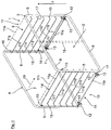
- Fig. 1 shows schematically and in perspective an exemplary embodiment of a tray rack according to the invention 1.
- This tray rack 1 has a, in traversing or insertion direction 2 (in one here not shown oven) seen front frame or rectangular frame 3 and a spaced apart in the insertion direction 2 behind the rear frame or rectangular frame 4.
- the two rectangular frames 3, 4 each have laterally opposite vertical struts 5, 6 and in the vertical axis direction opposing horizontal struts 7, 8, wherein the corner or transition areas between the vertical struts 5, 6 and the horizontal struts 7, 8 rounded here only by way of example with a defined rounding radius are formed.
- the two rectangular frames 3, 4 are preferably formed by an inner hollow hollow profile with a round or rectangular cross-section, for example, which contributes significantly to a weight-favorable structure.
- the front and rear rectangular frames 4, 5 are made of a light metal, for example aluminum or an aluminum alloy.
- the particular desired rectangular frame shape can be produced for example by bending a corresponding tubular or hollow profile, wherein the then adjacent free ends can be connected to each other, for example, a material fit.
- the two rectangular frames 3, 4 are at their transverse to the insertion direction, opposite frame sides 9, 10 respectively by means of several z seen in the vertical axis z floor-level superimposed thin or rod-like connecting struts 11 a to 11 g, each of the side parts 11 of the tray rack. 1 form, interconnected and form a rigid and stable frame composite as Hordengestell 1 from.
- each of the opposite frame sides 9, 10 forms here by way of example in each case a lowermost of the connecting struts 11 a, in the direction of insertion 2 extending wheel bearing axis, at the here only two examples, in the insertion device 2 spaced apart, and preferably in Immediately close range of the vertical struts 5, 6 arranged wheels 12 are rotatably mounted.
- the wheels 12 are also, for example, by means of a latching and / or clip connection 13, which is not shown here in detail, releasably and accurately positioned on the lowermost connecting struts 11a. So they can be easily replaced.
- each frame side 9, 10 are here preferably formed by, for example, thin or wire-like, U-shaped bracket, with its U-base 14 of the respective frame side 9, 10 away inwardly to Hordengestellmitte protrude and which are connected with their leg ends 15 respectively in the region of the associated vertical struts 5, 6 of the front and rear rectangular frame 3, 4.
- connection of the leg ends 15 takes place here for example indirectly via two vertical struts 5, 6 associated rod elements 16, 17, so that the U-shaped bracket or the connecting struts 11 b to 11 g together with the two rod elements 16, 17 each a separately manageable grid-like component or side part 11 form, which by means of the rod elements 16, 17 on the respectively associated vertical struts 5, 6 of the rectangular frame 3, 4 is easily fixable, for example, releasably fixed, for example by means of a screw, or can also be fixed permanently, for example, materially bonded (for example, adhered by means of individual welding or soldering points) or can be determined by riveting.
- the leg ends 15 but of course also directly, that is, without the rod elements 16 and 17 to the respective associated vertical struts 5, 6 of the rectangular frame 3, 4 are set, but this is not shown here
- the U-shaped bracket preferably have a cylindrical or round cross-section.
- tray rack 11 may optionally be made of a high temperature resistant plastic, for example, the connecting struts 11 b to 11 g.
- these may also be made of a steel or stainless steel material, for example a steel or stainless steel wire, which is then bent into the desired U-shape.
- the rectangular frames 3, 4 and / or the lowermost connecting strut 11a could also be made, for example, from such a high-temperature-resistant plastic. Due to the overall weight-saving construction, these rectangular frames 3, 4, in particular in the case of hollow sections, but also of a steel material, for example made of stainless steel, be made, or even, as previously stated from a light metal. Furthermore, the lowest connection strut 11a could also be made of steel, for example, although its manufacture as a hollow profile and / or of a light metal, for example of aluminum or an aluminum alloy, is preferred.
- each side frame 9 could possibly also be arranged on the z in the vertical axis direction z upper end of each side frame 9, optionally also another connecting strut 11 h, which is directly and directly connected to the vertical struts 5, 6 of the rectangular frame 3, 4 and no baking sheet Training camp.
- This optional uppermost connecting strut 11h may, for example, be designed in accordance with the lowermost connecting strut 11a and be made, for example, from light metal and / or be formed by a hollow profile.
- this optional connection strut 11 h could also be made of a high temperature resistant plastic material.
- a stop strut 18 is provided, which preferably at both the upper and at the lower horizontal strut 7, 8 of front rectangular frame 3 is attached.
- This stop strut 18 is advantageously used as a stop for the inserted into the tray rack 1 and not shown baking trays, so that they can not be pushed out of the tray rack 1 from the baking sheet insertion direction shown with a dashed arrow 19 ago.
- this stop strut 18 advantageously also serves as a pull-out aid from the oven.
- a tool engagement region and / or element for example a notch-like recess or the like, can be arranged on which tool engagement region and / or tool engagement element an extraction tool can be attached and fixed in such a way that the tray frame 1 then slides into one of the insertion direction 2 opposite extension direction can be pulled out of the oven.
- This stopper strut 18 may be made of any of the aforementioned materials.
- FIG. 2 is merely schematic and partially a modification of the in the Fig. 1 shown embodiment, in which the side parts 11 (in the Fig. 2 only one of the two opposite side parts 11 is shown) are constructed basically similar to those in the Fig. 1 , That is, that the support forming U-shaped bracket or connecting struts 11 b to 11 g here again analogous to the embodiment according to Fig. 1 with their leg ends 15 at the two, the vertical struts 5, 6 associated with rod elements 16, 17 are connected.
- the support forming U-shaped bracket or connecting struts 11 b to 11 g here again analogous to the embodiment according to Fig. 1 with their leg ends 15 at the two, the vertical struts 5, 6 associated with rod elements 16, 17 are connected.
- the support forming U-shaped bracket or connecting struts 11 b to 11 g here again analogous to the embodiment according to Fig. 1 with their leg ends 15 at the two, the vertical struts 5, 6 associated with rod elements 16, 17 are connected.
- the two rod elements 16, 17 are now not directly connected to the rectangular frame 3, 4 with their free ends, but each spaced apart from the seen in the vertical direction z, here only for example above and below the U-shaped bracket 11 b arranged to 11 g, Connecting struts 11 a and 11 h set and tethered, for example, materially bonded, to name just one example.
- the connection of such constructed, preferably separately manageable side parts 11 to the two rectangular frame 3, 4 then takes place, as in the Fig.
- connection region of the two rod elements 16, 17 on the lower connecting strut 11a is in each case a wheel 12 clipped, this connection region of the rod members 16, 17 is exploited on the connecting strut 11a to fix the headphones or displacement in the longitudinal direction of struts ,
- clip connections are provided here which, on the one hand, engage around and / or engage behind the connecting strut 11a above and below and on the other hand also the bar elements 16, 17 on the left and right.
- 17 may be provided in a central region between the two rod elements 16, 17, a third rod member 21, which can be connected with its free ends again analogous to the other two rod elements 16, 17 at the opposite connecting struts 11 a and 11 h in a manner as previously described in connection with the two rod elements 16, 17.
- this third rod element 21 can be produced and / or formed in accordance with the other two rod elements 16, 17.
- a further wheel 12 can be arranged, for example, in the manner described above, but this is not absolutely necessary.
- This third rod element 21 can bring about a further stabilization of these side parts 11 and thus of the tray rack 1, in particular in connection with relatively long-mounted side parts. It is understood that of course not only a third rod element 21 can be provided, but also further rod elements can be provided, even if this is not explicitly shown here.
Landscapes
- Engineering & Computer Science (AREA)
- Life Sciences & Earth Sciences (AREA)
- Food Science & Technology (AREA)
- Chemical & Material Sciences (AREA)
- Combustion & Propulsion (AREA)
- Mechanical Engineering (AREA)
- General Engineering & Computer Science (AREA)
- Baking, Grill, Roasting (AREA)
- Drying Of Solid Materials (AREA)
- Handcart (AREA)
Applications Claiming Priority (1)
| Application Number | Priority Date | Filing Date | Title |
|---|---|---|---|
| DE202014009645.7U DE202014009645U1 (de) | 2014-12-08 | 2014-12-08 | Hordengestell für einen, eine Backkammer aufweisenden Backofen zum Backen von insbesondere Teigwaren |
Publications (3)
| Publication Number | Publication Date |
|---|---|
| EP3031328A2 true EP3031328A2 (fr) | 2016-06-15 |
| EP3031328A3 EP3031328A3 (fr) | 2016-07-20 |
| EP3031328B1 EP3031328B1 (fr) | 2018-10-17 |
Family
ID=52389132
Family Applications (1)
| Application Number | Title | Priority Date | Filing Date |
|---|---|---|---|
| EP15003503.8A Not-in-force EP3031328B1 (fr) | 2014-12-08 | 2015-12-08 | Support pour claies pour un four de cuisson presentant une chambre de cuisson |
Country Status (2)
| Country | Link |
|---|---|
| EP (1) | EP3031328B1 (fr) |
| DE (1) | DE202014009645U1 (fr) |
Cited By (1)
| Publication number | Priority date | Publication date | Assignee | Title |
|---|---|---|---|---|
| WO2018202283A1 (fr) * | 2017-05-03 | 2018-11-08 | Arcelik Anonim Sirketi | Four multi-cuisson à efficacité fonctionnelle améliorée |
Families Citing this family (4)
| Publication number | Priority date | Publication date | Assignee | Title |
|---|---|---|---|---|
| US12372247B2 (en) | 2023-04-26 | 2025-07-29 | Sharkninja Operating Llc | Systems and methods for cooking pizza |
| US12035845B1 (en) | 2023-04-26 | 2024-07-16 | Sharkninja Operating Llc | Systems and methods for cooking pizza |
| USD1104596S1 (en) | 2023-05-31 | 2025-12-09 | Sharkninja Operating Llc | Cooking device |
| USD1101580S1 (en) | 2024-01-31 | 2025-11-11 | Sharkninja Operating Llc | Temperature probe holder |
Family Cites Families (9)
| Publication number | Priority date | Publication date | Assignee | Title |
|---|---|---|---|---|
| US4004819A (en) * | 1975-07-29 | 1977-01-25 | Metropolitan Wire Corporation | Mobile truck provided with improved removable racks for pans, trays and the like |
| GB1512646A (en) * | 1975-08-13 | 1978-06-01 | Jones D | Racks for use with baking trays |
| US4757184A (en) * | 1986-12-24 | 1988-07-12 | Swanson David L | Rack loaded, radiant heated, cantilevered deck oven and method |
| FR2682560B1 (fr) * | 1991-10-21 | 1993-12-31 | Rosinox Sa | Four de cuisson a enceinte de cuisson et chargeur amovible. |
| BE1010788A3 (nl) * | 1996-12-05 | 1999-01-05 | Sileto | Bakvorm in kunststof. |
| EP1106932B1 (fr) * | 1999-11-30 | 2004-04-28 | AEG Hausgeräte GmbH | Porte de four avec éléments de support en matière plastique |
| CA2381886A1 (fr) * | 2002-04-17 | 2003-10-17 | Patrick Murray | Supports empilables |
| DE202005008194U1 (de) * | 2005-05-25 | 2005-07-21 | Köhler GmbH | Wagen zur Aufnahme und Lagerung von mit Lebensmitteln bestückten Blechen, Rosten o.dgl. insbesondere mit Backgut bestückten Backblechen |
| FR2956949B1 (fr) * | 2010-03-04 | 2013-04-19 | Pelle Equipements | Dispositif de cuisson de produits alimentaires a base de pate et filet de cuisson. |
-
2014
- 2014-12-08 DE DE202014009645.7U patent/DE202014009645U1/de not_active Expired - Lifetime
-
2015
- 2015-12-08 EP EP15003503.8A patent/EP3031328B1/fr not_active Not-in-force
Non-Patent Citations (1)
| Title |
|---|
| None |
Cited By (1)
| Publication number | Priority date | Publication date | Assignee | Title |
|---|---|---|---|---|
| WO2018202283A1 (fr) * | 2017-05-03 | 2018-11-08 | Arcelik Anonim Sirketi | Four multi-cuisson à efficacité fonctionnelle améliorée |
Also Published As
| Publication number | Publication date |
|---|---|
| DE202014009645U1 (de) | 2015-01-07 |
| EP3031328A3 (fr) | 2016-07-20 |
| EP3031328B1 (fr) | 2018-10-17 |
Similar Documents
| Publication | Publication Date | Title |
|---|---|---|
| EP3031328B1 (fr) | Support pour claies pour un four de cuisson presentant une chambre de cuisson | |
| EP3016551B1 (fr) | Élément de tablette pour une tablette d'une étagère, en particulier d'une étagère à glissière, ainsi que cadre de tablette, tablette et étagère | |
| DE202009006858U1 (de) | Hohlprofilelement für einen Tür- oder Fensterrahmen | |
| EP2913593B1 (fr) | Dispositif destiné à maintenir un support de cuisson doté d'un élément de guidage soudé à l'avant à une barre de support et appareil de cuisson doté d'un tel dispositif | |
| EP2818077B1 (fr) | Système de fixation pour le couplage d'un châssis tubulaire avec au moins un rail télescopique | |
| DE102014110953A1 (de) | System zur Befestigung von mit Rollen versehenen Wagen in einem Fahrzeug | |
| EP3082507B1 (fr) | Tiroir de meuble et élément de paroi de tiroir pour un tiroir | |
| DE202010007825U1 (de) | Backblech für Backöfen, insbesondere für industriell betriebene Backanlagen | |
| DE102011050828A1 (de) | Abdeckung für Montagegruben | |
| DE202010003181U1 (de) | Vorrichtung zum Transportieren von Behältern | |
| DE202016101100U1 (de) | Kunststoffboden | |
| DE102010044954A1 (de) | Vorrichtung zur Aufnahme eines Gabelträgerprofils | |
| DE2225438A1 (de) | Abstuetzeinrichtung fuer rohre | |
| DE202008013187U1 (de) | Baugruppe zur Bildung eines Einkaufswagens | |
| DE202007015309U1 (de) | Tragrost und Kühl- und/oder Gefriergerät mit einem Tragrost | |
| DE10115841A1 (de) | Systemträger | |
| DE102012216608A1 (de) | Gleitschienenanordnung zur Lagerung einer Schutzabdeckung | |
| DE202009003257U1 (de) | Regalprofil mit einer Verstärkung | |
| DE102008036751A1 (de) | Profilsystem zum Zusammenfügen einer Palette | |
| DE202015100718U1 (de) | System zur Montage einer Teleskopschiene in einem Backofen | |
| DE102012104002A1 (de) | Stützrahmen für eine Transporteinrichtung | |
| DE2840090A1 (de) | Fuehrungsvorrichtung fuer schuebe | |
| DE102006005061B4 (de) | Flurförderzeug mit mindestens zwei Radarmen und Verfahren zur Montage des Flurförderzeugs | |
| DE102015114970B4 (de) | Schienensystem für einen Fahrzeugsitz und Fahrzeugsitz | |
| DE102014206591A1 (de) | Schienenauszugsvorrichtung zur Aufnahme eines Gargutträgers, Einrichtung mit einer Schienenauszugsvorrichtung sowie Gargerät |
Legal Events
| Date | Code | Title | Description |
|---|---|---|---|
| PUAI | Public reference made under article 153(3) epc to a published international application that has entered the european phase |
Free format text: ORIGINAL CODE: 0009012 |
|
| AK | Designated contracting states |
Kind code of ref document: A2 Designated state(s): AL AT BE BG CH CY CZ DE DK EE ES FI FR GB GR HR HU IE IS IT LI LT LU LV MC MK MT NL NO PL PT RO RS SE SI SK SM TR |
|
| AX | Request for extension of the european patent |
Extension state: BA ME |
|
| PUAL | Search report despatched |
Free format text: ORIGINAL CODE: 0009013 |
|
| AK | Designated contracting states |
Kind code of ref document: A3 Designated state(s): AL AT BE BG CH CY CZ DE DK EE ES FI FR GB GR HR HU IE IS IT LI LT LU LV MC MK MT NL NO PL PT RO RS SE SI SK SM TR |
|
| AX | Request for extension of the european patent |
Extension state: BA ME |
|
| RIC1 | Information provided on ipc code assigned before grant |
Ipc: A21B 1/50 20060101AFI20160610BHEP Ipc: F24C 15/16 20060101ALI20160610BHEP Ipc: A21B 3/07 20060101ALI20160610BHEP |
|
| 17P | Request for examination filed |
Effective date: 20170119 |
|
| RBV | Designated contracting states (corrected) |
Designated state(s): AL AT BE BG CH CY CZ DE DK EE ES FI FR GB GR HR HU IE IS IT LI LT LU LV MC MK MT NL NO PL PT RO RS SE SI SK SM TR |
|
| 17Q | First examination report despatched |
Effective date: 20170619 |
|
| GRAP | Despatch of communication of intention to grant a patent |
Free format text: ORIGINAL CODE: EPIDOSNIGR1 |
|
| INTG | Intention to grant announced |
Effective date: 20180507 |
|
| GRAS | Grant fee paid |
Free format text: ORIGINAL CODE: EPIDOSNIGR3 |
|
| GRAA | (expected) grant |
Free format text: ORIGINAL CODE: 0009210 |
|
| AK | Designated contracting states |
Kind code of ref document: B1 Designated state(s): AL AT BE BG CH CY CZ DE DK EE ES FI FR GB GR HR HU IE IS IT LI LT LU LV MC MK MT NL NO PL PT RO RS SE SI SK SM TR |
|
| REG | Reference to a national code |
Ref country code: GB Ref legal event code: FG4D Free format text: NOT ENGLISH |
|
| REG | Reference to a national code |
Ref country code: CH Ref legal event code: EP |
|
| REG | Reference to a national code |
Ref country code: IE Ref legal event code: FG4D Free format text: LANGUAGE OF EP DOCUMENT: GERMAN |
|
| REG | Reference to a national code |
Ref country code: DE Ref legal event code: R096 Ref document number: 502015006413 Country of ref document: DE Ref country code: AT Ref legal event code: REF Ref document number: 1052880 Country of ref document: AT Kind code of ref document: T Effective date: 20181115 |
|
| REG | Reference to a national code |
Ref country code: DE Ref legal event code: R082 Ref document number: 502015006413 Country of ref document: DE Representative=s name: NEUBAUER LIEBL BIERSCHNEIDER MASSINGER, DE Ref country code: DE Ref legal event code: R082 Ref document number: 502015006413 Country of ref document: DE Representative=s name: NEUBAUER LIEBL BIERSCHNEIDER, DE |
|
| REG | Reference to a national code |
Ref country code: CH Ref legal event code: NV Representative=s name: ABACUS PATENTANWAELTE KLOCKE SPAETH BARTH, CH |
|
| REG | Reference to a national code |
Ref country code: NL Ref legal event code: MP Effective date: 20181017 |
|
| REG | Reference to a national code |
Ref country code: LT Ref legal event code: MG4D |
|
| PG25 | Lapsed in a contracting state [announced via postgrant information from national office to epo] |
Ref country code: NL Free format text: LAPSE BECAUSE OF FAILURE TO SUBMIT A TRANSLATION OF THE DESCRIPTION OR TO PAY THE FEE WITHIN THE PRESCRIBED TIME-LIMIT Effective date: 20181017 |
|
| PG25 | Lapsed in a contracting state [announced via postgrant information from national office to epo] |
Ref country code: LT Free format text: LAPSE BECAUSE OF FAILURE TO SUBMIT A TRANSLATION OF THE DESCRIPTION OR TO PAY THE FEE WITHIN THE PRESCRIBED TIME-LIMIT Effective date: 20181017 Ref country code: NO Free format text: LAPSE BECAUSE OF FAILURE TO SUBMIT A TRANSLATION OF THE DESCRIPTION OR TO PAY THE FEE WITHIN THE PRESCRIBED TIME-LIMIT Effective date: 20190117 Ref country code: BG Free format text: LAPSE BECAUSE OF FAILURE TO SUBMIT A TRANSLATION OF THE DESCRIPTION OR TO PAY THE FEE WITHIN THE PRESCRIBED TIME-LIMIT Effective date: 20190117 Ref country code: HR Free format text: LAPSE BECAUSE OF FAILURE TO SUBMIT A TRANSLATION OF THE DESCRIPTION OR TO PAY THE FEE WITHIN THE PRESCRIBED TIME-LIMIT Effective date: 20181017 Ref country code: PL Free format text: LAPSE BECAUSE OF FAILURE TO SUBMIT A TRANSLATION OF THE DESCRIPTION OR TO PAY THE FEE WITHIN THE PRESCRIBED TIME-LIMIT Effective date: 20181017 Ref country code: FI Free format text: LAPSE BECAUSE OF FAILURE TO SUBMIT A TRANSLATION OF THE DESCRIPTION OR TO PAY THE FEE WITHIN THE PRESCRIBED TIME-LIMIT Effective date: 20181017 Ref country code: LV Free format text: LAPSE BECAUSE OF FAILURE TO SUBMIT A TRANSLATION OF THE DESCRIPTION OR TO PAY THE FEE WITHIN THE PRESCRIBED TIME-LIMIT Effective date: 20181017 Ref country code: ES Free format text: LAPSE BECAUSE OF FAILURE TO SUBMIT A TRANSLATION OF THE DESCRIPTION OR TO PAY THE FEE WITHIN THE PRESCRIBED TIME-LIMIT Effective date: 20181017 Ref country code: IS Free format text: LAPSE BECAUSE OF FAILURE TO SUBMIT A TRANSLATION OF THE DESCRIPTION OR TO PAY THE FEE WITHIN THE PRESCRIBED TIME-LIMIT Effective date: 20190217 |
|
| PGFP | Annual fee paid to national office [announced via postgrant information from national office to epo] |
Ref country code: CH Payment date: 20190318 Year of fee payment: 4 |
|
| PG25 | Lapsed in a contracting state [announced via postgrant information from national office to epo] |
Ref country code: GR Free format text: LAPSE BECAUSE OF FAILURE TO SUBMIT A TRANSLATION OF THE DESCRIPTION OR TO PAY THE FEE WITHIN THE PRESCRIBED TIME-LIMIT Effective date: 20190118 Ref country code: PT Free format text: LAPSE BECAUSE OF FAILURE TO SUBMIT A TRANSLATION OF THE DESCRIPTION OR TO PAY THE FEE WITHIN THE PRESCRIBED TIME-LIMIT Effective date: 20190217 Ref country code: RS Free format text: LAPSE BECAUSE OF FAILURE TO SUBMIT A TRANSLATION OF THE DESCRIPTION OR TO PAY THE FEE WITHIN THE PRESCRIBED TIME-LIMIT Effective date: 20181017 Ref country code: SE Free format text: LAPSE BECAUSE OF FAILURE TO SUBMIT A TRANSLATION OF THE DESCRIPTION OR TO PAY THE FEE WITHIN THE PRESCRIBED TIME-LIMIT Effective date: 20181017 Ref country code: AL Free format text: LAPSE BECAUSE OF FAILURE TO SUBMIT A TRANSLATION OF THE DESCRIPTION OR TO PAY THE FEE WITHIN THE PRESCRIBED TIME-LIMIT Effective date: 20181017 |
|
| PGFP | Annual fee paid to national office [announced via postgrant information from national office to epo] |
Ref country code: BE Payment date: 20181231 Year of fee payment: 4 |
|
| REG | Reference to a national code |
Ref country code: DE Ref legal event code: R097 Ref document number: 502015006413 Country of ref document: DE |
|
| PG25 | Lapsed in a contracting state [announced via postgrant information from national office to epo] |
Ref country code: DK Free format text: LAPSE BECAUSE OF FAILURE TO SUBMIT A TRANSLATION OF THE DESCRIPTION OR TO PAY THE FEE WITHIN THE PRESCRIBED TIME-LIMIT Effective date: 20181017 Ref country code: CZ Free format text: LAPSE BECAUSE OF FAILURE TO SUBMIT A TRANSLATION OF THE DESCRIPTION OR TO PAY THE FEE WITHIN THE PRESCRIBED TIME-LIMIT Effective date: 20181017 Ref country code: IT Free format text: LAPSE BECAUSE OF FAILURE TO SUBMIT A TRANSLATION OF THE DESCRIPTION OR TO PAY THE FEE WITHIN THE PRESCRIBED TIME-LIMIT Effective date: 20181017 |
|
| PLBE | No opposition filed within time limit |
Free format text: ORIGINAL CODE: 0009261 |
|
| STAA | Information on the status of an ep patent application or granted ep patent |
Free format text: STATUS: NO OPPOSITION FILED WITHIN TIME LIMIT |
|
| PG25 | Lapsed in a contracting state [announced via postgrant information from national office to epo] |
Ref country code: LU Free format text: LAPSE BECAUSE OF NON-PAYMENT OF DUE FEES Effective date: 20181208 Ref country code: MC Free format text: LAPSE BECAUSE OF FAILURE TO SUBMIT A TRANSLATION OF THE DESCRIPTION OR TO PAY THE FEE WITHIN THE PRESCRIBED TIME-LIMIT Effective date: 20181017 Ref country code: SK Free format text: LAPSE BECAUSE OF FAILURE TO SUBMIT A TRANSLATION OF THE DESCRIPTION OR TO PAY THE FEE WITHIN THE PRESCRIBED TIME-LIMIT Effective date: 20181017 Ref country code: SM Free format text: LAPSE BECAUSE OF FAILURE TO SUBMIT A TRANSLATION OF THE DESCRIPTION OR TO PAY THE FEE WITHIN THE PRESCRIBED TIME-LIMIT Effective date: 20181017 Ref country code: EE Free format text: LAPSE BECAUSE OF FAILURE TO SUBMIT A TRANSLATION OF THE DESCRIPTION OR TO PAY THE FEE WITHIN THE PRESCRIBED TIME-LIMIT Effective date: 20181017 Ref country code: RO Free format text: LAPSE BECAUSE OF FAILURE TO SUBMIT A TRANSLATION OF THE DESCRIPTION OR TO PAY THE FEE WITHIN THE PRESCRIBED TIME-LIMIT Effective date: 20181017 |
|
| REG | Reference to a national code |
Ref country code: IE Ref legal event code: MM4A |
|
| 26N | No opposition filed |
Effective date: 20190718 |
|
| PG25 | Lapsed in a contracting state [announced via postgrant information from national office to epo] |
Ref country code: SI Free format text: LAPSE BECAUSE OF FAILURE TO SUBMIT A TRANSLATION OF THE DESCRIPTION OR TO PAY THE FEE WITHIN THE PRESCRIBED TIME-LIMIT Effective date: 20181017 Ref country code: IE Free format text: LAPSE BECAUSE OF NON-PAYMENT OF DUE FEES Effective date: 20181208 |
|
| PG25 | Lapsed in a contracting state [announced via postgrant information from national office to epo] |
Ref country code: MT Free format text: LAPSE BECAUSE OF FAILURE TO SUBMIT A TRANSLATION OF THE DESCRIPTION OR TO PAY THE FEE WITHIN THE PRESCRIBED TIME-LIMIT Effective date: 20181017 |
|
| PG25 | Lapsed in a contracting state [announced via postgrant information from national office to epo] |
Ref country code: TR Free format text: LAPSE BECAUSE OF FAILURE TO SUBMIT A TRANSLATION OF THE DESCRIPTION OR TO PAY THE FEE WITHIN THE PRESCRIBED TIME-LIMIT Effective date: 20181017 |
|
| PG25 | Lapsed in a contracting state [announced via postgrant information from national office to epo] |
Ref country code: CY Free format text: LAPSE BECAUSE OF FAILURE TO SUBMIT A TRANSLATION OF THE DESCRIPTION OR TO PAY THE FEE WITHIN THE PRESCRIBED TIME-LIMIT Effective date: 20181017 Ref country code: MK Free format text: LAPSE BECAUSE OF NON-PAYMENT OF DUE FEES Effective date: 20181017 Ref country code: HU Free format text: LAPSE BECAUSE OF FAILURE TO SUBMIT A TRANSLATION OF THE DESCRIPTION OR TO PAY THE FEE WITHIN THE PRESCRIBED TIME-LIMIT; INVALID AB INITIO Effective date: 20151208 |
|
| REG | Reference to a national code |
Ref country code: CH Ref legal event code: PL |
|
| REG | Reference to a national code |
Ref country code: BE Ref legal event code: MM Effective date: 20191231 |
|
| PG25 | Lapsed in a contracting state [announced via postgrant information from national office to epo] |
Ref country code: BE Free format text: LAPSE BECAUSE OF NON-PAYMENT OF DUE FEES Effective date: 20191231 Ref country code: LI Free format text: LAPSE BECAUSE OF NON-PAYMENT OF DUE FEES Effective date: 20191231 Ref country code: CH Free format text: LAPSE BECAUSE OF NON-PAYMENT OF DUE FEES Effective date: 20191231 |
|
| PGFP | Annual fee paid to national office [announced via postgrant information from national office to epo] |
Ref country code: FR Payment date: 20201230 Year of fee payment: 6 Ref country code: GB Payment date: 20201217 Year of fee payment: 6 Ref country code: AT Payment date: 20201209 Year of fee payment: 6 |
|
| REG | Reference to a national code |
Ref country code: AT Ref legal event code: MM01 Ref document number: 1052880 Country of ref document: AT Kind code of ref document: T Effective date: 20211208 |
|
| GBPC | Gb: european patent ceased through non-payment of renewal fee |
Effective date: 20211208 |
|
| PG25 | Lapsed in a contracting state [announced via postgrant information from national office to epo] |
Ref country code: GB Free format text: LAPSE BECAUSE OF NON-PAYMENT OF DUE FEES Effective date: 20211208 Ref country code: AT Free format text: LAPSE BECAUSE OF NON-PAYMENT OF DUE FEES Effective date: 20211208 |
|
| PG25 | Lapsed in a contracting state [announced via postgrant information from national office to epo] |
Ref country code: FR Free format text: LAPSE BECAUSE OF NON-PAYMENT OF DUE FEES Effective date: 20211231 |
|
| PGFP | Annual fee paid to national office [announced via postgrant information from national office to epo] |
Ref country code: DE Payment date: 20240129 Year of fee payment: 9 |
|
| REG | Reference to a national code |
Ref country code: DE Ref legal event code: R119 Ref document number: 502015006413 Country of ref document: DE |
|
| PG25 | Lapsed in a contracting state [announced via postgrant information from national office to epo] |
Ref country code: DE Free format text: LAPSE BECAUSE OF NON-PAYMENT OF DUE FEES Effective date: 20250701 |