EP3032008A1 - Système de verrouillage à actuation thermique pour panneaux - Google Patents
Système de verrouillage à actuation thermique pour panneaux Download PDFInfo
- Publication number
- EP3032008A1 EP3032008A1 EP15199602.2A EP15199602A EP3032008A1 EP 3032008 A1 EP3032008 A1 EP 3032008A1 EP 15199602 A EP15199602 A EP 15199602A EP 3032008 A1 EP3032008 A1 EP 3032008A1
- Authority
- EP
- European Patent Office
- Prior art keywords
- locking system
- pin
- panel
- shaft
- activator
- Prior art date
- Legal status (The legal status is an assumption and is not a legal conclusion. Google has not performed a legal analysis and makes no representation as to the accuracy of the status listed.)
- Granted
Links
Images

Classifications
-
- E—FIXED CONSTRUCTIONS
- E05—LOCKS; KEYS; WINDOW OR DOOR FITTINGS; SAFES
- E05B—LOCKS; ACCESSORIES THEREFOR; HANDCUFFS
- E05B65/00—Locks or fastenings for special use
- E05B65/10—Locks or fastenings for special use for panic or emergency doors
- E05B65/104—Locks or fastenings for special use for panic or emergency doors actuated in response to heat, e.g. with fusible element, bimetal, memory shape or swelling material
Definitions
- This invention relates on the one hand to a locking system for locking a panel in the event of fire in order to close off an opening between two spaces, comprising
- the panel is in particular a glass panel.
- the panel can be a pivotable door panel of, for example, a swing door, but can also be a fixed panel.
- This invention also relates to a panel comprising such a locking system.
- this invention also relates to a method of producing such a locking system.
- Locking systems of this type are used in fire-resistant panels.
- These panels can be fixed panels or hinged panels, such as, for example, door panels. In the event of fire, these panels are provided to form, for a certain time, a fire barrier between the two spaces in order thus to avoid fire penetration for a certain time.
- the panels can be, for example, glass panels, made of fireproof/fire-resistant glass.
- These fireproof/fire-resistant glass panels can comprise a plurality of glass panes between which fire-resistant material, such as, for example, a fire-resistant gel, is placed.
- the glass panes can be made of floatglass, pressed glass, toughened glass, thermally tempered glass, laminated glass, layered glass, etc.
- a panel Partly as a result of the high temperatures in a fire, such a panel does however have a tendency to deform, with the result that the opening between two spaces, which normally is closed off by the panel, is no longer closed off as effectively. Fire penetration from one space to the other space will hence occur more rapidly.
- a locking system which locks the panel in the event of fire in order to prevent the deformation of the panel is hence provided. If the panel is a pivotable door panel, then the locking system will also ensure that the door panel will not pivot during the fire, so that the opening is always closed off by the panel.
- Examples of existing locking systems are represented in GB 2321492 , EP 2612975 and GB 2237835 . These locking systems all comprise a shaft, in which a pin is guidingly arranged, and wherein the pin is at least partially ejectable from the shaft in the presence of heat.
- the pin is ejectable with the aid of a spring and the ejection is prevented by a plastics piece which melts under the influence of heat. During a fire, this plastics piece will melt, with the result that the spring can eject the pin.
- EP 262975 the pin is ejectable in the event of fire with the aid of material which swells under the influence of heat.
- the pin is ejectable with the aid of a spring and the ejection is prevented by wax. In the event of fire, this wax will melt, with the result that the spring can eject the pin.
- This object is achieved by providing a locking system for locking a panel in the event of fire in order to close off an opening between two spaces, comprising
- fusible link melts very quickly. As soon as during a fire, at the height of the locking system located on or in the vicinity of the panel, the temperature exceeds the melting temperature of the fusible link, the fusible link will instantly melt. Once the fusible link has melted, the blocking element no longer prevents the ejection of the pin, with the result that the pin is ejected by the activator. Since the melting of the fusible link takes little time, the locking system will also quickly lock the panel in the event of fire. The panel hence does not have time to deform and/or shift, with the result that, during a fire, the opening is always closed off by the panel and fire penetration from one space to the other space is delayed.
- the pin is ejected into a cavity which is arranged opposite the locking system.
- the pin then preferably extends partly into the shaft of the locking system and partly into the said cavity.
- the locking system comprises a heat transfer element for connecting the two spaces, wherein the blocking element is in contact with the heat transfer element.
- the heat transfer element transfers the heat between the two said spaces, so that the blocking element warms up sufficiently during a fire, even if this blocking element is arranged between the two spaces or in the space in which no fire is burning.
- the fusible link will here always melt in time.
- the heat transfer element will ensure that the temperature of the blocking element will always rise sufficiently in the event of fire, even if the fire occurs in a said space and the blocking element extends substantially into the other said space.
- the blocking element comprises no fusible link, but other elements or components which melt, deform, shift, etc. in the presence of heat, so that the activator can drive the pin at least partially out of the shaft, the said additional problem is solved.
- the heat transfer element preferably comprises a metal plate.
- Metal is a good heat conductor and is thus well capable of transferring heat to the blocking element.
- a plate can be thinly constructed, so that not too much heat is conducted from one space to the other space and thus heat is transmitted above all to the blocking element.
- the metal plate can be of either curved or uncurved construction.
- the metal plate is a perforated metal plate.
- the metal plate here ensures the connection between the two spaces.
- the connection is normally realized by virtue of the fact that the metal plate extends between the frame of the opening and the panel and is thus in contact with the two spaces. It is not desirable for the panel or the environment, at the height of this panel, to heat up a lot. It is simply the aim that the blocking element acquires the necessary heat.
- the metal plate is provided with perforations or openings, above all at the height of the panel.
- the activator is preferably provided to drive the pin through an ejection opening of the shaft, wherein the blocking element at least partially closes off this ejection opening. In order to be able to lock the panel, the pin is then driven at least partially through this ejection opening.
- the fusible link melts, a hole must be formed in the blocking element, through which the pin can be ejected. Hence the hole must at least correspond with the dimensions of the pin. If less than the full ejection opening is freed by the melting of the fusible link, it can be provided, for example, that the portion around the formed hole detains the pin after this has been in large part ejected.
- the pin can be provided at the bottom, for example, with a widened foot, in which case this widened foot is too wide to move through the formed hole, with the result that the pin is detained.
- the shaft is accommodated in a housing, and the blocking element is provided to be connected to the housing.
- the blocking element can then here be provided as a separate component.
- the housing and the blocking element can hence initially be produced separately, after which they are then subsequently fastened to each other. The production of the locking system can hereby proceed smoothly and rapidly.
- the activator comprises a compressible spring.
- the blocking element no longer prevents the activator from at least partially ejecting the pin, the pin will be very rapidly ejected with the aid of the spring.
- the panel is then instantly locked as soon as the blocking element no longer obstructs the activator, with the result that the chance that the panel has time to deform and/or shift is very small.
- the blocking element comprises a cavity, which connects to the shaft and in which the fusible link is at least partially arranged, wherein this cavity comprises a locking element, extending at a distance from the shaft, for locking the fusible link according to the direction with which the pin is ejectable from the shaft by the activator.
- the activator aims to drive the pin at least partially out of the shaft.
- the blocking element prevents this when there is no fire.
- the fusible link melts the activator will eject the pin according to a specific direction. This direction can be denoted by the term direction of ejection.
- the locking element prevents the fusible link in its solid state from shifting in the cavity according to the direction of ejection.
- this locking element is further preferably a locking rim.
- this said cavity can consist, for example, of at least two parts, i.e., viewed according to the direction of ejection, a first part having a larger cross section and a second part having a smaller cross section, such that a locking rim is formed there between the two parts.
- the locking system comprises
- the second blocking element further preferably comprises fusible link, so that in the event of fire this fusible link melts and thus the second activator is no longer prevented from at least partially ejecting the second pin.
- the first said pin is provided to extend into one said space next to the panel
- the second said pen is provided to extend into the other said space next to the panel.
- the locking system can then here prevent the panel from bending in the direction of one of the two spaces.
- This locking system is also very suitable for a panel which is a pivotable door panel of a swing door. With the aid of this locking system, the door panel is then prevented from being able to pivot.
- the locking system here therefore comprises a heat transfer element which is in contact with both blocking elements, so that heat is also transferred to the blocking element which is not located in the space in which fire is burning. In this way, the pins will be ejected virtually at the same moment in the event of fire, with the result that the panel is immediately locked very securely.
- the locking system comprises a detaining element in order to prevent the pin from being driven fully out of the shaft by the activator.
- the pin then remains partially in the shaft in the event of fire. Movement of the panel, when the pin has been partially ejected from the shaft, is therefore partially absorbed by the shaft.
- a detaining element can be a frame or a protruding pin.
- the pin is then here preferably itself provided with a protruding portion which then butts against the frame or the pin during the ejection of the pin, with the result that the pin is then no longer further ejected.
- the melt temperature of the fusible link is preferably between 50 °C and 70 °C, more preferably between 55 °C and 65 °C.
- the fusible link is preferably a composition of bismuth and/or cadmium and/or lead and/or tin and/or indium. It preferably comprises no cadmium and lead, since these substances are harmful to health.
- the fusible link can be, for example, 'Field's metal'. This fusible link comprises the following percentages by weight: +/- 32.5% bismuth, +/- 51% indium and +/-16.5% tin.
- This invention also relates to a panel for closing off an opening between two spaces, comprising a locking system in order to lock the panel in the event of fire, wherein the locking system is a locking system as described above.
- the locking system which is described above is thus preferably provided to be mounted on a panel.
- the panel is, for example, a pivotable door panel of a swing door.
- no adaptations have here to be made at the height of the frame of the opening closed off by the panel.
- the above-described advantages of the locking system are also applicable to this panel.
- the locking system could also however be fastened to the frame of the opening closed off by the panel.
- the panel can be, for example, a fixed panel, or can be constructed as a pivotable door leaf.
- the panel is a glass panel.
- a glass panel is a panel comprising one or more glass surfaces. Between these various glass surfaces can be found other materials, such as, for example, air, fire-resistant material, such as fire-resistant gel, cladding material, etc. The glass surfaces themselves can also be coated or uncoated. Glass panels can, inter alia, be of translucent, matt, sun-shielding or reflective construction. More specifically, the door panel can be made of fire-resistant glass. Such fire-resistant glass comprises one or more glass panes, between which fire-resistant material is placed. In this case, depending on the fire resistance requirements, the glass panes can be made of floatglass, pressed glass, toughened glass, thermally tempered glass, laminated glass, layered glass, etc.
- the aforesaid object is also achieved by providing a method for producing a locking system, wherein the locking system is a locking system as described above, and wherein the blocking element comprises a cavity into which the fusible link is fitted in its molten state.
- this cavity comprises a locking element, extending at a distance from the shaft, for locking the fusible link according to the direction of ejection of the pin, then this is a good method of getting the fusible link in the cavity.
- the fusible link is fitted in a solid state at the top of the cavity in order subsequently to be exposed to a heat source, so that the fusible link melts and thus at least partially fills the cavity.
- a piece of fusible link for example, can be fitted into the cavity and this then melted so that it assumes the correct form in the cavity.
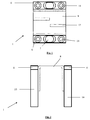
- the locking system (1) is used to lock a panel (2) in the event of fire.
- the panel (2) is here a glazed door panel (2) which is pivotably connected to a wall (12).
- the door panel (2) is lockable in its closed position, as depicted in Figure 4 , i.e. the position in which the door panel (2) closes off an opening between two spaces.
- the locking system (1) comprises a first housing (10) and a second housing (10), as can be seen in Figures 2 and 4 .
- each housing (10) comprises a shaft (3) in which a pin (4) is arranged such that it is guidingly displaceable.
- the locking system (1) further comprises two blocking elements (6), which are each connected to a said housing (10) and close off an ejection opening (9) of the shaft (3).
- the blocking elements (6) arc for this purpose provided with fusible link (7).
- the connection between a said blocking element (6) and a said housing (10) is made with the aid of screws.
- the blocking elements (6) and the housings (10) are for this purpose provided with bores (14) comprising a screw thread in which a screw can engage.
- a helical spring (5) is arranged in the shaft (3) opposite the ejection opening (9), for driving the pin (4) partially out of the shaft (3).
- the fusible link (7) is unmelted, thus when no fire has yet occurred in one of the said spaces, the helical spring (5) is compressed and presses the pin (4) against the fusible link (7).
- the fusible link (7) is for this purpose located in a cavity (11) of the blocking element (6), which cavity extends at the height of the ejection opening (9). During a fire, the temperature at the height of the fusible link (7) will increase, with the result that the fusible link (7) melts and the helical spring (5) can drive the pin (4) partly out of the shaft (3).
- This cavity (11) of the blocking element (6) is arranged opposite the shaft and the fusible link (7) extends into this cavity (11).
- this cavity (11) consists of two parts, which, viewed according to the longitudinal direction of the shaft (3), have two different cross sections, wherein a first part, which is located close to the shaft (3), has a larger cross section. Between these two parts there is hence a locking rim (17).
- the fusible link (7) is arranged in both parts and that part of the fusible link (7) which is arranged in the first part extends between the stop rim (17) and the pin (4).
- the fusible link (7) here securely detains the pin (4).
- the locking system (1) is provided to be connected to the door panel (2) in such a way that one housing (10), viewed according to the transverse direction of the panel (2), extends on one side of the door panel (2), and the other housing (10) extends on the other side of the door panel (2). This is apparent in Figure 4 .
- the locking system (1) comprises a heat transfer element (8).
- This heat transfer element (8) is a bent plate, having a central portion and two upright portions, whereof the cross section is U-shaped. Each upright portion of the heat transfer element (8) is connected to a said housing (10) and to a said blocking element (6) and extends on a side of the door panel (2). With the aid of this heat transfer element (8), heat is exchangeable between the said spaces. Thus the heat present in one said space during a fire will be transmitted by the heat transfer element (8) to the blocking element (6) located in the other space. The fusible link (7) will hereby acquire the necessary heat. It is hereby ensured that both pins (4) are ejected almost simultaneously during a fire.
- the central portion of the heat transfer element (8) comprises perforation openings (13). Through these perforation openings (13), the heat is substantially exchanged between the blocking elements (6) and the heat is not conducted to other elements or components, such as, for example, the space extending around the opening.
- the wall (12) to which the door panel (2) is pivotably connected is provided with positioning elements (15) at the height of the locking system (1).
- positioning elements (15) comprise a cavity (16) in which the pin (4) from the corresponding housing (10) can engage after the ejection thereof.
- the pin (4) will then extend partly into a said positioning element (15) and partly into the shaft (3) of the housing (10), with the result that the door panel (2) is no longer pivotable relative to the wall (12) and is not deformable.
Landscapes
- Business, Economics & Management (AREA)
- Emergency Management (AREA)
- Special Wing (AREA)
Priority Applications (3)
| Application Number | Priority Date | Filing Date | Title |
|---|---|---|---|
| PL15199602T PL3032008T3 (pl) | 2014-12-11 | 2015-12-11 | Uruchamiany ciepłem układ blokujący dla panelu |
| SI201530363T SI3032008T1 (sl) | 2014-12-11 | 2015-12-11 | Toplotno aktiviran zapahnilni sistem za ploščo |
| HRP20181281TT HRP20181281T1 (hr) | 2014-12-11 | 2018-08-03 | Toplinski aktuirani sustav za zabravljivanje panela |
Applications Claiming Priority (1)
| Application Number | Priority Date | Filing Date | Title |
|---|---|---|---|
| BE2014/5115A BE1023254B1 (nl) | 2014-12-11 | 2014-12-11 | Vergrendelsysteem voor een paneel |
Publications (2)
| Publication Number | Publication Date |
|---|---|
| EP3032008A1 true EP3032008A1 (fr) | 2016-06-15 |
| EP3032008B1 EP3032008B1 (fr) | 2018-07-25 |
Family
ID=52705899
Family Applications (1)
| Application Number | Title | Priority Date | Filing Date |
|---|---|---|---|
| EP15199602.2A Active EP3032008B1 (fr) | 2014-12-11 | 2015-12-11 | Système de verrouillage à actuation thermique pour panneaux |
Country Status (6)
| Country | Link |
|---|---|
| EP (1) | EP3032008B1 (fr) |
| BE (1) | BE1023254B1 (fr) |
| DK (1) | DK3032008T3 (fr) |
| HR (1) | HRP20181281T1 (fr) |
| PL (1) | PL3032008T3 (fr) |
| SI (1) | SI3032008T1 (fr) |
Cited By (1)
| Publication number | Priority date | Publication date | Assignee | Title |
|---|---|---|---|---|
| CN109750912A (zh) * | 2019-01-09 | 2019-05-14 | 浙江齐嘉消防科技有限公司 | 一种火灾时自动解锁的防火门锁 |
Citations (11)
| Publication number | Priority date | Publication date | Assignee | Title |
|---|---|---|---|---|
| US3325941A (en) * | 1965-10-04 | 1967-06-20 | Turnbull Elevator Ltd | Fire door restraining devices |
| US4161804A (en) * | 1977-12-21 | 1979-07-24 | Rixson-Firemark, Inc. | Heat-actuated door latch |
| NL8002408A (nl) * | 1980-04-24 | 1981-11-16 | Polynorm Nv | Grendelinrichting. |
| DE3315351A1 (de) * | 1983-04-28 | 1984-10-31 | Leininger-Brandschutzelemente GmbH, 5000 Köln | Selbsttaetig ausloesendes verriegelungselement fuer eine brandschutztuer |
| EP0156044A2 (fr) * | 1984-03-27 | 1985-10-02 | D.R.I.M. Limited | Porte coupe-feu |
| EP0262975A2 (fr) | 1986-10-02 | 1988-04-06 | General Electric Company | Encres pour conducteur cuivré à film épais |
| GB2237835A (en) | 1989-10-31 | 1991-05-15 | Manchester City Council | A security door. |
| GB2321492A (en) | 1997-01-22 | 1998-07-29 | Anthony Elworthy | Thermally actuated bolt |
| KR20100110424A (ko) * | 2009-04-03 | 2010-10-13 | 주식회사 세종 | 방화문 자동 화재 안전핀 |
| US20110204658A1 (en) * | 2010-02-23 | 2011-08-25 | Hsi-Ting Lin | Fire Bolt Assembly for Door |
| EP2612975A2 (fr) | 2012-01-06 | 2013-07-10 | Remigijus Guobys | Goupille de verrouillage de porte thermique |
-
2014
- 2014-12-11 BE BE2014/5115A patent/BE1023254B1/nl active IP Right Grant
-
2015
- 2015-12-11 PL PL15199602T patent/PL3032008T3/pl unknown
- 2015-12-11 DK DK15199602.2T patent/DK3032008T3/en active
- 2015-12-11 EP EP15199602.2A patent/EP3032008B1/fr active Active
- 2015-12-11 SI SI201530363T patent/SI3032008T1/sl unknown
-
2018
- 2018-08-03 HR HRP20181281TT patent/HRP20181281T1/hr unknown
Patent Citations (11)
| Publication number | Priority date | Publication date | Assignee | Title |
|---|---|---|---|---|
| US3325941A (en) * | 1965-10-04 | 1967-06-20 | Turnbull Elevator Ltd | Fire door restraining devices |
| US4161804A (en) * | 1977-12-21 | 1979-07-24 | Rixson-Firemark, Inc. | Heat-actuated door latch |
| NL8002408A (nl) * | 1980-04-24 | 1981-11-16 | Polynorm Nv | Grendelinrichting. |
| DE3315351A1 (de) * | 1983-04-28 | 1984-10-31 | Leininger-Brandschutzelemente GmbH, 5000 Köln | Selbsttaetig ausloesendes verriegelungselement fuer eine brandschutztuer |
| EP0156044A2 (fr) * | 1984-03-27 | 1985-10-02 | D.R.I.M. Limited | Porte coupe-feu |
| EP0262975A2 (fr) | 1986-10-02 | 1988-04-06 | General Electric Company | Encres pour conducteur cuivré à film épais |
| GB2237835A (en) | 1989-10-31 | 1991-05-15 | Manchester City Council | A security door. |
| GB2321492A (en) | 1997-01-22 | 1998-07-29 | Anthony Elworthy | Thermally actuated bolt |
| KR20100110424A (ko) * | 2009-04-03 | 2010-10-13 | 주식회사 세종 | 방화문 자동 화재 안전핀 |
| US20110204658A1 (en) * | 2010-02-23 | 2011-08-25 | Hsi-Ting Lin | Fire Bolt Assembly for Door |
| EP2612975A2 (fr) | 2012-01-06 | 2013-07-10 | Remigijus Guobys | Goupille de verrouillage de porte thermique |
Cited By (1)
| Publication number | Priority date | Publication date | Assignee | Title |
|---|---|---|---|---|
| CN109750912A (zh) * | 2019-01-09 | 2019-05-14 | 浙江齐嘉消防科技有限公司 | 一种火灾时自动解锁的防火门锁 |
Also Published As
| Publication number | Publication date |
|---|---|
| PL3032008T3 (pl) | 2018-12-31 |
| SI3032008T1 (sl) | 2018-10-30 |
| HRP20181281T1 (hr) | 2018-10-05 |
| BE1023254B1 (nl) | 2017-01-11 |
| BE1023254A1 (nl) | 2017-01-11 |
| DK3032008T3 (en) | 2018-08-27 |
| EP3032008B1 (fr) | 2018-07-25 |
Similar Documents
| Publication | Publication Date | Title |
|---|---|---|
| US5464259A (en) | Door latch assembly with meltable fuse mechanism | |
| JP5354756B2 (ja) | 電気式ドアロック装置 | |
| EP3535467B1 (fr) | Mécanisme de verrouillage de sécurité/d'incendie à double fonction pour dispositifs coupe-feu | |
| US8955194B2 (en) | Fire door hinge with fusible pin | |
| KR102154233B1 (ko) | 방화문용 열 변형 방지기구 | |
| JP6096462B2 (ja) | 開口部装置 | |
| SI20430A (sl) | Protipožarna stena | |
| CN111395894B (zh) | 一种锁止机构及温感门窗闭合装置 | |
| EP3032008B1 (fr) | Système de verrouillage à actuation thermique pour panneaux | |
| CN208885136U (zh) | 防火门用锁具 | |
| EP2199516B1 (fr) | Fixation pour doubles vitrifications ignifuges | |
| CN204850814U (zh) | 一种可熔断排烟、排热窗扇固定机构 | |
| JP6001307B2 (ja) | 開閉窓 | |
| CN208396531U (zh) | 弹性自动闭窗器以及安装上述闭窗器的耐火窗、防火窗 | |
| EP2372069B1 (fr) | Dormant pare-feu en bois | |
| CN213359876U (zh) | 隧道联络通道专用抗风压防火逃生安全门 | |
| CN111485806A (zh) | 一种隐藏式防火窗 | |
| CN113482480B (zh) | 一种温控锁止机构及温感门窗闭合装置 | |
| CN211691988U (zh) | 一种温控闭窗装置及温控闭合窗 | |
| JP6449034B2 (ja) | 樹脂サッシ | |
| CN212428389U (zh) | 一种锁止机构及温感门窗闭合装置 | |
| WO2017174578A1 (fr) | Vitrage doté de la jointure | |
| WO2018015066A1 (fr) | Vitrage coupe-feu transparent ayant des propriétés de résistance à l'effraction et anti-panique | |
| DE102006057288A1 (de) | Notein- und Notausstiegsfenster | |
| JP6600238B2 (ja) | 横軸回転窓 |
Legal Events
| Date | Code | Title | Description |
|---|---|---|---|
| PUAI | Public reference made under article 153(3) epc to a published international application that has entered the european phase |
Free format text: ORIGINAL CODE: 0009012 |
|
| AK | Designated contracting states |
Kind code of ref document: A1 Designated state(s): AL AT BE BG CH CY CZ DE DK EE ES FI FR GB GR HR HU IE IS IT LI LT LU LV MC MK MT NL NO PL PT RO RS SE SI SK SM TR |
|
| AX | Request for extension of the european patent |
Extension state: BA ME |
|
| 17P | Request for examination filed |
Effective date: 20161205 |
|
| RBV | Designated contracting states (corrected) |
Designated state(s): AL AT BE BG CH CY CZ DE DK EE ES FI FR GB GR HR HU IE IS IT LI LT LU LV MC MK MT NL NO PL PT RO RS SE SI SK SM TR |
|
| 17Q | First examination report despatched |
Effective date: 20170517 |
|
| GRAP | Despatch of communication of intention to grant a patent |
Free format text: ORIGINAL CODE: EPIDOSNIGR1 |
|
| INTG | Intention to grant announced |
Effective date: 20180123 |
|
| GRAS | Grant fee paid |
Free format text: ORIGINAL CODE: EPIDOSNIGR3 |
|
| GRAA | (expected) grant |
Free format text: ORIGINAL CODE: 0009210 |
|
| AK | Designated contracting states |
Kind code of ref document: B1 Designated state(s): AL AT BE BG CH CY CZ DE DK EE ES FI FR GB GR HR HU IE IS IT LI LT LU LV MC MK MT NL NO PL PT RO RS SE SI SK SM TR |
|
| RAP1 | Party data changed (applicant data changed or rights of an application transferred) |
Owner name: SAINT-GOBAIN GLASS FRANCE S.A. |
|
| REG | Reference to a national code |
Ref country code: GB Ref legal event code: FG4D |
|
| REG | Reference to a national code |
Ref country code: CH Ref legal event code: EP |
|
| REG | Reference to a national code |
Ref country code: HR Ref legal event code: TUEP Ref document number: P20181281 Country of ref document: HR |
|
| REG | Reference to a national code |
Ref country code: CH Ref legal event code: NV Representative=s name: RENTSCH PARTNER AG, CH Ref country code: AT Ref legal event code: REF Ref document number: 1021936 Country of ref document: AT Kind code of ref document: T Effective date: 20180815 |
|
| REG | Reference to a national code |
Ref country code: IE Ref legal event code: FG4D |
|
| REG | Reference to a national code |
Ref country code: DE Ref legal event code: R096 Ref document number: 602015013936 Country of ref document: DE |
|
| REG | Reference to a national code |
Ref country code: DK Ref legal event code: T3 Effective date: 20180820 |
|
| REG | Reference to a national code |
Ref country code: NL Ref legal event code: FP |
|
| REG | Reference to a national code |
Ref country code: SE Ref legal event code: TRGR |
|
| REG | Reference to a national code |
Ref country code: HR Ref legal event code: T1PR Ref document number: P20181281 Country of ref document: HR |
|
| REG | Reference to a national code |
Ref country code: HR Ref legal event code: ODRP Ref document number: P20181281 Country of ref document: HR Payment date: 20181112 Year of fee payment: 4 |
|
| REG | Reference to a national code |
Ref country code: LT Ref legal event code: MG4D |
|
| PG25 | Lapsed in a contracting state [announced via postgrant information from national office to epo] |
Ref country code: FI Free format text: LAPSE BECAUSE OF FAILURE TO SUBMIT A TRANSLATION OF THE DESCRIPTION OR TO PAY THE FEE WITHIN THE PRESCRIBED TIME-LIMIT Effective date: 20180725 Ref country code: NO Free format text: LAPSE BECAUSE OF FAILURE TO SUBMIT A TRANSLATION OF THE DESCRIPTION OR TO PAY THE FEE WITHIN THE PRESCRIBED TIME-LIMIT Effective date: 20181025 Ref country code: IS Free format text: LAPSE BECAUSE OF FAILURE TO SUBMIT A TRANSLATION OF THE DESCRIPTION OR TO PAY THE FEE WITHIN THE PRESCRIBED TIME-LIMIT Effective date: 20181125 Ref country code: GR Free format text: LAPSE BECAUSE OF FAILURE TO SUBMIT A TRANSLATION OF THE DESCRIPTION OR TO PAY THE FEE WITHIN THE PRESCRIBED TIME-LIMIT Effective date: 20181026 Ref country code: RS Free format text: LAPSE BECAUSE OF FAILURE TO SUBMIT A TRANSLATION OF THE DESCRIPTION OR TO PAY THE FEE WITHIN THE PRESCRIBED TIME-LIMIT Effective date: 20180725 Ref country code: BG Free format text: LAPSE BECAUSE OF FAILURE TO SUBMIT A TRANSLATION OF THE DESCRIPTION OR TO PAY THE FEE WITHIN THE PRESCRIBED TIME-LIMIT Effective date: 20181025 Ref country code: LT Free format text: LAPSE BECAUSE OF FAILURE TO SUBMIT A TRANSLATION OF THE DESCRIPTION OR TO PAY THE FEE WITHIN THE PRESCRIBED TIME-LIMIT Effective date: 20180725 |
|
| REG | Reference to a national code |
Ref country code: SK Ref legal event code: T3 Ref document number: E 28726 Country of ref document: SK |
|
| PG25 | Lapsed in a contracting state [announced via postgrant information from national office to epo] |
Ref country code: AL Free format text: LAPSE BECAUSE OF FAILURE TO SUBMIT A TRANSLATION OF THE DESCRIPTION OR TO PAY THE FEE WITHIN THE PRESCRIBED TIME-LIMIT Effective date: 20180725 Ref country code: LV Free format text: LAPSE BECAUSE OF FAILURE TO SUBMIT A TRANSLATION OF THE DESCRIPTION OR TO PAY THE FEE WITHIN THE PRESCRIBED TIME-LIMIT Effective date: 20180725 |
|
| REG | Reference to a national code |
Ref country code: DE Ref legal event code: R097 Ref document number: 602015013936 Country of ref document: DE |
|
| PG25 | Lapsed in a contracting state [announced via postgrant information from national office to epo] |
Ref country code: ES Free format text: LAPSE BECAUSE OF FAILURE TO SUBMIT A TRANSLATION OF THE DESCRIPTION OR TO PAY THE FEE WITHIN THE PRESCRIBED TIME-LIMIT Effective date: 20180725 Ref country code: RO Free format text: LAPSE BECAUSE OF FAILURE TO SUBMIT A TRANSLATION OF THE DESCRIPTION OR TO PAY THE FEE WITHIN THE PRESCRIBED TIME-LIMIT Effective date: 20180725 Ref country code: EE Free format text: LAPSE BECAUSE OF FAILURE TO SUBMIT A TRANSLATION OF THE DESCRIPTION OR TO PAY THE FEE WITHIN THE PRESCRIBED TIME-LIMIT Effective date: 20180725 |
|
| PG25 | Lapsed in a contracting state [announced via postgrant information from national office to epo] |
Ref country code: SM Free format text: LAPSE BECAUSE OF FAILURE TO SUBMIT A TRANSLATION OF THE DESCRIPTION OR TO PAY THE FEE WITHIN THE PRESCRIBED TIME-LIMIT Effective date: 20180725 |
|
| PLBE | No opposition filed within time limit |
Free format text: ORIGINAL CODE: 0009261 |
|
| STAA | Information on the status of an ep patent application or granted ep patent |
Free format text: STATUS: NO OPPOSITION FILED WITHIN TIME LIMIT |
|
| REG | Reference to a national code |
Ref country code: AT Ref legal event code: UEP Ref document number: 1021936 Country of ref document: AT Kind code of ref document: T Effective date: 20180725 |
|
| 26N | No opposition filed |
Effective date: 20190426 |
|
| PG25 | Lapsed in a contracting state [announced via postgrant information from national office to epo] |
Ref country code: LU Free format text: LAPSE BECAUSE OF NON-PAYMENT OF DUE FEES Effective date: 20181211 Ref country code: MC Free format text: LAPSE BECAUSE OF FAILURE TO SUBMIT A TRANSLATION OF THE DESCRIPTION OR TO PAY THE FEE WITHIN THE PRESCRIBED TIME-LIMIT Effective date: 20180725 |
|
| REG | Reference to a national code |
Ref country code: HR Ref legal event code: ODRP Ref document number: P20181281 Country of ref document: HR Payment date: 20191114 Year of fee payment: 5 |
|
| PG25 | Lapsed in a contracting state [announced via postgrant information from national office to epo] |
Ref country code: MT Free format text: LAPSE BECAUSE OF NON-PAYMENT OF DUE FEES Effective date: 20181211 |
|
| PGFP | Annual fee paid to national office [announced via postgrant information from national office to epo] |
Ref country code: SK Payment date: 20191111 Year of fee payment: 5 Ref country code: IE Payment date: 20191209 Year of fee payment: 5 |
|
| PGFP | Annual fee paid to national office [announced via postgrant information from national office to epo] |
Ref country code: HR Payment date: 20191114 Year of fee payment: 5 Ref country code: SI Payment date: 20191119 Year of fee payment: 5 |
|
| PGFP | Annual fee paid to national office [announced via postgrant information from national office to epo] |
Ref country code: TR Payment date: 20191209 Year of fee payment: 5 |
|
| PG25 | Lapsed in a contracting state [announced via postgrant information from national office to epo] |
Ref country code: PT Free format text: LAPSE BECAUSE OF FAILURE TO SUBMIT A TRANSLATION OF THE DESCRIPTION OR TO PAY THE FEE WITHIN THE PRESCRIBED TIME-LIMIT Effective date: 20180725 |
|
| PG25 | Lapsed in a contracting state [announced via postgrant information from national office to epo] |
Ref country code: MK Free format text: LAPSE BECAUSE OF NON-PAYMENT OF DUE FEES Effective date: 20180725 Ref country code: CY Free format text: LAPSE BECAUSE OF FAILURE TO SUBMIT A TRANSLATION OF THE DESCRIPTION OR TO PAY THE FEE WITHIN THE PRESCRIBED TIME-LIMIT Effective date: 20180725 Ref country code: HU Free format text: LAPSE BECAUSE OF FAILURE TO SUBMIT A TRANSLATION OF THE DESCRIPTION OR TO PAY THE FEE WITHIN THE PRESCRIBED TIME-LIMIT; INVALID AB INITIO Effective date: 20151211 |
|
| REG | Reference to a national code |
Ref country code: HR Ref legal event code: PBON Ref document number: P20181281 Country of ref document: HR Effective date: 20201211 |
|
| REG | Reference to a national code |
Ref country code: SK Ref legal event code: MM4A Ref document number: E 28726 Country of ref document: SK Effective date: 20201211 |
|
| PG25 | Lapsed in a contracting state [announced via postgrant information from national office to epo] |
Ref country code: IE Free format text: LAPSE BECAUSE OF NON-PAYMENT OF DUE FEES Effective date: 20201211 Ref country code: HR Free format text: LAPSE BECAUSE OF NON-PAYMENT OF DUE FEES Effective date: 20201211 |
|
| PG25 | Lapsed in a contracting state [announced via postgrant information from national office to epo] |
Ref country code: SK Free format text: LAPSE BECAUSE OF NON-PAYMENT OF DUE FEES Effective date: 20201211 |
|
| REG | Reference to a national code |
Ref country code: SI Ref legal event code: KO00 Effective date: 20211126 |
|
| PG25 | Lapsed in a contracting state [announced via postgrant information from national office to epo] |
Ref country code: SI Free format text: LAPSE BECAUSE OF NON-PAYMENT OF DUE FEES Effective date: 20201212 |
|
| PG25 | Lapsed in a contracting state [announced via postgrant information from national office to epo] |
Ref country code: TR Free format text: LAPSE BECAUSE OF NON-PAYMENT OF DUE FEES Effective date: 20201211 |
|
| PGFP | Annual fee paid to national office [announced via postgrant information from national office to epo] |
Ref country code: SE Payment date: 20221110 Year of fee payment: 8 |
|
| P01 | Opt-out of the competence of the unified patent court (upc) registered |
Effective date: 20230515 |
|
| REG | Reference to a national code |
Ref country code: SE Ref legal event code: EUG |
|
| PG25 | Lapsed in a contracting state [announced via postgrant information from national office to epo] |
Ref country code: SE Free format text: LAPSE BECAUSE OF NON-PAYMENT OF DUE FEES Effective date: 20231212 |
|
| REG | Reference to a national code |
Ref country code: CH Ref legal event code: U11 Free format text: ST27 STATUS EVENT CODE: U-0-0-U10-U11 (AS PROVIDED BY THE NATIONAL OFFICE) Effective date: 20260101 |
|
| PGFP | Annual fee paid to national office [announced via postgrant information from national office to epo] |
Ref country code: DE Payment date: 20251211 Year of fee payment: 11 |
|
| PGFP | Annual fee paid to national office [announced via postgrant information from national office to epo] |
Ref country code: GB Payment date: 20251219 Year of fee payment: 11 |
|
| PGFP | Annual fee paid to national office [announced via postgrant information from national office to epo] |
Ref country code: AT Payment date: 20251222 Year of fee payment: 11 |
|
| PGFP | Annual fee paid to national office [announced via postgrant information from national office to epo] |
Ref country code: IT Payment date: 20251223 Year of fee payment: 11 Ref country code: DK Payment date: 20251224 Year of fee payment: 11 |
|
| PGFP | Annual fee paid to national office [announced via postgrant information from national office to epo] |
Ref country code: NL Payment date: 20251219 Year of fee payment: 11 Ref country code: FR Payment date: 20251223 Year of fee payment: 11 |
|
| PGFP | Annual fee paid to national office [announced via postgrant information from national office to epo] |
Ref country code: BE Payment date: 20251219 Year of fee payment: 11 |
|
| PGFP | Annual fee paid to national office [announced via postgrant information from national office to epo] |
Ref country code: CZ Payment date: 20251203 Year of fee payment: 11 |
|
| PGFP | Annual fee paid to national office [announced via postgrant information from national office to epo] |
Ref country code: PL Payment date: 20251128 Year of fee payment: 11 |
|
| PGFP | Annual fee paid to national office [announced via postgrant information from national office to epo] |
Ref country code: CH Payment date: 20260101 Year of fee payment: 11 |