EP3032022A1 - Procede de montage d'un dispositif d'attelage et kit de montage - Google Patents
Procede de montage d'un dispositif d'attelage et kit de montage Download PDFInfo
- Publication number
- EP3032022A1 EP3032022A1 EP15194190.3A EP15194190A EP3032022A1 EP 3032022 A1 EP3032022 A1 EP 3032022A1 EP 15194190 A EP15194190 A EP 15194190A EP 3032022 A1 EP3032022 A1 EP 3032022A1
- Authority
- EP
- European Patent Office
- Prior art keywords
- door
- slide rail
- guide element
- front panel
- furniture front
- Prior art date
- Legal status (The legal status is an assumption and is not a legal conclusion. Google has not performed a legal analysis and makes no representation as to the accuracy of the status listed.)
- Granted
Links
Images


Classifications
-
- E—FIXED CONSTRUCTIONS
- E05—LOCKS; KEYS; WINDOW OR DOOR FITTINGS; SAFES
- E05F—DEVICES FOR MOVING WINGS INTO OPEN OR CLOSED POSITION; CHECKS FOR WINGS; WING FITTINGS NOT OTHERWISE PROVIDED FOR, CONCERNED WITH THE FUNCTIONING OF THE WING
- E05F17/00—Special devices for shifting a plurality of wings operated simultaneously
-
- E—FIXED CONSTRUCTIONS
- E05—LOCKS; KEYS; WINDOW OR DOOR FITTINGS; SAFES
- E05D—HINGES OR SUSPENSION DEVICES FOR DOORS, WINDOWS OR WINGS
- E05D11/00—Additional features or accessories of hinges
- E05D11/0009—Templates for marking the position of fittings on wings or frames
-
- E—FIXED CONSTRUCTIONS
- E05—LOCKS; KEYS; WINDOW OR DOOR FITTINGS; SAFES
- E05Y—INDEXING SCHEME ASSOCIATED WITH SUBCLASSES E05D AND E05F, RELATING TO CONSTRUCTION ELEMENTS, ELECTRIC CONTROL, POWER SUPPLY, POWER SIGNAL OR TRANSMISSION, USER INTERFACES, MOUNTING OR COUPLING, DETAILS, ACCESSORIES, AUXILIARY OPERATIONS NOT OTHERWISE PROVIDED FOR, APPLICATION THEREOF
- E05Y2900/00—Application of doors, windows, wings or fittings thereof
- E05Y2900/30—Application of doors, windows, wings or fittings thereof for domestic appliances
- E05Y2900/302—Application of doors, windows, wings or fittings thereof for domestic appliances for built-in appliances
-
- E—FIXED CONSTRUCTIONS
- E05—LOCKS; KEYS; WINDOW OR DOOR FITTINGS; SAFES
- E05Y—INDEXING SCHEME ASSOCIATED WITH SUBCLASSES E05D AND E05F, RELATING TO CONSTRUCTION ELEMENTS, ELECTRIC CONTROL, POWER SUPPLY, POWER SIGNAL OR TRANSMISSION, USER INTERFACES, MOUNTING OR COUPLING, DETAILS, ACCESSORIES, AUXILIARY OPERATIONS NOT OTHERWISE PROVIDED FOR, APPLICATION THEREOF
- E05Y2900/00—Application of doors, windows, wings or fittings thereof
- E05Y2900/30—Application of doors, windows, wings or fittings thereof for domestic appliances
- E05Y2900/31—Application of doors, windows, wings or fittings thereof for domestic appliances for refrigerators
-
- F—MECHANICAL ENGINEERING; LIGHTING; HEATING; WEAPONS; BLASTING
- F25—REFRIGERATION OR COOLING; COMBINED HEATING AND REFRIGERATION SYSTEMS; HEAT PUMP SYSTEMS; MANUFACTURE OR STORAGE OF ICE; LIQUEFACTION SOLIDIFICATION OF GASES
- F25D—REFRIGERATORS; COLD ROOMS; ICE-BOXES; COOLING OR FREEZING APPARATUS NOT OTHERWISE PROVIDED FOR
- F25D23/00—General constructional features
- F25D23/02—Doors; Covers
-
- F—MECHANICAL ENGINEERING; LIGHTING; HEATING; WEAPONS; BLASTING
- F25—REFRIGERATION OR COOLING; COMBINED HEATING AND REFRIGERATION SYSTEMS; HEAT PUMP SYSTEMS; MANUFACTURE OR STORAGE OF ICE; LIQUEFACTION SOLIDIFICATION OF GASES
- F25D—REFRIGERATORS; COLD ROOMS; ICE-BOXES; COOLING OR FREEZING APPARATUS NOT OTHERWISE PROVIDED FOR
- F25D23/00—General constructional features
- F25D23/10—Arrangements for mounting in particular locations, e.g. for built-in type, for corner type
Definitions
- the invention relates to a method for mounting a towing device, which serves to couple a door of a household appliance with a furniture front panel arranged in front of the door and to carry the door with the furniture front panel.
- a guide member of the towing device is attached to the door of the household appliance, and a slide rail of the towing device is attached to the furniture front panel.
- the guide member and the slide rail are positioned relative to each other such that the slide rail can be engaged with the guide member.
- the invention relates to a mounting kit for a towing device.
- domestic appliances which are designed as built-in appliances are installed before their operation in an appropriate housing, which is referred to as furniture tables and includes a furniture body and a furniture front panel.
- the installation process is carried out either by an end user and thus a layman or by a kitchen fitter or installer.
- the furniture front panel is held by hinges on the furniture body.
- the door of the household appliance is mounted on a housing of the household appliance via hinges. Due to the different connections of the furniture front panel and the door of the household appliance and the different axes of rotation perform the door and the furniture front panel during an opening operation and a closing operation, a horizontal relative movement. During this movement, the slide rail is engaged with the guide member. When the door is closed, the furniture front panel and the door are arranged substantially parallel.
- a household appliance in the form of a household refrigerator, in which the door of the household refrigerator is entrained by the movement of the furniture front panel is, for example, in EP 0 857 929 A1 described.
- a slide is first screwed to the furniture front panel.
- a guide is brought into abutment with the furniture front panel, one of two legs standing at right angles to one another resting against the guide on a narrow side.
- This leg of the guide is brought into abutment with the narrow side of the furniture front panel to specify a depth by which the slide is to be set back with respect to the narrow side.
- the guide is separated from the slide rail and screwed to the door of the household refrigerator. Care must be taken here that the guide rail can be threaded between two guide lugs and one outer side of the guide in order subsequently to allow the refrigeration device door to be dragged along with the furniture front panel.
- a method for attaching a furniture front panel to a door of a built-in home appliance is further in the DE 196 447 34 C1 described.
- the household appliance is delivered with built-in door control parts of Verstellbehaven and positioned in front of the adjustment fittings connecting units. At the connecting parts, the furniture front panel is attached during assembly.
- the slide rail When in the EP 0 857 929 A1 First, the slide rail must be attached to the furniture front panel, and then the one for the guide element be determined position on the door of the refrigerator. Accordingly, then screw holes must be drilled in a door panel for attaching the guide member to the door. This is more troublesome than the drilling of screw holes in the furniture front panel usually formed of a wood material.
- the introduction of screw holes in the door of the household appliance can bring about undesirable damage, in particular, when the domestic appliance is a refrigeration device, wherein the door has an insulating material or a vacuum insulation.
- Object of the present invention is to provide a method of the type mentioned above and a suitable for carrying out the method mounting kit, which or which brings an improved assembly with it.
- a guide element of the towing device is attached to the door of the household appliance.
- a sliding rail of the towing device is attached to the furniture front panel.
- the guide member and the slide rail are positioned relative to each other such that the slide rail can be engaged with the guide member.
- the guide element is fixed to the door in a first step.
- the slide is fixed to the furniture front panel.
- At least one pre-assembled on the door screw is used to set the guide element on the door.
- a pre-assembled on the door screw is used for fastening, errors in mounting can be largely minimize. It is so specifically assigned to its definition of the guide screw provided its function. A likelihood of confusion with other screws, as they can be used for example to attach the slide on the furniture front panel, therefore, does not exist. This makes it particularly easy to ensure that the screws are assigned to the component of the towing device, they are to be used for their assembly.
- the pre-assembled at the same position screw can also be used in a door stop change, and it is only the towing device a mirror image, but to install in the same way. This brings cost advantages and leads to a desirable confusion security during assembly regardless of the desired door stop.
- a cost saving can also be achieved if, due to the simple handling during installation, a kitchen installer or installer requires very little assembly time because of the clear screw assignment on the towing device.
- a head of at least one screw is preferably passed through a passage opening, which is part of a recess provided in the guide element. Subsequently, the guide element is displaced relative to the at least one screw along the recess. Then the pre-assembled screw does not need to be released from the door, which further simplifies the assembly.
- a shaft of the screw is positioned in an end region of the recess, which extends at an angle to an insertion region of the recess, wherein the insertion region comprises the passage opening for the head of the screw.
- a cover element in particular a cover element can be used, which is held by a film hinge on a base body of the guide element, which comprises the recess. In that case, it is ensured that the covering element is not lost and that it is used at the point provided for the covering element. This, too, is conducive to the ease of assembly and minimization of errors.
- the covering of the recess by means of the cover can also take place after the attachment of the slide rail on the furniture front panel.
- the slide rail prior to fixing the slide rail to the furniture front panel, is positioned relative to the guide member such that the slide rail is positioned between an upper guide groove with respect to a vertical direction of the door and a lower guide groove of the guide member is located.
- the slide can be adjusted in the altitude before the slide is finally attached to the furniture front panel.
- the adjustment of the slide rail with respect to the vertical direction of the door relative to the guide element can in particular take place when the slide rail is brought into engagement with the guide element. In that case, a height adjustment of the slide bar which is particularly close to the later mounting position of the slide rail can then be realized.
- the central alignment of the slide rail with respect to the two guide grooves can be comparatively easy even by a layman by eye.
- the slide between the upper and lower guide is centered by at least one ridge of a mounting set of the towing device, which comprises the slide, is brought into abutment with a portion of the guide member. For then only the at least one web needs to be displaced along the guide element, and the slide rail is automatically centered between the two guide grooves, that is centered.
- the assembly can be greatly simplified.
- the mounting kit has two webs, which bear in each case at the top of the upper guide groove and at an underside of the lower guide groove during insertion of the guide rail in the guide grooves.
- a leg of a stop member of a mounting kit of the towing device is brought into abutment with a narrow side of the furniture front panel.
- the slide rail is held on the stop member. Due to this configuration of the stop part, a distance of the slide rail from the narrow side of the furniture front panel is given.
- the stop member can this the Have legs, which rests against the narrow side of the furniture front panel and a second leg, which extends in the direction of the slide rail.
- the at least one, used for the centering of the slide between the guide grooves web is also held on the abutment part of the mounting kit.
- the orientation of the at least one web relative to the slide rail can be specified particularly simply. This is especially true when the web or the webs project at right angles from the stop member. In that case, it is easy to arrange for the webs to run parallel to the upper and lower edges of the slide rail.
- the slide can be securely fixed to the furniture front panel.
- the door and the furniture front panel are pivoted about respective pivot axes such that at least two screw holes provided in the slide rail are accessible to a tool. This can be done, for example, by the door in about perpendicular to the housing of the household appliance and the furniture front panel are pivoted approximately perpendicular to the body of the furniture tables.
- other pivotal positions of the door and the furniture front plate are possible in which preferably two screw holes for marking markings to be provided in the furniture front panel holes are accessible.
- the position of the slide rail on the furniture front plate can be specified particularly well. This is especially true when the two outer screw holes of a plurality of equidistantly arranged in the slide screw holes are used for attaching the slide on the furniture front panel.
- the slide can be separated from a mounting kit of the towing device. Then, namely, the slide is securely held on the furniture front panel.
- the slide rail is fastened by means of at least one screw on the furniture front panel, which has been removed from a storage device of a mounting kit of the towing device.
- a storage device for the screws it is particularly easy to ensure that only the screws arranged in the storage device are used for fastening the slide rail to the furniture front panel.
- the assignment of the screws for the slide rail to the slide which is ensured by the provision of the safekeeping, leads to a simpler installation of the household appliance or to a simpler installation of the towing device.
- screw holes provided in the slide rail are concealed by means of a cover element. This can be done in particular after screwing the slide to the furniture front panel.
- a cover element can be used, which is separated from a mounting kit of the towing device.
- locking elements may be provided in the slide rail.
- the towing device comprises a guide element.
- the guide element can be attached to the door of the household appliance.
- the towing device of the mounting kit further comprises a slide rail, which can be attached to the furniture front panel.
- the guide member and the slide rail can be positioned relative to each other such that the slide rail can be engaged with the guide member, such as when the slide rail has been separated from the mounting kit.
- the mounting kit comprises a stop member, and both the slide rail and the guide member are at least indirectly held on the stop member.
- the guide element can be attached to the door before the slide is fixed to the furniture front panel.
- the position for attaching the guide member to the door can already be preset at the factory, such as by providing screw holes in the door and in particular by the provision of pre-assembled in the door screws, which can be used for fixing the guide member to the door.
- Such a mounting kit thus allows improved mounting of the towing device.
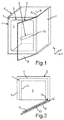
- Fig. 1 shows in perspective a household appliance 1, which is designed here as a household refrigeration appliance.
- the household refrigerating appliance can be, for example, a refrigerator or a freezer or a refrigerated combined freezer.
- the household appliance 1 has an interior 2, in which food such as food and drinks can be accommodated.
- the interior is bounded by walls of an inner container 3, wherein the inner container 3 is surrounded by an outer housing 4.
- a front-side charging opening of the inner container 3 and the outer housing 4 can be closed by a door 5.
- the door 5 is in Fig. 1 shown in the open state.
- the door 5 is at the in Fig. 1 an embodiment shown at Front side view arranged on the right side and vertically, ie in the y-direction, pivot axis A pivotally.
- the door 5 is preferably hinged to the inner container 3 and / or to the outer housing 4 struck.
- the household appliance 1 is installed in a furniture recess 6 which comprises a furniture carcass 7 and a furniture front panel 8 rotatably arranged on the furniture carcass 7.
- the furniture front panel 8 is coupled via at least one towing device 9 with the door 5 (see Fig. 10 ). If a user grips a handle arranged on the furniture front panel 8 in order to pivot the furniture front panel 8 about a pivot axis B, the door 5 also opens.
- the door 5 is therefore also referred to as a tow door, since it is accessible via the towing device 9 with the furniture front panel 8 is coupled and carried with the furniture front panel 8.
- the at least one towing device 9 is arranged in a space between the door 5 and the furniture front panel 8.
- the towing device 9 comprises a slide rail 10 which, when the door 5 is closed, runs in the x-direction, ie horizontally.
- the pivot axis B of the furniture front panel 8 is parallel to the pivot axis A of the door 5, however, the pivot axis B is arranged outside the device and formed on the furniture 6 tables. When pivoting the furniture front panel 8 and together with it the door 5, the furniture front panel 8 moves relative to the door fifth
- Fig. 3 shows a known from the prior art mounting kit 11 a towing device, wherein the mounting kit 11 comprises a slide rail 12 and in the mounting kit 11 held on the slide rail guide member 13 13.
- the mounting kit 11 comprises a slide rail 12 and in the mounting kit 11 held on the slide rail guide member 13 13.
- two screw holes 15 are provided in a first leg 14 of the guide member 13.
- Further screw holes 16 are provided in the slide rail 12.
- the slide rail 12 is first attached to the furniture front panel 8.
- From the first leg 14 of the guide member 13 is a second leg 17 from perpendicular, with which guide lugs 18 are integrally formed. The second leg 17 is brought into contact with a narrow side of the furniture front panel 8 to to specify a distance of the slide rail 12 from the narrow side. Then, the slide rail 12 is attached to the furniture front panel 8.
- the guide member 13 is separated from the slide rail 12, and the guide member 13 is fixed to a narrow side of the door 5. This is done in such a way that then the slide rail 12 can be inserted into formed by the guide lugs 18 guide grooves.
- the guide member 13 when attaching the guide member 13 to the door 5 in a door panel of the door 5 must be drilled. Such drilling, sometimes performed by a layman, into the door 5 may result in damage to the door 5 at undesirable locations.
- the mounting kit 11 according to the in Fig. 3 As shown in the prior art, the assignment of the screws to the respective screw holes 15, 16 as difficult.
- FIG. 4 shown mounting kit 19
- the slide rail 10 of the towing device 9 see Fig. 1
- a guide member 20 of the towing device 9 held on a stop member 21.
- a parallel to the slide rail 10 extending web 22 is disposed on the stop member 21, on which two connecting bridges 23, a main body of the guide member 20 is held, wherein the main body forms a first leg 24 of the guide member 20.
- This first leg 24 is brought after the severing of the connecting bridges 23 and thus the separation of the guide member 20 of the mounting kit 19 with a narrow side 25 or front side of the door 5 into abutment (see Fig. 5 ).
- the recess 29 comprises an insertion region 30, in which the passage opening 28 is formed.
- the recess 29 furthermore has an end region 31, which in the present case extends at right angles to the insertion region 30.
- guide lugs 34 Integral with the second leg 32 of the guide member 20 guide lugs 34 are formed, which form an upper guide groove 35 and a lower guide groove 36 (see Fig. 4 ). In these guide grooves 35, 36 engage side edges of the slide rail 10, when the towing device 9 for coupling and entrainment of the door 5 with the front of the door 5 arranged furniture front plate 8 provides (see Fig. 10 ).
- the slide rail 10 is attached to the furniture front panel 8.
- the stop member 21 of the mounting kit 19 is used to ensure correct positioning of the slide rail 10 in a depth direction (z-direction). Namely, a leg 37 protruding at right angles from a main body of the abutment part 21 is applied to a narrow side or end face of the furniture front plate 8 (see FIG Fig. 6 ).
- the slide rail 10 is threaded into the guide grooves 35, 36 such that there is equal play in each guide groove 35, 36 in the vertical direction, such as play of each 2 mm in the upper guide groove 35 and in the lower guide groove 36 (see Fig. 6 ).
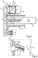
- a simplified height alignment of the slide rail 10 is provided with a in Fig. 7 achievable mounting set 38, which substantially the in Fig. 4 shown mounting kit 19 corresponds.
- this mounting kit 38 the web 22 is extended, and there is a second web 39 is provided, which is also perpendicular to a Base body of the stop member 21 extends and which runs as the first web 22 parallel to the slide rail 10.
- These two webs 22, 39 can be brought into abutment with an upper side of the guide nose 35 forming the upper guide groove 35 and with an underside of the guide nose 36 forming the lower guide groove 36. If then the webs 22, 39 slide along the guide lugs 34, a correct centering of the slide rail 10 in the vertical direction of the door 5 is provided.
- screw holes 40 which are provided in the region of a recess 41 in the slide rail 10, the positions are to be provided for in the furniture front plate 8 holes.
- the two outer of the equidistant in the well 41 arranged screw holes 40 are preferably used so that the slide rail 10 can tilt as little as possible.
- Fig. 8 shows accordingly separated from the stop member 21 and threaded into the guide grooves 35, 36 slide rail 10 before its attachment to the furniture front panel 8.
- the mounted on the furniture front panel 8 marks 43 are shown at which holes for attaching the slide rail 10 to the furniture front panel 8 can be drilled.
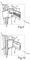
- the mounting kit 19 For screwing the slide rail 10 to the furniture front panel 8 (see Fig. 9 ) are provided in the mounting kit 19, two more screws 44 which are held in a storage device 45 of the mounting kit 19 (see Fig. 4 ).
- the storage device 45 is also held on retaining webs on the base body of the stop member 21.
- a cover element in the form of a cover plate 46 is presently held via a film hinge (see FIG Fig. 6 ).
- the cover plate 46 can be folded and thus the screw 27 are covered. This can be done before attaching the slide rail 10 on the furniture front panel 8 (see Fig. 6 ) or after attaching the slide rail 10 to the furniture front panel 8 (see Fig. 9 ).
- a lid 47 On the main body of the stop member 21, another cover member in the form of a lid 47 is held (see Fig. 4 ). With this cover 47, after screwing the slide rail 10 to the furniture front panel 8, the recess 41 provided in the slide rail 10 can be covered. For this purpose, the lid 47 is first separated from the mounting kit 19 and then preferably locked in the recess 41.
- the in Fig. 7 shown mounting kit 38 corresponds very much to the in Fig. 4
- the storage device 45, the lid 47 and the slide rail 10 are held on respective holding webs 42 on the main body of the stop member 21, and they are arranged side by side.
- the guide element 20 is arranged on the upper, first web 22, while extending parallel to the first web 22 extending second web 39 in the same direction as the slide rail 10th
- Fig. 10 shows the assembled towing device 9, wherein the guide member 20 is mounted on the door 5 and the slide rail 10 on the furniture front panel 8. Also is off Fig. 10 clearly seen how the lid 47, the screws 44 covered with which the slide rail 10 is fixed to the furniture front panel 8, and how the cover plate 46, the pre-mounted on the door 5 screw 27 covered when the cover plate 46 is closed and with the first leg 24th the guide element 20 is locked.
- the slide rail 10 on the furniture front panel 8 can be a simplified installation of Reach towing device 9.
- the furniture front panel 8 is securely fixed to the door 5 of the household appliance 1.
- the screws 44 for attaching the slide rail 10 to the furniture front panel 8 are stored for ease of assignment on the mounting kit 19, 38.
Landscapes
- Assembled Shelves (AREA)
- Support Devices For Sliding Doors (AREA)
Priority Applications (1)
| Application Number | Priority Date | Filing Date | Title |
|---|---|---|---|
| PL15194190T PL3032022T3 (pl) | 2014-12-08 | 2015-11-12 | Sposób montażu urządzenia ciągnącego i zestaw montażowy |
Applications Claiming Priority (1)
| Application Number | Priority Date | Filing Date | Title |
|---|---|---|---|
| DE102014225088.9A DE102014225088B4 (de) | 2014-12-08 | 2014-12-08 | Verfahren zum Montieren einer Schleppvorrichtung |
Publications (2)
| Publication Number | Publication Date |
|---|---|
| EP3032022A1 true EP3032022A1 (fr) | 2016-06-15 |
| EP3032022B1 EP3032022B1 (fr) | 2021-03-10 |
Family
ID=54557255
Family Applications (1)
| Application Number | Title | Priority Date | Filing Date |
|---|---|---|---|
| EP15194190.3A Active EP3032022B1 (fr) | 2014-12-08 | 2015-11-12 | Procede de montage d'un dispositif d'attelage et kit de montage |
Country Status (4)
| Country | Link |
|---|---|
| EP (1) | EP3032022B1 (fr) |
| CN (1) | CN205795320U (fr) |
| DE (1) | DE102014225088B4 (fr) |
| PL (1) | PL3032022T3 (fr) |
Cited By (3)
| Publication number | Priority date | Publication date | Assignee | Title |
|---|---|---|---|---|
| EP3789705A1 (fr) * | 2019-09-05 | 2021-03-10 | Electrolux Appliances Aktiebolag | Outil de montage pour un système de connexion d'une porte d'un appareil ménager intégré à une porte d'un meuble |
| US11359404B2 (en) | 2018-11-06 | 2022-06-14 | Milwaukee Electric Tool Corporation | Door hardware locating tool |
| EP4246069A1 (fr) * | 2022-03-18 | 2023-09-20 | Whirlpool Corporation | Mécanisme coulissant pour réfrigérateur intégré |
Families Citing this family (3)
| Publication number | Priority date | Publication date | Assignee | Title |
|---|---|---|---|---|
| CN106839620B (zh) * | 2017-01-18 | 2019-10-01 | 合肥华凌股份有限公司 | 嵌入式冰箱的门连接装置及嵌入式冰箱装置 |
| US11635248B2 (en) | 2021-06-18 | 2023-04-25 | Whirlpool Corporation | Built-in refrigerator |
| CN223106384U (zh) * | 2023-11-27 | 2025-07-15 | 合肥美的电冰箱有限公司 | 滑门机构、门体组件和制冷设备 |
Citations (7)
| Publication number | Priority date | Publication date | Assignee | Title |
|---|---|---|---|---|
| DE7520916U (fr) * | 1975-07-02 | 1975-11-06 | Licentia Gmbh | |
| JPH0510068A (ja) * | 1991-01-28 | 1993-01-19 | Mitsubishi Electric Corp | 冷蔵庫収納家具 |
| DE19644734C1 (de) | 1996-10-28 | 1998-05-07 | Bauknecht Hausgeraete | Verfahren zum Anbringen eines Türblattes an der Gerätetür eines eingebauten Haushalt-Einbaugerätes |
| EP0857929A1 (fr) | 1997-02-07 | 1998-08-12 | BSH Bosch und Siemens Hausgeräte GmbH | Réfrigérateur à encastrer dans une niche de meuble |
| DE19748679C1 (de) | 1997-11-04 | 1998-11-26 | Liebherr Hausgeraete | Befestigung eines Türblatts an einer Gerätetür |
| EP1145667B1 (fr) | 2000-04-11 | 2004-06-02 | ELECTROLUX HOME PRODUCTS ITALY S.p.A. | Procédé de fixation d'une porte de placard à une porte d'un réfrigérateur intégré |
| DE102011007410A1 (de) * | 2011-04-14 | 2012-10-18 | BSH Bosch und Siemens Hausgeräte GmbH | Einbau-Kältegrät mit einem Beschlagsbauteil |
-
2014
- 2014-12-08 DE DE102014225088.9A patent/DE102014225088B4/de active Active
-
2015
- 2015-11-12 PL PL15194190T patent/PL3032022T3/pl unknown
- 2015-11-12 EP EP15194190.3A patent/EP3032022B1/fr active Active
- 2015-12-08 CN CN201521008358.5U patent/CN205795320U/zh not_active Expired - Lifetime
Patent Citations (7)
| Publication number | Priority date | Publication date | Assignee | Title |
|---|---|---|---|---|
| DE7520916U (fr) * | 1975-07-02 | 1975-11-06 | Licentia Gmbh | |
| JPH0510068A (ja) * | 1991-01-28 | 1993-01-19 | Mitsubishi Electric Corp | 冷蔵庫収納家具 |
| DE19644734C1 (de) | 1996-10-28 | 1998-05-07 | Bauknecht Hausgeraete | Verfahren zum Anbringen eines Türblattes an der Gerätetür eines eingebauten Haushalt-Einbaugerätes |
| EP0857929A1 (fr) | 1997-02-07 | 1998-08-12 | BSH Bosch und Siemens Hausgeräte GmbH | Réfrigérateur à encastrer dans une niche de meuble |
| DE19748679C1 (de) | 1997-11-04 | 1998-11-26 | Liebherr Hausgeraete | Befestigung eines Türblatts an einer Gerätetür |
| EP1145667B1 (fr) | 2000-04-11 | 2004-06-02 | ELECTROLUX HOME PRODUCTS ITALY S.p.A. | Procédé de fixation d'une porte de placard à une porte d'un réfrigérateur intégré |
| DE102011007410A1 (de) * | 2011-04-14 | 2012-10-18 | BSH Bosch und Siemens Hausgeräte GmbH | Einbau-Kältegrät mit einem Beschlagsbauteil |
Cited By (3)
| Publication number | Priority date | Publication date | Assignee | Title |
|---|---|---|---|---|
| US11359404B2 (en) | 2018-11-06 | 2022-06-14 | Milwaukee Electric Tool Corporation | Door hardware locating tool |
| EP3789705A1 (fr) * | 2019-09-05 | 2021-03-10 | Electrolux Appliances Aktiebolag | Outil de montage pour un système de connexion d'une porte d'un appareil ménager intégré à une porte d'un meuble |
| EP4246069A1 (fr) * | 2022-03-18 | 2023-09-20 | Whirlpool Corporation | Mécanisme coulissant pour réfrigérateur intégré |
Also Published As
| Publication number | Publication date |
|---|---|
| DE102014225088B4 (de) | 2025-05-28 |
| PL3032022T3 (pl) | 2021-08-23 |
| DE102014225088A1 (de) | 2016-06-09 |
| EP3032022B1 (fr) | 2021-03-10 |
| CN205795320U (zh) | 2016-12-14 |
Similar Documents
| Publication | Publication Date | Title |
|---|---|---|
| EP3032022B1 (fr) | Procede de montage d'un dispositif d'attelage et kit de montage | |
| DE2922384C2 (de) | In eine Einbaunische eines Küchen-Hochschrankes o.dgl., einsetzbares Einbaugerät, insbesondere Kühl- oder Gefrierschrank | |
| DE3119571C2 (fr) | ||
| DE2514357C3 (de) | Beschlag zum verschwenkbaren Verbinden einer Möbelplatte mit einem feststehenden Möbelteil | |
| EP3625417B1 (fr) | Bras de commande réglable en longueur | |
| EP3346074B1 (fr) | Dispositif d'assemblage destiné à insérer des éléments de châssis dans des ouvertures des parois | |
| DE112016001573B4 (de) | Scharnier für eine möbeltür | |
| EP0637213B1 (fr) | Ferrure de fixation pour les panneaux avant de tiroirs | |
| WO2018033221A1 (fr) | Charnière de meuble | |
| WO2018147818A1 (fr) | Charnière pour meuble facile à monter | |
| DE4140781A1 (de) | Drehfluegelbeschlag vorzugsweise fuer moebeltueren o. dgl. | |
| EP3097373B1 (fr) | Procédé et outil d'aide au montage servant au montage d'une ferrure de porte coulissante | |
| DE60103585T2 (de) | Verfahren zur Befestigung einer Schranktür an die Tür eines eingebauten Kühlschrankes | |
| DE4018235C2 (fr) | ||
| DE19818814C2 (de) | Hausgerät für den Einbau in einen Möbelumbau | |
| EP2697582A2 (fr) | Appareil frigorifique encastrable comportant un élément de montage | |
| DE19644734C1 (de) | Verfahren zum Anbringen eines Türblattes an der Gerätetür eines eingebauten Haushalt-Einbaugerätes | |
| EP0698710B1 (fr) | Penture pour portes, fenêtres et similaires | |
| EP3002533B1 (fr) | Ensemble de fixation pour un appareil menager, appareil menager et procede de fixation d'un appareil menager | |
| EP3890555A1 (fr) | Composant de meuble et procédé de fabrication | |
| EP2108774B1 (fr) | Charnière | |
| DE102009033086A1 (de) | Türanbindung | |
| DE20120238U1 (de) | Montageplatte zur verstellbaren Halterung von Möbelscharnieren am Korpus von Möbelstücken | |
| DE202004017027U1 (de) | Installations-Bausatz zur Vorwand-Montage von sanitären Bauelementen sowie diesen Installations-Bausatz ... | |
| DE102017119702A1 (de) | Hilfsvorrichtung zur Positionierung eines Haushaltsgerätes |
Legal Events
| Date | Code | Title | Description |
|---|---|---|---|
| PUAI | Public reference made under article 153(3) epc to a published international application that has entered the european phase |
Free format text: ORIGINAL CODE: 0009012 |
|
| AK | Designated contracting states |
Kind code of ref document: A1 Designated state(s): AL AT BE BG CH CY CZ DE DK EE ES FI FR GB GR HR HU IE IS IT LI LT LU LV MC MK MT NL NO PL PT RO RS SE SI SK SM TR |
|
| AX | Request for extension of the european patent |
Extension state: BA ME |
|
| STAA | Information on the status of an ep patent application or granted ep patent |
Free format text: STATUS: REQUEST FOR EXAMINATION WAS MADE |
|
| 17P | Request for examination filed |
Effective date: 20161215 |
|
| RBV | Designated contracting states (corrected) |
Designated state(s): AL AT BE BG CH CY CZ DE DK EE ES FI FR GB GR HR HU IE IS IT LI LT LU LV MC MK MT NL NO PL PT RO RS SE SI SK SM TR |
|
| STAA | Information on the status of an ep patent application or granted ep patent |
Free format text: STATUS: EXAMINATION IS IN PROGRESS |
|
| 17Q | First examination report despatched |
Effective date: 20190828 |
|
| GRAP | Despatch of communication of intention to grant a patent |
Free format text: ORIGINAL CODE: EPIDOSNIGR1 |
|
| STAA | Information on the status of an ep patent application or granted ep patent |
Free format text: STATUS: GRANT OF PATENT IS INTENDED |
|
| INTG | Intention to grant announced |
Effective date: 20200728 |
|
| GRAJ | Information related to disapproval of communication of intention to grant by the applicant or resumption of examination proceedings by the epo deleted |
Free format text: ORIGINAL CODE: EPIDOSDIGR1 |
|
| STAA | Information on the status of an ep patent application or granted ep patent |
Free format text: STATUS: EXAMINATION IS IN PROGRESS |
|
| GRAS | Grant fee paid |
Free format text: ORIGINAL CODE: EPIDOSNIGR3 |
|
| STAA | Information on the status of an ep patent application or granted ep patent |
Free format text: STATUS: GRANT OF PATENT IS INTENDED |
|
| GRAP | Despatch of communication of intention to grant a patent |
Free format text: ORIGINAL CODE: EPIDOSNIGR1 |
|
| INTC | Intention to grant announced (deleted) | ||
| INTG | Intention to grant announced |
Effective date: 20201202 |
|
| GRAA | (expected) grant |
Free format text: ORIGINAL CODE: 0009210 |
|
| STAA | Information on the status of an ep patent application or granted ep patent |
Free format text: STATUS: THE PATENT HAS BEEN GRANTED |
|
| AK | Designated contracting states |
Kind code of ref document: B1 Designated state(s): AL AT BE BG CH CY CZ DE DK EE ES FI FR GB GR HR HU IE IS IT LI LT LU LV MC MK MT NL NO PL PT RO RS SE SI SK SM TR |
|
| REG | Reference to a national code |
Ref country code: GB Ref legal event code: FG4D Free format text: NOT ENGLISH |
|
| REG | Reference to a national code |
Ref country code: AT Ref legal event code: REF Ref document number: 1369979 Country of ref document: AT Kind code of ref document: T Effective date: 20210315 Ref country code: CH Ref legal event code: EP |
|
| REG | Reference to a national code |
Ref country code: IE Ref legal event code: FG4D Free format text: LANGUAGE OF EP DOCUMENT: GERMAN |
|
| REG | Reference to a national code |
Ref country code: DE Ref legal event code: R096 Ref document number: 502015014367 Country of ref document: DE |
|
| REG | Reference to a national code |
Ref country code: LT Ref legal event code: MG9D |
|
| PG25 | Lapsed in a contracting state [announced via postgrant information from national office to epo] |
Ref country code: LT Free format text: LAPSE BECAUSE OF FAILURE TO SUBMIT A TRANSLATION OF THE DESCRIPTION OR TO PAY THE FEE WITHIN THE PRESCRIBED TIME-LIMIT Effective date: 20210310 Ref country code: GR Free format text: LAPSE BECAUSE OF FAILURE TO SUBMIT A TRANSLATION OF THE DESCRIPTION OR TO PAY THE FEE WITHIN THE PRESCRIBED TIME-LIMIT Effective date: 20210611 Ref country code: FI Free format text: LAPSE BECAUSE OF FAILURE TO SUBMIT A TRANSLATION OF THE DESCRIPTION OR TO PAY THE FEE WITHIN THE PRESCRIBED TIME-LIMIT Effective date: 20210310 Ref country code: HR Free format text: LAPSE BECAUSE OF FAILURE TO SUBMIT A TRANSLATION OF THE DESCRIPTION OR TO PAY THE FEE WITHIN THE PRESCRIBED TIME-LIMIT Effective date: 20210310 Ref country code: BG Free format text: LAPSE BECAUSE OF FAILURE TO SUBMIT A TRANSLATION OF THE DESCRIPTION OR TO PAY THE FEE WITHIN THE PRESCRIBED TIME-LIMIT Effective date: 20210610 Ref country code: NO Free format text: LAPSE BECAUSE OF FAILURE TO SUBMIT A TRANSLATION OF THE DESCRIPTION OR TO PAY THE FEE WITHIN THE PRESCRIBED TIME-LIMIT Effective date: 20210610 |
|
| REG | Reference to a national code |
Ref country code: NL Ref legal event code: MP Effective date: 20210310 |
|
| PG25 | Lapsed in a contracting state [announced via postgrant information from national office to epo] |
Ref country code: LV Free format text: LAPSE BECAUSE OF FAILURE TO SUBMIT A TRANSLATION OF THE DESCRIPTION OR TO PAY THE FEE WITHIN THE PRESCRIBED TIME-LIMIT Effective date: 20210310 Ref country code: RS Free format text: LAPSE BECAUSE OF FAILURE TO SUBMIT A TRANSLATION OF THE DESCRIPTION OR TO PAY THE FEE WITHIN THE PRESCRIBED TIME-LIMIT Effective date: 20210310 Ref country code: SE Free format text: LAPSE BECAUSE OF FAILURE TO SUBMIT A TRANSLATION OF THE DESCRIPTION OR TO PAY THE FEE WITHIN THE PRESCRIBED TIME-LIMIT Effective date: 20210310 |
|
| PG25 | Lapsed in a contracting state [announced via postgrant information from national office to epo] |
Ref country code: NL Free format text: LAPSE BECAUSE OF FAILURE TO SUBMIT A TRANSLATION OF THE DESCRIPTION OR TO PAY THE FEE WITHIN THE PRESCRIBED TIME-LIMIT Effective date: 20210310 |
|
| PG25 | Lapsed in a contracting state [announced via postgrant information from national office to epo] |
Ref country code: SM Free format text: LAPSE BECAUSE OF FAILURE TO SUBMIT A TRANSLATION OF THE DESCRIPTION OR TO PAY THE FEE WITHIN THE PRESCRIBED TIME-LIMIT Effective date: 20210310 Ref country code: CZ Free format text: LAPSE BECAUSE OF FAILURE TO SUBMIT A TRANSLATION OF THE DESCRIPTION OR TO PAY THE FEE WITHIN THE PRESCRIBED TIME-LIMIT Effective date: 20210310 Ref country code: EE Free format text: LAPSE BECAUSE OF FAILURE TO SUBMIT A TRANSLATION OF THE DESCRIPTION OR TO PAY THE FEE WITHIN THE PRESCRIBED TIME-LIMIT Effective date: 20210310 |
|
| PG25 | Lapsed in a contracting state [announced via postgrant information from national office to epo] |
Ref country code: IS Free format text: LAPSE BECAUSE OF FAILURE TO SUBMIT A TRANSLATION OF THE DESCRIPTION OR TO PAY THE FEE WITHIN THE PRESCRIBED TIME-LIMIT Effective date: 20210710 Ref country code: SK Free format text: LAPSE BECAUSE OF FAILURE TO SUBMIT A TRANSLATION OF THE DESCRIPTION OR TO PAY THE FEE WITHIN THE PRESCRIBED TIME-LIMIT Effective date: 20210310 Ref country code: RO Free format text: LAPSE BECAUSE OF FAILURE TO SUBMIT A TRANSLATION OF THE DESCRIPTION OR TO PAY THE FEE WITHIN THE PRESCRIBED TIME-LIMIT Effective date: 20210310 Ref country code: PT Free format text: LAPSE BECAUSE OF FAILURE TO SUBMIT A TRANSLATION OF THE DESCRIPTION OR TO PAY THE FEE WITHIN THE PRESCRIBED TIME-LIMIT Effective date: 20210712 Ref country code: ES Free format text: LAPSE BECAUSE OF FAILURE TO SUBMIT A TRANSLATION OF THE DESCRIPTION OR TO PAY THE FEE WITHIN THE PRESCRIBED TIME-LIMIT Effective date: 20210310 |
|
| REG | Reference to a national code |
Ref country code: DE Ref legal event code: R097 Ref document number: 502015014367 Country of ref document: DE |
|
| PLBE | No opposition filed within time limit |
Free format text: ORIGINAL CODE: 0009261 |
|
| STAA | Information on the status of an ep patent application or granted ep patent |
Free format text: STATUS: NO OPPOSITION FILED WITHIN TIME LIMIT |
|
| PG25 | Lapsed in a contracting state [announced via postgrant information from national office to epo] |
Ref country code: DK Free format text: LAPSE BECAUSE OF FAILURE TO SUBMIT A TRANSLATION OF THE DESCRIPTION OR TO PAY THE FEE WITHIN THE PRESCRIBED TIME-LIMIT Effective date: 20210310 Ref country code: AL Free format text: LAPSE BECAUSE OF FAILURE TO SUBMIT A TRANSLATION OF THE DESCRIPTION OR TO PAY THE FEE WITHIN THE PRESCRIBED TIME-LIMIT Effective date: 20210310 |
|
| 26N | No opposition filed |
Effective date: 20211213 |
|
| PG25 | Lapsed in a contracting state [announced via postgrant information from national office to epo] |
Ref country code: SI Free format text: LAPSE BECAUSE OF FAILURE TO SUBMIT A TRANSLATION OF THE DESCRIPTION OR TO PAY THE FEE WITHIN THE PRESCRIBED TIME-LIMIT Effective date: 20210310 |
|
| PG25 | Lapsed in a contracting state [announced via postgrant information from national office to epo] |
Ref country code: IS Free format text: LAPSE BECAUSE OF FAILURE TO SUBMIT A TRANSLATION OF THE DESCRIPTION OR TO PAY THE FEE WITHIN THE PRESCRIBED TIME-LIMIT Effective date: 20210710 |
|
| PG25 | Lapsed in a contracting state [announced via postgrant information from national office to epo] |
Ref country code: MC Free format text: LAPSE BECAUSE OF FAILURE TO SUBMIT A TRANSLATION OF THE DESCRIPTION OR TO PAY THE FEE WITHIN THE PRESCRIBED TIME-LIMIT Effective date: 20210310 |
|
| REG | Reference to a national code |
Ref country code: CH Ref legal event code: PL |
|
| GBPC | Gb: european patent ceased through non-payment of renewal fee |
Effective date: 20211112 |
|
| PG25 | Lapsed in a contracting state [announced via postgrant information from national office to epo] |
Ref country code: LU Free format text: LAPSE BECAUSE OF NON-PAYMENT OF DUE FEES Effective date: 20211112 Ref country code: BE Free format text: LAPSE BECAUSE OF NON-PAYMENT OF DUE FEES Effective date: 20211130 |
|
| REG | Reference to a national code |
Ref country code: BE Ref legal event code: MM Effective date: 20211130 |
|
| PG25 | Lapsed in a contracting state [announced via postgrant information from national office to epo] |
Ref country code: IE Free format text: LAPSE BECAUSE OF NON-PAYMENT OF DUE FEES Effective date: 20211112 Ref country code: GB Free format text: LAPSE BECAUSE OF NON-PAYMENT OF DUE FEES Effective date: 20211112 |
|
| PG25 | Lapsed in a contracting state [announced via postgrant information from national office to epo] |
Ref country code: FR Free format text: LAPSE BECAUSE OF NON-PAYMENT OF DUE FEES Effective date: 20211130 |
|
| REG | Reference to a national code |
Ref country code: AT Ref legal event code: MM01 Ref document number: 1369979 Country of ref document: AT Kind code of ref document: T Effective date: 20211112 |
|
| PG25 | Lapsed in a contracting state [announced via postgrant information from national office to epo] |
Ref country code: AT Free format text: LAPSE BECAUSE OF NON-PAYMENT OF DUE FEES Effective date: 20211112 |
|
| PGFP | Annual fee paid to national office [announced via postgrant information from national office to epo] |
Ref country code: IT Payment date: 20221130 Year of fee payment: 8 |
|
| PG25 | Lapsed in a contracting state [announced via postgrant information from national office to epo] |
Ref country code: HU Free format text: LAPSE BECAUSE OF FAILURE TO SUBMIT A TRANSLATION OF THE DESCRIPTION OR TO PAY THE FEE WITHIN THE PRESCRIBED TIME-LIMIT; INVALID AB INITIO Effective date: 20151112 |
|
| PG25 | Lapsed in a contracting state [announced via postgrant information from national office to epo] |
Ref country code: CY Free format text: LAPSE BECAUSE OF FAILURE TO SUBMIT A TRANSLATION OF THE DESCRIPTION OR TO PAY THE FEE WITHIN THE PRESCRIBED TIME-LIMIT Effective date: 20210310 |
|
| PG25 | Lapsed in a contracting state [announced via postgrant information from national office to epo] |
Ref country code: LI Free format text: LAPSE BECAUSE OF NON-PAYMENT OF DUE FEES Effective date: 20220630 Ref country code: CH Free format text: LAPSE BECAUSE OF NON-PAYMENT OF DUE FEES Effective date: 20220630 |
|
| PG25 | Lapsed in a contracting state [announced via postgrant information from national office to epo] |
Ref country code: MK Free format text: LAPSE BECAUSE OF FAILURE TO SUBMIT A TRANSLATION OF THE DESCRIPTION OR TO PAY THE FEE WITHIN THE PRESCRIBED TIME-LIMIT Effective date: 20210310 |
|
| PG25 | Lapsed in a contracting state [announced via postgrant information from national office to epo] |
Ref country code: MT Free format text: LAPSE BECAUSE OF FAILURE TO SUBMIT A TRANSLATION OF THE DESCRIPTION OR TO PAY THE FEE WITHIN THE PRESCRIBED TIME-LIMIT Effective date: 20210310 |
|
| PG25 | Lapsed in a contracting state [announced via postgrant information from national office to epo] |
Ref country code: IT Free format text: LAPSE BECAUSE OF NON-PAYMENT OF DUE FEES Effective date: 20231112 |
|
| PG25 | Lapsed in a contracting state [announced via postgrant information from national office to epo] |
Ref country code: IT Free format text: LAPSE BECAUSE OF NON-PAYMENT OF DUE FEES Effective date: 20231112 |
|
| PGFP | Annual fee paid to national office [announced via postgrant information from national office to epo] |
Ref country code: DE Payment date: 20251130 Year of fee payment: 11 |
|
| PGFP | Annual fee paid to national office [announced via postgrant information from national office to epo] |
Ref country code: TR Payment date: 20251107 Year of fee payment: 11 |
|
| PGFP | Annual fee paid to national office [announced via postgrant information from national office to epo] |
Ref country code: PL Payment date: 20251107 Year of fee payment: 11 |