EP3032041A1 - Rotorhitzeschild und Verfahren zur Sicherung davon in einer Rotoranordnung - Google Patents
Rotorhitzeschild und Verfahren zur Sicherung davon in einer Rotoranordnung Download PDFInfo
- Publication number
- EP3032041A1 EP3032041A1 EP14196806.5A EP14196806A EP3032041A1 EP 3032041 A1 EP3032041 A1 EP 3032041A1 EP 14196806 A EP14196806 A EP 14196806A EP 3032041 A1 EP3032041 A1 EP 3032041A1
- Authority
- EP
- European Patent Office
- Prior art keywords
- rotor
- heat shield
- groove
- shield element
- rotor assembly
- Prior art date
- Legal status (The legal status is an assumption and is not a legal conclusion. Google has not performed a legal analysis and makes no representation as to the accuracy of the status listed.)
- Granted
Links
Images


Classifications
-
- F—MECHANICAL ENGINEERING; LIGHTING; HEATING; WEAPONS; BLASTING
- F01—MACHINES OR ENGINES IN GENERAL; ENGINE PLANTS IN GENERAL; STEAM ENGINES
- F01D—NON-POSITIVE DISPLACEMENT MACHINES OR ENGINES, e.g. STEAM TURBINES
- F01D5/00—Blades; Blade-carrying members; Heating, heat-insulating, cooling or antivibration means on the blades or the members
- F01D5/02—Blade-carrying members, e.g. rotors
- F01D5/08—Heating, heat-insulating or cooling means
-
- F—MECHANICAL ENGINEERING; LIGHTING; HEATING; WEAPONS; BLASTING
- F01—MACHINES OR ENGINES IN GENERAL; ENGINE PLANTS IN GENERAL; STEAM ENGINES
- F01D—NON-POSITIVE DISPLACEMENT MACHINES OR ENGINES, e.g. STEAM TURBINES
- F01D11/00—Preventing or minimising internal leakage of working-fluid, e.g. between stages
- F01D11/001—Preventing or minimising internal leakage of working-fluid, e.g. between stages for sealing space between stator blade and rotor
-
- F—MECHANICAL ENGINEERING; LIGHTING; HEATING; WEAPONS; BLASTING
- F01—MACHINES OR ENGINES IN GENERAL; ENGINE PLANTS IN GENERAL; STEAM ENGINES
- F01D—NON-POSITIVE DISPLACEMENT MACHINES OR ENGINES, e.g. STEAM TURBINES
- F01D11/00—Preventing or minimising internal leakage of working-fluid, e.g. between stages
- F01D11/005—Sealing means between non relatively rotating elements
- F01D11/006—Sealing the gap between rotor blades or blades and rotor
- F01D11/008—Sealing the gap between rotor blades or blades and rotor by spacer elements between the blades, e.g. independent interblade platforms
-
- F—MECHANICAL ENGINEERING; LIGHTING; HEATING; WEAPONS; BLASTING
- F02—COMBUSTION ENGINES; HOT-GAS OR COMBUSTION-PRODUCT ENGINE PLANTS
- F02C—GAS-TURBINE PLANTS; AIR INTAKES FOR JET-PROPULSION PLANTS; CONTROLLING FUEL SUPPLY IN AIR-BREATHING JET-PROPULSION PLANTS
- F02C7/00—Features, components parts, details or accessories, not provided for in, or of interest apart form groups F02C1/00 - F02C6/00; Air intakes for jet-propulsion plants
- F02C7/24—Heat or noise insulation
-
- F—MECHANICAL ENGINEERING; LIGHTING; HEATING; WEAPONS; BLASTING
- F05—INDEXING SCHEMES RELATING TO ENGINES OR PUMPS IN VARIOUS SUBCLASSES OF CLASSES F01-F04
- F05D—INDEXING SCHEME FOR ASPECTS RELATING TO NON-POSITIVE-DISPLACEMENT MACHINES OR ENGINES, GAS-TURBINES OR JET-PROPULSION PLANTS
- F05D2220/00—Application
- F05D2220/30—Application in turbines
- F05D2220/32—Application in turbines in gas turbines
-
- F—MECHANICAL ENGINEERING; LIGHTING; HEATING; WEAPONS; BLASTING
- F05—INDEXING SCHEMES RELATING TO ENGINES OR PUMPS IN VARIOUS SUBCLASSES OF CLASSES F01-F04
- F05D—INDEXING SCHEME FOR ASPECTS RELATING TO NON-POSITIVE-DISPLACEMENT MACHINES OR ENGINES, GAS-TURBINES OR JET-PROPULSION PLANTS
- F05D2230/00—Manufacture
- F05D2230/60—Assembly methods
-
- F—MECHANICAL ENGINEERING; LIGHTING; HEATING; WEAPONS; BLASTING
- F05—INDEXING SCHEMES RELATING TO ENGINES OR PUMPS IN VARIOUS SUBCLASSES OF CLASSES F01-F04
- F05D—INDEXING SCHEME FOR ASPECTS RELATING TO NON-POSITIVE-DISPLACEMENT MACHINES OR ENGINES, GAS-TURBINES OR JET-PROPULSION PLANTS
- F05D2240/00—Components
- F05D2240/20—Rotors
- F05D2240/24—Rotors for turbines
-
- F—MECHANICAL ENGINEERING; LIGHTING; HEATING; WEAPONS; BLASTING
- F05—INDEXING SCHEMES RELATING TO ENGINES OR PUMPS IN VARIOUS SUBCLASSES OF CLASSES F01-F04
- F05D—INDEXING SCHEME FOR ASPECTS RELATING TO NON-POSITIVE-DISPLACEMENT MACHINES OR ENGINES, GAS-TURBINES OR JET-PROPULSION PLANTS
- F05D2260/00—Function
- F05D2260/20—Heat transfer, e.g. cooling
- F05D2260/231—Preventing heat transfer
-
- F—MECHANICAL ENGINEERING; LIGHTING; HEATING; WEAPONS; BLASTING
- F05—INDEXING SCHEMES RELATING TO ENGINES OR PUMPS IN VARIOUS SUBCLASSES OF CLASSES F01-F04
- F05D—INDEXING SCHEME FOR ASPECTS RELATING TO NON-POSITIVE-DISPLACEMENT MACHINES OR ENGINES, GAS-TURBINES OR JET-PROPULSION PLANTS
- F05D2260/00—Function
- F05D2260/30—Retaining components in desired mutual position
Definitions
- the present invention generally relates to a rotor assembly, and in particular relates to an improved rotor heat shield element which provides an innovative configuration for securing the same into the rotor assembly.
- rotating machines typically have a rotor which has several rotor blade rows with a plurality of rotor blades, and generally also at least one rotor heat shield composed by a plurality of heat shield elements, wherein the rotor heat shield is arranged axially between two adjacent rotor blade rows.
- the heat shield elements are inserted sequentially into a correspondent groove engraved into the rotor assembly, such to form a circumferential heat shield.
- each heat shield element is circumferentially fixed by means of a lug disposed on a neighbouring blade, which is accommodated in a receiving slot formed on the heat shield element.
- the rotor heat shield element is secured to the rotor assembly in correspondence of the groove in which it is inserted.
- such connection is preferably achieved by means of a fixing plate, which does not interfere with the current assembly process of the rotor heat shield element.
- the present invention allows the removal of current fixation features on heat shields and blades, that is lugs and correspondent receiving slots respectively. Furthermore, since the heat shield is no longer connected to a blade but directly to the rotor assembly, there is more freedom in selecting the number of heat shield elements to be provided to form the circumferential heat shield.
- a rotor heat shield element for a rotor assembly of a gas turbine comprising a heat shield, a base feet adapted to be inserted into a correspondent groove in the rotor assembly, the base feet being connected to the heat shield through a connection plate, the rotor heat shield element comprising securing means adapted to secure the rotor heat shield element to the rotor assembly, wherein the securing means are configured to cooperate with the rotor assembly in correspondence of the groove for establishing such connection.
- the securing means comprises a through-opening internally defined in said base feet, the through-opening having an inlet located on a bottom wall of the base feet and an outlet on an opposed wall thereto, wherein the through-opening is internally shaped such to define at least one stepped region.
- the through-opening is disposed along a radial direction of the rotor assembly when the base feet is inserted in the groove.
- the through-opening may be T-shaped, L-shaped or alternatively U-shaped, It will be appreciated that other shapes may also be considered.
- the outlet may be located in the proximity the connection plate.
- the outlet is located in the proximity of a free end of the base feet.
- a rotor assembly for a gas turbine comprising a circumferential groove for receiving a plurality of base feet, wherein it further comprises rotor connection means configured to connect the base feet to the rotor assembly, the rotor connection means being located in correspondence of the groove.
- the rotor connection means comprises at least a recess located on a lateral wall of the groove.
- the rotor assembly further comprises a plurality of recesses equidistantly located on the lateral wall of the groove.
- a method for inserting and securing a rotor heat shield element into a rotor assembly including the steps of providing a rotor heat shield element comprising a base feet, wherein the base feet defines internally a through-opening having an inlet located on a bottom wall and an outlet on an opposed wall thereto of the base feet, the through-opening being internally shaped such to define at least one stepped region; inserting into the through-opening a fixing plate, the fixing plate having a shape adapted to substantially match the internal shape of said through-opening and comprising a blocking portion extending out from said outlet of the opposed wall when inserted into the base feet; introducing the rotor heat shield into a rotor assembly, the rotor assembly comprising a circumferential groove shaped such to receive said base feet, said groove further comprising at least a recess located on a lateral wall of the groove; positioning the rotor heat shield element in the groove such that the blocking portion of the fixing plate is substantially aligned with the
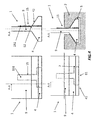
- the heat shield element 100 comprises connection means 101, in the form of receiving guides, which are adapted to host a lug provided on a correspondent blade, to which the heat shield element is secured.
- FIG. 2 This kind of connection, pertaining to the current practise, is schematically illustrated in next figure 2 .
- the rotor heat shield 100 is connected to a correspondent blade 200 by means of a lug 102 which is inserted into the receiving guide 101 of the shield element 100.
- the shield element is inserted into a circumferential groove 301 of the rotor assembly 300, and it is connected to the blade 200 which in turn is secured to the rotor assembly 300.
- the heat shield element 1 comprises a base feet 4, adapted to be inserted into a correspondent groove of a rotor assembly (not shown), and a connection plate 9 which links the base feet 4 to a heat shield (not depicted in the figure).
- the heat shield element 1 further comprises securing means 6 adapted to secure the heat shield element to the rotor assembly.
- the securing means 6 is advantageously configured to secure the heat shield element to the rotor assembly by cooperating with the groove in which the base feet 4 is inserted.
- the securing means 6 comprises a through-opening 6 which is internally defined in the base feet 4.
- the through-opening 6 has an inlet 61 located on a bottom wall 41 of the base feet 4 and an outlet 62 located on a wall 42 which is opposed to the bottom wall 41.
- the through-opening 6 is internally shaped such to define a stepped region 7.
- the through-opening 6 shown here in this example is T-shaped, having two stepped regions, but it will be appreciated that other shapes can be chosen, as long as they provide a stepped region.
- a u-shape may be selected, still providing two stepped regions, or alternatively an L-shaped may be considered, the latter providing only one stepped region.
- the through-opening 6 may be obtained, starting from the rotor heat shield element 1 depicted on top view, with methodologies known to those who are skilled in the art, like for example through a machining process.
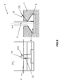
- FIG 4 there are shown the next steps necessary for securing the heat shield element 1 to a rotor assembly, now schematically depicted with numeral reference 2.
- a fixing plate 15 is then inserted into the through-opening 6.
- the fixing plate 15 has a shape which substantially matches the internal shape of the through-opening 6.
- the fixing plate 15 is subjected, during rotation of the rotor assembly, to an important centrifugal load.
- the stepped region 7 provided along the internal shape of the through-opening 6 is necessary to keep the fixing plate in position during operation of the machine.
- the fixing plate 15, in this non-limiting example, is T-shaped.
- the fixing plate 15 comprises a blocking portion 151 which extends out from the base feet 4, in particular from the outlet 62 of the wall 42.
- the through-opening 6 is disposed within the base feet 4 along a radial direction of the rotor assembly, when the heat shield element is inserted into the correspondent groove.
- the outlet 62 is located in the proximity of the connection plate 9, so that the fixing plate 15, and in particular the blocking element 151 lies adjacent to the connection plate 9.
- the outlet may be located anywhere along the opposed wall, and for example in the proximity of a free end of the base feet 4 (embodiment not shown).
- the blocking portion 151 is firstly bent along the wall 42 and then is straightened back following the vertical direction of the connection plate 9. Still making reference to figure 4 , bottom view, the heat shield element 1, including the fixing plate 15, is introduced into the rotor assembly 2.
- the rotor assembly 2 comprises a circumferential groove 5 adapted such to receive the base feet 4.
- the groove 5 of the rotor assembly 2 advantageously, comprises rotor connection means 10 which is configured to connect the base feet 4, and thus the rotor heat shield element 1, to the rotor assembly 2.
- the rotor connection means 10 is located in correspondence of the groove 5.
- the rotor connection means 10 comprises a recess 10, which is located on a lateral wall of the groove 5.
- the rotor heat shield element 1 is then positioned within the groove 5 such that the blocking portion 151 is substantially aligned with the recess 10. As a final step, the blocking portion 151 is bent towards the recess 10 to establish a solid connection between the rotor heat shield element 1 and the rotor assembly 2.
- the circumferential groove 5 of the rotor assembly 2 may comprises a plurality of recesses 10, equidistantly spaced along the lateral wall of the groove 5.
- the number of the recesses 10 engraved into the groove 5 may match the number of rotor heat shield elements 1 sequentially inserted into the groove 5, to finally form the complete circumferential heat shield. It will be appreciated that during such operation, each rotor heat shield element 1 is inserted into the groove 5 and positioned substantially in correspondence to the respective recess 10, in order to obtain the connection as above detailed.
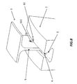
- the complete rotor heat shield element 1 is pictured, now showing also a heat shield 8, which is connected to the base feet 4 through the connection plate 9.
- the base feet comprises securing means 6, that is the through-opening 6 which, in this example, is T-shaped and defines internally two stepped regions.
- the fixing plate 15 is then inserted into the through-opening 6, such that the blocking portion 151 extends out from the base feet 4 and it is disposed adjacent to the connection plate 9, as shown in figure 7 .
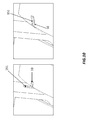
- the heat shield element 1 is introduced into the correspondent groove 5 of the rotor assembly 2, as shown in figure 8 .
- the element 1 is introduced such that the blocking element 151 is substantially aligned with the recess 10 engraved on the lateral wall of the groove 5.
- Figure 9 shows the final stage of the process when the blocking portion 151 is bent towards the recess 10. This way, circumferential movement of the rotor heat shield element 1 is prevented from the cooperation of the blocking portion 151 acting on the recess 10, whilst radial and axial movements of the element 1 are prevented by the cooperation of the base feet 4 inserted into the groove 5. This way stability of rotor heat shield element 1 is ensured.
- Last figure 10 shows in more detail the step of bending the blocking portion 151 into the recess 10.
- the fixing plate is made of metal. Indeed, such material is malleable and therefore can be deformed permanently without breaking or cracking. It will also be appreciated that the arrangement described above may be applied, mutatis mutandis, to any component which is installed radially by sliding components on a radial groove and that at the end of the assembly procedure further rotation of the components inside the groove needs to be completely avoided, so radially fixed, such as stator vanes or heat shields.
- through-opening 6 and rotor recess 10 may involve additional bending operations of the fixing plate against the base feet 4 and/or the connection plate 9. Such operations will occur after mounting the fixing plate 15 into the through-opening groove 6 and before mounting the rotor heat shield element 1 into the rotor assembly 2 in order to allow the rotor heat shield element 1 to slip along the circumferential groove 5 without the fixing plate 15 interfering.
- a second bending operation shall secure the fixing plate 15 into the rotor recess 10.
Landscapes
- Engineering & Computer Science (AREA)
- Mechanical Engineering (AREA)
- General Engineering & Computer Science (AREA)
- Chemical & Material Sciences (AREA)
- Combustion & Propulsion (AREA)
- Turbine Rotor Nozzle Sealing (AREA)
- Motor Or Generator Cooling System (AREA)
Priority Applications (2)
| Application Number | Priority Date | Filing Date | Title |
|---|---|---|---|
| EP14196806.5A EP3032041B1 (de) | 2014-12-08 | 2014-12-08 | Rotorhitzeschild und Verfahren zur Sicherung davon in einer Rotoranordnung |
| US14/960,183 US10156141B2 (en) | 2014-12-08 | 2015-12-04 | Rotor heat shield and method for securing the same into a rotor assembly |
Applications Claiming Priority (1)
| Application Number | Priority Date | Filing Date | Title |
|---|---|---|---|
| EP14196806.5A EP3032041B1 (de) | 2014-12-08 | 2014-12-08 | Rotorhitzeschild und Verfahren zur Sicherung davon in einer Rotoranordnung |
Publications (2)
| Publication Number | Publication Date |
|---|---|
| EP3032041A1 true EP3032041A1 (de) | 2016-06-15 |
| EP3032041B1 EP3032041B1 (de) | 2019-02-06 |
Family
ID=52103212
Family Applications (1)
| Application Number | Title | Priority Date | Filing Date |
|---|---|---|---|
| EP14196806.5A Active EP3032041B1 (de) | 2014-12-08 | 2014-12-08 | Rotorhitzeschild und Verfahren zur Sicherung davon in einer Rotoranordnung |
Country Status (2)
| Country | Link |
|---|---|
| US (1) | US10156141B2 (de) |
| EP (1) | EP3032041B1 (de) |
Families Citing this family (2)
| Publication number | Priority date | Publication date | Assignee | Title |
|---|---|---|---|---|
| WO2019008724A1 (ja) * | 2017-07-06 | 2019-01-10 | 東芝エネルギーシステムズ株式会社 | タービン |
| DE102017220336A1 (de) * | 2017-11-15 | 2019-05-16 | Siemens Aktiengesellschaft | Dichtsegment eines Rotors sowie Rotor |
Citations (4)
| Publication number | Priority date | Publication date | Assignee | Title |
|---|---|---|---|---|
| GB2280478A (en) * | 1993-07-31 | 1995-02-01 | Rolls Royce Plc | Gas turbine sealing assemblies. |
| GB2293628A (en) * | 1994-09-27 | 1996-04-03 | Europ Gas Turbines Ltd | Turbomachine rotor |
| EP1264964A1 (de) * | 2001-06-07 | 2002-12-11 | Snecma Moteurs | Anordung für einen Turbomachinenrotor mit zwei durch einen Abstandshalter getrennten Scheiben |
| US20100074731A1 (en) * | 2008-09-25 | 2010-03-25 | Wiebe David J | Gas Turbine Sealing Apparatus |
Family Cites Families (7)
| Publication number | Priority date | Publication date | Assignee | Title |
|---|---|---|---|---|
| CA2263508C (en) * | 1997-06-19 | 2003-08-19 | Mitsubishi Heavy Industries, Ltd. | Sealing device for gas turbine stator blades |
| JP3564286B2 (ja) * | 1997-12-08 | 2004-09-08 | 三菱重工業株式会社 | ガスタービン静翼の段間シールアクティブクリアランス制御システム |
| CA2619730A1 (en) * | 2005-08-23 | 2007-03-01 | Alstom Technology Ltd | Locking and fixing device for a heat shield element for a rotor unit of a turbomachine |
| US7566201B2 (en) * | 2007-01-30 | 2009-07-28 | Siemens Energy, Inc. | Turbine seal plate locking system |
| US8388309B2 (en) * | 2008-09-25 | 2013-03-05 | Siemens Energy, Inc. | Gas turbine sealing apparatus |
| US9376924B2 (en) * | 2011-12-14 | 2016-06-28 | United Technologies Corporation | Electrical grounding for fan blades |
| US9212559B2 (en) * | 2012-09-07 | 2015-12-15 | United Technologies Corporation | Electrical grounding for blades |
-
2014
- 2014-12-08 EP EP14196806.5A patent/EP3032041B1/de active Active
-
2015
- 2015-12-04 US US14/960,183 patent/US10156141B2/en active Active
Patent Citations (4)
| Publication number | Priority date | Publication date | Assignee | Title |
|---|---|---|---|---|
| GB2280478A (en) * | 1993-07-31 | 1995-02-01 | Rolls Royce Plc | Gas turbine sealing assemblies. |
| GB2293628A (en) * | 1994-09-27 | 1996-04-03 | Europ Gas Turbines Ltd | Turbomachine rotor |
| EP1264964A1 (de) * | 2001-06-07 | 2002-12-11 | Snecma Moteurs | Anordung für einen Turbomachinenrotor mit zwei durch einen Abstandshalter getrennten Scheiben |
| US20100074731A1 (en) * | 2008-09-25 | 2010-03-25 | Wiebe David J | Gas Turbine Sealing Apparatus |
Also Published As
| Publication number | Publication date |
|---|---|
| US10156141B2 (en) | 2018-12-18 |
| EP3032041B1 (de) | 2019-02-06 |
| US20160160649A1 (en) | 2016-06-09 |
Similar Documents
| Publication | Publication Date | Title |
|---|---|---|
| US10890196B2 (en) | Dummy ring assembly for removing vane segments, and method of removing vane segments using same | |
| EP2439378B1 (de) | Unterbindung des Verdrehens eines Turbinenschaufelsicherungsdrahts | |
| EP2899849B1 (de) | Statorbefestigungsstruktur | |
| EP2267868B1 (de) | Rotor für elektrische Permanentmagnetmaschine | |
| KR102273496B1 (ko) | 터빈 버킷 클로져 조립체 및 그 조립 방법 | |
| CN103375181B (zh) | 涡轮机组件 | |
| CN101550845A (zh) | 涡轮机叶片保持系统和方法 | |
| RU2601069C2 (ru) | Сопловой аппарат для турбины, способ установки лопаток в сопловой аппарат и паровая турбина | |
| US7114927B2 (en) | Fixing method for the blading of a fluid-flow machine and fixing arrangement | |
| US20080181778A1 (en) | Locking and fixing device for a heat shield element for a rotor unit of a turbomachine | |
| US8591192B2 (en) | Turbomachine rotor assembly and method | |
| KR20090052813A (ko) | 전기 기계 및 전기 기계용 로터 | |
| US10156141B2 (en) | Rotor heat shield and method for securing the same into a rotor assembly | |
| CN107075957A (zh) | 涡轮整体叶盘及其制造方法 | |
| US20150050135A1 (en) | Stator blade diaphragm ring, steam turbine and method | |
| US20140084740A1 (en) | Slot liner for electro-dynamic machine | |
| US3627448A (en) | Locking arrangement for side-entry blades | |
| EP2576998B1 (de) | Dampfturbineneinheit und Verfahren zur Montage einer Dampfturbine | |
| EP2949873A1 (de) | Turbomaschine mit Aufnahmeschutz und Verwendung der Turbomaschine | |
| EP3034798B1 (de) | Gasturbinenschaufel | |
| EP2557267B1 (de) | Verfahren zur Rekonditionierung eines Rotors einer Strömungsmaschine | |
| EP3412872B1 (de) | Statoranordnung für eine radial-axial expansionsstufe einer dampfturbine | |
| EP3015644B1 (de) | Dampfturbinenrotor | |
| EP4468568A1 (de) | Elektrische drehmaschine | |
| WO2019015824A1 (en) | ELECTRICAL GENERATOR WITH REDUCED END WRAPS |
Legal Events
| Date | Code | Title | Description |
|---|---|---|---|
| PUAI | Public reference made under article 153(3) epc to a published international application that has entered the european phase |
Free format text: ORIGINAL CODE: 0009012 |
|
| AK | Designated contracting states |
Kind code of ref document: A1 Designated state(s): AL AT BE BG CH CY CZ DE DK EE ES FI FR GB GR HR HU IE IS IT LI LT LU LV MC MK MT NL NO PL PT RO RS SE SI SK SM TR |
|
| AX | Request for extension of the european patent |
Extension state: BA ME |
|
| RAP1 | Party data changed (applicant data changed or rights of an application transferred) |
Owner name: GENERAL ELECTRIC TECHNOLOGY GMBH |
|
| STAA | Information on the status of an ep patent application or granted ep patent |
Free format text: STATUS: REQUEST FOR EXAMINATION WAS MADE |
|
| 17P | Request for examination filed |
Effective date: 20161215 |
|
| RBV | Designated contracting states (corrected) |
Designated state(s): AL AT BE BG CH CY CZ DE DK EE ES FI FR GB GR HR HU IE IS IT LI LT LU LV MC MK MT NL NO PL PT RO RS SE SI SK SM TR |
|
| RAP1 | Party data changed (applicant data changed or rights of an application transferred) |
Owner name: ANSALDO ENERGIA SWITZERLAND AG |
|
| GRAP | Despatch of communication of intention to grant a patent |
Free format text: ORIGINAL CODE: EPIDOSNIGR1 |
|
| STAA | Information on the status of an ep patent application or granted ep patent |
Free format text: STATUS: GRANT OF PATENT IS INTENDED |
|
| INTG | Intention to grant announced |
Effective date: 20180824 |
|
| GRAS | Grant fee paid |
Free format text: ORIGINAL CODE: EPIDOSNIGR3 |
|
| GRAA | (expected) grant |
Free format text: ORIGINAL CODE: 0009210 |
|
| STAA | Information on the status of an ep patent application or granted ep patent |
Free format text: STATUS: THE PATENT HAS BEEN GRANTED |
|
| AK | Designated contracting states |
Kind code of ref document: B1 Designated state(s): AL AT BE BG CH CY CZ DE DK EE ES FI FR GB GR HR HU IE IS IT LI LT LU LV MC MK MT NL NO PL PT RO RS SE SI SK SM TR |
|
| REG | Reference to a national code |
Ref country code: GB Ref legal event code: FG4D |
|
| REG | Reference to a national code |
Ref country code: CH Ref legal event code: EP Ref country code: AT Ref legal event code: REF Ref document number: 1095052 Country of ref document: AT Kind code of ref document: T Effective date: 20190215 |
|
| REG | Reference to a national code |
Ref country code: DE Ref legal event code: R096 Ref document number: 602014040685 Country of ref document: DE |
|
| REG | Reference to a national code |
Ref country code: IE Ref legal event code: FG4D |
|
| REG | Reference to a national code |
Ref country code: NL Ref legal event code: MP Effective date: 20190206 |
|
| REG | Reference to a national code |
Ref country code: LT Ref legal event code: MG4D |
|
| PG25 | Lapsed in a contracting state [announced via postgrant information from national office to epo] |
Ref country code: PT Free format text: LAPSE BECAUSE OF FAILURE TO SUBMIT A TRANSLATION OF THE DESCRIPTION OR TO PAY THE FEE WITHIN THE PRESCRIBED TIME-LIMIT Effective date: 20190606 Ref country code: FI Free format text: LAPSE BECAUSE OF FAILURE TO SUBMIT A TRANSLATION OF THE DESCRIPTION OR TO PAY THE FEE WITHIN THE PRESCRIBED TIME-LIMIT Effective date: 20190206 Ref country code: LT Free format text: LAPSE BECAUSE OF FAILURE TO SUBMIT A TRANSLATION OF THE DESCRIPTION OR TO PAY THE FEE WITHIN THE PRESCRIBED TIME-LIMIT Effective date: 20190206 Ref country code: SE Free format text: LAPSE BECAUSE OF FAILURE TO SUBMIT A TRANSLATION OF THE DESCRIPTION OR TO PAY THE FEE WITHIN THE PRESCRIBED TIME-LIMIT Effective date: 20190206 Ref country code: NL Free format text: LAPSE BECAUSE OF FAILURE TO SUBMIT A TRANSLATION OF THE DESCRIPTION OR TO PAY THE FEE WITHIN THE PRESCRIBED TIME-LIMIT Effective date: 20190206 Ref country code: NO Free format text: LAPSE BECAUSE OF FAILURE TO SUBMIT A TRANSLATION OF THE DESCRIPTION OR TO PAY THE FEE WITHIN THE PRESCRIBED TIME-LIMIT Effective date: 20190506 |
|
| REG | Reference to a national code |
Ref country code: AT Ref legal event code: MK05 Ref document number: 1095052 Country of ref document: AT Kind code of ref document: T Effective date: 20190206 |
|
| PG25 | Lapsed in a contracting state [announced via postgrant information from national office to epo] |
Ref country code: LV Free format text: LAPSE BECAUSE OF FAILURE TO SUBMIT A TRANSLATION OF THE DESCRIPTION OR TO PAY THE FEE WITHIN THE PRESCRIBED TIME-LIMIT Effective date: 20190206 Ref country code: GR Free format text: LAPSE BECAUSE OF FAILURE TO SUBMIT A TRANSLATION OF THE DESCRIPTION OR TO PAY THE FEE WITHIN THE PRESCRIBED TIME-LIMIT Effective date: 20190507 Ref country code: HR Free format text: LAPSE BECAUSE OF FAILURE TO SUBMIT A TRANSLATION OF THE DESCRIPTION OR TO PAY THE FEE WITHIN THE PRESCRIBED TIME-LIMIT Effective date: 20190206 Ref country code: IS Free format text: LAPSE BECAUSE OF FAILURE TO SUBMIT A TRANSLATION OF THE DESCRIPTION OR TO PAY THE FEE WITHIN THE PRESCRIBED TIME-LIMIT Effective date: 20190606 Ref country code: RS Free format text: LAPSE BECAUSE OF FAILURE TO SUBMIT A TRANSLATION OF THE DESCRIPTION OR TO PAY THE FEE WITHIN THE PRESCRIBED TIME-LIMIT Effective date: 20190206 Ref country code: BG Free format text: LAPSE BECAUSE OF FAILURE TO SUBMIT A TRANSLATION OF THE DESCRIPTION OR TO PAY THE FEE WITHIN THE PRESCRIBED TIME-LIMIT Effective date: 20190506 |
|
| PG25 | Lapsed in a contracting state [announced via postgrant information from national office to epo] |
Ref country code: EE Free format text: LAPSE BECAUSE OF FAILURE TO SUBMIT A TRANSLATION OF THE DESCRIPTION OR TO PAY THE FEE WITHIN THE PRESCRIBED TIME-LIMIT Effective date: 20190206 Ref country code: IT Free format text: LAPSE BECAUSE OF FAILURE TO SUBMIT A TRANSLATION OF THE DESCRIPTION OR TO PAY THE FEE WITHIN THE PRESCRIBED TIME-LIMIT Effective date: 20190206 Ref country code: CZ Free format text: LAPSE BECAUSE OF FAILURE TO SUBMIT A TRANSLATION OF THE DESCRIPTION OR TO PAY THE FEE WITHIN THE PRESCRIBED TIME-LIMIT Effective date: 20190206 Ref country code: RO Free format text: LAPSE BECAUSE OF FAILURE TO SUBMIT A TRANSLATION OF THE DESCRIPTION OR TO PAY THE FEE WITHIN THE PRESCRIBED TIME-LIMIT Effective date: 20190206 Ref country code: AL Free format text: LAPSE BECAUSE OF FAILURE TO SUBMIT A TRANSLATION OF THE DESCRIPTION OR TO PAY THE FEE WITHIN THE PRESCRIBED TIME-LIMIT Effective date: 20190206 Ref country code: ES Free format text: LAPSE BECAUSE OF FAILURE TO SUBMIT A TRANSLATION OF THE DESCRIPTION OR TO PAY THE FEE WITHIN THE PRESCRIBED TIME-LIMIT Effective date: 20190206 Ref country code: DK Free format text: LAPSE BECAUSE OF FAILURE TO SUBMIT A TRANSLATION OF THE DESCRIPTION OR TO PAY THE FEE WITHIN THE PRESCRIBED TIME-LIMIT Effective date: 20190206 Ref country code: SK Free format text: LAPSE BECAUSE OF FAILURE TO SUBMIT A TRANSLATION OF THE DESCRIPTION OR TO PAY THE FEE WITHIN THE PRESCRIBED TIME-LIMIT Effective date: 20190206 |
|
| REG | Reference to a national code |
Ref country code: DE Ref legal event code: R097 Ref document number: 602014040685 Country of ref document: DE |
|
| PG25 | Lapsed in a contracting state [announced via postgrant information from national office to epo] |
Ref country code: PL Free format text: LAPSE BECAUSE OF FAILURE TO SUBMIT A TRANSLATION OF THE DESCRIPTION OR TO PAY THE FEE WITHIN THE PRESCRIBED TIME-LIMIT Effective date: 20190206 Ref country code: SM Free format text: LAPSE BECAUSE OF FAILURE TO SUBMIT A TRANSLATION OF THE DESCRIPTION OR TO PAY THE FEE WITHIN THE PRESCRIBED TIME-LIMIT Effective date: 20190206 |
|
| PLBE | No opposition filed within time limit |
Free format text: ORIGINAL CODE: 0009261 |
|
| STAA | Information on the status of an ep patent application or granted ep patent |
Free format text: STATUS: NO OPPOSITION FILED WITHIN TIME LIMIT |
|
| PG25 | Lapsed in a contracting state [announced via postgrant information from national office to epo] |
Ref country code: AT Free format text: LAPSE BECAUSE OF FAILURE TO SUBMIT A TRANSLATION OF THE DESCRIPTION OR TO PAY THE FEE WITHIN THE PRESCRIBED TIME-LIMIT Effective date: 20190206 |
|
| 26N | No opposition filed |
Effective date: 20191107 |
|
| PG25 | Lapsed in a contracting state [announced via postgrant information from national office to epo] |
Ref country code: SI Free format text: LAPSE BECAUSE OF FAILURE TO SUBMIT A TRANSLATION OF THE DESCRIPTION OR TO PAY THE FEE WITHIN THE PRESCRIBED TIME-LIMIT Effective date: 20190206 |
|
| PG25 | Lapsed in a contracting state [announced via postgrant information from national office to epo] |
Ref country code: TR Free format text: LAPSE BECAUSE OF FAILURE TO SUBMIT A TRANSLATION OF THE DESCRIPTION OR TO PAY THE FEE WITHIN THE PRESCRIBED TIME-LIMIT Effective date: 20190206 |
|
| REG | Reference to a national code |
Ref country code: CH Ref legal event code: PL |
|
| REG | Reference to a national code |
Ref country code: BE Ref legal event code: MM Effective date: 20191231 |
|
| PG25 | Lapsed in a contracting state [announced via postgrant information from national office to epo] |
Ref country code: MC Free format text: LAPSE BECAUSE OF FAILURE TO SUBMIT A TRANSLATION OF THE DESCRIPTION OR TO PAY THE FEE WITHIN THE PRESCRIBED TIME-LIMIT Effective date: 20190206 |
|
| GBPC | Gb: european patent ceased through non-payment of renewal fee |
Effective date: 20191208 |
|
| PG25 | Lapsed in a contracting state [announced via postgrant information from national office to epo] |
Ref country code: LU Free format text: LAPSE BECAUSE OF NON-PAYMENT OF DUE FEES Effective date: 20191208 Ref country code: FR Free format text: LAPSE BECAUSE OF NON-PAYMENT OF DUE FEES Effective date: 20191231 Ref country code: IE Free format text: LAPSE BECAUSE OF NON-PAYMENT OF DUE FEES Effective date: 20191208 Ref country code: GB Free format text: LAPSE BECAUSE OF NON-PAYMENT OF DUE FEES Effective date: 20191208 |
|
| PG25 | Lapsed in a contracting state [announced via postgrant information from national office to epo] |
Ref country code: BE Free format text: LAPSE BECAUSE OF NON-PAYMENT OF DUE FEES Effective date: 20191231 Ref country code: CH Free format text: LAPSE BECAUSE OF NON-PAYMENT OF DUE FEES Effective date: 20191231 Ref country code: LI Free format text: LAPSE BECAUSE OF NON-PAYMENT OF DUE FEES Effective date: 20191231 |
|
| PG25 | Lapsed in a contracting state [announced via postgrant information from national office to epo] |
Ref country code: CY Free format text: LAPSE BECAUSE OF FAILURE TO SUBMIT A TRANSLATION OF THE DESCRIPTION OR TO PAY THE FEE WITHIN THE PRESCRIBED TIME-LIMIT Effective date: 20190206 |
|
| PG25 | Lapsed in a contracting state [announced via postgrant information from national office to epo] |
Ref country code: MT Free format text: LAPSE BECAUSE OF FAILURE TO SUBMIT A TRANSLATION OF THE DESCRIPTION OR TO PAY THE FEE WITHIN THE PRESCRIBED TIME-LIMIT Effective date: 20190206 Ref country code: HU Free format text: LAPSE BECAUSE OF FAILURE TO SUBMIT A TRANSLATION OF THE DESCRIPTION OR TO PAY THE FEE WITHIN THE PRESCRIBED TIME-LIMIT; INVALID AB INITIO Effective date: 20141208 |
|
| PG25 | Lapsed in a contracting state [announced via postgrant information from national office to epo] |
Ref country code: MK Free format text: LAPSE BECAUSE OF FAILURE TO SUBMIT A TRANSLATION OF THE DESCRIPTION OR TO PAY THE FEE WITHIN THE PRESCRIBED TIME-LIMIT Effective date: 20190206 |
|
| P01 | Opt-out of the competence of the unified patent court (upc) registered |
Effective date: 20240430 |
|
| PGFP | Annual fee paid to national office [announced via postgrant information from national office to epo] |
Ref country code: DE Payment date: 20251222 Year of fee payment: 12 |