EP3032074A1 - Boîtier d'accessoires avec deux arbres d'entraînement pour turbine à gaz - Google Patents
Boîtier d'accessoires avec deux arbres d'entraînement pour turbine à gaz Download PDFInfo
- Publication number
- EP3032074A1 EP3032074A1 EP15199411.8A EP15199411A EP3032074A1 EP 3032074 A1 EP3032074 A1 EP 3032074A1 EP 15199411 A EP15199411 A EP 15199411A EP 3032074 A1 EP3032074 A1 EP 3032074A1
- Authority
- EP
- European Patent Office
- Prior art keywords
- shafts
- tower
- gas turbine
- housing
- gears
- Prior art date
- Legal status (The legal status is an assumption and is not a legal conclusion. Google has not performed a legal analysis and makes no representation as to the accuracy of the status listed.)
- Withdrawn
Links
Images


Classifications
-
- F—MECHANICAL ENGINEERING; LIGHTING; HEATING; WEAPONS; BLASTING
- F02—COMBUSTION ENGINES; HOT-GAS OR COMBUSTION-PRODUCT ENGINE PLANTS
- F02C—GAS-TURBINE PLANTS; AIR INTAKES FOR JET-PROPULSION PLANTS; CONTROLLING FUEL SUPPLY IN AIR-BREATHING JET-PROPULSION PLANTS
- F02C7/00—Features, components parts, details or accessories, not provided for in, or of interest apart form groups F02C1/00 - F02C6/00; Air intakes for jet-propulsion plants
- F02C7/32—Arrangement, mounting, or driving, of auxiliaries
-
- F—MECHANICAL ENGINEERING; LIGHTING; HEATING; WEAPONS; BLASTING
- F02—COMBUSTION ENGINES; HOT-GAS OR COMBUSTION-PRODUCT ENGINE PLANTS
- F02C—GAS-TURBINE PLANTS; AIR INTAKES FOR JET-PROPULSION PLANTS; CONTROLLING FUEL SUPPLY IN AIR-BREATHING JET-PROPULSION PLANTS
- F02C7/00—Features, components parts, details or accessories, not provided for in, or of interest apart form groups F02C1/00 - F02C6/00; Air intakes for jet-propulsion plants
- F02C7/36—Power transmission arrangements between the different shafts of the gas turbine plant, or between the gas-turbine plant and the power user
-
- F—MECHANICAL ENGINEERING; LIGHTING; HEATING; WEAPONS; BLASTING
- F05—INDEXING SCHEMES RELATING TO ENGINES OR PUMPS IN VARIOUS SUBCLASSES OF CLASSES F01-F04
- F05D—INDEXING SCHEME FOR ASPECTS RELATING TO NON-POSITIVE-DISPLACEMENT MACHINES OR ENGINES, GAS-TURBINES OR JET-PROPULSION PLANTS
- F05D2230/00—Manufacture
- F05D2230/60—Assembly methods
-
- F—MECHANICAL ENGINEERING; LIGHTING; HEATING; WEAPONS; BLASTING
- F05—INDEXING SCHEMES RELATING TO ENGINES OR PUMPS IN VARIOUS SUBCLASSES OF CLASSES F01-F04
- F05D—INDEXING SCHEME FOR ASPECTS RELATING TO NON-POSITIVE-DISPLACEMENT MACHINES OR ENGINES, GAS-TURBINES OR JET-PROPULSION PLANTS
- F05D2230/00—Manufacture
- F05D2230/60—Assembly methods
- F05D2230/64—Assembly methods using positioning or alignment devices for aligning or centring, e.g. pins
- F05D2230/644—Assembly methods using positioning or alignment devices for aligning or centring, e.g. pins for adjusting the position or the alignment, e.g. wedges or eccenters
-
- F—MECHANICAL ENGINEERING; LIGHTING; HEATING; WEAPONS; BLASTING
- F05—INDEXING SCHEMES RELATING TO ENGINES OR PUMPS IN VARIOUS SUBCLASSES OF CLASSES F01-F04
- F05D—INDEXING SCHEME FOR ASPECTS RELATING TO NON-POSITIVE-DISPLACEMENT MACHINES OR ENGINES, GAS-TURBINES OR JET-PROPULSION PLANTS
- F05D2240/00—Components
- F05D2240/40—Use of a multiplicity of similar components
-
- F—MECHANICAL ENGINEERING; LIGHTING; HEATING; WEAPONS; BLASTING
- F05—INDEXING SCHEMES RELATING TO ENGINES OR PUMPS IN VARIOUS SUBCLASSES OF CLASSES F01-F04
- F05D—INDEXING SCHEME FOR ASPECTS RELATING TO NON-POSITIVE-DISPLACEMENT MACHINES OR ENGINES, GAS-TURBINES OR JET-PROPULSION PLANTS
- F05D2250/00—Geometry
- F05D2250/30—Arrangement of components
- F05D2250/31—Arrangement of components according to the direction of their main axis or their axis of rotation
- F05D2250/314—Arrangement of components according to the direction of their main axis or their axis of rotation the axes being inclined in relation to each other
-
- F—MECHANICAL ENGINEERING; LIGHTING; HEATING; WEAPONS; BLASTING
- F05—INDEXING SCHEMES RELATING TO ENGINES OR PUMPS IN VARIOUS SUBCLASSES OF CLASSES F01-F04
- F05D—INDEXING SCHEME FOR ASPECTS RELATING TO NON-POSITIVE-DISPLACEMENT MACHINES OR ENGINES, GAS-TURBINES OR JET-PROPULSION PLANTS
- F05D2260/00—Function
- F05D2260/40—Transmission of power
- F05D2260/403—Transmission of power through the shape of the drive components
- F05D2260/4031—Transmission of power through the shape of the drive components as in toothed gearing
Definitions
- This disclosure relates to an accessory drive gearbox for a gas turbine engine.
- a gas turbine engine typically includes a fan section, a compressor section, a combustor section and a turbine section. Air entering the compressor section is compressed and delivered into the combustor section where it is mixed with fuel and ignited to generate a high-speed exhaust gas flow. The high-speed exhaust gas flow expands through the turbine section to drive the compressor and the fan section.
- the compressor section typically includes low and high pressure compressors, and the turbine section includes low and high pressure turbines.
- a typical gas turbine engine utilizes one or more gearboxes to drive accessory components, such as generators, fuel pumps and oil pumps.
- accessory components such as generators, fuel pumps and oil pumps.
- Each of the accessory drive components must be driven at a desired rotational speed.
- the accessory is coupled to either the low or high speed spool and geared accordingly to obtain the speed at which the accessory operates more efficiently.
- gearbox has been proposed in which both high and low speed accessory drive components are driven by a single tower shaft. Gearing within the gearbox obtains a desired rotational speed and direction for each of the accessory drive components.
- a gas turbine engine in one exemplary embodiment, includes a turbine section that has first and second turbines mounted for rotation about a common rotational axis within an engine static structure.
- First and second turbine shafts coaxial with one another and to which the first and second turbines are respectively operatively mounted.
- First and second tower shafts respectively coupled to the first and second turbine shafts.
- An accessory drive gearbox is mounted to the engine static structure.
- the accessory drive gearbox includes gears arranged within a common housing.
- the first and second tower shafts extend into the common housing and are coupled to the gears.
- first and second turbine shafts are inner and outer shafts, respectively.
- the first and second turbines are low and high pressure turbines, respectively.
- the second tower shaft is configured to rotate at a higher speed than the first tower shaft.
- a first set of accessories are configured to be rotationally driven by the first tower shaft.
- a second set of accessories are configured to be rotationally driven by the second tower shaft.
- the first set of accessories includes at least one of a generator, a deoiler and a hydraulic pump.
- the second set of accessories includes at least one of a generator, a fuel pump, an oil pump and a permanent magnet alternator.
- first and second tower shafts extend in a generally radial direction from the rotational axis.
- the first and second tower shafts are arranged at an angle circumferentially relative to one another.
- the angle is less than 90°.
- the gears include first and second sets of gears respectively coupled to the first and second tower shafts.
- the the first set of gears is not in meshing engagement with the second set of gears.
- At least a portion of the first and second sets of gears circumferentially overlap one another.
- the housing includes a locating feature that is configured to circumferentially locate and align at least one of the first and second tower shafts relative to at least one of the first and second turbine shafts.
- the locating feature includes a bore and a first cover that has an eccentric pilot received in the bore.
- the first cover includes a hole and is rotatable within the bore to reposition the hole relative to the housing.
- the hole supports one of the first and second tower shafts.
- the housing includes a second cover opposite the first cover and is configured to facilitate insertion of one of the first and second tower shafts into the housing during assembly.
- a method of installing an accessory gearbox onto a gas turbine engine includes the steps of mounting a gearbox housing onto an engine static structure.
- the gearbox housing has first and second opposing sides.
- a first tower shaft is inserted into the first side of the housing, through the second side, and into the engine static structure to couple the first tower shaft with a first turbine shaft in the static structure and a first gear set in the gearbox housing.
- a second tower shaft is inserted into the first side of the housing, through the second side, and into the engine static structure to couple the second tower shaft with a second turbine shaft in the static structure and a second gear set in the gearbox housing.
- the first set of gears is not in meshing engagement with the second set of gears.
- the method includes the step of adjusting a position of a locating feature to circumferentially locate and align at least one of the first and second tower shafts relative to at least one of the first and second turbine shafts.
- a turbine section has first and second turbines mounted for rotation about a common rotational axis within the engine static structure.
- the first and second turbine shafts coaxial with one another and to which the first and second turbines are respectively operatively mounted.
- the first and second turbine shafts are inner and outer shafts, respectively.
- the first and second turbines are low and high pressure turbines, respectively.
- the second tower shaft is configured to rotate at a higher speed than the first tower shaft.
- the inserting steps include installing the first and second tower shafts in a generally radial direction relative to the rotational axis.
- the first and second tower shafts are at an acute angle circumferentially relative to one another.
- the method includes the step of mounting first and second sets of accessories to the gearbox.
- the first set of accessories includes at least one of a generator, a deoiler and a hydraulic pump.
- the second set of accessories includes at least one of a generator, a fuel pump, an oil pump and a permanent magnet alternator.
- FIG. 1 schematically illustrates a gas turbine engine 20.
- the gas turbine engine 20 is disclosed herein as a two-spool turbofan that generally incorporates a fan section 22, a compressor section 24, a combustor section 26 and a turbine section 28.
- Alternative engines might include an augmenter section (not shown) among other systems or features.
- the fan section 22 drives air along a bypass flow path B in a bypass duct defined within a nacelle 15, while the compressor section 24 drives air along a core flow path C for compression and communication into the combustor section 26 then expansion through the turbine section 28.
- the exemplary engine 20 generally includes a low speed spool 30 and a high speed spool 32 mounted for rotation about an engine central longitudinal axis X relative to an engine static structure 36 via several bearing systems 38. It should be understood that various bearing systems 38 at various locations may alternatively or additionally be provided, and the location of bearing systems 38 may be varied as appropriate to the application.
- the low speed spool 30 generally includes an inner shaft 40 that interconnects a fan 42, a first (or low) pressure compressor 44 and a first (or low) pressure turbine 46.
- the inner shaft 40 is connected to the fan 42 through a speed change mechanism, which in exemplary gas turbine engine 20 is illustrated as a geared architecture 48 to drive the fan 42 at a lower speed than the low speed spool 30.
- the high speed spool 32 includes an outer shaft 50 that interconnects a second (or high) pressure compressor 52 and a second (or high) pressure turbine 54.
- a combustor 56 is arranged in exemplary gas turbine 20 between the high pressure compressor 52 and the high pressure turbine 54.
- a mid-turbine frame 57 of the engine static structure 36 is arranged generally between the high pressure turbine 54 and the low pressure turbine 46.
- the mid-turbine frame 57 further supports bearing systems 38 in the turbine section 28.
- the inner shaft 40 and the outer shaft 50 are concentric and rotate via bearing systems 38 about the engine central longitudinal axis X which is collinear with their longitudinal axes.
- the core airflow is compressed by the low pressure compressor 44 then the high pressure compressor 52, mixed and burned with fuel in the combustor 56, then expanded over the high pressure turbine 54 and low pressure turbine 46.
- the mid-turbine frame 57 includes airfoils 59 which are in the core airflow path C.
- the turbines 46, 54 rotationally drive the respective low speed spool 30 and high speed spool 32 in response to the expansion.
- gear system 48 may be located aft of combustor section 26 or even aft of turbine section 28, and fan section 22 may be positioned forward or aft of the location of gear system 48.
- the engine 20 in one example is a high-bypass geared aircraft engine.
- the engine 20 bypass ratio is greater than about six (6), with an example embodiment being greater than about ten (10)
- the geared architecture 48 is an epicyclic gear train, such as a planetary gear system or other gear system, with a gear reduction ratio of greater than about 2.3
- the low pressure turbine 46 has a pressure ratio that is greater than about five.
- the engine 20 bypass ratio is greater than about ten (10:1)
- the fan diameter is significantly larger than that of the low pressure compressor 44
- the low pressure turbine 46 has a pressure ratio that is greater than about five 5:1.
- Low pressure turbine 46 pressure ratio is pressure measured prior to inlet of low pressure turbine 46 as related to the pressure at the outlet of the low pressure turbine 46 prior to an exhaust nozzle.
- the geared architecture 48 may be an epicycle gear train, such as a planetary gear system or other gear system, with a gear reduction ratio of greater than about 2.3:1. It should be understood, however, that the above parameters are only exemplary of one embodiment of a geared architecture engine and that the present invention is applicable to other gas turbine engines including direct drive turbofans.
- the fan section 22 of the engine 20 is designed for a particular flight condition -- typically cruise at about 0.8 Mach and about 35,000 feet (10,668 meters).
- the flight condition of 0.8 Mach and 35,000 ft (10,668 meters), with the engine at its best fuel consumption - also known as "bucket cruise Thrust Specific Fuel Consumption ('TSFC')" - is the industry standard parameter of lbm of fuel being burned divided by lbf of thrust the engine produces at that minimum point.
- "Low fan pressure ratio” is the pressure ratio across the fan blade alone, without a Fan Exit Guide Vane (“FEGV”) system.
- the low fan pressure ratio as disclosed herein according to one non-limiting embodiment is less than about 1.45.
- Low corrected fan tip speed is the actual fan tip speed in ft/sec divided by an industry standard temperature correction of [(Tram °R) / (518.7 °R)] 0.5 .
- the "Low corrected fan tip speed” as disclosed herein according to one non-limiting embodiment is less than about 1150 ft / second (350.5 meters/second).
- the engine 10 includes an accessory drive gearbox 60, or gearbox, that is rotationally driven by both the inner and outer shafts 40, 52.
- the gearbox 60 includes a housing 62 within which first and second sets of gears 64, 66 are arranged.
- a first tower shaft 68 interconnects the inner shaft 42 to the first set of gears 64, and a second tower shaft 70 interconnects the outer shaft 52 to the second set of gears 66.
- the engine static structure 36 includes first bracket 74, and the gearbox 60 includes second bracket 76.
- Multiple mounting rods 78 are used to connect the first and second brackets 74, 76 to one another and mount the gearbox 60 relative to the engine static structure 36.
- the rods 78 may be adjustable to position the tower shafts 68, 70 relative to the engine static structure 36.
- the gearbox 60 includes first and second opposing sides 80, 82.
- the first and second tower shafts 68, 70 are inserted (shown in Figure 3 ) into the first side 80 of the housing 62 and through the second side 82 into the engine static structure 36.
- the first and second tower shafts can be installed in a generally radial direction from the rotational axis X such that the first and second tower shafts 68, 70 form an angle circumferentially relative to one another. In the example shown, the angle is less than 90°.
- the housing 62 includes first and second opposing faces 84, 86 to which first and second sets of accessory drive components 88, 90 are mounted and arranged generally longitudinally in the direction of the engine's axis X.
- the first set of accessory drive components 88 includes a generator 92, a deoiler 94, and a hydraulic pump 96.
- the second set of accessory drive components 90 include another generator 98, a fuel pump 100, an oil pump 102, and a permanent magnet alternator 104, for example.
- the first set of accessory drive components 88 are driven by the first tower shaft 68 through the first set of gears 64, and the second set of accessory drive components 90 is driven by the second tower shaft 70 through the second set of gears 66.
- the first set of gears 64 do not mesh with the second sets of gears 66. That is, the second set of gears 66 do not receive any rotational input from the first tower shaft 68, and the first set of gears 64 do not receive any rotational input from the second tower shaft 70. To provide a more compact package, at least a portion of the first and second sets of gears 64, 66 circumferentially overlap one another, as best shown in Figure 5B .
- the first tower shaft 68 is inserted through a first stub shaft 106, which is coupled to a first bevel gear 110.
- the first stub shaft 106 includes a first splined hole 114 that meshes with an end of the first tower shaft 68 once inserted into the gearbox 60.
- the gearbox 60 includes a second stub shaft 108 coupled to a second bevel gear 112.
- the second stub shaft 108 includes a second splined hole 116, which is interconnected to the second tower shaft 70 once installed.
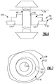
- the tower shafts 68, 70 extend through first covers 118 mounted on the first side 80, shown in Figure 4 . Second covers 120 are arranged over apertures in the second side 82, shown in Figure 5A , once the tower shafts 68, 70 have been installed into the gearbox 60.
- the locating feature 128 includes a bore 122 in a housing portion 130 of the housing 62.
- the first cover 118 includes an eccentric pilot 124 with respect to a hole 126 that receives the tower shaft.
- the first cover 118 may be rotated with respect to the housing portion 130 to reposition the hole 126 and its supported tower shaft. In this manner, slight positional adjustments of the tower shaft may be provided.
- This locating feature may be provided on the engine static structure 36 instead of or in addition to providing this feature on the gearbox 60.
Landscapes
- Engineering & Computer Science (AREA)
- Chemical & Material Sciences (AREA)
- Combustion & Propulsion (AREA)
- Mechanical Engineering (AREA)
- General Engineering & Computer Science (AREA)
- General Details Of Gearings (AREA)
Applications Claiming Priority (1)
| Application Number | Priority Date | Filing Date | Title |
|---|---|---|---|
| US201462091054P | 2014-12-12 | 2014-12-12 |
Publications (1)
| Publication Number | Publication Date |
|---|---|
| EP3032074A1 true EP3032074A1 (fr) | 2016-06-15 |
Family
ID=54849517
Family Applications (1)
| Application Number | Title | Priority Date | Filing Date |
|---|---|---|---|
| EP15199411.8A Withdrawn EP3032074A1 (fr) | 2014-12-12 | 2015-12-10 | Boîtier d'accessoires avec deux arbres d'entraînement pour turbine à gaz |
Country Status (2)
| Country | Link |
|---|---|
| US (1) | US20160169118A1 (fr) |
| EP (1) | EP3032074A1 (fr) |
Cited By (8)
| Publication number | Priority date | Publication date | Assignee | Title |
|---|---|---|---|---|
| EP2610463B1 (fr) | 2011-12-30 | 2016-08-03 | United Technologies Corporation | Train d'engrenages de moteur à turbine à gaz |
| EP3282093A1 (fr) * | 2016-08-09 | 2018-02-14 | United Technologies Corporation | Turboréacteur à engrenages avec prélèvement de puissance du corps basse pression |
| EP3354881A1 (fr) * | 2017-01-19 | 2018-08-01 | United Technologies Corporation | Boîte d'engrenages d'accessoires à deux arbres d'entraînement de moteur à turbine à gaz et ensemble générateur de démarreur |
| EP3388650A1 (fr) * | 2017-04-11 | 2018-10-17 | United Technologies Corporation | Entraînement de boîtier d'accessoire à arbre de transmission haute et basse pression |
| EP3388651A1 (fr) * | 2017-04-11 | 2018-10-17 | United Technologies Corporation | Ensemble boîte de vitesses de moteur de turbine avec des ensembles d'engrenages en ligne |
| EP3431738A1 (fr) * | 2017-04-27 | 2019-01-23 | United Technologies Corporation | Entraînement tangentiel pour accessoires de moteur de turbine à gaz |
| EP3696391A1 (fr) * | 2019-02-13 | 2020-08-19 | United Technologies Corporation | Boîte de vitesse accessoire pour moteur à turbine à gaz à transmission variable |
| CN111577451A (zh) * | 2020-05-22 | 2020-08-25 | 中国航发沈阳发动机研究所 | 一种发动机功率提取结构及其操纵方法 |
Families Citing this family (37)
| Publication number | Priority date | Publication date | Assignee | Title |
|---|---|---|---|---|
| US10640228B2 (en) * | 2013-02-22 | 2020-05-05 | United Technologies Corporation | Auxiliary power unit mounting bracket |
| US10731560B2 (en) | 2015-02-12 | 2020-08-04 | Raytheon Technologies Corporation | Intercooled cooling air |
| US10371055B2 (en) | 2015-02-12 | 2019-08-06 | United Technologies Corporation | Intercooled cooling air using cooling compressor as starter |
| US11808210B2 (en) | 2015-02-12 | 2023-11-07 | Rtx Corporation | Intercooled cooling air with heat exchanger packaging |
| US10830148B2 (en) | 2015-04-24 | 2020-11-10 | Raytheon Technologies Corporation | Intercooled cooling air with dual pass heat exchanger |
| US10480419B2 (en) | 2015-04-24 | 2019-11-19 | United Technologies Corporation | Intercooled cooling air with plural heat exchangers |
| US10221862B2 (en) | 2015-04-24 | 2019-03-05 | United Technologies Corporation | Intercooled cooling air tapped from plural locations |
| US10100739B2 (en) | 2015-05-18 | 2018-10-16 | United Technologies Corporation | Cooled cooling air system for a gas turbine engine |
| US10794288B2 (en) | 2015-07-07 | 2020-10-06 | Raytheon Technologies Corporation | Cooled cooling air system for a turbofan engine |
| US10443508B2 (en) | 2015-12-14 | 2019-10-15 | United Technologies Corporation | Intercooled cooling air with auxiliary compressor control |
| US10883424B2 (en) | 2016-07-19 | 2021-01-05 | Pratt & Whitney Canada Corp. | Multi-spool gas turbine engine architecture |
| US11415063B2 (en) | 2016-09-15 | 2022-08-16 | Pratt & Whitney Canada Corp. | Reverse-flow gas turbine engine |
| US11035293B2 (en) | 2016-09-15 | 2021-06-15 | Pratt & Whitney Canada Corp. | Reverse flow gas turbine engine with offset RGB |
| US10465611B2 (en) | 2016-09-15 | 2019-11-05 | Pratt & Whitney Canada Corp. | Reverse flow multi-spool gas turbine engine with aft-end accessory gearbox drivingly connected to both high pressure spool and low pressure spool |
| US10669940B2 (en) | 2016-09-19 | 2020-06-02 | Raytheon Technologies Corporation | Gas turbine engine with intercooled cooling air and turbine drive |
| US10550768B2 (en) | 2016-11-08 | 2020-02-04 | United Technologies Corporation | Intercooled cooled cooling integrated air cycle machine |
| US10794290B2 (en) | 2016-11-08 | 2020-10-06 | Raytheon Technologies Corporation | Intercooled cooled cooling integrated air cycle machine |
| US10815899B2 (en) | 2016-11-15 | 2020-10-27 | Pratt & Whitney Canada Corp. | Gas turbine engine accessories arrangement |
| US10961911B2 (en) | 2017-01-17 | 2021-03-30 | Raytheon Technologies Corporation | Injection cooled cooling air system for a gas turbine engine |
| US10995673B2 (en) * | 2017-01-19 | 2021-05-04 | Raytheon Technologies Corporation | Gas turbine engine with intercooled cooling air and dual towershaft accessory gearbox |
| US10590853B2 (en) | 2017-01-19 | 2020-03-17 | United Technologies Corporation | Gas turbine engine dual towershaft accessory gearbox assembly with a transmission |
| US10590852B2 (en) | 2017-01-19 | 2020-03-17 | United Technologies Corporation | Gas turbine engine dual towershaft accessory gearbox assembly with a transmission |
| US10738709B2 (en) * | 2017-02-09 | 2020-08-11 | Pratt & Whitney Canada Corp. | Multi-spool gas turbine engine |
| US10808624B2 (en) | 2017-02-09 | 2020-10-20 | Pratt & Whitney Canada Corp. | Turbine rotor with low over-speed requirements |
| US10746188B2 (en) | 2017-03-14 | 2020-08-18 | Pratt & Whitney Canada Corp. | Inter-shaft bearing connected to a compressor boost system |
| US10634062B2 (en) | 2017-03-21 | 2020-04-28 | United Technologies Corporation | Two-shaft tower shaft support |
| US10577964B2 (en) | 2017-03-31 | 2020-03-03 | United Technologies Corporation | Cooled cooling air for blade air seal through outer chamber |
| US10711640B2 (en) | 2017-04-11 | 2020-07-14 | Raytheon Technologies Corporation | Cooled cooling air to blade outer air seal passing through a static vane |
| US10823081B2 (en) | 2017-12-21 | 2020-11-03 | Raytheon Technologies Corporation | Concentric power takeoff transmission |
| US10738703B2 (en) | 2018-03-22 | 2020-08-11 | Raytheon Technologies Corporation | Intercooled cooling air with combined features |
| US10830145B2 (en) | 2018-04-19 | 2020-11-10 | Raytheon Technologies Corporation | Intercooled cooling air fleet management system |
| US10808619B2 (en) | 2018-04-19 | 2020-10-20 | Raytheon Technologies Corporation | Intercooled cooling air with advanced cooling system |
| US10718233B2 (en) | 2018-06-19 | 2020-07-21 | Raytheon Technologies Corporation | Intercooled cooling air with low temperature bearing compartment air |
| US11255268B2 (en) | 2018-07-31 | 2022-02-22 | Raytheon Technologies Corporation | Intercooled cooling air with selective pressure dump |
| EP4339440A3 (fr) | 2018-08-08 | 2024-05-22 | Pratt & Whitney Canada Corp. | Système et procédé multimoteur |
| US10634064B1 (en) * | 2018-10-11 | 2020-04-28 | United Technologies Corporation | Accessory gearbox with superposition gearbox |
| FR3117530B1 (fr) * | 2020-12-15 | 2024-01-05 | Safran Aircraft Engines | Ensemble pour turbomachine d’aéronef comprenant un support d’équipements |
Citations (5)
| Publication number | Priority date | Publication date | Assignee | Title |
|---|---|---|---|---|
| GB839961A (en) * | 1956-11-01 | 1960-06-29 | Bristol Siddeley Engines Ltd | Improvements in or relating to engine accessory mounting arrangements |
| EP1908941A2 (fr) * | 2006-09-27 | 2008-04-09 | General Electric Company | Assemblage de moteur de turbine à gaz et procédé d'assemblage de celui-ci |
| EP2562396A2 (fr) * | 2011-08-26 | 2013-02-27 | United Technologies Corporation | Commande commutable de générateur de moteur à turbine à gaz |
| US20130145774A1 (en) * | 2011-12-07 | 2013-06-13 | Hung Duong | Accessory gearbox with tower shaft removal capability |
| US20130251511A1 (en) * | 2012-03-26 | 2013-09-26 | James B. Coffin | Torque frame bushing arrangement for gas turbine engine fan drive gear system |
Family Cites Families (9)
| Publication number | Priority date | Publication date | Assignee | Title |
|---|---|---|---|---|
| US2978869A (en) * | 1956-11-01 | 1961-04-11 | Bristol Siddeley Engines Ltd | Engine accessory mounting arrangements |
| US3888134A (en) * | 1974-06-03 | 1975-06-10 | Lawrence Thomas Miranda | Eccentric shaft mounting apparatus |
| GB8630754D0 (en) * | 1986-12-23 | 1987-02-04 | Rolls Royce Plc | Turbofan gas turbine engine |
| DE19952869A1 (de) * | 1999-11-03 | 2001-05-10 | Flender A F & Co | Lagerbuchse |
| FR2880920B1 (fr) * | 2005-01-20 | 2007-07-06 | Snecma Moteurs Sa | Turbomoteur a double corps avec des moyens d'entrainement du boitier d'accessoires |
| US8192143B2 (en) * | 2008-05-21 | 2012-06-05 | United Technologies Corporation | Gearbox assembly |
| US9816441B2 (en) * | 2009-03-30 | 2017-11-14 | United Technologies Corporation | Gas turbine engine with stacked accessory components |
| GB201121971D0 (en) * | 2011-12-21 | 2012-02-01 | Rolls Royce Deutschland & Co Kg | Accessory mounting for a gas turbine |
| FR3003323B1 (fr) * | 2013-03-14 | 2016-10-07 | Snecma | Fixation d'une boite d'engrenages en v sur une turbomachine |
-
2015
- 2015-11-20 US US14/947,441 patent/US20160169118A1/en not_active Abandoned
- 2015-12-10 EP EP15199411.8A patent/EP3032074A1/fr not_active Withdrawn
Patent Citations (5)
| Publication number | Priority date | Publication date | Assignee | Title |
|---|---|---|---|---|
| GB839961A (en) * | 1956-11-01 | 1960-06-29 | Bristol Siddeley Engines Ltd | Improvements in or relating to engine accessory mounting arrangements |
| EP1908941A2 (fr) * | 2006-09-27 | 2008-04-09 | General Electric Company | Assemblage de moteur de turbine à gaz et procédé d'assemblage de celui-ci |
| EP2562396A2 (fr) * | 2011-08-26 | 2013-02-27 | United Technologies Corporation | Commande commutable de générateur de moteur à turbine à gaz |
| US20130145774A1 (en) * | 2011-12-07 | 2013-06-13 | Hung Duong | Accessory gearbox with tower shaft removal capability |
| US20130251511A1 (en) * | 2012-03-26 | 2013-09-26 | James B. Coffin | Torque frame bushing arrangement for gas turbine engine fan drive gear system |
Cited By (14)
| Publication number | Priority date | Publication date | Assignee | Title |
|---|---|---|---|---|
| EP2610463B1 (fr) | 2011-12-30 | 2016-08-03 | United Technologies Corporation | Train d'engrenages de moteur à turbine à gaz |
| EP3282093A1 (fr) * | 2016-08-09 | 2018-02-14 | United Technologies Corporation | Turboréacteur à engrenages avec prélèvement de puissance du corps basse pression |
| EP3354881A1 (fr) * | 2017-01-19 | 2018-08-01 | United Technologies Corporation | Boîte d'engrenages d'accessoires à deux arbres d'entraînement de moteur à turbine à gaz et ensemble générateur de démarreur |
| US10422243B2 (en) | 2017-01-19 | 2019-09-24 | United Technologies Corporation | Gas turbine engine dual towershaft accessory gearbox and starter generator assembly |
| US10358981B2 (en) | 2017-04-11 | 2019-07-23 | United Technologies Corporation | High and low spool accessory gearbox drive |
| EP3388651A1 (fr) * | 2017-04-11 | 2018-10-17 | United Technologies Corporation | Ensemble boîte de vitesses de moteur de turbine avec des ensembles d'engrenages en ligne |
| EP3388650A1 (fr) * | 2017-04-11 | 2018-10-17 | United Technologies Corporation | Entraînement de boîtier d'accessoire à arbre de transmission haute et basse pression |
| US10605173B2 (en) | 2017-04-11 | 2020-03-31 | United Technologies Corporation | High and low spool accessory gearbox drive |
| EP3431738A1 (fr) * | 2017-04-27 | 2019-01-23 | United Technologies Corporation | Entraînement tangentiel pour accessoires de moteur de turbine à gaz |
| US10526976B2 (en) | 2017-04-27 | 2020-01-07 | United Technologies Corporation | Tangential drive for gas turbine engine accessories |
| EP3961015A1 (fr) * | 2017-04-27 | 2022-03-02 | Raytheon Technologies Corporation | Entraînement tangentiel pour accessoires de moteur de turbine à gaz |
| EP3696391A1 (fr) * | 2019-02-13 | 2020-08-19 | United Technologies Corporation | Boîte de vitesse accessoire pour moteur à turbine à gaz à transmission variable |
| US11346427B2 (en) | 2019-02-13 | 2022-05-31 | Raytheon Technologies Corporation | Accessory gearbox for gas turbine engine with variable transmission |
| CN111577451A (zh) * | 2020-05-22 | 2020-08-25 | 中国航发沈阳发动机研究所 | 一种发动机功率提取结构及其操纵方法 |
Also Published As
| Publication number | Publication date |
|---|---|
| US20160169118A1 (en) | 2016-06-16 |
Similar Documents
| Publication | Publication Date | Title |
|---|---|---|
| EP3032074A1 (fr) | Boîtier d'accessoires avec deux arbres d'entraînement pour turbine à gaz | |
| EP3628850B1 (fr) | Transmission pour moteur de turbine à gaz | |
| EP3336334B1 (fr) | Transmission à entraînement par traction pour boîte de vitesses d'accessoire de moteur à turbine à gaz | |
| EP2875227B1 (fr) | Boîte de vitesse pour moteur à turbine à gaz | |
| EP2898205B1 (fr) | Boîte d'engrenages d'accessoire de moteur à turbine à gaz à réducteur | |
| EP3431738B1 (fr) | Entraînement tangentiel pour accessoires de moteur de turbine à gaz | |
| EP3063387B1 (fr) | Pompe à huile auxiliaire pour organe de démultiplication de moteur à turbine à gaz | |
| EP3808964B1 (fr) | Turboréacteur à engrenages avec système de réduction d'engrenage non épicyclique | |
| EP3388650B1 (fr) | Entraînement de boîtier d'accessoire à arbre de transmission haute et basse pression | |
| EP2959129B1 (fr) | Étage auxiliaire de pompe d'alimentation en lubrifiant formé d'un seul tenant avec un étage principal de pompe à lubrifiant | |
| EP3109434A1 (fr) | Échangeur de chaleur avec un conduit de dérivation de ventilateur commandé | |
| EP2915962A1 (fr) | Soufflante à réducteur avec support frontal intégral | |
| EP2949883B1 (fr) | Système de lubrification de moteur de turbine à gaz | |
| EP3054139A1 (fr) | Système d'engrenage d'entraînement de ventilateur | |
| EP3000988A1 (fr) | Système d'engrenage d'entraînement de ventilateur | |
| EP3111057A2 (fr) | Raccordement de barre d'accouplement pour un cadre de turbine intermédiaire | |
| US20180202367A1 (en) | Gas turbine engine dual towershaft accessory gearbox assembly with a transmission | |
| US10590852B2 (en) | Gas turbine engine dual towershaft accessory gearbox assembly with a transmission | |
| EP4224002B1 (fr) | Transmission à prise de force | |
| EP3000989A1 (fr) | Système d'engrenage d'entraînement de soufflante | |
| EP3081768A1 (fr) | Configuration de palier d'arbre de moteur à turbine à gaz | |
| EP3626935B1 (fr) | Un mécanisme de changement de vitesse pour un moteur à turbine à gaz |
Legal Events
| Date | Code | Title | Description |
|---|---|---|---|
| PUAI | Public reference made under article 153(3) epc to a published international application that has entered the european phase |
Free format text: ORIGINAL CODE: 0009012 |
|
| AK | Designated contracting states |
Kind code of ref document: A1 Designated state(s): AL AT BE BG CH CY CZ DE DK EE ES FI FR GB GR HR HU IE IS IT LI LT LU LV MC MK MT NL NO PL PT RO RS SE SI SK SM TR |
|
| AX | Request for extension of the european patent |
Extension state: BA ME |
|
| RAP1 | Party data changed (applicant data changed or rights of an application transferred) |
Owner name: UNITED TECHNOLOGIES CORPORATION |
|
| STAA | Information on the status of an ep patent application or granted ep patent |
Free format text: STATUS: REQUEST FOR EXAMINATION WAS MADE |
|
| 17P | Request for examination filed |
Effective date: 20161214 |
|
| RBV | Designated contracting states (corrected) |
Designated state(s): AL AT BE BG CH CY CZ DE DK EE ES FI FR GB GR HR HU IE IS IT LI LT LU LV MC MK MT NL NO PL PT RO RS SE SI SK SM TR |
|
| STAA | Information on the status of an ep patent application or granted ep patent |
Free format text: STATUS: EXAMINATION IS IN PROGRESS |
|
| 17Q | First examination report despatched |
Effective date: 20181210 |
|
| RAP1 | Party data changed (applicant data changed or rights of an application transferred) |
Owner name: RAYTHEON TECHNOLOGIES CORPORATION |
|
| STAA | Information on the status of an ep patent application or granted ep patent |
Free format text: STATUS: THE APPLICATION IS DEEMED TO BE WITHDRAWN |
|
| 18D | Application deemed to be withdrawn |
Effective date: 20210218 |