EP3032105A1 - Mechanische kfz-vakuumpumpe - Google Patents
Mechanische kfz-vakuumpumpe Download PDFInfo
- Publication number
- EP3032105A1 EP3032105A1 EP14197706.6A EP14197706A EP3032105A1 EP 3032105 A1 EP3032105 A1 EP 3032105A1 EP 14197706 A EP14197706 A EP 14197706A EP 3032105 A1 EP3032105 A1 EP 3032105A1
- Authority
- EP
- European Patent Office
- Prior art keywords
- pump
- lubricant
- rotor
- pump rotor
- plug
- Prior art date
- Legal status (The legal status is an assumption and is not a legal conclusion. Google has not performed a legal analysis and makes no representation as to the accuracy of the status listed.)
- Granted
Links
Images

Classifications
-
- F—MECHANICAL ENGINEERING; LIGHTING; HEATING; WEAPONS; BLASTING
- F04—POSITIVE - DISPLACEMENT MACHINES FOR LIQUIDS; PUMPS FOR LIQUIDS OR ELASTIC FLUIDS
- F04C—ROTARY-PISTON, OR OSCILLATING-PISTON, POSITIVE-DISPLACEMENT MACHINES FOR LIQUIDS; ROTARY-PISTON, OR OSCILLATING-PISTON, POSITIVE-DISPLACEMENT PUMPS
- F04C29/00—Component parts, details or accessories of pumps or pumping installations, not provided for in groups F04C18/00 - F04C28/00
- F04C29/02—Lubrication; Lubricant separation
- F04C29/025—Lubrication; Lubricant separation using a lubricant pump
-
- F—MECHANICAL ENGINEERING; LIGHTING; HEATING; WEAPONS; BLASTING
- F04—POSITIVE - DISPLACEMENT MACHINES FOR LIQUIDS; PUMPS FOR LIQUIDS OR ELASTIC FLUIDS
- F04C—ROTARY-PISTON, OR OSCILLATING-PISTON, POSITIVE-DISPLACEMENT MACHINES FOR LIQUIDS; ROTARY-PISTON, OR OSCILLATING-PISTON, POSITIVE-DISPLACEMENT PUMPS
- F04C18/00—Rotary-piston pumps specially adapted for elastic fluids
- F04C18/30—Rotary-piston pumps specially adapted for elastic fluids having the characteristics covered by two or more of groups F04C18/02, F04C18/08, F04C18/22, F04C18/24, F04C18/48, or having the characteristics covered by one of these groups together with some other type of movement between co-operating members
- F04C18/34—Rotary-piston pumps specially adapted for elastic fluids having the characteristics covered by two or more of groups F04C18/02, F04C18/08, F04C18/22, F04C18/24, F04C18/48, or having the characteristics covered by one of these groups together with some other type of movement between co-operating members having the movement defined in group F04C18/08 or F04C18/22 and relative reciprocation between the co-operating members
- F04C18/344—Rotary-piston pumps specially adapted for elastic fluids having the characteristics covered by two or more of groups F04C18/02, F04C18/08, F04C18/22, F04C18/24, F04C18/48, or having the characteristics covered by one of these groups together with some other type of movement between co-operating members having the movement defined in group F04C18/08 or F04C18/22 and relative reciprocation between the co-operating members with vanes reciprocating with respect to the inner member
-
- F—MECHANICAL ENGINEERING; LIGHTING; HEATING; WEAPONS; BLASTING
- F04—POSITIVE - DISPLACEMENT MACHINES FOR LIQUIDS; PUMPS FOR LIQUIDS OR ELASTIC FLUIDS
- F04C—ROTARY-PISTON, OR OSCILLATING-PISTON, POSITIVE-DISPLACEMENT MACHINES FOR LIQUIDS; ROTARY-PISTON, OR OSCILLATING-PISTON, POSITIVE-DISPLACEMENT PUMPS
- F04C25/00—Adaptations of pumps for special use of pumps for elastic fluids
- F04C25/02—Adaptations of pumps for special use of pumps for elastic fluids for producing high vacuum
-
- F—MECHANICAL ENGINEERING; LIGHTING; HEATING; WEAPONS; BLASTING
- F04—POSITIVE - DISPLACEMENT MACHINES FOR LIQUIDS; PUMPS FOR LIQUIDS OR ELASTIC FLUIDS
- F04C—ROTARY-PISTON, OR OSCILLATING-PISTON, POSITIVE-DISPLACEMENT MACHINES FOR LIQUIDS; ROTARY-PISTON, OR OSCILLATING-PISTON, POSITIVE-DISPLACEMENT PUMPS
- F04C29/00—Component parts, details or accessories of pumps or pumping installations, not provided for in groups F04C18/00 - F04C28/00
- F04C29/0042—Driving elements, brakes, couplings, transmissions specially adapted for pumps
- F04C29/005—Means for transmitting movement from the prime mover to driven parts of the pump, e.g. clutches, couplings, transmissions
-
- F—MECHANICAL ENGINEERING; LIGHTING; HEATING; WEAPONS; BLASTING
- F04—POSITIVE - DISPLACEMENT MACHINES FOR LIQUIDS; PUMPS FOR LIQUIDS OR ELASTIC FLUIDS
- F04C—ROTARY-PISTON, OR OSCILLATING-PISTON, POSITIVE-DISPLACEMENT MACHINES FOR LIQUIDS; ROTARY-PISTON, OR OSCILLATING-PISTON, POSITIVE-DISPLACEMENT PUMPS
- F04C29/00—Component parts, details or accessories of pumps or pumping installations, not provided for in groups F04C18/00 - F04C28/00
- F04C29/0042—Driving elements, brakes, couplings, transmissions specially adapted for pumps
- F04C29/005—Means for transmitting movement from the prime mover to driven parts of the pump, e.g. clutches, couplings, transmissions
- F04C29/0071—Couplings between rotors and input or output shafts acting by interengaging or mating parts, i.e. positive coupling of rotor and shaft
-
- F—MECHANICAL ENGINEERING; LIGHTING; HEATING; WEAPONS; BLASTING
- F04—POSITIVE - DISPLACEMENT MACHINES FOR LIQUIDS; PUMPS FOR LIQUIDS OR ELASTIC FLUIDS
- F04C—ROTARY-PISTON, OR OSCILLATING-PISTON, POSITIVE-DISPLACEMENT MACHINES FOR LIQUIDS; ROTARY-PISTON, OR OSCILLATING-PISTON, POSITIVE-DISPLACEMENT PUMPS
- F04C29/00—Component parts, details or accessories of pumps or pumping installations, not provided for in groups F04C18/00 - F04C28/00
- F04C29/02—Lubrication; Lubricant separation
-
- F—MECHANICAL ENGINEERING; LIGHTING; HEATING; WEAPONS; BLASTING
- F02—COMBUSTION ENGINES; HOT-GAS OR COMBUSTION-PRODUCT ENGINE PLANTS
- F02B—INTERNAL-COMBUSTION PISTON ENGINES; COMBUSTION ENGINES IN GENERAL
- F02B67/00—Engines characterised by the arrangement of auxiliary apparatus not being otherwise provided for, e.g. the apparatus having different functions; Driving auxiliary apparatus from engines, not otherwise provided for
- F02B67/04—Engines characterised by the arrangement of auxiliary apparatus not being otherwise provided for, e.g. the apparatus having different functions; Driving auxiliary apparatus from engines, not otherwise provided for of mechanically-driven auxiliary apparatus
Definitions
- the invention relates to a mechanical automotive vacuum pump which is rotatably coupled via a pump-side plug-in coupling element with a corresponding plug-in coupling element of a motor vehicle engine and lubricated by the pump side supplied lubricant.
- Mechanical vacuum pumps are usually non-rotatably coupled via a plug-in coupling arrangement with the crankshaft or the drive shaft of the internal combustion engine.
- the plug-in coupling arrangement consists of mutually complementary plug-in coupling elements which have one or more jaws which engage in corresponding recesses of the respective other plug-in coupling element.
- the plug-in coupling arrangement is provided with radial and axial play, so that friction occurs in the region of the plug-in arrangement, which requires lubrication.
- a mechanical automotive vacuum pump having a lubricant supply in which, through a stationary lubricant supply passage in the pump housing, the liquid lubricant is transferred into a rotating lubricant transport passage in the pump rotor, through which the lubricant passes to a hollow cylindrical centrally located retention pin is passed through which the lubricant axially into the center of the plug-in coupling arrangement between the two plug-in coupling elements.
- This construction is relatively expensive and the high mechanical loads exposed retaining bolts is mechanically weakened by the axial bore.
- the lubricant must be in the axial center of the rotating pump rotor to be pumped, so that in particular at high speeds considerable centrifugal forces acting on the lubricant must be overcome.
- the object of the invention is in contrast to provide a mechanical automotive vacuum pump with a simply constructed lubricant supply.
- the mechanical vehicle vacuum pump has a pump rotor rotatably mounted in a stationary pump housing and a separate plug-in coupling element on the rotor side.
- the pump-side plug-in coupling element is non-rotatably connected, however, with axial and radial play with the pump rotor.
- a stationary lubricant supply channel is arranged, through which the lubricant is pumped from a lubricant inlet on the pump housing in the direction of the plug-in coupling element to a transfer opening of the pump housing.
- a lubricant transport channel is provided, wherein the lubricant is passed from a transfer port through the transport channel to a lubricant outlet port.
- the housing-side transfer opening and the rotor-side transfer opening are spatially arranged in such a way that the two openings are at least once temporarily fluidly connected to each other during a full rotor rotation of the pump rotor.
- the transfer opening may also be formed as a circular annular channel on the pump rotor, so that there is a continuous fluidic connection between the supply channel and the transport channel.
- the lubricant outlet opening is arranged eccentrically in an end wall of the pump rotor, in the end wall, which faces the pump-side plug-in coupling element.
- An eccentrically arranged outlet opening is to be understood as meaning an outlet opening which is not arranged in the axial center of the pump rotor, so that the lubricant is transported to the distal side of the pump-side plug-in coupling element substantially not in the axial center.
- the lubricant exiting through the outlet opening is conveyed outwardly by centrifugal forces, so that the lubricant flows via an annular gap between the plug-in coupling element and the pump rotor to the distal side of the pump-side plug-in coupling element. In this way, a lubrication of the entire clutch assembly including the motor-side plug-in coupling element is realized in a structurally simple manner.
- a fluid channel present radially between the outlet opening and the pump rotor center.
- the eccentricity of the outlet opening is greater than half the radius of the plug-in end wall or of the plug-in coupling element.
- sufficient lubricant supply to the entire clutch arrangement is ensured, especially at high speeds.
- the pump rotor end wall, in which the lubricant outlet opening is arranged, and the opposite plug-in end wall are in a common transverse plane. Both end walls have no channels or grooves with a radially inwardly directed component.
- the housing-side transfer opening and the rotor-side transfer opening lie in a common cylindrical surface.
- the pump-side plug-in coupling element is held by a central retaining bolt on the pump rotor, wherein the retaining bolt is fixed in a blind hole of the pump rotor.
- the blind hole has no direct fluidic connection to the transport channel, so it is not flowed through by lubricant.
- the retaining bolt preferably has no axial or open or closed channels. The retaining bolt is used exclusively for mechanical retention of the pump-side plug-in coupling element on the pump rotor, wherein the plug-in coupling element is movable in relation to the pump rotor both in the radial and in the axial direction with a certain play.
- FIG. 1 schematically a vacuum pump arrangement is shown, which consists essentially of a mechanical automotive vacuum pump 10, an internal combustion engine 52 and a Internal combustion engine 52 associated lubricant pump 54 consists.
- the vacuum pump 10 is mechanically coupled via a plug-in coupling arrangement 68 with a crankshaft or a drive shaft of the internal combustion engine 52.
- the vacuum pump 10 serves, for example, to provide actuator-specific vacuum for various ancillary components of the motor vehicle, for example for a pneumatic brake booster.
- the lubricant pump 54 conveys the liquid lubricant for the lubricant supply of the engine 52 and the lubricant supply of the vacuum pump 10.
- the vacuum pump 10 is a so-called vane pump and has a pump housing 14, which is essentially formed by a solid housing body 13 and a housing cover 19.
- a rotatably mounted about a longitudinal axis pump rotor 16 is arranged in the pump housing 14 .
- the pump rotor slide bearing is formed by a housing-side hollow cylinder surface 71 and a corresponding rotor-side on-cylinder surface 72.
- the pump rotor 16 has a rotor body 17 with a radial vane slot 21, in which a rotor vane 18 is mounted radially displaceable.
- the rotor blade 18 rotates in a pump chamber 12 defined by the pump housing 14 and in this way conveys air from a pump inlet, not shown, to a pump outlet (not shown).
- the plug-in coupling arrangement 68 is formed by two plug-in coupling elements 20, 50 which engage in rotation with one another but allow axial and radial movement of the two plug-in coupling elements 20, 50 to one another.
- the pump-side plug-in coupling element 20 is rotatably held by the pump rotor 16 via a complex interlocking structure 60 in turn.
- the form-fitting structure 60 also allows axial and radial mobility of the pump-side plug-in coupling element 20 in relation to the pump rotor 16.
- the pump-side plug-in coupling element 20 has a continuous central bore 74, through which a retaining bolt 70 is inserted, which is fixed with a clamping fit fixed in a central blind hole 42 of the pump rotor 16.
- the central bore 74 has an inner diameter which is slightly larger than the outer diameter of the retaining bolt 70, so that a certain radial mobility of the plug-in coupling element 20 with respect to the pump rotor 16 is allowed.
- the length of the socket pin shank portion which protrudes axially from the blind hole 42 is slightly larger than the length of the axial central bore 74, so that a certain axial mobility of the plug-in coupling element 20 with respect to the pump rotor 16 is ensured.
- the pump rotor 16 has a hollow cross-shaped form-fitting structure 60, which in the FIG. 1 is shown only schematically and the Figures 3 and 4 can be removed in more detail.
- the interlocking structure 60 has a bottom wall 34 lying in a transverse plane and is surrounded by a side wall 40 which defines the hollow cross-shaped interlocking structure 60.
- the plug-in coupling element 20 has, on its side facing the pump rotor 16, a cross-shaped positive locking structure approximately complementary to the hollow cross-shaped form-fitting structure, which produces a rotationally fixed coupling of the plug-in coupling element 20 to the pump rotor 16.
- the plug-in coupling element 20 has an end wall 36, which is also located in a transverse plane and adjacent to the pump rotor-side bottom wall 34 in parallel. Between the interlocking structure side wall 40 and the peripheral wall 38 of the plug-in coupling element 20, a radial gap is provided, through which a certain radial mobility of the plug-in coupling element 20 in relation to the pump rotor 16 is allowed.
- the plug-in coupling element 20 has on its distal side a plurality of axial claws 44 which engage with corresponding claws of the motor-side plug-in coupling element 50 into one another.
- the pump housing 14 or the housing body 13 has a lubricant supply channel 22 through which the liquid lubricant coming under pressure from the lubricant pump 54 via a line 56 is passed from a housing-side lubricant inlet 24 to a transfer opening 26 in the hollow cylinder surface 71 of the rotor sleeve bearing is located.
- the pump rotor 16 has a lubricant transport channel 30, through which the lubricant is passed from a transfer port 28 to a lubricant outlet port 32.
- the transfer port 28 is located in the plain bearing outer cylindrical surface 72 and is arranged such that the transfer port 28 is aligned with the transfer port 26 once during each full revolution of the pump rotor 16, thus realizing an intermittent flow of lubricant.
- the lubricant outlet opening 32 is located in the bottom wall 34 of the interlocking structure 60, wherein the end wall 36 of the plug-in coupling element 20 obscures the outlet opening 32, but is kept at a small axial distance by the fluid pressure of the exiting lubricant.
- the outlet opening 32 is arranged eccentrically to the axis of rotation of the pump rotor 16.
- the eccentricity E of the lubricant outlet opening 32 is presently more than 3/4 of the radius R of the plug-in end wall 36.
- the transport channel 30 is formed at right angles in the housing body 13.
- the transport channel 30 ' which opens into the lubricant outlet opening 32', obliquely and rectilinearly formed.
- the production of the transport channel 30 is simplified because only a single drilling operation is required for its production.
Landscapes
- Engineering & Computer Science (AREA)
- Mechanical Engineering (AREA)
- General Engineering & Computer Science (AREA)
- Applications Or Details Of Rotary Compressors (AREA)
- Rotary Pumps (AREA)
- Details And Applications Of Rotary Liquid Pumps (AREA)
Abstract
Description
- Die Erfindung bezieht sich auf eine mechanische Kfz-Vakuumpumpe, die über ein pumpenseitiges Steckkupplungs- Element mit einem korrespondierenden Steckkupplungs- Element eines Kfz-Verbrennungsmotors drehfest kuppelbar ausgebildet ist und die durch pumpenseitig zugeführtes Schmiermittel geschmiert wird.
- Mechanische Vakuumpumpen werden in der Regel über eine Steckkupplungs- Anordnung mit der Kurbelwelle oder der Antriebswelle des Verbrennungsmotors drehfest gekoppelt. Die Steckkupplungs-Anordnung besteht aus komplementär zueinander ausgebildeten Steckkupplungs- Elementen, die eine oder mehrere Klauen aufweisen, die in entsprechende Ausnehmungen des jeweils anderen Steckkupplungs-Elementes eingreifen. Zur Erleichterung der Montage und zur mechanischen Entkopplung des Pumpenrotors von der betreffenden Welle ist die Steckkupplungs- Anordnung mit radialem und axialem Spiel ausgestattet, so dass im Bereich der Steckkupplungs-Anordnung Reibung auftritt, die eine Schmierung erforderlich macht.
- Aus
WO 2014/063681 A1 ist eine mechanische Kfz-Vakuumpumpe bekannt, die eine Schmiermittelversorgung aufweist, bei der durch einen stationären Schmiermittel-Versorgungskanal in dem Pumpengehäuse das flüssige Schmiermittel in einen rotierenden Schmiermittel-Transportkanal in dem Pumpenrotor übergeben wird, durch den das Schmiermittel zu einem hohlzylindrischen zentrisch angeordneten Haltebolzen geleitet wird, durch den das Schmiermittel axial ins Zentrum der Steckkupplungs-Anordnung zwischen die beiden Steckkupplungs-Elemente geleitet wird. Diese Konstruktion ist verhältnismäßig aufwendig und der hohen mechanischen Belastungen ausgesetzte Haltebolzen wird durch die Axialbohrung mechanisch geschwächt. Ferner muss das Schmiermittel in das axiale Zentrum des rotierenden Pumpenrotors gepumpt werden, so dass insbesondere bei hohen Drehzahlen erhebliche Fliehkräfte, die auf das Schmiermittel wirken, überwunden werden müssen. - Aufgabe der Erfindung ist es demgegenüber, eine mechanische Kfz-Vakuumpumpe mit einer einfach konstruierten Schmiermittelversorgung zu schaffen.
- Diese Aufgabe wird erfindungsgemäß gelöst mit einer mechanischen Kfz-Vakuumpumpe mit den Merkmalen des Anspruchs 1.
- Die erfindungsgemäße mechanische Kfz-Vakuumpumpe weist einen in einem stationären Pumpengehäuse drehbar gelagerten Pumpenrotor und ein separates rotorseitiges Steckkupplungs-Element auf. Das pumpenseitige Steckkupplungs-Element ist drehfest jedoch mit axialem und radialem Spiel mit dem Pumpenrotor verbunden. In dem Pumpengehäuse ist ein stationärer Schmiermittel-Versorgungskanal angeordnet, durch den das Schmiermittel von einem Schmiermittel-Einlass an dem Pumpengehäuse in Richtung Steckkupplungs-Element zu einer Übergabeöffnung des Pumpengehäuses gepumpt wird.
- In dem Pumpenrotor ist ein Schmiermittel-Transportkanal vorgesehen, wobei das Schmiermittel von einer Übernahmeöffnung durch den Transportkanal zu einer Schmiermittel-Auslassöffnung geleitet wird. Die gehäuseseitige Übergabeöffnung und die rotorseitige Übernahmeöffnung sind räumlich derart zueinander angeordnet, dass die beiden Öffnungen während einer vollen Rotorumdrehung des Pumpenrotors mindestens einmal vorübergehend fluidisch miteinander verbunden sind. Hierdurch wird ein intermittierender Schmiermittel-Fluss bzw. eine intermittierender Schmiermittel-Übergabe realisiert. Alternativ kann die Übergabeöffnung auch als ein zirkulärer Ringkanal an dem Pumpenrotor ausgebildet sein, so dass eine ständige fluidische Verbindung zwischen dem Versorgungskanal und dem Transportkanal besteht.
- Die Schmiermittel-Auslassöffnung ist exzentrisch in einer Stirnwand des Pumpenrotors angeordnet, und zwar in der Stirnwand, die dem pumpenseitigen Steckkupplungs-Element zugewandt ist. Unter einer exzentrisch angeordneten Auslassöffnung ist eine Auslassöffnung zu verstehen, die nicht im axialen Zentrum des Pumpenrotors angeordnet ist, so dass der Schmiermittel-Transport zur distalen Seite des pumpenseitigen Steckkupplungs-Elements im Wesentlichen nicht im axialen Zentrum erfolgt. Das durch die Auslassöffnung austretende Schmiermittel wird durch Fliehkräfte nach außen gefördert, so dass das Schmiermittel über einen Ringspalt zwischen dem Steckkupplungs-Element und dem Pumpenrotor zur distalen Seite des pumpenseitigen Steckkupplungs-Elements fließt. Auf diese Weise wird auf konstruktiv einfache Weise eine Schmierung der gesamten Kupplungsanordnung einschließlich des motorseitigen Steckkupplungs-Elementes realisiert.
- Weder in der Pumpenrotor-Stirnwand noch in der gegenüberliegenden Stirnwand des Steckkupplungs-Elements ist radial zwischen der Auslassöffnung und dem Pumpenrotor-Zentrum ein Fluidkanal vorhanden.
- Vorzugsweise ist die Exzentrizität der Auslassöffnung größer als der halbe Radius der Steckkupplungs-Stirnwand bzw. des Steckkupplungs-Elementes. Je weiter radial außen die Auslassöffnung angeordnet ist, desto geringer sind die Druckverluste, die sich insbesondere bei hohen Drehzahlen aufgrund der Fliehkraft ergeben, die dem nach radial innen strömenden Schmiermittel nach radial außen entgegenwirkt. Hierdurch wird insbesondere bei hohen Drehzahlen eine ausreichende SchmiermittelVersorgung der gesamten Kupplungsanordnung sichergestellt.
- Vorzugsweise liegen die Pumpenrotor-Stirnwand, in der die Schmiermittel-Auslassöffnung angeordnet ist, und die gegenüberliegende Steckkupplungs-Stirnwand in einer gemeinsamen Querebene. Beide Stirnwände weisen keinerlei Kanäle oder Nuten mit einer radial nach innen gerichteten Komponente auf.
- Gemäß einer bevorzugten Ausgestaltung liegen die gehäuseseitige Übergabeöffnung und die rotorseitige Übernahmeöffnung in einer gemeinsamen Zylinderfläche.
- Gemäß einer bevorzugten Ausgestaltung der Erfindung ist das pumpenseitige Steckkupplungs-Element durch einen zentrischen Haltebolzen an dem Pumpenrotor gehalten, wobei der Haltebolzen in einem Sackloch des Pumpenrotors fixiert ist. Das Sackloch hat keine unmittelbare fluidische Verbindung zu dem Transportkanal, wird also nicht von Schmiermittel durchströmt. Der Haltebolzen weist bevorzugt keinerlei eine axiale Komponente aufweisende offene oder geschlossene Kanäle auf. Der Haltebolzen dient ausschließlich zum mechanischen Festhalten des pumpenseitigen Steckkupplungs-Elementes an dem Pumpenrotor, wobei das Steckkupplungs-Element im Verhältnis zu dem Pumpenrotor sowohl in radialer als auch in axialer Richtung mit einem gewissen Spiel beweglich ist.
- Im folgenden wird unter Bezugnahme auf die Zeichnungen ein Ausführungsbeispiel der Erfindung näher erläutert. Es zeigen:
-
Figur 1 einen Längsschnitt einer erfindungsgemäßen mechanischen Kfz-Vakuumpumpe, -
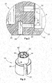
Figur 2 eine vergrößerte Darstellung eines Schmiermittel-Versorgungskanals in dem Gehäuse der Kfz-Vakuumpumpe derFigur 1 , -
Figur 3 eine perspektivische Ansicht des Pumpenrotors der Kfz-Vakuumpumpe derFigur 1 , -
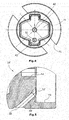
Figur 4 eine Draufsicht auf die dem Steckkupplungs-Element zugewandte Seite des Pumpenrotors, und -
Figur 5 eine zweite Ausführungsform eines stationären Schmiermittel-Versorgungskanals. - In der
Figur 1 ist schematisch eine Vakuumpumpen-Anordnung dargestellt, die im wesentlichen aus einer mechanischen Kfz-Vakuumpumpe 10, einem Verbrennungsmotor 52 und einer dem Verbrennungsmotor 52 zugeordneten Schmiermittelpumpe 54 besteht. Die Vakuumpumpe 10 ist mechanisch über eine Steckkupplungs-Anordnung 68 mit einer Kurbelwelle oder einer Antriebswelle des Verbrennungsmotors 52 rotatorisch gekoppelt. Die Vakuumpumpe 10 dient beispielsweise dazu, für verschiedene Nebenaggregate des Kraftfahrzeugs aktuatorisches Vakuum zur Verfügung zu stellen, beispielsweise für einen pneumatischen Bremskraftverstärker. Die Schmiermittelpumpe 54 fördert das flüssige Schmiermittel für die Schmiermittelversorgung des Verbrennungsmotors 52 und die Schmiermittelversorgung der Vakuumpumpe 10. - Die Vakuumpumpe 10 ist eine sogenannte Flügelzellenpumpe und weist ein Pumpengehäuse 14 auf, das im Wesentlichen von einem massiven Gehäusekörper 13 und einem Gehäusedeckel 19 gebildet wird. In dem Pumpengehäuse 14 ist ein um eine Längsachse drehbar gelagerter Pumpenrotor 16 angeordnet. Das Pumpenrotor-Gleitlager wird von einer gehäuseseitigen Hohlzylinderfläche 71 und einer korrespondierenden rotorseitigen Aufienzylinderfläche 72 gebildet. Der Pumpenrotor 16 weist einen Rotorkörper 17 mit einem radialen Flügelschlitz 21 auf, in dem ein Rotorflügel 18 radial verschiebbar gelagert ist. Der Rotorflügel 18 rotiert in einem von dem Pumpengehäuse 14 definierten Pumpenraum 12 und fördert auf diese Weise Luft von einem nicht dargestellten Pumpeneinlass zu einem nicht dargestellten Pumpenauslass.
- Die Steckkupplungs-Anordnung 68 wird von zwei Steckkupplungs-Elementen 20,50 gebildet, die drehfest ineinander greifen, jedoch eine axiale und radiale Bewegung der beiden Steckkupplungs-Elemente 20,50 zueinander zulassen. Das pumpenseitige Steckkupplungs-Element 20 ist über eine komplexe Formschlussstruktur 60 seinerseits drehfest von dem Pumpenrotor 16 gehalten. Die Formschlussstruktur 60 erlaubt ebenfalls eine axiale und radiale Beweglichkeit des pumpenseitigen Steckkupplungs-Elements 20 im Verhältnis zu dem Pumpenrotor 16.
- Das pumpenseitige Steckkupplungs-Element 20 weist eine durchgehende Zentralbohrung 74 auf, durch die ein Haltebolzen 70 gesteckt ist, der mit Klemmsitz fest in einem zentralen Sackloch 42 des Pumpenrotors 16 fixiert ist. Die Zentralbohrung 74 weist einen Innendurchmesser auf, der geringfügig größer als der Außendurchmesser des Haltebolzens 70 ist, so dass eine gewisse radiale Beweglichkeit des Steckkupplungs-Elements 20 gegenüber dem Pumpenrotor 16 zugelassen wird. Die Länge des Steckbolzen-Schaftabschnittes, der aus dem Sackloch 42 axial herausragt, ist geringfügig größer als die Länge der axialen Zentralbohrung 74, so dass auch eine gewisse axiale Beweglichkeit des Steckkupplungs-Elements 20 im Bezug auf den Pumpenrotor 16 gewährleistet ist.
- Der Pumpenrotor 16 weist eine hohlkreuzartige Formschlussstruktur 60 auf, die in der
Figur 1 nur schematisch dargestellt ist und denFiguren 3 und4 detaillierter entnommen werden kann. Die Formschlussstruktur 60 weist eine in einer Querebene liegende Bodenwand 34 auf und ist umgeben von einer Seitenwand 40, die die hohlkreuzartige Formschlussstruktur 60 definiert. Das Steckkupplungs-Element 20 weist an seiner dem Pumpenrotor 16 zugewandten Seite eine zu der hohlkreuzartigen Formschlussstruktur annähernd komplementäre kreuzartige Formschlussstruktur auf, die eine drehfeste Kopplung des Steckkupplungs-Elements 20 mit dem Pumpenrotor 16 herstellt. Das Steckkupplungs-Element 20 weist eine Stirnwand 36 auf, die ebenfalls in einer Querebene liegt und an die pumpenrotorseitige Bodenwand 34 parallel angrenzt. Zwischen der Formschlussstruktur-Seitenwand 40 und der Umfangswand 38 des Steckkupplungs-Elements 20 ist ein radialer Spalt vorgesehen, durch den eine gewisse radiale Beweglichkeit des Steckkupplungs-Elements 20 im Verhältnis zu dem Pumpenrotor 16 zugelassen wird. Das Steckkupplungs-Element 20 weist auf seiner distalen Seite mehrere axiale Klauen 44 auf, die mit korrespondierenden Klauen des motorseitigen Steckkupplungs-Elements 50 ineinander greifen. - Das Pumpengehäuse 14 bzw. der Gehäusekörper 13 weist einen Schmiermittel-Versorgungskanal 22 auf, durch den von einem gehäuseseitigen Schmiermittel-Einlass 24 das über eine Leitung 56 von der Schmiermittelpumpe 54 unter Druck kommende flüssige Schmiermittel zu einer Übergabeöffnung 26 geleitet wird, die in der Hohlzylinderfläche 71 des Rotor-Gleitlagers liegt. Der Pumpenrotor 16 weist einen Schmiermittel-Transportkanal 30 auf, durch den das Schmiermittel von einer Übernahmeöffnung 28 zu einer Schmiermittel-Auslassöffnung 32 geleitet wird. Die Übernahmeöffnung 28 liegt in der Gleitlager-Außenzylinderfläche 72 und ist derart angeordnet, dass die Übernahmeöffnung 28 während jeder vollen Umdrehung des Pumpenrotors 16 einmal mit der Übergabeöffnung 26 fluchtet, so dass auf diese Weise eine intermittierender Schmiermittel-Strom realisiert wird. Die Schmiermittel-Auslassöffnung 32 liegt in der Bodenwand 34 der Formschlussstruktur 60, wobei die Stirnwand 36 des Steckkupplungs-Elements 20 die Auslassöffnung 32 verdeckt, jedoch durch den Fluiddruck des austretenden Schmiermittels in einem kleinen axialen Abstand gehalten wird.
- Wie in der
Figur 2 gut erkennbar ist, ist die Auslassöffnung 32 exzentrisch zu der Rotationsachse des Pumpenrotors 16 angeordnet. Die Exzentrizität E der Schmiermittel-Auslassöffnung 32 beträgt vorliegend mehr als 3/4 des Radius R der Steckkupplungs-Stirnwand 36. Der Transportkanal 30 ist rechtwinklig in dem Gehäusekörper 13 ausgebildet. In einer zweiten Ausführungsform des Pumpenrotors 16', die in derFigur 5 dargestellt ist, ist der Transportkanal 30', der in der Schmiermittel-Auslassöffnung 32' mündet, schräg und geradlinig ausgebildet. Bei dieser Ausführungsform ist die Herstellung des Transportkanals 30 vereinfacht, da zu seiner Herstellung nur ein einziger Bohrvorgang erforderlich ist.
Claims (5)
- Mechanische Kfz- Vakuumpumpe (10) mit einem in einem stationären Pumpengehäuse (14) drehbar gelagerten Pumpenrotor (16) und einem separaten pumpenseitigen Steckkupplungs-Element (20), das drehfest mit dem Pumpenrotor (16) verbunden ist, wobei eine Schmiermittelversorgung zum Schmieren des Steckkupplungs-Elements (20) vorgesehen ist, die aufweist:einen stationären Schmiermittel- Versorgungskanal (22) in dem Pumpengehäuse (14), durch den das Schmiermittel von einem Schmiermittel-Einlass (24) des Pumpengehäuses (14) in Richtung Kupplungsanordnung (20) zu einer Übergabeöffnung (26) gepumpt wird, undeinen Schmiermittel-Transportkanal (30; 30') in dem Pumpenrotor (16; 16'), wobei durch den Transportkanal (30; 30') das Schmiermittel von einer Übernahmeöffnung (28) zu einer Schmiermittel-Auslassöffnung (32) gepumpt wird,wobei die Übergabeöffnung (26) und die Übernahmeöffnung (28) derart angeordnet sind, dass sie während einer Rotorumdrehung des Pumpenrotors (16) mindestens vorübergehend fluidisch miteinander verbunden sind, undwobei die Auslassöffnung (32) exzentrisch in einer Stirnwand (34) des Pumpenrotors (16) angeordnet ist.
- Mechanische Kfz-Vakuumpumpe (10) nach Anspruch 1, wobei die Exzentrizität (E) der Auslassöffnung (32) größer als der halbe Radius (R) der Steckkupplungs-Stirnwand (36) ist.
- Mechanische Kfz-Vakuumpumpe (10) nach einem der vorangegangenen Ansprüche, wobei die Pumpenrotor-Stirnwand (34) und die Steckkupplungs--Stirnwand (36) in einer gemeinsamen Querebene liegen.
- Mechanische Kfz-Vakuumpumpe (10) nach einem der vorangegangenen Ansprüche, wobei Übergabeöffnung (26) und die Übernahmeöffnung (28) in einer gemeinsamen Zylinderfläche liegen.
- Mechanische Kfz-Vakuumpumpe (10) nach einem der vorangegangenen Ansprüche, wobei das Steckkupplungs-Element (20) durch einen Haltebolzen (70) an dem Pumpenrotor (16) gehalten ist, wobei der Haltebolzen (70) in einem Sackloch (42) des Pumpenrotors (16) fixiert ist.
Priority Applications (5)
| Application Number | Priority Date | Filing Date | Title |
|---|---|---|---|
| EP14197706.6A EP3032105B1 (de) | 2014-12-12 | 2014-12-12 | Mechanische kfz-vakuumpumpe |
| PCT/EP2015/079064 WO2016091922A1 (de) | 2014-12-12 | 2015-12-09 | Mechanische kfz-vakuumpumpe |
| JP2017516707A JP6317527B2 (ja) | 2014-12-12 | 2015-12-09 | 自動車用機械式真空ポンプ |
| CN201580056729.3A CN107002682B (zh) | 2014-12-12 | 2015-12-09 | 用于机动车的机械式真空泵 |
| US15/534,004 US10443599B2 (en) | 2014-12-12 | 2015-12-09 | Mechanical vacuum pump for a motor vehicle |
Applications Claiming Priority (1)
| Application Number | Priority Date | Filing Date | Title |
|---|---|---|---|
| EP14197706.6A EP3032105B1 (de) | 2014-12-12 | 2014-12-12 | Mechanische kfz-vakuumpumpe |
Publications (2)
| Publication Number | Publication Date |
|---|---|
| EP3032105A1 true EP3032105A1 (de) | 2016-06-15 |
| EP3032105B1 EP3032105B1 (de) | 2021-05-19 |
Family
ID=52021129
Family Applications (1)
| Application Number | Title | Priority Date | Filing Date |
|---|---|---|---|
| EP14197706.6A Active EP3032105B1 (de) | 2014-12-12 | 2014-12-12 | Mechanische kfz-vakuumpumpe |
Country Status (5)
| Country | Link |
|---|---|
| US (1) | US10443599B2 (de) |
| EP (1) | EP3032105B1 (de) |
| JP (1) | JP6317527B2 (de) |
| CN (1) | CN107002682B (de) |
| WO (1) | WO2016091922A1 (de) |
Cited By (1)
| Publication number | Priority date | Publication date | Assignee | Title |
|---|---|---|---|---|
| WO2018010793A1 (de) * | 2016-07-14 | 2018-01-18 | Pierburg Pump Technology Gmbh | Kfz-vakuumpumpe |
Families Citing this family (1)
| Publication number | Priority date | Publication date | Assignee | Title |
|---|---|---|---|---|
| US11639720B2 (en) | 2017-01-30 | 2023-05-02 | Litens Automotive Partnership | Clutched vacuum pump system |
Citations (5)
| Publication number | Priority date | Publication date | Assignee | Title |
|---|---|---|---|---|
| US2148070A (en) * | 1937-04-29 | 1939-02-21 | Eclipse Aviat Corp | Pump |
| JPS58133495A (ja) * | 1982-02-02 | 1983-08-09 | Matsushita Electric Ind Co Ltd | ベ−ン回転式圧縮機の油供給装置 |
| WO2009046810A1 (de) * | 2007-10-02 | 2009-04-16 | Ixetic Hückeswagen Gmbh | Vakuumpumpe, insbesondere flügelzellenpumpe |
| EP2559903A1 (de) * | 2011-08-17 | 2013-02-20 | Wabco Automotive UK Limited | Verbesserte Vakuumpumpe |
| WO2014063681A1 (de) | 2012-10-22 | 2014-05-01 | Ixetic Bad Homburg Gmbh | Intermittierende kupplungsbeölung |
Family Cites Families (7)
| Publication number | Priority date | Publication date | Assignee | Title |
|---|---|---|---|---|
| US6923628B1 (en) * | 1998-09-30 | 2005-08-02 | Luk, Automobitechnik Gmbh | Vacuum pump |
| DE19961317C1 (de) | 1999-12-18 | 2001-06-28 | Bayerische Motoren Werke Ag | Vakuumpumpe, insbesondere Flügelzellenvakuumpumpe |
| KR100427567B1 (ko) * | 2001-04-12 | 2004-04-17 | 주식회사 우성진공 | 로터리 베인형 진공펌프의 로터 |
| JP2004092504A (ja) | 2002-08-30 | 2004-03-25 | Toyoda Mach Works Ltd | ベーン式バキュームポンプ |
| EP1886025B1 (de) * | 2005-05-19 | 2012-03-07 | ixetic Hückeswagen GmbH | Flügelzellenpumpe |
| JP5589532B2 (ja) | 2010-04-27 | 2014-09-17 | 大豊工業株式会社 | ベーンポンプ |
| CN102959708B (zh) | 2010-06-29 | 2016-05-04 | 柯立芝照明有限公司 | 具有易弯曲基板的电子装置 |
-
2014
- 2014-12-12 EP EP14197706.6A patent/EP3032105B1/de active Active
-
2015
- 2015-12-09 WO PCT/EP2015/079064 patent/WO2016091922A1/de not_active Ceased
- 2015-12-09 JP JP2017516707A patent/JP6317527B2/ja not_active Expired - Fee Related
- 2015-12-09 CN CN201580056729.3A patent/CN107002682B/zh not_active Expired - Fee Related
- 2015-12-09 US US15/534,004 patent/US10443599B2/en active Active
Patent Citations (5)
| Publication number | Priority date | Publication date | Assignee | Title |
|---|---|---|---|---|
| US2148070A (en) * | 1937-04-29 | 1939-02-21 | Eclipse Aviat Corp | Pump |
| JPS58133495A (ja) * | 1982-02-02 | 1983-08-09 | Matsushita Electric Ind Co Ltd | ベ−ン回転式圧縮機の油供給装置 |
| WO2009046810A1 (de) * | 2007-10-02 | 2009-04-16 | Ixetic Hückeswagen Gmbh | Vakuumpumpe, insbesondere flügelzellenpumpe |
| EP2559903A1 (de) * | 2011-08-17 | 2013-02-20 | Wabco Automotive UK Limited | Verbesserte Vakuumpumpe |
| WO2014063681A1 (de) | 2012-10-22 | 2014-05-01 | Ixetic Bad Homburg Gmbh | Intermittierende kupplungsbeölung |
Cited By (1)
| Publication number | Priority date | Publication date | Assignee | Title |
|---|---|---|---|---|
| WO2018010793A1 (de) * | 2016-07-14 | 2018-01-18 | Pierburg Pump Technology Gmbh | Kfz-vakuumpumpe |
Also Published As
| Publication number | Publication date |
|---|---|
| CN107002682B (zh) | 2019-08-20 |
| JP6317527B2 (ja) | 2018-04-25 |
| CN107002682A (zh) | 2017-08-01 |
| WO2016091922A1 (de) | 2016-06-16 |
| US20180335035A1 (en) | 2018-11-22 |
| JP2017532490A (ja) | 2017-11-02 |
| US10443599B2 (en) | 2019-10-15 |
| EP3032105B1 (de) | 2021-05-19 |
Similar Documents
| Publication | Publication Date | Title |
|---|---|---|
| EP2469048B1 (de) | Nockenwellenversteller | |
| EP2815127B1 (de) | Drehkolbenpumpe | |
| EP1477636A2 (de) | Nockenwellenversteller für Verbrennungskraftmaschinen | |
| DE102016121241B4 (de) | Hydraulischer Antrieb, hydraulischer Motor und integrierte Pumpe mit dem hydraulischen Antrieb | |
| EP2313656A2 (de) | Pumpeneinheit | |
| EP3503356A1 (de) | Kühlmittelverteiler für eine maschinenanordnung sowie entsprechende maschinenanordnung | |
| DE102014222321B3 (de) | Flügelzellenpumpe mit verbessertem Startverhalten | |
| DE102012103888A1 (de) | Verdrängerpumpe | |
| EP3032105B1 (de) | Mechanische kfz-vakuumpumpe | |
| DE102009037443A1 (de) | Selbstansaugende Flügelzellenpumpe | |
| EP3015708B1 (de) | Flügelzellenpumpe mit verbessertem startverhalten | |
| EP3827170B1 (de) | Fluidfördereinrichtung | |
| EP2707629B1 (de) | Vorrichtung zum abdichten eines pumpraums einer drehkolbenpumpe, sowie drehkolbenpumpe mit selbiger | |
| DE102014208775A1 (de) | Gasflügelpumpe und Verfahren zum Betrieb der Gasflügelpumpe | |
| DE102009017452B4 (de) | Ölförderpumpe | |
| EP0515929A1 (de) | Flügelzellenvakuumpumpe | |
| DE102012208495B4 (de) | Nockenwellenversteller | |
| DE102021133447A1 (de) | Magnetkupplungspumpenanordnung | |
| WO2017021117A1 (de) | Verdrängerpumpe zur förderung eines fluides für einen verbraucher eines kraftfahrzeuges | |
| EP4259935B1 (de) | Pumpenvorrichtung für ein hydraulisches system eines kraftfahrzeugs, hydraulisches system | |
| EP4166752B1 (de) | Pumpe mit axialsicherung | |
| WO2013087235A1 (de) | Aktuatoranordnung zur betätigung einer kupplungsvorrichtung | |
| EP3574215A1 (de) | Pumpenvorrichtung | |
| WO2018010793A1 (de) | Kfz-vakuumpumpe | |
| EP3819481A1 (de) | Nockenwellen-anordnung |
Legal Events
| Date | Code | Title | Description |
|---|---|---|---|
| PUAI | Public reference made under article 153(3) epc to a published international application that has entered the european phase |
Free format text: ORIGINAL CODE: 0009012 |
|
| AK | Designated contracting states |
Kind code of ref document: A1 Designated state(s): AL AT BE BG CH CY CZ DE DK EE ES FI FR GB GR HR HU IE IS IT LI LT LU LV MC MK MT NL NO PL PT RO RS SE SI SK SM TR |
|
| AX | Request for extension of the european patent |
Extension state: BA ME |
|
| STAA | Information on the status of an ep patent application or granted ep patent |
Free format text: STATUS: REQUEST FOR EXAMINATION WAS MADE |
|
| 17P | Request for examination filed |
Effective date: 20161209 |
|
| RBV | Designated contracting states (corrected) |
Designated state(s): AL AT BE BG CH CY CZ DE DK EE ES FI FR GB GR HR HU IE IS IT LI LT LU LV MC MK MT NL NO PL PT RO RS SE SI SK SM TR |
|
| STAA | Information on the status of an ep patent application or granted ep patent |
Free format text: STATUS: EXAMINATION IS IN PROGRESS |
|
| 17Q | First examination report despatched |
Effective date: 20200206 |
|
| GRAP | Despatch of communication of intention to grant a patent |
Free format text: ORIGINAL CODE: EPIDOSNIGR1 |
|
| STAA | Information on the status of an ep patent application or granted ep patent |
Free format text: STATUS: GRANT OF PATENT IS INTENDED |
|
| INTG | Intention to grant announced |
Effective date: 20201218 |
|
| GRAS | Grant fee paid |
Free format text: ORIGINAL CODE: EPIDOSNIGR3 |
|
| GRAA | (expected) grant |
Free format text: ORIGINAL CODE: 0009210 |
|
| STAA | Information on the status of an ep patent application or granted ep patent |
Free format text: STATUS: THE PATENT HAS BEEN GRANTED |
|
| AK | Designated contracting states |
Kind code of ref document: B1 Designated state(s): AL AT BE BG CH CY CZ DE DK EE ES FI FR GB GR HR HU IE IS IT LI LT LU LV MC MK MT NL NO PL PT RO RS SE SI SK SM TR |
|
| REG | Reference to a national code |
Ref country code: GB Ref legal event code: FG4D Free format text: NOT ENGLISH |
|
| REG | Reference to a national code |
Ref country code: CH Ref legal event code: EP |
|
| REG | Reference to a national code |
Ref country code: DE Ref legal event code: R096 Ref document number: 502014015586 Country of ref document: DE |
|
| REG | Reference to a national code |
Ref country code: AT Ref legal event code: REF Ref document number: 1394236 Country of ref document: AT Kind code of ref document: T Effective date: 20210615 |
|
| REG | Reference to a national code |
Ref country code: IE Ref legal event code: FG4D Free format text: LANGUAGE OF EP DOCUMENT: GERMAN |
|
| REG | Reference to a national code |
Ref country code: LT Ref legal event code: MG9D |
|
| REG | Reference to a national code |
Ref country code: NL Ref legal event code: MP Effective date: 20210519 |
|
| PG25 | Lapsed in a contracting state [announced via postgrant information from national office to epo] |
Ref country code: HR Free format text: LAPSE BECAUSE OF FAILURE TO SUBMIT A TRANSLATION OF THE DESCRIPTION OR TO PAY THE FEE WITHIN THE PRESCRIBED TIME-LIMIT Effective date: 20210519 Ref country code: BG Free format text: LAPSE BECAUSE OF FAILURE TO SUBMIT A TRANSLATION OF THE DESCRIPTION OR TO PAY THE FEE WITHIN THE PRESCRIBED TIME-LIMIT Effective date: 20210819 Ref country code: LT Free format text: LAPSE BECAUSE OF FAILURE TO SUBMIT A TRANSLATION OF THE DESCRIPTION OR TO PAY THE FEE WITHIN THE PRESCRIBED TIME-LIMIT Effective date: 20210519 Ref country code: FI Free format text: LAPSE BECAUSE OF FAILURE TO SUBMIT A TRANSLATION OF THE DESCRIPTION OR TO PAY THE FEE WITHIN THE PRESCRIBED TIME-LIMIT Effective date: 20210519 |
|
| PG25 | Lapsed in a contracting state [announced via postgrant information from national office to epo] |
Ref country code: LV Free format text: LAPSE BECAUSE OF FAILURE TO SUBMIT A TRANSLATION OF THE DESCRIPTION OR TO PAY THE FEE WITHIN THE PRESCRIBED TIME-LIMIT Effective date: 20210519 Ref country code: IS Free format text: LAPSE BECAUSE OF FAILURE TO SUBMIT A TRANSLATION OF THE DESCRIPTION OR TO PAY THE FEE WITHIN THE PRESCRIBED TIME-LIMIT Effective date: 20210919 Ref country code: GR Free format text: LAPSE BECAUSE OF FAILURE TO SUBMIT A TRANSLATION OF THE DESCRIPTION OR TO PAY THE FEE WITHIN THE PRESCRIBED TIME-LIMIT Effective date: 20210820 Ref country code: SE Free format text: LAPSE BECAUSE OF FAILURE TO SUBMIT A TRANSLATION OF THE DESCRIPTION OR TO PAY THE FEE WITHIN THE PRESCRIBED TIME-LIMIT Effective date: 20210519 Ref country code: RS Free format text: LAPSE BECAUSE OF FAILURE TO SUBMIT A TRANSLATION OF THE DESCRIPTION OR TO PAY THE FEE WITHIN THE PRESCRIBED TIME-LIMIT Effective date: 20210519 Ref country code: PL Free format text: LAPSE BECAUSE OF FAILURE TO SUBMIT A TRANSLATION OF THE DESCRIPTION OR TO PAY THE FEE WITHIN THE PRESCRIBED TIME-LIMIT Effective date: 20210519 Ref country code: NO Free format text: LAPSE BECAUSE OF FAILURE TO SUBMIT A TRANSLATION OF THE DESCRIPTION OR TO PAY THE FEE WITHIN THE PRESCRIBED TIME-LIMIT Effective date: 20210819 Ref country code: PT Free format text: LAPSE BECAUSE OF FAILURE TO SUBMIT A TRANSLATION OF THE DESCRIPTION OR TO PAY THE FEE WITHIN THE PRESCRIBED TIME-LIMIT Effective date: 20210920 Ref country code: ES Free format text: LAPSE BECAUSE OF FAILURE TO SUBMIT A TRANSLATION OF THE DESCRIPTION OR TO PAY THE FEE WITHIN THE PRESCRIBED TIME-LIMIT Effective date: 20210519 |
|
| PG25 | Lapsed in a contracting state [announced via postgrant information from national office to epo] |
Ref country code: NL Free format text: LAPSE BECAUSE OF FAILURE TO SUBMIT A TRANSLATION OF THE DESCRIPTION OR TO PAY THE FEE WITHIN THE PRESCRIBED TIME-LIMIT Effective date: 20210519 |
|
| PG25 | Lapsed in a contracting state [announced via postgrant information from national office to epo] |
Ref country code: SM Free format text: LAPSE BECAUSE OF FAILURE TO SUBMIT A TRANSLATION OF THE DESCRIPTION OR TO PAY THE FEE WITHIN THE PRESCRIBED TIME-LIMIT Effective date: 20210519 Ref country code: SK Free format text: LAPSE BECAUSE OF FAILURE TO SUBMIT A TRANSLATION OF THE DESCRIPTION OR TO PAY THE FEE WITHIN THE PRESCRIBED TIME-LIMIT Effective date: 20210519 Ref country code: EE Free format text: LAPSE BECAUSE OF FAILURE TO SUBMIT A TRANSLATION OF THE DESCRIPTION OR TO PAY THE FEE WITHIN THE PRESCRIBED TIME-LIMIT Effective date: 20210519 Ref country code: CZ Free format text: LAPSE BECAUSE OF FAILURE TO SUBMIT A TRANSLATION OF THE DESCRIPTION OR TO PAY THE FEE WITHIN THE PRESCRIBED TIME-LIMIT Effective date: 20210519 Ref country code: DK Free format text: LAPSE BECAUSE OF FAILURE TO SUBMIT A TRANSLATION OF THE DESCRIPTION OR TO PAY THE FEE WITHIN THE PRESCRIBED TIME-LIMIT Effective date: 20210519 Ref country code: RO Free format text: LAPSE BECAUSE OF FAILURE TO SUBMIT A TRANSLATION OF THE DESCRIPTION OR TO PAY THE FEE WITHIN THE PRESCRIBED TIME-LIMIT Effective date: 20210519 |
|
| REG | Reference to a national code |
Ref country code: DE Ref legal event code: R097 Ref document number: 502014015586 Country of ref document: DE |
|
| PLBE | No opposition filed within time limit |
Free format text: ORIGINAL CODE: 0009261 |
|
| STAA | Information on the status of an ep patent application or granted ep patent |
Free format text: STATUS: NO OPPOSITION FILED WITHIN TIME LIMIT |
|
| 26N | No opposition filed |
Effective date: 20220222 |
|
| PG25 | Lapsed in a contracting state [announced via postgrant information from national office to epo] |
Ref country code: IS Free format text: LAPSE BECAUSE OF FAILURE TO SUBMIT A TRANSLATION OF THE DESCRIPTION OR TO PAY THE FEE WITHIN THE PRESCRIBED TIME-LIMIT Effective date: 20210919 Ref country code: AL Free format text: LAPSE BECAUSE OF FAILURE TO SUBMIT A TRANSLATION OF THE DESCRIPTION OR TO PAY THE FEE WITHIN THE PRESCRIBED TIME-LIMIT Effective date: 20210519 |
|
| PG25 | Lapsed in a contracting state [announced via postgrant information from national office to epo] |
Ref country code: MC Free format text: LAPSE BECAUSE OF FAILURE TO SUBMIT A TRANSLATION OF THE DESCRIPTION OR TO PAY THE FEE WITHIN THE PRESCRIBED TIME-LIMIT Effective date: 20210519 |
|
| REG | Reference to a national code |
Ref country code: CH Ref legal event code: PL |
|
| GBPC | Gb: european patent ceased through non-payment of renewal fee |
Effective date: 20211212 |
|
| REG | Reference to a national code |
Ref country code: BE Ref legal event code: MM Effective date: 20211231 |
|
| PG25 | Lapsed in a contracting state [announced via postgrant information from national office to epo] |
Ref country code: LU Free format text: LAPSE BECAUSE OF NON-PAYMENT OF DUE FEES Effective date: 20211212 Ref country code: IE Free format text: LAPSE BECAUSE OF NON-PAYMENT OF DUE FEES Effective date: 20211212 Ref country code: GB Free format text: LAPSE BECAUSE OF NON-PAYMENT OF DUE FEES Effective date: 20211212 |
|
| PG25 | Lapsed in a contracting state [announced via postgrant information from national office to epo] |
Ref country code: BE Free format text: LAPSE BECAUSE OF NON-PAYMENT OF DUE FEES Effective date: 20211231 |
|
| PG25 | Lapsed in a contracting state [announced via postgrant information from national office to epo] |
Ref country code: LI Free format text: LAPSE BECAUSE OF NON-PAYMENT OF DUE FEES Effective date: 20211231 Ref country code: CH Free format text: LAPSE BECAUSE OF NON-PAYMENT OF DUE FEES Effective date: 20211231 |
|
| REG | Reference to a national code |
Ref country code: AT Ref legal event code: MM01 Ref document number: 1394236 Country of ref document: AT Kind code of ref document: T Effective date: 20211212 |
|
| PG25 | Lapsed in a contracting state [announced via postgrant information from national office to epo] |
Ref country code: AT Free format text: LAPSE BECAUSE OF NON-PAYMENT OF DUE FEES Effective date: 20211212 |
|
| PG25 | Lapsed in a contracting state [announced via postgrant information from national office to epo] |
Ref country code: HU Free format text: LAPSE BECAUSE OF FAILURE TO SUBMIT A TRANSLATION OF THE DESCRIPTION OR TO PAY THE FEE WITHIN THE PRESCRIBED TIME-LIMIT; INVALID AB INITIO Effective date: 20141212 |
|
| PG25 | Lapsed in a contracting state [announced via postgrant information from national office to epo] |
Ref country code: CY Free format text: LAPSE BECAUSE OF FAILURE TO SUBMIT A TRANSLATION OF THE DESCRIPTION OR TO PAY THE FEE WITHIN THE PRESCRIBED TIME-LIMIT Effective date: 20210519 |
|
| PGFP | Annual fee paid to national office [announced via postgrant information from national office to epo] |
Ref country code: FR Payment date: 20231220 Year of fee payment: 10 |
|
| PG25 | Lapsed in a contracting state [announced via postgrant information from national office to epo] |
Ref country code: MK Free format text: LAPSE BECAUSE OF FAILURE TO SUBMIT A TRANSLATION OF THE DESCRIPTION OR TO PAY THE FEE WITHIN THE PRESCRIBED TIME-LIMIT Effective date: 20210519 |
|
| PGFP | Annual fee paid to national office [announced via postgrant information from national office to epo] |
Ref country code: IT Payment date: 20231229 Year of fee payment: 10 |
|
| PG25 | Lapsed in a contracting state [announced via postgrant information from national office to epo] |
Ref country code: MT Free format text: LAPSE BECAUSE OF FAILURE TO SUBMIT A TRANSLATION OF THE DESCRIPTION OR TO PAY THE FEE WITHIN THE PRESCRIBED TIME-LIMIT Effective date: 20210519 |
|
| PG25 | Lapsed in a contracting state [announced via postgrant information from national office to epo] |
Ref country code: IT Free format text: LAPSE BECAUSE OF NON-PAYMENT OF DUE FEES Effective date: 20241212 |
|
| PG25 | Lapsed in a contracting state [announced via postgrant information from national office to epo] |
Ref country code: FR Free format text: LAPSE BECAUSE OF NON-PAYMENT OF DUE FEES Effective date: 20241231 |
|
| PG25 | Lapsed in a contracting state [announced via postgrant information from national office to epo] |
Ref country code: TR Free format text: LAPSE BECAUSE OF FAILURE TO SUBMIT A TRANSLATION OF THE DESCRIPTION OR TO PAY THE FEE WITHIN THE PRESCRIBED TIME-LIMIT Effective date: 20210519 |
|
| PGFP | Annual fee paid to national office [announced via postgrant information from national office to epo] |
Ref country code: DE Payment date: 20251211 Year of fee payment: 12 |
|
| REG | Reference to a national code |
Ref country code: DE Ref legal event code: R082 Ref document number: 502014015586 Country of ref document: DE |