EP3032107A2 - Pompe turbomoleculaire - Google Patents
Pompe turbomoleculaire Download PDFInfo
- Publication number
- EP3032107A2 EP3032107A2 EP15191438.9A EP15191438A EP3032107A2 EP 3032107 A2 EP3032107 A2 EP 3032107A2 EP 15191438 A EP15191438 A EP 15191438A EP 3032107 A2 EP3032107 A2 EP 3032107A2
- Authority
- EP
- European Patent Office
- Prior art keywords
- rotor
- pump
- stator
- turbomolecular
- blade
- Prior art date
- Legal status (The legal status is an assumption and is not a legal conclusion. Google has not performed a legal analysis and makes no representation as to the accuracy of the status listed.)
- Granted
Links
Images


Classifications
-
- F—MECHANICAL ENGINEERING; LIGHTING; HEATING; WEAPONS; BLASTING
- F04—POSITIVE - DISPLACEMENT MACHINES FOR LIQUIDS; PUMPS FOR LIQUIDS OR ELASTIC FLUIDS
- F04D—NON-POSITIVE-DISPLACEMENT PUMPS
- F04D19/00—Axial-flow pumps
- F04D19/02—Multi-stage pumps
- F04D19/04—Multi-stage pumps specially adapted to the production of a high vacuum, e.g. molecular pumps
- F04D19/042—Turbomolecular vacuum pumps
-
- F—MECHANICAL ENGINEERING; LIGHTING; HEATING; WEAPONS; BLASTING
- F04—POSITIVE - DISPLACEMENT MACHINES FOR LIQUIDS; PUMPS FOR LIQUIDS OR ELASTIC FLUIDS
- F04D—NON-POSITIVE-DISPLACEMENT PUMPS
- F04D19/00—Axial-flow pumps
- F04D19/02—Multi-stage pumps
- F04D19/04—Multi-stage pumps specially adapted to the production of a high vacuum, e.g. molecular pumps
- F04D19/044—Holweck-type pumps
-
- F—MECHANICAL ENGINEERING; LIGHTING; HEATING; WEAPONS; BLASTING
- F04—POSITIVE - DISPLACEMENT MACHINES FOR LIQUIDS; PUMPS FOR LIQUIDS OR ELASTIC FLUIDS
- F04D—NON-POSITIVE-DISPLACEMENT PUMPS
- F04D29/00—Details, component parts, or accessories
- F04D29/40—Casings; Connections of working fluid
- F04D29/52—Casings; Connections of working fluid for axial pumps
- F04D29/522—Casings; Connections of working fluid for axial pumps especially adapted for elastic fluid pumps
- F04D29/526—Details of the casing section radially opposing blade tips
-
- F—MECHANICAL ENGINEERING; LIGHTING; HEATING; WEAPONS; BLASTING
- F04—POSITIVE - DISPLACEMENT MACHINES FOR LIQUIDS; PUMPS FOR LIQUIDS OR ELASTIC FLUIDS
- F04D—NON-POSITIVE-DISPLACEMENT PUMPS
- F04D29/00—Details, component parts, or accessories
- F04D29/66—Combating cavitation, whirls, noise, vibration or the like; Balancing
- F04D29/68—Combating cavitation, whirls, noise, vibration or the like; Balancing by influencing boundary layers
- F04D29/681—Combating cavitation, whirls, noise, vibration or the like; Balancing by influencing boundary layers especially adapted for elastic fluid pumps
- F04D29/685—Inducing localised fluid recirculation in the stator-rotor interface
Definitions
- the invention relates to a turbomolecular pump having at least one turbomolecular pump stage, which comprises at least one blade rotor rotatably mounted about an axis.
- turbomolecular pumps are basically known and are known e.g. used in the semiconductor industry and in physical research to generate a high vacuum needed there.
- the turbomolecular pump is characterized by a blade rotor, also referred to below as a rotor, whose structure is reminiscent of the rotor of a turbine.
- the blade rotor interacts with a blade stator, also referred to below as a stator, and usually rotates at such a high speed that the tangential velocity of the individual rotor blades is of a similar magnitude to the mean thermal velocity of particles to be conveyed.
- a vertical pumping direction from top to bottom, the majority of the particles collide with a bottom surface of an angularly pitched rotor blade.
- By a preferred direction of the bottom of the rotor blade in the pumping direction creates a pumping action.
- the rotor must also be surrounded by a wall to prevent backflow of the particles outside the rotor area.
- a wall is formed, for example, from the inside of a housing containing the turbomolecular pumping stage or from the insides of stator stator rings arranged between individual stator disks.
- This wall has a cylindrical inner surface, which is arranged concentrically to the rotor and whose preferred direction points radially inward and thus in the pumping direction. Particles that by themselves or after colliding with a rotor blade on the cylindrical inner surface of the wall meet there no pumping action more.
- a turbomolecular pump with the features of claim 1, and in particular in that a wall at least partially surrounding the blade rotor is provided on at least one pump effective portion of its blade rotor side facing with at least one recess.
- the performance of the turbomolecular pump can be improved by giving particles which hit the wall a preferred direction in the pumping direction.
- a such depression can be easily introduced, for example, with an ordinary milling tool.
- turbomolecular pump enables the technical adaptation of a static component of the turbomolecular pump. Static components are not exposed to such high mechanical loads as rotor components. They can therefore be modified and installed without qualification. For this reason, further developments of turbomolecular pumps are particularly advantageous in terms of development if they merely relate to static components, as is possible according to the invention here.
- the pumping action is further improved if the depression has a course with an axial component and / or with a non-zero pitch. As a result, the particles are given a preferential direction, likewise with an axial component. The pumping action in the axial direction is thus improved.
- the recess may have a spiral or helical course.
- the recess may thus have a thread profile corresponding to the recess profile in Gaede'sche screw pumps or molecular pumps according to Holweck.
- the depression may be formed as a helix. As a result, the particles are taught even more uniformly the desired preferred direction.
- the spiral or helical course of the depression advantageously has the same direction of rotation as the blade rotor.
- the recess may also be formed groove or channel-like.
- the guidance of the particles in their preferred direction is thereby further improved.
- Such a groove or channel can be particularly easily introduced into a wall inside.
- the pump-effective portion is further provided with a plurality of, in particular unrelated, depressions.
- the depressions can advantageously extend parallel to one another.
- the pump-effective portion of the wall is designed as Holweckstator. So can be applied to a Turbomolekularpumptreatment with a few design measures of the known Holweckstator.
- the wall may advantageously be formed by a housing surrounding the blade rotor.
- the pump-effective portion is formed on the inside of the housing. This does not require an additional wall to be introduced into the pump housing.
- the recess can also be produced by casting casings or by milling.
- the housing may be the outer housing of the pump. As a result, even fewer items are needed.
- the wall may also be formed, for example, by a ring element surrounding the blade rotor and the pump-effective partial region may be formed on the inside of the ring element.
- the ring element is easy to machine and assemble, but constitutes an additional part of the vacuum pump.
- the ring element may be designed to be arranged between two stator disks and thus fix their axial distance between each other.
- the ring element may in particular be a spacer ring, a spacer ring, a spacer sleeve and / or a spacer sleeve.
- the blade rotor comprises a plurality of axially successively arranged, integrally connected or separate rotor disks.
- the pumping power of the turbomolecular pump can be further improved by a plurality of rotor disks.
- the pump-effective portion extends in the axial direction only over a, preferably the suction side of the pump nearest rotor disk comprehensive, subset of rotor disks, in particular over exactly one rotor disk.
- the pumping effect can be improved particularly effectively by the recess according to the invention.
- At least some blades of a blade stator cooperating with the blade rotor may be connected to the wall. This results in a simpler construction of the turbomolecular pump.
- the pump-effective portion can advantageously be located axially outside of blades of a blade stator interacting with the blade rotor.
- the pump-effective portion is then arranged only with respect to the blades of the blade rotor, that is not at the height of the stator.
- a pump-effective region of the wall may extend at least substantially over the entire axial length of the turbomolecular pump.
- a blade stator interacting with the blade rotor comprises a plurality of stator disks arranged axially one after the other, wherein the pump-effective portion is only axially between the stator disks and / or axially adjacent to at least one of the stator disks.
- the pump-effective portion may be formed by the inner sides of each of stator disks and thus located at the height of a rotor disk stator spacer rings. This facilitates the insertion of the recess.
- blades of a blade stator interacting with the blade rotor have in each case an angle of attack in a radially outer end region which is at least approximately equal to a pitch of the recess.
- the recess extends at least substantially parallel to the orientation or to the angle of attack of the stator blades. This further improves the transmission of the particles.
- the blades of the blade rotor in each case have an angle of attack in a radially outer end region which is different between a pitch of 45 ° and 90 ° of a pitch of the recess.
- the recess is arranged perpendicular or at an acute angle to the rotor blades.
- the pump-effective portion has a plurality of parallel depressions, which are separated by webs, wherein the number of webs is at least approximately equal to the number of blades per stator of a cooperating with the blade rotor paddle stator. It may be advantageous to provide just as many depressions or as many webs as stator blades. Furthermore, the number of rotor blades can be equal to the number of stator blades. As a result, the passage probability of the individual particles can be further improved.
- the stator blades can be fixedly connected to the webs of the inside of the wall, in particular designed to be material-locking.
- the stator blades can thus spring from the webs between the recesses.
- the recesses may also extend between the stator vanes.
- the recesses may also extend continuously over a plurality of turbomolecular pumping stages or over a plurality of alternately arranged rotor and stator disks.
- the depressions can be designed as multi-threaded internal thread. Thus, an improved continuous particle flow in the pump effective portion can be achieved.
- a recess according to the invention can also be arranged on the inside of a stator spacer ring. This facilitates the production of turbomolecular pumps in particular with several turbomolecular pumping stages or with a plurality of alternately arranged rotor and stator disks.
- the object of the invention also solves a turbomolecular pump having at least one turbomolecular pumping stage, which is surrounded at least in a Generalaxial Scheme by a Holweckstator whose pump-effective side facing the blade rotor of the turbomolecular pumping stage.
- the invention thereby combines a turbomolecular pump stage with a Holweck pump stage or creates a hybrid pump stage from these two pump types.
- Fig. 1 purely by way of example shows a turbomolecular pump having a typical basic structure with a turbomolecular pumping section 56 and a Holweck pumping section 58.
- the turbomolecular pump comprises a rotor shaft 36 rotatable in a housing 38 through a ball or generally rolling bearing 30 on the ejection side and through mounted as a permanent magnet bearing radial bearing 32 is mounted on the suction side 40 of the turbomolecular pump.
- On the rotor shaft 36 sit a plurality of rotor disks 12, which rotate in operation together with the rotor shaft 36. Between the rotor disks 12, stator disks 14 are arranged axially alternately with the rotor disks 12.
- the stator disks 14 are in their mutual axial distance by spacer or spacer rings 54 fixed.
- the spacer rings 54 have on their side facing the rotor disks 12 each have a wall, the invention in each case with one or more recesses, for example according to the embodiment of Fig. 5 , are provided.
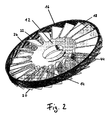
- the Fig. 2 shows a paddle rotor 12 and a blade stator 14 of a turbomolecular pumping stage.
- the blade rotor is surrounded by a wall 16 in the radial direction.
- the blade rotor 12 rotates about a not shown, concentric axis with the direction of rotation 44. From radially inward to radially outward extending rotor blades 18 which are twisted in itself. That is, the angle of attack, which refers to the radially outer ends of the stator blades, is steeper than the angle of origin of the rotor blades.
- the blade rotor is also designed substantially as a disc, ie it extends substantially in the radial direction and has a thickness in the axial direction.
- the Schaufelstator 14 of Fig. 2 is essentially the same as the blade rotor 12, but to a certain extent mirror-inverted.
- the stator blades 20 also spring radially inward on the blade stator 14. However, they can also spring radially outward, for example on the wall 16.
- the wall 16 encloses the blade rotor 12 in the radial direction.
- the recesses 22 are each designed as a groove and extend helically in the axial direction. Between the recesses 22 webs 24 are formed. Between the webs 24 so there is a kind of channel in a pump effective portion.
- the number of depressions 22 and the number of webs 24 are each equal to the number of stator blades 20 and equal to the number of rotor blades 18.
- the depressions 22 are arranged parallel to each other and parallel to the outer ends of the stator blades 20.
- the pumping direction depends on Fig. 2 from top to bottom, ie axially downwards.
- FIG. 3 shows an alternative view of the turbomolecular pumping stage of Fig. 2 , Axially adjacent the vane rotor 12 and the vane stator 14 are arranged.
- the blade rotor is radially enclosed by the wall 16.
- the wall 16 has on its inside the recesses 22 and the webs 24 arranged therebetween.
- the blade rotor 12 rotates with its rotor blades 18 within the wall 16.
- the stator blades 20 of the blade stator 14 are arranged statically.
- the pump-effective partial region that is to say the axial extent of the depressions 22, extends only over the axial width of the rotor blades 18.
- the webs 24 between the depressions 22 extend parallel to the depressions 22. In this case, they are made narrower than the depressions 22.
- the recesses 22 are designed as channel-like, rectangular grooves on the inside of the wall 16. Accordingly, the webs 24 are also formed at right angles.
- the webs 24 and the depressions 22 extend parallel to the radially outer ends of the stator blades 20.
- the webs 24 are each arranged in the circumferential direction at the same location as the stator blades 20.
- the axially lower, ie in the Fig. 3 the rear ends of the recesses 22 are arranged circumferentially between the stator blades 20. A particle flow in a depression 22 can thereby flow unhindered between the stator blades 20.
- the axially lower ends of the recesses 22 face the blade stator.
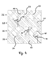
- the Fig. 4 shows a schematic representation of two turbomolecular pumping stages. Axially adjacent, a rotor region 26, a stator region 28, a further rotor region 26 and a further stator region 28 are arranged. In each case a rotor region 26 and an adjacent, axially below arranged stator region 28 form a turbomolecular pumping stage. So it's in Fig. 3 two turbomolecular pumping stages shown.
- turbomolecular pump comprises two rotor and two stator disks, which together can also be referred to as turbomolecular pumping stage.
- the pumping direction runs from top to bottom.
- the rotor blades 18 move from left to right.
- the stator blades 20 are arranged statically.
- depressions 22 are arranged inside on a wall 16, not shown (eg Fig. 2 or 3 ) depressions 22 are arranged. Between the recesses 22 webs 24 are arranged. In this embodiment, the webs 24 are made wider than the depressions 22. The depressions 22 as well as the webs 24 are arranged parallel to the stator blades 20. The angle of attack 46 of the stator blades 20 is therefore equal to the pitch 48 of the depressions 22 at their radially outer ends. The depressions 22 are also located centrally in the circumferential direction between the stator blades 20. The recesses 22 thus extend in the pumping direction from an upper intake side to a lower discharge side continuously over both illustrated turbomolecular pump stages.
- the angle of attack 50 of the rotor blades 18 is 90 ° greater than the angle of attack 46 of the stator blades 20.
- the rotor blades 18 and the stator blades 20 are therefore aligned at their radially outer ends perpendicular to each other.
- the radially outer ends of the rotor blades 18 are therefore also arranged perpendicular to the slope 48 of the recesses 22.
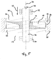
- the Fig. 5 schematically shows some components of a turbomolecular pump according to the invention, in a schematic diagram of a rotor blade designated as a blade rotor 12 with blades 18 which rotatably mounted on a rotor shaft 36 and of which only a rotor disk 12 is shown.
- a blade rotor 12 rotates with the rotor shaft 36 in the rotor rotation direction 44.
- the rotor disk 12 is shown in section.
- the visible rotor blade 18 to the right of the axis of rotation 34 extends axially upward away from the viewer, while the visible rotor blade on the left of the axis of rotation 34 extends axially up to the viewer.
- the rotor shaft 36 and the rotor disk 12 rotate about their axis of rotation 34.
- the rotor shaft 36 is mounted on the discharge side 52 with a rolling bearing 30 radially and preferably also axially.
- the rolling bearing 30 may be embodied for example as a ball bearing or as a cylindrical roller bearing.
- the rotor shaft 36 is mounted with a non-contact and lubrication-free radial bearing 32, preferably with a magnetic bearing.
- the paddle wheel 12 of the Fig. 5 is surrounded by a housing 38.
- the housing 38 has recesses 22 on its inner side facing the blade rotor 12.
- a ring element such as a spacer ring 54 (see. Fig. 1 ) be provided with recesses 22 according to the invention, ie, the component 38 in Fig. 5 then represents such a spacer ring, which cooperates in the manner according to the invention with the rotor disk 12.
- the recesses 22 are arranged helically around the blade rotor 12 in the form of grooves.
- the sense of rotation of the helical depressions 22 corresponds to the rotor rotation direction 44 of the blade rotor 12 Fig. 2 . 3 and 5
- the direction of rotation corresponds to that of a left-handed thread.
- webs 24 are formed between the recesses 22.
- the webs 24 are here designed as wide as the wells 22.
- the pump-active portion of the inner wall of the housing 38 goes into Fig. 5 axially beyond the blade rotor 12 in both directions. In Fig. 5 have the wells 22 a slope which is less than 45 °.
- the depressions 22 are designed as vertically milled grooves.
- a blade stator also referred to as a stator disk
- Axially above and below the blade rotor 12 further turbomolecular pumping stages may be further arranged.
- the structure can therefore, for example, according to the turbomolecular pumping section according to Fig. 1 be elected.
- stator disk 12 adjacent to the rotor disk.
- two or more rotor disks may be arranged axially immediately following one another, before a stator disk follows again, ie at least one pair of immediately successive rotor disks is present, between which no stator disk is arranged in each case.
- stator disks can also be provided exclusively rotor disks, ie on stator discs can be completely dispensed with, at least for a turbomolecular pumping section of the turbomolecular pump.
- a turbomolecular pumping section of a turbomolecular pump for such a structure of one or more turbomolecular pumping sections of a turbomolecular pump and for such a turbomolecular pump as a whole, which otherwise has a typical structure such as in Fig.
- annular or sleeve-shaped elements each having a surrounding the rotor disks wall on at least one pump effective portion of their rotor disks facing side at least one depression is provided, but this is not mandatory.
- a Holweck stator can be arranged around the blade rotor of a turbomolecular pumping stage.
- gas particles that are accelerated outwardly from the rotor against the housing inner wall are deflected by a Holweckstatorgewinde in an axial direction. This in turn becomes the probability of passage increases in the conveying direction and thus improves the power density of a turbomolecular pump.
Landscapes
- Engineering & Computer Science (AREA)
- Mechanical Engineering (AREA)
- General Engineering & Computer Science (AREA)
- Non-Positive Displacement Air Blowers (AREA)
Applications Claiming Priority (1)
| Application Number | Priority Date | Filing Date | Title |
|---|---|---|---|
| DE102014118083.6A DE102014118083A1 (de) | 2014-12-08 | 2014-12-08 | Turbomolekularpumpe |
Publications (3)
| Publication Number | Publication Date |
|---|---|
| EP3032107A2 true EP3032107A2 (fr) | 2016-06-15 |
| EP3032107A3 EP3032107A3 (fr) | 2016-08-31 |
| EP3032107B1 EP3032107B1 (fr) | 2020-04-15 |
Family
ID=53673823
Family Applications (1)
| Application Number | Title | Priority Date | Filing Date |
|---|---|---|---|
| EP15191438.9A Active EP3032107B1 (fr) | 2014-12-08 | 2015-10-26 | Pompe turbomoleculaire |
Country Status (2)
| Country | Link |
|---|---|
| EP (1) | EP3032107B1 (fr) |
| DE (1) | DE102014118083A1 (fr) |
Cited By (2)
| Publication number | Priority date | Publication date | Assignee | Title |
|---|---|---|---|---|
| GB2579028A (en) * | 2018-11-14 | 2020-06-10 | Edwards Ltd | Molecular drag stage |
| CN114352553A (zh) * | 2021-12-31 | 2022-04-15 | 北京中科科仪股份有限公司 | 一种旋涡机构及复合分子泵 |
Families Citing this family (1)
| Publication number | Priority date | Publication date | Assignee | Title |
|---|---|---|---|---|
| JP7555227B2 (ja) * | 2020-10-09 | 2024-09-24 | エドワーズ株式会社 | 真空ポンプとこれを用いた真空排気システム |
Family Cites Families (5)
| Publication number | Priority date | Publication date | Assignee | Title |
|---|---|---|---|---|
| US5358373A (en) * | 1992-04-29 | 1994-10-25 | Varian Associates, Inc. | High performance turbomolecular vacuum pumps |
| DE29717764U1 (de) * | 1997-10-06 | 1997-11-20 | Leybold Vakuum GmbH, 50968 Köln | Stator für eine Turbomolekularvakuumpumpe |
| DE10010371A1 (de) * | 2000-03-02 | 2001-09-06 | Pfeiffer Vacuum Gmbh | Turbomolekularpumpe |
| DE10111546A1 (de) * | 2000-05-15 | 2002-01-03 | Pfeiffer Vacuum Gmbh | Gasreibungspumpe |
| DE102013213815A1 (de) * | 2013-07-15 | 2015-01-15 | Pfeiffer Vacuum Gmbh | Vakuumpumpe |
-
2014
- 2014-12-08 DE DE102014118083.6A patent/DE102014118083A1/de not_active Withdrawn
-
2015
- 2015-10-26 EP EP15191438.9A patent/EP3032107B1/fr active Active
Non-Patent Citations (1)
| Title |
|---|
| None |
Cited By (3)
| Publication number | Priority date | Publication date | Assignee | Title |
|---|---|---|---|---|
| GB2579028A (en) * | 2018-11-14 | 2020-06-10 | Edwards Ltd | Molecular drag stage |
| CN114352553A (zh) * | 2021-12-31 | 2022-04-15 | 北京中科科仪股份有限公司 | 一种旋涡机构及复合分子泵 |
| CN114352553B (zh) * | 2021-12-31 | 2024-01-09 | 北京中科科仪股份有限公司 | 一种旋涡机构及复合分子泵 |
Also Published As
| Publication number | Publication date |
|---|---|
| EP3032107B1 (fr) | 2020-04-15 |
| DE102014118083A1 (de) | 2016-06-09 |
| EP3032107A3 (fr) | 2016-08-31 |
Similar Documents
| Publication | Publication Date | Title |
|---|---|---|
| EP2025945B1 (fr) | Machine de traitement des écoulements dotée d'un creux de paroi de canal de ceinture | |
| DE69114647T2 (de) | Axialströmungsgebläse. | |
| EP2933497B1 (fr) | Pompe à vide | |
| DE1817430A1 (de) | Regenerativkompressor | |
| CH674552A5 (fr) | ||
| EP2295812B1 (fr) | Récipient repliable | |
| DE2331614A1 (de) | Seitenkanal-geblaese | |
| EP3032107B1 (fr) | Pompe turbomoleculaire | |
| WO2016110373A1 (fr) | Soufflante à canal latéral pour un moteur à combustion interne | |
| EP2994614A1 (fr) | Rotor pour turbomachine thermique | |
| EP3088743B1 (fr) | Étage de pompe a vide à canal latéral avec un barrage de canal qui présente une rampe du côté de l'aspiration | |
| EP2994615A1 (fr) | Rotor pour turbomachine thermique | |
| EP2863063B1 (fr) | Pompe à vide | |
| DE10210404A1 (de) | Verfahren zur Herstellung des Rotors einer Reibungsvakuumpumpe sowie nach diesem Verfahren hergestellter Rotor | |
| DE102015003224A1 (de) | Selbstansaugende Pumpe | |
| EP4194700B1 (fr) | Pompe à vide avec étage de pompe de holweck à géométrie de holweck variable | |
| EP2886870B1 (fr) | Pompe à vide avec géométrie d'admission perfectionnée | |
| DE202011002809U1 (de) | Statorelement sowie Hochvakuumpumpe | |
| EP3133290B1 (fr) | Pompe à vide | |
| WO2003031823A1 (fr) | Pompe a vide rotative a refoulement axial | |
| EP3877653B1 (fr) | Machine hydraulique à plusieurs étages | |
| EP3032106B1 (fr) | Pompe à vide | |
| DE102014100207B4 (de) | Statorscheibe | |
| EP1573208A1 (fr) | Conduite d'aspiration | |
| EP2937525A1 (fr) | Moteur d'aéronef |
Legal Events
| Date | Code | Title | Description |
|---|---|---|---|
| PUAI | Public reference made under article 153(3) epc to a published international application that has entered the european phase |
Free format text: ORIGINAL CODE: 0009012 |
|
| AK | Designated contracting states |
Kind code of ref document: A2 Designated state(s): AL AT BE BG CH CY CZ DE DK EE ES FI FR GB GR HR HU IE IS IT LI LT LU LV MC MK MT NL NO PL PT RO RS SE SI SK SM TR |
|
| AX | Request for extension of the european patent |
Extension state: BA ME |
|
| PUAL | Search report despatched |
Free format text: ORIGINAL CODE: 0009013 |
|
| AK | Designated contracting states |
Kind code of ref document: A3 Designated state(s): AL AT BE BG CH CY CZ DE DK EE ES FI FR GB GR HR HU IE IS IT LI LT LU LV MC MK MT NL NO PL PT RO RS SE SI SK SM TR |
|
| AX | Request for extension of the european patent |
Extension state: BA ME |
|
| RIC1 | Information provided on ipc code assigned before grant |
Ipc: F04D 29/54 20060101ALI20160728BHEP Ipc: F04D 29/32 20060101ALI20160728BHEP Ipc: F04D 29/64 20060101ALI20160728BHEP Ipc: F04D 19/04 20060101AFI20160728BHEP |
|
| STAA | Information on the status of an ep patent application or granted ep patent |
Free format text: STATUS: REQUEST FOR EXAMINATION WAS MADE |
|
| 17P | Request for examination filed |
Effective date: 20170130 |
|
| RBV | Designated contracting states (corrected) |
Designated state(s): AL AT BE BG CH CY CZ DE DK EE ES FI FR GB GR HR HU IE IS IT LI LT LU LV MC MK MT NL NO PL PT RO RS SE SI SK SM TR |
|
| RIC1 | Information provided on ipc code assigned before grant |
Ipc: F04D 29/68 20060101ALI20190924BHEP Ipc: F04D 29/52 20060101ALI20190924BHEP Ipc: F04D 19/04 20060101AFI20190924BHEP |
|
| GRAP | Despatch of communication of intention to grant a patent |
Free format text: ORIGINAL CODE: EPIDOSNIGR1 |
|
| STAA | Information on the status of an ep patent application or granted ep patent |
Free format text: STATUS: GRANT OF PATENT IS INTENDED |
|
| INTG | Intention to grant announced |
Effective date: 20191105 |
|
| GRAS | Grant fee paid |
Free format text: ORIGINAL CODE: EPIDOSNIGR3 |
|
| GRAA | (expected) grant |
Free format text: ORIGINAL CODE: 0009210 |
|
| STAA | Information on the status of an ep patent application or granted ep patent |
Free format text: STATUS: THE PATENT HAS BEEN GRANTED |
|
| AK | Designated contracting states |
Kind code of ref document: B1 Designated state(s): AL AT BE BG CH CY CZ DE DK EE ES FI FR GB GR HR HU IE IS IT LI LT LU LV MC MK MT NL NO PL PT RO RS SE SI SK SM TR |
|
| REG | Reference to a national code |
Ref country code: CH Ref legal event code: EP |
|
| REG | Reference to a national code |
Ref country code: DE Ref legal event code: R096 Ref document number: 502015012269 Country of ref document: DE |
|
| REG | Reference to a national code |
Ref country code: IE Ref legal event code: FG4D Free format text: LANGUAGE OF EP DOCUMENT: GERMAN |
|
| REG | Reference to a national code |
Ref country code: AT Ref legal event code: REF Ref document number: 1257626 Country of ref document: AT Kind code of ref document: T Effective date: 20200515 |
|
| REG | Reference to a national code |
Ref country code: NL Ref legal event code: MP Effective date: 20200415 |
|
| REG | Reference to a national code |
Ref country code: LT Ref legal event code: MG4D |
|
| PG25 | Lapsed in a contracting state [announced via postgrant information from national office to epo] |
Ref country code: NL Free format text: LAPSE BECAUSE OF FAILURE TO SUBMIT A TRANSLATION OF THE DESCRIPTION OR TO PAY THE FEE WITHIN THE PRESCRIBED TIME-LIMIT Effective date: 20200415 Ref country code: SE Free format text: LAPSE BECAUSE OF FAILURE TO SUBMIT A TRANSLATION OF THE DESCRIPTION OR TO PAY THE FEE WITHIN THE PRESCRIBED TIME-LIMIT Effective date: 20200415 Ref country code: GR Free format text: LAPSE BECAUSE OF FAILURE TO SUBMIT A TRANSLATION OF THE DESCRIPTION OR TO PAY THE FEE WITHIN THE PRESCRIBED TIME-LIMIT Effective date: 20200716 Ref country code: FI Free format text: LAPSE BECAUSE OF FAILURE TO SUBMIT A TRANSLATION OF THE DESCRIPTION OR TO PAY THE FEE WITHIN THE PRESCRIBED TIME-LIMIT Effective date: 20200415 Ref country code: IS Free format text: LAPSE BECAUSE OF FAILURE TO SUBMIT A TRANSLATION OF THE DESCRIPTION OR TO PAY THE FEE WITHIN THE PRESCRIBED TIME-LIMIT Effective date: 20200815 Ref country code: PT Free format text: LAPSE BECAUSE OF FAILURE TO SUBMIT A TRANSLATION OF THE DESCRIPTION OR TO PAY THE FEE WITHIN THE PRESCRIBED TIME-LIMIT Effective date: 20200817 Ref country code: NO Free format text: LAPSE BECAUSE OF FAILURE TO SUBMIT A TRANSLATION OF THE DESCRIPTION OR TO PAY THE FEE WITHIN THE PRESCRIBED TIME-LIMIT Effective date: 20200715 Ref country code: LT Free format text: LAPSE BECAUSE OF FAILURE TO SUBMIT A TRANSLATION OF THE DESCRIPTION OR TO PAY THE FEE WITHIN THE PRESCRIBED TIME-LIMIT Effective date: 20200415 |
|
| PG25 | Lapsed in a contracting state [announced via postgrant information from national office to epo] |
Ref country code: LV Free format text: LAPSE BECAUSE OF FAILURE TO SUBMIT A TRANSLATION OF THE DESCRIPTION OR TO PAY THE FEE WITHIN THE PRESCRIBED TIME-LIMIT Effective date: 20200415 Ref country code: RS Free format text: LAPSE BECAUSE OF FAILURE TO SUBMIT A TRANSLATION OF THE DESCRIPTION OR TO PAY THE FEE WITHIN THE PRESCRIBED TIME-LIMIT Effective date: 20200415 Ref country code: BG Free format text: LAPSE BECAUSE OF FAILURE TO SUBMIT A TRANSLATION OF THE DESCRIPTION OR TO PAY THE FEE WITHIN THE PRESCRIBED TIME-LIMIT Effective date: 20200715 Ref country code: HR Free format text: LAPSE BECAUSE OF FAILURE TO SUBMIT A TRANSLATION OF THE DESCRIPTION OR TO PAY THE FEE WITHIN THE PRESCRIBED TIME-LIMIT Effective date: 20200415 |
|
| PG25 | Lapsed in a contracting state [announced via postgrant information from national office to epo] |
Ref country code: AL Free format text: LAPSE BECAUSE OF FAILURE TO SUBMIT A TRANSLATION OF THE DESCRIPTION OR TO PAY THE FEE WITHIN THE PRESCRIBED TIME-LIMIT Effective date: 20200415 |
|
| REG | Reference to a national code |
Ref country code: DE Ref legal event code: R097 Ref document number: 502015012269 Country of ref document: DE |
|
| PG25 | Lapsed in a contracting state [announced via postgrant information from national office to epo] |
Ref country code: RO Free format text: LAPSE BECAUSE OF FAILURE TO SUBMIT A TRANSLATION OF THE DESCRIPTION OR TO PAY THE FEE WITHIN THE PRESCRIBED TIME-LIMIT Effective date: 20200415 Ref country code: EE Free format text: LAPSE BECAUSE OF FAILURE TO SUBMIT A TRANSLATION OF THE DESCRIPTION OR TO PAY THE FEE WITHIN THE PRESCRIBED TIME-LIMIT Effective date: 20200415 Ref country code: DK Free format text: LAPSE BECAUSE OF FAILURE TO SUBMIT A TRANSLATION OF THE DESCRIPTION OR TO PAY THE FEE WITHIN THE PRESCRIBED TIME-LIMIT Effective date: 20200415 Ref country code: SM Free format text: LAPSE BECAUSE OF FAILURE TO SUBMIT A TRANSLATION OF THE DESCRIPTION OR TO PAY THE FEE WITHIN THE PRESCRIBED TIME-LIMIT Effective date: 20200415 Ref country code: ES Free format text: LAPSE BECAUSE OF FAILURE TO SUBMIT A TRANSLATION OF THE DESCRIPTION OR TO PAY THE FEE WITHIN THE PRESCRIBED TIME-LIMIT Effective date: 20200415 |
|
| PLBE | No opposition filed within time limit |
Free format text: ORIGINAL CODE: 0009261 |
|
| STAA | Information on the status of an ep patent application or granted ep patent |
Free format text: STATUS: NO OPPOSITION FILED WITHIN TIME LIMIT |
|
| PG25 | Lapsed in a contracting state [announced via postgrant information from national office to epo] |
Ref country code: PL Free format text: LAPSE BECAUSE OF FAILURE TO SUBMIT A TRANSLATION OF THE DESCRIPTION OR TO PAY THE FEE WITHIN THE PRESCRIBED TIME-LIMIT Effective date: 20200415 Ref country code: SK Free format text: LAPSE BECAUSE OF FAILURE TO SUBMIT A TRANSLATION OF THE DESCRIPTION OR TO PAY THE FEE WITHIN THE PRESCRIBED TIME-LIMIT Effective date: 20200415 |
|
| 26N | No opposition filed |
Effective date: 20210118 |
|
| PG25 | Lapsed in a contracting state [announced via postgrant information from national office to epo] |
Ref country code: SI Free format text: LAPSE BECAUSE OF FAILURE TO SUBMIT A TRANSLATION OF THE DESCRIPTION OR TO PAY THE FEE WITHIN THE PRESCRIBED TIME-LIMIT Effective date: 20200415 |
|
| REG | Reference to a national code |
Ref country code: CH Ref legal event code: PL |
|
| PG25 | Lapsed in a contracting state [announced via postgrant information from national office to epo] |
Ref country code: MC Free format text: LAPSE BECAUSE OF FAILURE TO SUBMIT A TRANSLATION OF THE DESCRIPTION OR TO PAY THE FEE WITHIN THE PRESCRIBED TIME-LIMIT Effective date: 20200415 Ref country code: LU Free format text: LAPSE BECAUSE OF NON-PAYMENT OF DUE FEES Effective date: 20201026 |
|
| REG | Reference to a national code |
Ref country code: BE Ref legal event code: MM Effective date: 20201031 |
|
| PG25 | Lapsed in a contracting state [announced via postgrant information from national office to epo] |
Ref country code: FR Free format text: LAPSE BECAUSE OF NON-PAYMENT OF DUE FEES Effective date: 20201031 |
|
| PG25 | Lapsed in a contracting state [announced via postgrant information from national office to epo] |
Ref country code: LI Free format text: LAPSE BECAUSE OF NON-PAYMENT OF DUE FEES Effective date: 20201031 Ref country code: CH Free format text: LAPSE BECAUSE OF NON-PAYMENT OF DUE FEES Effective date: 20201031 Ref country code: BE Free format text: LAPSE BECAUSE OF NON-PAYMENT OF DUE FEES Effective date: 20201031 |
|
| PG25 | Lapsed in a contracting state [announced via postgrant information from national office to epo] |
Ref country code: IE Free format text: LAPSE BECAUSE OF NON-PAYMENT OF DUE FEES Effective date: 20201026 |
|
| REG | Reference to a national code |
Ref country code: AT Ref legal event code: MM01 Ref document number: 1257626 Country of ref document: AT Kind code of ref document: T Effective date: 20201026 |
|
| PG25 | Lapsed in a contracting state [announced via postgrant information from national office to epo] |
Ref country code: AT Free format text: LAPSE BECAUSE OF NON-PAYMENT OF DUE FEES Effective date: 20201026 |
|
| PG25 | Lapsed in a contracting state [announced via postgrant information from national office to epo] |
Ref country code: TR Free format text: LAPSE BECAUSE OF FAILURE TO SUBMIT A TRANSLATION OF THE DESCRIPTION OR TO PAY THE FEE WITHIN THE PRESCRIBED TIME-LIMIT Effective date: 20200415 Ref country code: MT Free format text: LAPSE BECAUSE OF FAILURE TO SUBMIT A TRANSLATION OF THE DESCRIPTION OR TO PAY THE FEE WITHIN THE PRESCRIBED TIME-LIMIT Effective date: 20200415 Ref country code: CY Free format text: LAPSE BECAUSE OF FAILURE TO SUBMIT A TRANSLATION OF THE DESCRIPTION OR TO PAY THE FEE WITHIN THE PRESCRIBED TIME-LIMIT Effective date: 20200415 |
|
| PG25 | Lapsed in a contracting state [announced via postgrant information from national office to epo] |
Ref country code: MK Free format text: LAPSE BECAUSE OF FAILURE TO SUBMIT A TRANSLATION OF THE DESCRIPTION OR TO PAY THE FEE WITHIN THE PRESCRIBED TIME-LIMIT Effective date: 20200415 |
|
| PGFP | Annual fee paid to national office [announced via postgrant information from national office to epo] |
Ref country code: GB Payment date: 20251022 Year of fee payment: 11 |
|
| PGFP | Annual fee paid to national office [announced via postgrant information from national office to epo] |
Ref country code: IT Payment date: 20251024 Year of fee payment: 11 |
|
| PGFP | Annual fee paid to national office [announced via postgrant information from national office to epo] |
Ref country code: CZ Payment date: 20251020 Year of fee payment: 11 |
|
| PGFP | Annual fee paid to national office [announced via postgrant information from national office to epo] |
Ref country code: DE Payment date: 20251229 Year of fee payment: 11 |