EP3032125A1 - Frein à disque et ses composants - Google Patents
Frein à disque et ses composants Download PDFInfo
- Publication number
- EP3032125A1 EP3032125A1 EP14196853.7A EP14196853A EP3032125A1 EP 3032125 A1 EP3032125 A1 EP 3032125A1 EP 14196853 A EP14196853 A EP 14196853A EP 3032125 A1 EP3032125 A1 EP 3032125A1
- Authority
- EP
- European Patent Office
- Prior art keywords
- caliper
- wheel axle
- connecting element
- carrier
- mounting
- Prior art date
- Legal status (The legal status is an assumption and is not a legal conclusion. Google has not performed a legal analysis and makes no representation as to the accuracy of the status listed.)
- Granted
Links
Images


Classifications
-
- F—MECHANICAL ENGINEERING; LIGHTING; HEATING; WEAPONS; BLASTING
- F16—ENGINEERING ELEMENTS AND UNITS; GENERAL MEASURES FOR PRODUCING AND MAINTAINING EFFECTIVE FUNCTIONING OF MACHINES OR INSTALLATIONS; THERMAL INSULATION IN GENERAL
- F16D—COUPLINGS FOR TRANSMITTING ROTATION; CLUTCHES; BRAKES
- F16D55/00—Brakes with substantially-radial braking surfaces pressed together in axial direction, e.g. disc brakes
- F16D55/02—Brakes with substantially-radial braking surfaces pressed together in axial direction, e.g. disc brakes with axially-movable discs or pads pressed against axially-located rotating members
- F16D55/22—Brakes with substantially-radial braking surfaces pressed together in axial direction, e.g. disc brakes with axially-movable discs or pads pressed against axially-located rotating members by clamping an axially-located rotating disc between movable braking members, e.g. movable brake discs or brake pads
-
- F—MECHANICAL ENGINEERING; LIGHTING; HEATING; WEAPONS; BLASTING
- F16—ENGINEERING ELEMENTS AND UNITS; GENERAL MEASURES FOR PRODUCING AND MAINTAINING EFFECTIVE FUNCTIONING OF MACHINES OR INSTALLATIONS; THERMAL INSULATION IN GENERAL
- F16D—COUPLINGS FOR TRANSMITTING ROTATION; CLUTCHES; BRAKES
- F16D55/00—Brakes with substantially-radial braking surfaces pressed together in axial direction, e.g. disc brakes
- F16D2055/0004—Parts or details of disc brakes
- F16D2055/0008—Brake supports
-
- F—MECHANICAL ENGINEERING; LIGHTING; HEATING; WEAPONS; BLASTING
- F16—ENGINEERING ELEMENTS AND UNITS; GENERAL MEASURES FOR PRODUCING AND MAINTAINING EFFECTIVE FUNCTIONING OF MACHINES OR INSTALLATIONS; THERMAL INSULATION IN GENERAL
- F16D—COUPLINGS FOR TRANSMITTING ROTATION; CLUTCHES; BRAKES
- F16D55/00—Brakes with substantially-radial braking surfaces pressed together in axial direction, e.g. disc brakes
- F16D2055/0004—Parts or details of disc brakes
- F16D2055/0016—Brake calipers
- F16D2055/002—Brake calipers assembled from a plurality of parts
Definitions
- the present invention refers to a disc brake, preferably for utility vehicles, to a caliper for such a disc brake and to a carrier for such a caliper, and in particular to the way how a caliper or a carrier is fixed to a connecting element, which is arranged on a wheel axle.
- a connecting element also called torque plate
- the caliper or carrier supporting such caliper of a disc brake can be mounted to the connecting element by means of mounting bolts, which are arranged to both sides of the wheel axle.
- mounting bolts which are arranged to both sides of the wheel axle.
- the mounting bolts between the connecting element and the caliper or carrier in a direction in parallel to the brake disc axis and lateral thereto.
- the mounting bolts can be mounted radially so as to extend perpendicularly to the wheel axle.
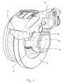
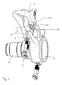
- Such typical radial-mount type of disc brake according to the prior art is exemplarily shown in the perspective view of Fig. 1 and in the explosive view of Fig. 2 .
- the disc brake according to the prior art comprises a caliper 1 for receiving an actuation mechanism (not shown) and overlapping a brake disc 2.
- the caliper 1 is slideably supported on a carrier 3, which is bolted to a connecting element or torque plate 4.
- the connecting element 4 is fixed to a wheel axle 5, so that the entire disc brake can be mounted on the wheel axle 5.
- connection between the connecting element 4 of the wheel axle 5 and the carrier 3 is realized by several mounting bolts 6, two of which are arranged to both sides of the wheel axle 5 and which each traverse through holes 7 in laterally arranged sections 8 of the connecting element 4, so as to become received by threaded openings 9 being arranged in corresponding lateral mounting sections 10 of the carrier 3, respectively.
- flat abutment surfaces 11 of the carrier 3 do attach to flat abutment surfaces 12 of the connecting element 4, which abutment surfaces 11 and 12 are arranged parallel to a plane extending in and being parallel to the longitudinal direction of the wheel axle 5 or the axis of the brake disc 2.
- radial-mount type disc brakes are, e.g., known from EP 0 971 144 B1 and DE 100 63 787 A1 .
- the mounting bolts have to be dimensioned large enough to take up such forces entirely.
- the lateral sections comprising the through holes for the mounting bolts at the torque plate on the one hand and the lateral mounting sections comprising the threaded openings for the mounting bolts at the caliper or carrier on the other have to be substantially dimensioned as well, which leads to larger carrier or caliper designs in this respect.
- Such object is solved by a disc brake according to claim 1 and claim 2, respectively, and furthermore by a corresponding caliper for a disc brake according to claim 7, by a carrier for a caliper of a disc brake according to claim 9 and by a connecting element for a wheel axle according to claim 11.
- the caliper or the carrier comprises at least one abutment surface, which does attach to at least one abutment surface of the connecting element, when the caliper or the carrier are fixed to the connecting element by means of several mounting bolts.
- at least one abutment surface of said connecting element and at least one abutment surface of said caliper or said carrier, which abutment surfaces are in attachment which each other, are inclined in relation to a plane extending in parallel to the longitudinal axis of the wheel axle.
- the angle of inclination could be selected deliberately depending on constructional and manufacturing needs. According to the invention the angle of inclination with respect to the plane being defined in parallel to the longitudinal direction or axis of the wheel axle could be in a range of 20 to 40 degrees, preferably in a range of 25 to 35 degrees and most preferably 30 degrees.
- the connecting element or the torque plate comprises support sections at both sides of the wheel axle, which support sections both comprise inclined abutment surfaces.
- the mounting bolts do traverse the support sections and will be received in threaded openings, which are arranged in mounting sections of the caliper or the carrier, correspondingly, which mounting sections comprise abutment surfaces being congruently shaped and inclined in accordance with the inclined surfaces of the connecting element.
- only one support section on one side of the wheel axle comprises an inclined abutment surface.
- the opposite mounting section of the caliper or the carrier comprises such inclined abutment surface.
- one accurate bolt comprises a preferably radial guiding surface to cooperate with a corresponding guiding surface in the mounting section of the caliper or carrier, so that the position of the torque plate or connecting element can be controlled in lateral direction.
- the support sections could comprise said inclined abutment surfaces to both sides of the mounting bolts, when seen in the direction of the longitudinal axis of the wheel axle, which abutment surfaces are inclined in opposite directions with respect to each other.
- the mounting sections of the caliper or carrier comprise correspondingly shaped and inclined surfaces which do come into abutment with the inclined surfaces of the support sections, respectively.
- the support section on one side of the wheel axle could comprise a different height than the support section on the opposite side of the wheel axle.
- At least one support section comprises a geometrically shaped element which corresponds with a correspondingly shaped element of the related mounting section of the caliper or carrier.
- Such geometrically shaped elements do form some kind of engagement mechanism between the connecting element and the carrier or the caliper, but having a large enough play so as to not hinder the assembly process, and could include different shapes, configurations and dimensions, e.g. such as steps, recesses, indents or similar. For example, steps could be arranged about halfway between the two mounting bolts of one support section.
- the provision of such elements on both the support section of the torque plate and the corresponding mounting section of the carrier or caliper ensures that no incorrectly shaped caliper or carrier will be installed on the torque plate, which increases the safety during assembly.
- Fig. 3 shows a first embodiment of the invention in an explosive view.
- a carrier 13 is to be mounted on a connecting element or torque plate 14 via four mounting bolts 15.
- the connecting element 14 is fixedly connected to a wheel axle 16.
- the connecting element 14 comprises to both sides of the wheel axle 16 one support section 17, respectively. Accordingly, the carrier 13 comprises mounting sections 18 being arranged at corresponding lateral locations.
- the support sections 17 comprise through holes 19 which receive the mounting bolts 15, whereas the mounting sections 18 of the carrier 13 comprise threaded openings 20, into which the mounting bolts 15 will be fixedly inserted.
- the support sections 17 comprise inclined abutments surfaces 21, the inclination of which is directed towards a plane being defined in parallel to the longitudinal direction or axis of the wheel axle 16.
- the mounting sections 18 of the carrier 13 comprise inclined abutment surfaces 22, which are congruently inclined with respect to the inclination of the abutment surfaces 21 of the torque plate 14.
- the inclined surfaces 21 and 22 of both the support section 17 and of the mounting section 18 are provided at both sides of a symmetry line being defined by the mounting bolts 15, in which the inclination of the abutment surfaces 21 and 22 is directed towards each other so as to form some kind of wedge-like connection between the carrier 13 and the connecting element 14.
- FIG. 4 A further embodiment is shown in Fig. 4 .
- only one support section 17 on one side of the wheel axle 16 comprises an inclined abutment surface 21, whereas the other support section 17 opposite of the wheel axle 16 comprises a flat abutment surface 23, which cooperates with a flat abutment surface 24 of the carrier 13.
- the outer mounting bolt 15 in the support section 17 comprising the flat surfaces 23 comprises a radial guiding surface 25, which cooperates with a corresponding radial ring (not shown) in an opening of the corresponding mounting section 18 of the carrier 13.
- the guiding ring 25 serves to accurately guide the carrier 13 on the torque plate 14 laterally.
- Fig. 6 schematically shows a sectional view of one side of the connecting element 14.
- the support section 17 comprises a step 26 which is arranged halfway between the two bolts (indicated by the dotted lines of the through holes), which step 26 will match with a correspondingly shaped step (not shown) of the related mounting section 18 of the carrier 13, so that the correct carrier 13 fits to the correct connecting element 14 in an accurate way.
- the abutment surface 27 relating to the inner mounting bolt 15 is thus flat. Mistakes during assembly can be avoided thereby.
- all kind of geometrically shaped elements, which allow matching between two components could be used for that purpose.
Landscapes
- Engineering & Computer Science (AREA)
- General Engineering & Computer Science (AREA)
- Mechanical Engineering (AREA)
- Braking Arrangements (AREA)
Priority Applications (3)
| Application Number | Priority Date | Filing Date | Title |
|---|---|---|---|
| EP14196853.7A EP3032125B2 (fr) | 2014-12-08 | 2014-12-08 | Frein à disque et ses composants |
| PCT/EP2015/079032 WO2016091909A1 (fr) | 2014-12-08 | 2015-12-08 | Frein à disque et ses éléments |
| US15/534,336 US20170343066A1 (en) | 2014-12-08 | 2015-12-08 | Disc Brake And Components Thereof |
Applications Claiming Priority (1)
| Application Number | Priority Date | Filing Date | Title |
|---|---|---|---|
| EP14196853.7A EP3032125B2 (fr) | 2014-12-08 | 2014-12-08 | Frein à disque et ses composants |
Publications (3)
| Publication Number | Publication Date |
|---|---|
| EP3032125A1 true EP3032125A1 (fr) | 2016-06-15 |
| EP3032125B1 EP3032125B1 (fr) | 2018-11-14 |
| EP3032125B2 EP3032125B2 (fr) | 2022-02-23 |
Family
ID=52013937
Family Applications (1)
| Application Number | Title | Priority Date | Filing Date |
|---|---|---|---|
| EP14196853.7A Active EP3032125B2 (fr) | 2014-12-08 | 2014-12-08 | Frein à disque et ses composants |
Country Status (3)
| Country | Link |
|---|---|
| US (1) | US20170343066A1 (fr) |
| EP (1) | EP3032125B2 (fr) |
| WO (1) | WO2016091909A1 (fr) |
Cited By (2)
| Publication number | Priority date | Publication date | Assignee | Title |
|---|---|---|---|---|
| EP3101302A3 (fr) * | 2015-06-02 | 2016-12-21 | KNORR-BREMSE Systeme für Nutzfahrzeuge GmbH | Support de frein pour un frein à disque |
| WO2019096351A1 (fr) * | 2017-11-17 | 2019-05-23 | Bpw Bergische Achsen Kg | Ensemble de freinage pour véhicule commercial |
Families Citing this family (2)
| Publication number | Priority date | Publication date | Assignee | Title |
|---|---|---|---|---|
| USD843901S1 (en) * | 2017-04-21 | 2019-03-26 | Hasport Performance, Inc. | Caliper bracket |
| JP2023089312A (ja) * | 2020-04-24 | 2023-06-28 | 日立Astemo株式会社 | ディスクブレーキ |
Citations (7)
| Publication number | Priority date | Publication date | Assignee | Title |
|---|---|---|---|---|
| DE10063787A1 (de) | 2000-12-21 | 2002-06-27 | Porsche Ag | Bremseinrichtung |
| EP1482198A2 (fr) * | 2003-05-28 | 2004-12-01 | Nissin Kogyo Co., Ltd. | Structure de fixation d'un étrier de frein à disque pour véhicules |
| EP0971144B1 (fr) | 1998-07-06 | 2005-11-30 | Sumitomo Electric Industries, Ltd. | Disque de frein à montage radial |
| EP1715211A1 (fr) * | 2005-04-21 | 2006-10-25 | Bendix Commercial Vehicle Systems, LLC | Etrier de frein monté radialement |
| DE102005026720A1 (de) * | 2005-06-09 | 2006-12-21 | Wabco Radbremsen Gmbh | Scheibenbremse für ein Landfahrzeug |
| EP1801447A2 (fr) * | 2005-12-21 | 2007-06-27 | Performance Friction Corporation | Ensemble d'étrier de frein |
| JP2011094767A (ja) * | 2009-11-02 | 2011-05-12 | Nissin Kogyo Co Ltd | 車両用ディスクブレーキのキャリパボディ |
Family Cites Families (11)
| Publication number | Priority date | Publication date | Assignee | Title |
|---|---|---|---|---|
| DE1801447U (de) | 1959-10-10 | 1959-12-03 | Guenter Kuehn | Geraet zum loeschen der glut von zigaretten u. dgl. |
| US3999635A (en) * | 1975-10-06 | 1976-12-28 | The B. F. Goodrich Company | Disc brake caliper and lining carrier supporting means |
| US5884980A (en) * | 1996-10-31 | 1999-03-23 | Robert Bosch Technologies Corporation | Vehicle brake and hub attachment system and method |
| BR0306800A (pt) * | 2002-02-08 | 2004-12-07 | Knorr Bremse Systeme | Freio a disco com dispositivo de reajuste acionado eletricamente |
| US7873724B2 (en) * | 2003-12-05 | 2011-01-18 | Microsoft Corporation | Systems and methods for guiding allocation of computational resources in automated perceptual systems |
| JP2006064026A (ja) | 2004-08-25 | 2006-03-09 | Toyota Motor Corp | ピンスライド型ディスクブレーキ装置 |
| US20070125606A1 (en) * | 2005-12-07 | 2007-06-07 | Jui-Pin Chen | Adjusting device for positioning brake lining relative to a brake disk of a bicycle |
| US20080135352A1 (en) | 2006-12-12 | 2008-06-12 | Bendix Spicer Foundation Brake Llc | Brake caliper vertical mounting assembly joint arrangement |
| US9353810B2 (en) * | 2013-02-21 | 2016-05-31 | Kelsey-Hayes Company | Disc brake assembly with non-rotatable vehicle component and method for producing same |
| US9506512B2 (en) * | 2013-10-03 | 2016-11-29 | Bendix Spicer Foundation Brake Llc | Brake carrier mounting arrangement |
| US20150377310A1 (en) * | 2014-06-30 | 2015-12-31 | Arvinmeritor Technology, Llc | Brake Assembly Bonded with an Adhesive |
-
2014
- 2014-12-08 EP EP14196853.7A patent/EP3032125B2/fr active Active
-
2015
- 2015-12-08 US US15/534,336 patent/US20170343066A1/en not_active Abandoned
- 2015-12-08 WO PCT/EP2015/079032 patent/WO2016091909A1/fr not_active Ceased
Patent Citations (7)
| Publication number | Priority date | Publication date | Assignee | Title |
|---|---|---|---|---|
| EP0971144B1 (fr) | 1998-07-06 | 2005-11-30 | Sumitomo Electric Industries, Ltd. | Disque de frein à montage radial |
| DE10063787A1 (de) | 2000-12-21 | 2002-06-27 | Porsche Ag | Bremseinrichtung |
| EP1482198A2 (fr) * | 2003-05-28 | 2004-12-01 | Nissin Kogyo Co., Ltd. | Structure de fixation d'un étrier de frein à disque pour véhicules |
| EP1715211A1 (fr) * | 2005-04-21 | 2006-10-25 | Bendix Commercial Vehicle Systems, LLC | Etrier de frein monté radialement |
| DE102005026720A1 (de) * | 2005-06-09 | 2006-12-21 | Wabco Radbremsen Gmbh | Scheibenbremse für ein Landfahrzeug |
| EP1801447A2 (fr) * | 2005-12-21 | 2007-06-27 | Performance Friction Corporation | Ensemble d'étrier de frein |
| JP2011094767A (ja) * | 2009-11-02 | 2011-05-12 | Nissin Kogyo Co Ltd | 車両用ディスクブレーキのキャリパボディ |
Cited By (3)
| Publication number | Priority date | Publication date | Assignee | Title |
|---|---|---|---|---|
| EP3101302A3 (fr) * | 2015-06-02 | 2016-12-21 | KNORR-BREMSE Systeme für Nutzfahrzeuge GmbH | Support de frein pour un frein à disque |
| WO2019096351A1 (fr) * | 2017-11-17 | 2019-05-23 | Bpw Bergische Achsen Kg | Ensemble de freinage pour véhicule commercial |
| CN111480018A (zh) * | 2017-11-17 | 2020-07-31 | Bpw矿用轴公司 | 用于商用车的制动组件 |
Also Published As
| Publication number | Publication date |
|---|---|
| WO2016091909A1 (fr) | 2016-06-16 |
| EP3032125B2 (fr) | 2022-02-23 |
| US20170343066A1 (en) | 2017-11-30 |
| EP3032125B1 (fr) | 2018-11-14 |
Similar Documents
| Publication | Publication Date | Title |
|---|---|---|
| JP5566916B2 (ja) | 機外側ハブバレル取付けロータ | |
| EP3032125B1 (fr) | Frein à disque et ses composants | |
| EP2543905B1 (fr) | Ensemble de frein doté d'une pince de montage | |
| EP2743533A2 (fr) | Ensemble d'étrier de frein comportant une protection de coussin | |
| US8613347B2 (en) | Arrangement of a brake disc on a wheel hub | |
| EP3287659B2 (fr) | Dispositif de frein à disque pour un véhicule | |
| DE102011122984B3 (de) | Bremsrotoranordnung | |
| US9422992B2 (en) | Disc brake with a spring attachment | |
| EP2959178B1 (fr) | Ensemble frein à disque ayant un composant de véhicule qui ne peut pas tourner et procédé permettant de produire cet ensemble frein à disque | |
| US20100282551A1 (en) | Brake disk | |
| US8056684B2 (en) | Vehicle drum-in-hat disc brake assembly and method for producing same | |
| EP3682133B1 (fr) | Ensemble rotor de frein à disque | |
| US20110042172A1 (en) | Braking Device With A Brake Caliper Attachment | |
| EP3184841B1 (fr) | Frein a disque | |
| EP3150878B1 (fr) | Ensemble de frein comportant un pont | |
| EP2971839B1 (fr) | Plaquette de frein sous tension | |
| US9994205B2 (en) | Axis of a land vehicle, land vehicle with such a suspension and disk brake and brake support of such land vehicle | |
| DE102004017383A1 (de) | Elektromechanische Scheibenbremse | |
| DE102014207369A1 (de) | Scheibenrad | |
| EP3779226B2 (fr) | Ensemble de guidage pour frein à disque | |
| SE450157B (sv) | Skivbroms med organ som forhindrar skrammel | |
| CN103851051B (zh) | 传动销组件 | |
| RU2669752C2 (ru) | Осевой фланец и суппорт тормозного механизма | |
| JP2009133356A (ja) | フローティングキャリパ型ディスクブレーキ | |
| WO2018148164A1 (fr) | Support de retenue pour étrier de frein à disque et kit comprenant celui-ci |
Legal Events
| Date | Code | Title | Description |
|---|---|---|---|
| PUAI | Public reference made under article 153(3) epc to a published international application that has entered the european phase |
Free format text: ORIGINAL CODE: 0009012 |
|
| AK | Designated contracting states |
Kind code of ref document: A1 Designated state(s): AL AT BE BG CH CY CZ DE DK EE ES FI FR GB GR HR HU IE IS IT LI LT LU LV MC MK MT NL NO PL PT RO RS SE SI SK SM TR |
|
| AX | Request for extension of the european patent |
Extension state: BA ME |
|
| STAA | Information on the status of an ep patent application or granted ep patent |
Free format text: STATUS: REQUEST FOR EXAMINATION WAS MADE |
|
| 17P | Request for examination filed |
Effective date: 20161215 |
|
| RBV | Designated contracting states (corrected) |
Designated state(s): AL AT BE BG CH CY CZ DE DK EE ES FI FR GB GR HR HU IE IS IT LI LT LU LV MC MK MT NL NO PL PT RO RS SE SI SK SM TR |
|
| GRAP | Despatch of communication of intention to grant a patent |
Free format text: ORIGINAL CODE: EPIDOSNIGR1 |
|
| STAA | Information on the status of an ep patent application or granted ep patent |
Free format text: STATUS: GRANT OF PATENT IS INTENDED |
|
| INTG | Intention to grant announced |
Effective date: 20180605 |
|
| GRAS | Grant fee paid |
Free format text: ORIGINAL CODE: EPIDOSNIGR3 |
|
| GRAA | (expected) grant |
Free format text: ORIGINAL CODE: 0009210 |
|
| STAA | Information on the status of an ep patent application or granted ep patent |
Free format text: STATUS: THE PATENT HAS BEEN GRANTED |
|
| AK | Designated contracting states |
Kind code of ref document: B1 Designated state(s): AL AT BE BG CH CY CZ DE DK EE ES FI FR GB GR HR HU IE IS IT LI LT LU LV MC MK MT NL NO PL PT RO RS SE SI SK SM TR |
|
| REG | Reference to a national code |
Ref country code: CH Ref legal event code: EP Ref country code: AT Ref legal event code: REF Ref document number: 1065199 Country of ref document: AT Kind code of ref document: T Effective date: 20181115 |
|
| REG | Reference to a national code |
Ref country code: DE Ref legal event code: R096 Ref document number: 602014035927 Country of ref document: DE |
|
| REG | Reference to a national code |
Ref country code: IE Ref legal event code: FG4D |
|
| REG | Reference to a national code |
Ref country code: NL Ref legal event code: MP Effective date: 20181114 |
|
| REG | Reference to a national code |
Ref country code: LT Ref legal event code: MG4D |
|
| REG | Reference to a national code |
Ref country code: AT Ref legal event code: MK05 Ref document number: 1065199 Country of ref document: AT Kind code of ref document: T Effective date: 20181114 |
|
| PG25 | Lapsed in a contracting state [announced via postgrant information from national office to epo] |
Ref country code: LV Free format text: LAPSE BECAUSE OF FAILURE TO SUBMIT A TRANSLATION OF THE DESCRIPTION OR TO PAY THE FEE WITHIN THE PRESCRIBED TIME-LIMIT Effective date: 20181114 Ref country code: ES Free format text: LAPSE BECAUSE OF FAILURE TO SUBMIT A TRANSLATION OF THE DESCRIPTION OR TO PAY THE FEE WITHIN THE PRESCRIBED TIME-LIMIT Effective date: 20181114 Ref country code: NO Free format text: LAPSE BECAUSE OF FAILURE TO SUBMIT A TRANSLATION OF THE DESCRIPTION OR TO PAY THE FEE WITHIN THE PRESCRIBED TIME-LIMIT Effective date: 20190214 Ref country code: AT Free format text: LAPSE BECAUSE OF FAILURE TO SUBMIT A TRANSLATION OF THE DESCRIPTION OR TO PAY THE FEE WITHIN THE PRESCRIBED TIME-LIMIT Effective date: 20181114 Ref country code: IS Free format text: LAPSE BECAUSE OF FAILURE TO SUBMIT A TRANSLATION OF THE DESCRIPTION OR TO PAY THE FEE WITHIN THE PRESCRIBED TIME-LIMIT Effective date: 20190314 Ref country code: FI Free format text: LAPSE BECAUSE OF FAILURE TO SUBMIT A TRANSLATION OF THE DESCRIPTION OR TO PAY THE FEE WITHIN THE PRESCRIBED TIME-LIMIT Effective date: 20181114 Ref country code: LT Free format text: LAPSE BECAUSE OF FAILURE TO SUBMIT A TRANSLATION OF THE DESCRIPTION OR TO PAY THE FEE WITHIN THE PRESCRIBED TIME-LIMIT Effective date: 20181114 Ref country code: BG Free format text: LAPSE BECAUSE OF FAILURE TO SUBMIT A TRANSLATION OF THE DESCRIPTION OR TO PAY THE FEE WITHIN THE PRESCRIBED TIME-LIMIT Effective date: 20190214 Ref country code: HR Free format text: LAPSE BECAUSE OF FAILURE TO SUBMIT A TRANSLATION OF THE DESCRIPTION OR TO PAY THE FEE WITHIN THE PRESCRIBED TIME-LIMIT Effective date: 20181114 |
|
| PG25 | Lapsed in a contracting state [announced via postgrant information from national office to epo] |
Ref country code: RS Free format text: LAPSE BECAUSE OF FAILURE TO SUBMIT A TRANSLATION OF THE DESCRIPTION OR TO PAY THE FEE WITHIN THE PRESCRIBED TIME-LIMIT Effective date: 20181114 Ref country code: GR Free format text: LAPSE BECAUSE OF FAILURE TO SUBMIT A TRANSLATION OF THE DESCRIPTION OR TO PAY THE FEE WITHIN THE PRESCRIBED TIME-LIMIT Effective date: 20190215 Ref country code: NL Free format text: LAPSE BECAUSE OF FAILURE TO SUBMIT A TRANSLATION OF THE DESCRIPTION OR TO PAY THE FEE WITHIN THE PRESCRIBED TIME-LIMIT Effective date: 20181114 Ref country code: SE Free format text: LAPSE BECAUSE OF FAILURE TO SUBMIT A TRANSLATION OF THE DESCRIPTION OR TO PAY THE FEE WITHIN THE PRESCRIBED TIME-LIMIT Effective date: 20181114 Ref country code: PT Free format text: LAPSE BECAUSE OF FAILURE TO SUBMIT A TRANSLATION OF THE DESCRIPTION OR TO PAY THE FEE WITHIN THE PRESCRIBED TIME-LIMIT Effective date: 20190314 Ref country code: AL Free format text: LAPSE BECAUSE OF FAILURE TO SUBMIT A TRANSLATION OF THE DESCRIPTION OR TO PAY THE FEE WITHIN THE PRESCRIBED TIME-LIMIT Effective date: 20181114 |
|
| PG25 | Lapsed in a contracting state [announced via postgrant information from national office to epo] |
Ref country code: DK Free format text: LAPSE BECAUSE OF FAILURE TO SUBMIT A TRANSLATION OF THE DESCRIPTION OR TO PAY THE FEE WITHIN THE PRESCRIBED TIME-LIMIT Effective date: 20181114 Ref country code: PL Free format text: LAPSE BECAUSE OF FAILURE TO SUBMIT A TRANSLATION OF THE DESCRIPTION OR TO PAY THE FEE WITHIN THE PRESCRIBED TIME-LIMIT Effective date: 20181114 Ref country code: IT Free format text: LAPSE BECAUSE OF FAILURE TO SUBMIT A TRANSLATION OF THE DESCRIPTION OR TO PAY THE FEE WITHIN THE PRESCRIBED TIME-LIMIT Effective date: 20181114 Ref country code: CZ Free format text: LAPSE BECAUSE OF FAILURE TO SUBMIT A TRANSLATION OF THE DESCRIPTION OR TO PAY THE FEE WITHIN THE PRESCRIBED TIME-LIMIT Effective date: 20181114 |
|
| REG | Reference to a national code |
Ref country code: CH Ref legal event code: PL |
|
| REG | Reference to a national code |
Ref country code: DE Ref legal event code: R026 Ref document number: 602014035927 Country of ref document: DE |
|
| PLBI | Opposition filed |
Free format text: ORIGINAL CODE: 0009260 |
|
| PLAX | Notice of opposition and request to file observation + time limit sent |
Free format text: ORIGINAL CODE: EPIDOSNOBS2 |
|
| PG25 | Lapsed in a contracting state [announced via postgrant information from national office to epo] |
Ref country code: RO Free format text: LAPSE BECAUSE OF FAILURE TO SUBMIT A TRANSLATION OF THE DESCRIPTION OR TO PAY THE FEE WITHIN THE PRESCRIBED TIME-LIMIT Effective date: 20181114 Ref country code: SM Free format text: LAPSE BECAUSE OF FAILURE TO SUBMIT A TRANSLATION OF THE DESCRIPTION OR TO PAY THE FEE WITHIN THE PRESCRIBED TIME-LIMIT Effective date: 20181114 Ref country code: EE Free format text: LAPSE BECAUSE OF FAILURE TO SUBMIT A TRANSLATION OF THE DESCRIPTION OR TO PAY THE FEE WITHIN THE PRESCRIBED TIME-LIMIT Effective date: 20181114 Ref country code: LU Free format text: LAPSE BECAUSE OF NON-PAYMENT OF DUE FEES Effective date: 20181208 Ref country code: SK Free format text: LAPSE BECAUSE OF FAILURE TO SUBMIT A TRANSLATION OF THE DESCRIPTION OR TO PAY THE FEE WITHIN THE PRESCRIBED TIME-LIMIT Effective date: 20181114 Ref country code: MC Free format text: LAPSE BECAUSE OF FAILURE TO SUBMIT A TRANSLATION OF THE DESCRIPTION OR TO PAY THE FEE WITHIN THE PRESCRIBED TIME-LIMIT Effective date: 20181114 |
|
| 26 | Opposition filed |
Opponent name: KNORR-BREMSE SYSTEME FUER NUTZFAHRZEUGE GMBH Effective date: 20190812 |
|
| REG | Reference to a national code |
Ref country code: IE Ref legal event code: MM4A |
|
| REG | Reference to a national code |
Ref country code: BE Ref legal event code: MM Effective date: 20181231 |
|
| GBPC | Gb: european patent ceased through non-payment of renewal fee |
Effective date: 20190214 |
|
| PG25 | Lapsed in a contracting state [announced via postgrant information from national office to epo] |
Ref country code: FR Free format text: LAPSE BECAUSE OF NON-PAYMENT OF DUE FEES Effective date: 20190114 Ref country code: IE Free format text: LAPSE BECAUSE OF NON-PAYMENT OF DUE FEES Effective date: 20181208 Ref country code: SI Free format text: LAPSE BECAUSE OF FAILURE TO SUBMIT A TRANSLATION OF THE DESCRIPTION OR TO PAY THE FEE WITHIN THE PRESCRIBED TIME-LIMIT Effective date: 20181114 |
|
| PG25 | Lapsed in a contracting state [announced via postgrant information from national office to epo] |
Ref country code: BE Free format text: LAPSE BECAUSE OF NON-PAYMENT OF DUE FEES Effective date: 20181231 |
|
| PLBB | Reply of patent proprietor to notice(s) of opposition received |
Free format text: ORIGINAL CODE: EPIDOSNOBS3 |
|
| PG25 | Lapsed in a contracting state [announced via postgrant information from national office to epo] |
Ref country code: LI Free format text: LAPSE BECAUSE OF NON-PAYMENT OF DUE FEES Effective date: 20181231 Ref country code: CH Free format text: LAPSE BECAUSE OF NON-PAYMENT OF DUE FEES Effective date: 20181231 |
|
| PG25 | Lapsed in a contracting state [announced via postgrant information from national office to epo] |
Ref country code: GB Free format text: LAPSE BECAUSE OF NON-PAYMENT OF DUE FEES Effective date: 20190214 Ref country code: MT Free format text: LAPSE BECAUSE OF NON-PAYMENT OF DUE FEES Effective date: 20181208 |
|
| PG25 | Lapsed in a contracting state [announced via postgrant information from national office to epo] |
Ref country code: TR Free format text: LAPSE BECAUSE OF FAILURE TO SUBMIT A TRANSLATION OF THE DESCRIPTION OR TO PAY THE FEE WITHIN THE PRESCRIBED TIME-LIMIT Effective date: 20181114 |
|
| PG25 | Lapsed in a contracting state [announced via postgrant information from national office to epo] |
Ref country code: HU Free format text: LAPSE BECAUSE OF FAILURE TO SUBMIT A TRANSLATION OF THE DESCRIPTION OR TO PAY THE FEE WITHIN THE PRESCRIBED TIME-LIMIT; INVALID AB INITIO Effective date: 20141208 Ref country code: MK Free format text: LAPSE BECAUSE OF NON-PAYMENT OF DUE FEES Effective date: 20181114 Ref country code: CY Free format text: LAPSE BECAUSE OF FAILURE TO SUBMIT A TRANSLATION OF THE DESCRIPTION OR TO PAY THE FEE WITHIN THE PRESCRIBED TIME-LIMIT Effective date: 20181114 |
|
| PUAH | Patent maintained in amended form |
Free format text: ORIGINAL CODE: 0009272 |
|
| STAA | Information on the status of an ep patent application or granted ep patent |
Free format text: STATUS: PATENT MAINTAINED AS AMENDED |
|
| 27A | Patent maintained in amended form |
Effective date: 20220223 |
|
| AK | Designated contracting states |
Kind code of ref document: B2 Designated state(s): AL AT BE BG CH CY CZ DE DK EE ES FI FR GB GR HR HU IE IS IT LI LT LU LV MC MK MT NL NO PL PT RO RS SE SI SK SM TR |
|
| REG | Reference to a national code |
Ref country code: DE Ref legal event code: R102 Ref document number: 602014035927 Country of ref document: DE |
|
| REG | Reference to a national code |
Ref country code: DE Ref legal event code: R082 Ref document number: 602014035927 Country of ref document: DE Representative=s name: MUELLER SCHUPFNER & PARTNER PATENT- UND RECHTS, DE |
|
| REG | Reference to a national code |
Ref country code: DE Ref legal event code: R081 Ref document number: 602014035927 Country of ref document: DE Owner name: HALDEX AB, SE Free format text: FORMER OWNER: HALDEX BRAKE PRODUCTS AB, LANDSKRONA, SE |
|
| PGFP | Annual fee paid to national office [announced via postgrant information from national office to epo] |
Ref country code: DE Payment date: 20251125 Year of fee payment: 12 |