EP3032134A1 - Befüllbarer balg aus elastomerem material - Google Patents
Befüllbarer balg aus elastomerem material Download PDFInfo
- Publication number
- EP3032134A1 EP3032134A1 EP14290376.4A EP14290376A EP3032134A1 EP 3032134 A1 EP3032134 A1 EP 3032134A1 EP 14290376 A EP14290376 A EP 14290376A EP 3032134 A1 EP3032134 A1 EP 3032134A1
- Authority
- EP
- European Patent Office
- Prior art keywords
- bellows
- sliding
- parts
- flexible
- beads
- Prior art date
- Legal status (The legal status is an assumption and is not a legal conclusion. Google has not performed a legal analysis and makes no representation as to the accuracy of the status listed.)
- Granted
Links
Images

Classifications
-
- F—MECHANICAL ENGINEERING; LIGHTING; HEATING; WEAPONS; BLASTING
- F16—ENGINEERING ELEMENTS AND UNITS; GENERAL MEASURES FOR PRODUCING AND MAINTAINING EFFECTIVE FUNCTIONING OF MACHINES OR INSTALLATIONS; THERMAL INSULATION IN GENERAL
- F16F—SPRINGS; SHOCK-ABSORBERS; MEANS FOR DAMPING VIBRATION
- F16F9/00—Springs, vibration-dampers, shock-absorbers, or similarly-constructed movement-dampers using a fluid or the equivalent as damping medium
- F16F9/02—Springs, vibration-dampers, shock-absorbers, or similarly-constructed movement-dampers using a fluid or the equivalent as damping medium using gas only or vacuum
- F16F9/04—Springs, vibration-dampers, shock-absorbers, or similarly-constructed movement-dampers using a fluid or the equivalent as damping medium using gas only or vacuum in a chamber with a flexible wall
- F16F9/0445—Springs, vibration-dampers, shock-absorbers, or similarly-constructed movement-dampers using a fluid or the equivalent as damping medium using gas only or vacuum in a chamber with a flexible wall characterised by intermediate rings or other not embedded reinforcing elements
Definitions
- the invention relates to a flexible, can be filled by a flowable medium under pressure hollow bellows of elastomeric material, such as rubber or similar materials, in particular a hydraulically or pneumatically operated actuator in the form of a lifting device or a height adjustment for loads or components, wherein the bellows a Belgteil or several, possibly by folding or beads () formed adjacent bellows parts and is arranged or attached by means of connecting parts between a base plate or base and a load or a component, wherein the bellows between the connecting parts balloon-like outward, possibly in Shape of multiple folds or beads.
- elastomeric material such as rubber or similar materials
- a hydraulically or pneumatically operated actuator in the form of a lifting device or a height adjustment for loads or components
- the bellows a Belgteil or several, possibly by folding or beads () formed adjacent bellows parts and is arranged or attached by means of connecting parts between a base plate or base and a load or a component, wherein the bellows between the
- Such bellows which can be filled under pressure are widely known in the form of actuators designed as lifting cushions or lifting devices.
- a pneumatic lifting cushion for lifting loads especially of motor vehicles, consisting of several, layered superimposed, inflatable individual elements of airtight beschiclitetem pile fabric, in which the individual elements formed as cavities communicate with each other and provided only a single, all individual elements common connection for air supply is.
- the individual elements formed as cavities emerge at their edges in the form of folds or beads outward and lie one above the other in a stack.
- the DE PS 918 066 disclosed a device for generating slow movements by hydraulic pressure body, as a pressure body, a bag of waterproof, elastic material alternately filled with pressure water and emptied again.
- the hydraulic pressure body are made of pressure-resistant, only the shape-changing material.
- the pressure body or cushion can be accordion-like and are partially provided with movable intermediate plates.
- the intermediate plates are hereby inserted in order to allow a vertical guidance, that is to say a guide in the vertical direction or extension direction.
- the DE OS 29 00 353 discloses an air cushion lifting device having at least one inflatable cushion with a plurality of inflatable chambers and in which an air supply device for each cushion with a control valve, the largely simultaneous inflation of all chambers takes place.
- the arrangement of the chambers is chosen so that a load arranged only on the lifting device remains stable during the lifting operation.
- the DE 37 03 593 A1 discloses a pneumatic lifting device for aircraft and has an aircraft lifting cushion, which is composed of a plurality of layered superposed, airtight chambers, each made of spacer thread fabric and each having a nipple for an air connection and a control unit having a connection for a filling line , Having a number of chambers corresponding number of control units for the individual chambers, each having a control valve and a chamber connection, which can be connected via a hose individually with the associated chamber.
- the object was to provide a fillable by a flowable medium under pressure hollow bellows of elastomeric material, in particular for use as lifting cushion or actuator, in which the problem of increased frictional wear at high loads and shear forces on adjacent parts / structural parts, connecting parts or beads or wrinkles is eliminated, which is easy to manufacture and no additional demands on the space or requires greater expenses for additional parts.
- sliding elements are arranged between adjacent bellows parts and / or between bellows parts and connecting parts, in particular annular sliding elements designed as sliding elements, against which the bellows parts or wrinkles or bulges under or under appropriate loading of the bellows air spring or bellows air spring.
- the sliding elements / annular sliding discs consist of a material, preferably of lubricious plastic material, which in the friction pairing with itself or with the Material of the bellows air spring / bellows air spring has a lower coefficient of friction than the material of the bellows air spring / bellows air spring in the friction pairing with itself or with the material of the connecting parts.
- the sliding sliding disks or sliding elements arranged in sliding relation to one another consist of different materials adapted to their lubricity, preferably made of lubricious plastic materials or from different lubricious plastic materials.
- lubricious materials may be, for example, polytetrafluoroethylene (PTFE) or high density polyethylene (ultra-high density polyethylene / PE-UHMW).
- PTFE polytetrafluoroethylene
- PE-UHMW high density polyethylene
- a plurality of sliding / sliding discs may be used which prevent harmful frictional contact between the beads or folds and a belt or steel ring placed to separate the beads or folds around the bellows.
- a further advantageous embodiment is that in each case either at least two sliding sliding discs arranged one on top of the other or at least one sliding disk and a further cover-shaped sliding element are arranged between bellows parts and connecting parts, against which the bellows parts rest under load.
- the connection areas i. Safely protect the restraints of the lifting pad or bellows against excessive heat stress due to friction when applying the bellows folds that project outwards to the connecting parts.
- a further advantageous embodiment is that the slidably mounted annular sliding discs or sliding elements are arranged radially against each other or against each other to be rotationally slidable, so that acting on a lifting cushion or bellows / Stellbalg strong or even oscillating transverse forces and rotational movements or acting on the bellows torque not too
- annular sliding disks or sliding elements are formed asymmetrically and cover at least in a circular segment further bellows areas. This prevents z. B. in the central region of a Balgwulst, that is removed from the connecting parts, at loads applying the bellows air spring to surrounding components, for example, other suspension components, so that here no heat stress caused by friction.
- annular sliding disks or sliding elements are concave or convex in cross-section and / or that the annular sliding disks or sliding elements are designed so flexible that they are under load of the bellows air spring create the bellows areas.
- Inserting such a bellows air spring according to the invention can be used particularly well as adjusting means for height adjustment of a vehicle chassis, in particular a rail vehicle or a motor vehicle, act in the high static and dynamic loads and large lateral forces.
- a setting device for the height adjustment of machines or devices in the industrial sector can be used as a setting device for the height adjustment of machines or devices in the industrial sector.
- the hollow bladder of the invention which can be filled under pressure by a flowable medium, is also suitably suitable for lifting cushions in the industrial field, e.g. for mounting machines, lifting tracks or locomotives when changing the landing gear etc.
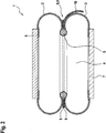
- the Fig. 1 shows a flexible, compressible and designed as a hydraulic lifting cushion 1 for trucks hollow bellows 4 made of elastomeric material, here made of rubber with embedded reinforcing threads / cords.
- the bellows 4 consists of two formed as a fold or bead 2 and 3 bellows parts, which are separated by a metal ring placed around the bellows 5 and thus form two balloon-like right and left of the metal ring 5 outwardly protruding bellows areas.
- the lifting / lifting cushion 1 is formed with base and cover parts, namely formed as a support plate 6 and bottom plate 7, so that the mass to be moved / lifted, here not shown and with a part of its bottom assembly 11 on the support plate 6 launched Truck, can be raised by filling the bellows 4, wherein the bottom plate 7 is positioned on a suitable base 12.
- the filling takes place in this case via not shown supply lines using water as a hydraulic medium.
- annular sliding discs 8 and 9 made of plastic, namely PE-UHMW, arranged as sliding elements, to which the bellows parts can create under load of the lifting cushion.
- PE-UHMW plastic
- the two slidably mounted annular sliding discs 8 and 9 are made of PE-UHMW, an extremely slippery plastic material, which has a significantly lower coefficient of friction in both the friction pairing with itself or with the material of the bellows as the material of the lifting pad in the friction pair with it itself.
- the inner diameter of the sliding discs 8 and 9 is greater than that Outer diameter of a metal ring 5, which is arranged here for stabilization between the adjacent folds or beads 2 and 3.
- Fig. 2 shows an embodiment of the lifting pad 1 according to the invention, in which the annular sliding discs 8 and 9 are formed asymmetrically and made of different plastics.
- the lower sliding washer 9 is a in the Fig. 2 right circular segment formed with a tongue 10 which covers a downwardly extending bellows portions of the bellows air spring. This prevents damage to the bellows 4, if an operation in cramped conditions is necessary.
- Such a flexible, fillable by a flowable medium under pressure hollow bladder of elastomeric material can of course be used as a fixed component, for example in rail vehicles, to adjust the height of the car body or to the car body at stops / stops to the level of Raise or lower platform edge.
- Such built-in components could be filled, for example, with hydraulic oil and be adapted in the dimensions so that the normal height regulation or suspension can be supported.
Landscapes
- Engineering & Computer Science (AREA)
- General Engineering & Computer Science (AREA)
- Mechanical Engineering (AREA)
- Fluid-Damping Devices (AREA)
- Diaphragms And Bellows (AREA)
Abstract
Description
- Die Erfindung betrifft einen flexiblen, durch ein fließfähiges Medium unter Druck befüllbaren hohlen Balg aus elastomerem Material, etwa aus Gummi oder ähnlichen Werkstoffen, insbesondere einen hydraulisch oder pneumatisch betriebenen Aktuator in Form einer Hebevorrichtung oder einer Höheneinstellung für Lasten oder Bauteile, wobei der Balg einen Balgteil oder mehrere, ggf. durch Falten oder Wülste () gebildete benachbarte Balgteile aufweist und mit Hilfe von Anschlussteilen zwischen einer Grundplatte oder Basis und einer Last oder einem Bauteil angeordnet oder befestigt ist, wobei der Balg zwischen den Anschlussteilen ballonartig nach außen hervortritt, ggf. in Form von mehreren Falten oder Wülsten.
- Solche unter Druck befüllbare Bälge sind in Form von als Hubkissen oder Hebevorrichtungen ausgebildeten Aktuatoren vielfach bekannt.
- So offenbart die
DE 37 43 551 A1 ein pneumatisches Hubkissen zum Anheben von Lasten, insbesondere von Kraftfahrzeugen, bestehend aus mehreren, lagenweise übereinanderliegenden, aufblasbaren Einzelelementen aus luftdicht beschiclitetem Polgewebe, bei dem die als Hohlräume ausgebildeten Einzelelemente miteinander in Verbindung stehen und nur ein einziger, allen Einzelelementen gemeinsamer Anschluß für eine Luftzuführung vorgesehen ist. Die als Hohlräume ausgebildeten Einzelelemente treten an ihren Rändern in Form von Falten oder Wülsten nach außen hervor und liegen übereinander in einem Stapel. Beim Heben von Lasten können nachteiligerweise Reibungseffekte bzw. Relativbewegungen zwischen den einzelnen Elementen entstehen, welche letztlich und bei häufigem Betätigen schädigend auf die Wände der Einzelelemente wirken können. - Die
DE PS 918 066 - Die
DE OS 29 00 353 - Die
DE 37 03 593 A1 offenbart eine pneumatische Hubvorrichtung für Flugzeuge und weist ein Flugzeughebekissen auf, das aus mehreren, lagenweise übereinander angeordneten, luftdichten Kammern aufgebaut ist, die jeweils aus Abstandsfadengewebe gefertigt sind und jeweils einen Nippel für einen Luftanschluß haben und ein Steuergerät, das einen Anschluß für eine Fülleitung aufweist, eine der Anzahl der Kammern entsprechende Anzahl von Steuereinheiten für die einzelnen Kammern aufweist, die jeweils ein Steuerventil und einen Kammeranschluß haben, der über eine Schlauchleitung individuell mit der zugehörigen Kammer verbunden werden kann. - All diese Vorrichtungen besitzen den Nachteil, dass unter starker Belastung und unter der Wirkung von Querkräften auf den hohlen Balg oder das Hubkissen, einander benachbarte Wülste oder Falten entweder miteinander in Berührung und damit in einen Reibkontakt geraten oder aber mit anliegenden Anschlussteilen. So kann eine Berührung zwischen benachbarten Wülsten oder Falten insbesondere bei Mehfaltenbälgen oder bei Hubkissen für schwere Hubgüter wie Straßenbahnen oder Schienenfahrzeuge auftreten, die ja eine nur relativ geringe Einsatz- oder Einbauhöhe aufweisen dürfen. Die hier entstehende Reibpaarung kann dazu führen, dass sich die entsprechend in Kontakt stehenden Balgteile stark erwärmen und dann einem erhöhten Reibverschleiß unterworfen sind. Dies kann im Extremfall dazu führen, dass Teile der als Verstärkungselemente in der Balgwand angeordneten Gewebelagen freigelegt werden.
- Für die Erfindung bestand also die Aufgabe, einen durch ein fließfähiges Medium unter Druck befüllbaren hohlen Balg aus elastomerem Material bereitzustellen, insbesondere zur Verwendung als Hubkissen oder Stellelement, bei dem das Problem des erhöhten Reibverschleißes bei hohen Belastungen und Querkräften an benachbarten Teilen/Konstruktionsteilen, Anschlussteilen oder auch Wülsten oder Falten beseitigt wird, der dabei einfach herzustellen ist und keine zusätzlichen Anforderungen an den Bauraum stellt oder größere Aufwendungen von Zusatzteilen verlangt.
- Gelöst wird diese Aufgabe durch die Merkmale des Hauptanspruchs. Weitere vorteilhafte Ausbildungen sind in den Unteransprüchen offenbart.
- Dabei sind zwischen einander benachbarten Balgteilen und/oder zwischen Balgteilen und Anschlussteilen Gleitelemente, insbesondere ringförmige als Gleitscheiben ausgebildete Gleitelemente angeordnet, an die sich die Balgteile bzw. Falten oder Wülste unter oder bei entsprechender Belastung der Balgluftfeder bzw. Faltenbalgluftfeder anlegen. Durch einen stark verringerten Gleitreibungskoeffizienten vermeiden solche Gleitscheiben als Gleitelemente bei relativen Bewegungen der belasteten Wülste gegeneinander oder der Balgteile gegenüber den Anschlussteilen eine Erwärmung und einen entsprechenden Verschleiß des Balgmaterials, bei Gummi einen Abbau der Gummi-Matrix.
- Eine vorteilhafte Weiterbildung besteht aus diesem Grunde auch darin, dass die Gleitelemente/ ringförmigen Gleitscheiben aus einem Material bestehen, vorzugsweise aus gleitfähigem Kunststoffmaterial, welches in der Reibpaarung mit sich selbst oder mit dem Material der Balgluftfeder /Faltenbalgluftfeder einen niedrigeren Reibkoeffizienten aufweist als das Material der Balgluftfeder /Faltenbalgluftfeder in der Reibpaarung mit sich selbst oder mit dem Material der Anschlussteile.
- Bei einer solchen Anordnung gleiten im wesentlichen nur noch die Gleitelement/Gleitscheiben aufeinander, wodurch die Reibung und die damit einhergehende Wärmeentwicklung stark reduziert wird, insbesondere natürlich auch dann, wenn die gleitend aufeinander angeordneten ringförmigen Gleitscheiben oder Gleitelemente aus unterschiedlichen und in ihrer Gleitfähigkeit angepassten Materialien, vorzugsweise aus gleitfähigen Kunststoffmaterialien oder auch aus unterschiedliche gleitfähigen Kunststoffmaterialien bestehen. Solche gleitfähgen Materialien , können zum Beispiel Polytetrafluorethylen (PTFE) oder hochdichtes Polyethylen (ultra-hight density Polyethylene / PE-UHMW) sein. Hierbei kann auch eine Vielzahl von Gleitelementen/Gleitscheiben eingesetzt sein, die einen schädlichen Reibkontakt zwischen den Wülsten oder Falten und einem zur Trennung der Wülsten oder Falten um den Balg gelegten Gürtel oder Stahlring verhindern.
- Eine weitere vorteilhafte Ausbildung besteht darin, dass jeweils entweder mindestens zwei gleitend aufeinander angeordnete ringförmige Gleitscheiben oder mindestens eine Gleitscheibe und ein weiteres deckelförmiges Gleitelement zwischen Balgteilen und Anschlussteilen angeordnet sind, an die sich die Balgteile unter Belastung anlegen. Damit lassen sich insbesondere die Anschlussbereiche, d.h. die Einspannungen des Hubkissens oder Balgs sicher gegen zu hohe Wärmebelastung durch Reibung beim Anlegen der nach außen hervortretenden Balgfalten an die Anschlussteile schützen.
- Eine weitere vorteilhafte Ausbildung besteht darin, dass die gleitend aufeinander angeordneten ringförmigen Gleitscheiben oder Gleitelemente radial gegeneinander oder gegeneinander drehend gleitbeweglich angeordnet sind, so dass auch auf ein Hubkissen oder Balg/Stellbalg einwirkende starke oder gar oszillierende Querkräfte und Drehbewegungen oder ein auf den Balg einwirkende Drehmoment nicht zu
- Wärmebelastungen durch Reibung führen.
- Eine weitere vorteilhafte Ausbildung besteht darin, dass die ringförmigen Gleitscheiben oder Gleitelemente asymmetrisch ausgebildet sind und mindestens in einem Kreissegment weitere Balgbereiche bedecken. Das verhindert z. B. im mittleren Bereich einer Balgwulst, also entfernt von den Anschlussteilen, bei Belastungen ein Anlegen der Balgluftfeder an umgebende Bauteile, beispielsweise andere Fahrwerksbauteile, so dass auch hier keine Wärmebelastung durch Reibung entstehen kann.
- Unterstützt wird die Verminderung unerwünschter Reibung durch weitere vorteilhafte Ausbildungen, die darin bestehen, dass die ringförmigen Gleitscheiben oder Gleitelemente im Querschnitt konkav oder konvex ausgebildet sind und/oder dass die ringförmigen Gleitscheiben oder Gleitelemente so flexibel ausgebildet sind, dass sie sich unter Belastung der Faltenbalgluftfeder an die Balgbereiche anlegen.
- Einsetzen lässt eine solche erfindungsgemäße Balgluftfeder besonders gut als Stellmittel zur Höheneinstellung eines Fahrzeugfahrwerks, insbesondere eines Schienenfahrzeugs oder eines Kraftfahrzeugs verwenden, bei dem hohe statische und dynamische Traglasten und große Querkräfte wirken. Dasselbe gilt für die Verwendung als Stellmittel für die Höheneinstellung von Maschinen oder Vorrichtungen im industriellen Bereich. Natürlich ist der erfindungsgemäße durch ein fließfähiges Medium unter Druck befüllbare hohlen Balg ebenso geeignet als Hubkissen im industriellen Anwendungsbereich geeignet, z.B. zur Montage von Maschinen, zum Heben von Bahnen oder Lokomotiven beim Fahrwerkswechsel etc.
- Anhand eines Ausführungsbeispiels soll die Erfindung näher erläutert werden. Es zieigen
- Fig. 1
- einen flexiblen, unter Druck befüllbaren und als hydraulisches Hubkissen für LKW ausgebildeten erfindungsgemäßen Balg
- Fig. 2
- Eine weitere Ausführung eines Balgs gemäß
Fig. 1 mit angepassten Gleitscheiben - Die
Fig. 1 zeigt einen flexiblen, unter Druck befüllbaren und als hydraulisches Hubkissen 1 für LKW ausgebildeten hohlen Balg 4 aus elastomerem Material, hier aus Gummi mit eingebetteten Verstärkungsfäden/Corden. Der Balg 4 besteht aus zwei als Falte oder Wulst 2 und 3 ausgebildeten Balgteilen, die durch einen um den Balg gelegten Metallring 5 getrennt sind und somit zwei ballonartig rechts und links des Metallrings 5 nach außen hervortretende Balgbereiche bilden. - Die Hebevorrichtung/das Hubkissen 1 ist mit Basis- und Deckelteilen ausgebildet, nämlich ausgebildete als Auflageplatte 6 und Bodenplatte 7, so dass die zu bewegende/zu hebende Masse, hier ein nicht weiter dargestellter und mit einem Teil seiner Bodengruppe 11 auf die Auflageplatte 6 aufgelegter Lkw, durch Befüllung des Balgs 4 angehoben werden kann, wobei die Bodenplatte 7 auf einer geeigneten Unterlage 12 positioniert wird. Die Befüllung erfolgt in diesem Fall über nicht weiter dargestellte Zuleitungen mithilfe von Wasser als hydraulischem Medium.
- Zwischen den einander benachbarten Balgteilen 2 und 3 sind zwei ringförmige Gleitscheiben 8 und 9 aus Kunststoff, nämlich PE-UHMW, als Gleitelemente angeordnet, an die sich die Balgteile unter Belastung des Hubkissens anlegen können. Bei einer entsprechenden Auslegung der Reibpaarung zwischen dem Material des Balgs 4, d.h. zwischen dem Material der Wülste 2, 3 und dem verwendeten Kunststoff, kann es auch ausreichen, dass nur eine Gleitscheibe 8 zwischen die Wülste gelegt wird, die mit ihrer Oberseite an der Wulst 2 anliegt und mit ihrer Unterseite an der Wulst 3.
- Die zwei gleitend aufeinander angeordneten ringförmigen Gleitscheiben 8 und 9 bestehen aus PE-UHMW, einem extrem gleitfähigem Kunststoffmaterial, welches sowohl in der Reibpaarung mit sich selbst oder mit dem Material des Balgs einen wesentlich niedrigeren Reibkoeffizienten aufweist als das Material des Hubkissens in der Reibpaarung mit sich selbst. Der Innendurchmesser der Gleitscheiben 8 und 9 ist dabei größer ist als der Außendurchmesser eines Metallrings 5, der hier zur Stabilisierung zwischen den benachbarten Falten oder Wülsten 2 und 3 angeordnet ist.
-
Fig. 2 zeigt eine Ausführung des erfindungsgemäßen Hubkissens 1, bei der die ringförmigen Gleitscheiben 8 und 9 asymmetrisch und aus unterschiedlichen Kunststoffen ausgebildet sind. Die untere Gleitscheibe 9 ist über ein in derFig. 2 rechts liegendes Kreissegment mit eine Zunge 10 ausgebildet, die einen sich nach unten erstreckenden Balgbereiche der Faltenbalgluftfeder bedeckt. Das verhindert Beschädigungen des Balgs 4, falls ein Einsatz unter beengten Verhältnissen notwendig wird. - Ein solcher flexibler, durch ein fließfähiges Medium unter Druck befüllbarer hohler Balg aus elastomerem Material kann natürlich auch als fest eingebautes Bauteil, beispielsweise in Schienenfahrzeugen, eingesetzt werden, um die Höhe des Wagenkastens einzustellen bzw. um den Wagenkasten an Haltestellen/Haltepunkten auf das Niveau der Bahnsteigkante anzuheben oder abzusenken. Solche fest eingebauten Bauteile könnten zum Beispiel mit Hydrauliköl befüllt werden und in den Abmessungen so angepasst sein, dass die normale Höhenregulierung bzw. Federung damit unterstützt werden kann.
- Auf diese Weise sind mit fest eingebauten unter Druck befüllbarer hohlen Bälgen aus elastomerem Material auch weitere Anwendungen denkbar, etwa in der Höhenjustierung von LKW-Ladeflächen oder Lkw-Anhängern.
- Natürlich lassen sich auch, bei etwas andere Befestigungssituation zwischen Auflageplatte 6, Bodenplatte 7 und dem Balg 4 bzw. den Wülsten 2 und 3, solche Gleitscheiben zwischen den Wülsten 2, 3 und den entsprechenden Anschlussteilen, d.h. Auflageplatte und Bodenplatte anordnen.
-
- 1
- Hubkissen
- 2
- Wulst/Falte
- 3
- Wulst/Falte
- 4
- Hohler Balg
- 5
- Metallring/Trennring
- 6
- Auflageplatte
- 7
- Bodenplatte
- 8
- Gleitscheibe/Gleitelement
- 9
- Gleitscheibe/Gleitelement
- 10
- Zunge an der Gleitscheibe
- 11
- Bodengruppe eines LKW
- 12
- Unterlage
Claims (10)
- Flexibler, durch ein fließfähiges Medium unter Druck befüllbarer hohler Balg (4) aus elastomerem Material, insbesondere hydraulisch oder pneumatisch betriebener Aktuator in Form einer Hebevorrichtung (1) oder einer Höheneinstellung für Lasten oder Bauteile , wobei der Balg einen Balgteil oder mehrere, ggf. durch Falten oder Wülste (2, 3) gebildete benachbarte Balgteile aufweist und mit Hilfe von Anschlussteilen zwischen einer Grund- bzw. Bodenplatte (12) und einer Last oder einem Bauteil (11) angeordnet oder befestigt ist, wobei der Balg (4) zwischen den Anschlussteilen, ggf. in Form von Falten oder Wülsten (2, 3), ballonartig nach außen hervortritt, dadurch gekennzeichnet, dass zwischen einander benachbarten Balgteilen und/oder zwischen Balgteilen und Anschlussteilen ringförmige Gleitelemente (8, 9), insbesondere als Gleitscheiben ausgebildete Gleitelemente angeordnet sind, an die sich die Balgteile bzw. Falten oder Wülste unter Belastung der Faltenbalgluftfeder anlegen.
- Flexibler Balg nach Anspruch 1, bei dem die ballonartig nach außen hervortretenden Falten oder Wülsten (2, 3) durch einen um den Balg gelegten und die Falten oder Wülste trennenden Gürtel oder Ring (5) ausgebildet werden.
- Flexibler Balg nach Anspruch 1 oder 2, bei dem die Gleitelemente oder ringförmigen Gleitscheiben (8, 9) aus einem Material bestehen, vorzugsweise aus gleitfähigem Kunststoffmaterial, welches in der Reibpaarung mit sich selbst oder mit dem Material der Balgluftfeder einen niedrigeren Reibkoeffizienten aufweist als das Material der Balgluftfeder in der Reibpaarung mit sich selbst oder mit dem Material der Anschlussteile.
- Flexibler Balg nach einem der Ansprüche 1 bis 3, ausgebildet als hydraulisches oder pneumatisches Hubkissen oder Stellelement (1), bei dem jeweils mindestens zwei gleitend aufeinander angeordnete ringförmige Gleitscheiben (8, 9) zwischen benachbarten Falten oder Wülsten angeordnet sind, die sich unter Belastung aneinander anlegen.
- Flexibler Balg nach einem der Ansprüche 1 bis 4, bei der jeweils entweder mindestens zwei gleitend aufeinander angeordnete ringförmige Gleitscheiben zwischen Balgteilen und Anschlussteilen angeordnet sind, an die sich die Balgteile unter Belastung der Faltenbalgluftfeder anlegen.
- Flexibler Balg nach Anspruch 4 oder 5, bei der die gleitend aufeinander angeordneten ringförmigen Gleitscheiben oder Gleitelemente (8, 9) radial gegeneinander oder gegeneinander drehend gleitbeweglich angeordnet sind.
- Flexibler Balg nach einem der Ansprüche 4 bis 6, bei der die gleitend aufeinander angeordneten ringförmigen Gleitscheiben oder Gleitelemente (8, 9) aus unterschiedlichen Materialien, vorzugsweise aus unterschiedlichen gleitfähigen Kunststoffmaterialien bestehen.
- Flexibler Balg nach einem der Ansprüche 1 bis 7, bei der die ringförmigen Gleitscheiben oder Gleitelemente (8, 9) asymmetrisch ausgebildet sind und mindestens in einem Kreissegment durch eine Zunge (10) weitere Balgbereiche bedecken.
- Flexibler Balg nach einem der Ansprüche 1 bis 8, bei der die ringförmigen Gleitscheiben oder Gleitelemente (8, 9) im Querschnitt konkav oder konvex ausgebildet sind.
- Verwendung eines flexiblen Balgs nach einem der Ansprüche 1 bis 9 zur Höheneinstellung eines Fahrzeugfahrwerks, insbesondere eines Schienenfahrzeugs oder eines Kraftfahrzeugs.
Priority Applications (1)
| Application Number | Priority Date | Filing Date | Title |
|---|---|---|---|
| EP14290376.4A EP3032134B1 (de) | 2014-12-10 | 2014-12-10 | Befüllbarer balg aus elastomerem material |
Applications Claiming Priority (1)
| Application Number | Priority Date | Filing Date | Title |
|---|---|---|---|
| EP14290376.4A EP3032134B1 (de) | 2014-12-10 | 2014-12-10 | Befüllbarer balg aus elastomerem material |
Publications (2)
| Publication Number | Publication Date |
|---|---|
| EP3032134A1 true EP3032134A1 (de) | 2016-06-15 |
| EP3032134B1 EP3032134B1 (de) | 2019-06-05 |
Family
ID=52146381
Family Applications (1)
| Application Number | Title | Priority Date | Filing Date |
|---|---|---|---|
| EP14290376.4A Active EP3032134B1 (de) | 2014-12-10 | 2014-12-10 | Befüllbarer balg aus elastomerem material |
Country Status (1)
| Country | Link |
|---|---|
| EP (1) | EP3032134B1 (de) |
Cited By (1)
| Publication number | Priority date | Publication date | Assignee | Title |
|---|---|---|---|---|
| CN106763411A (zh) * | 2016-11-09 | 2017-05-31 | 上海卫星装备研究所 | 一种用于航天器在轨失重环境模拟的隔振装置 |
Citations (5)
| Publication number | Priority date | Publication date | Assignee | Title |
|---|---|---|---|---|
| GB258893A (en) * | 1925-09-24 | 1927-04-14 | Carlo Rigotti | Improvements in and relating to pneumatic springs |
| US2893665A (en) * | 1953-04-25 | 1959-07-07 | Luxembourg Brev Participations | Resilient suspension devices |
| DE1914391U (de) * | 1964-02-18 | 1965-04-22 | Gomma Antivibranti Applic | Balgluftfeder. |
| JPS56153134A (en) * | 1980-04-30 | 1981-11-27 | Bridgestone Corp | Air spring |
| US4832317A (en) * | 1982-03-11 | 1989-05-23 | Dunlop Limited A British Company | Fluid pressure devices |
-
2014
- 2014-12-10 EP EP14290376.4A patent/EP3032134B1/de active Active
Patent Citations (5)
| Publication number | Priority date | Publication date | Assignee | Title |
|---|---|---|---|---|
| GB258893A (en) * | 1925-09-24 | 1927-04-14 | Carlo Rigotti | Improvements in and relating to pneumatic springs |
| US2893665A (en) * | 1953-04-25 | 1959-07-07 | Luxembourg Brev Participations | Resilient suspension devices |
| DE1914391U (de) * | 1964-02-18 | 1965-04-22 | Gomma Antivibranti Applic | Balgluftfeder. |
| JPS56153134A (en) * | 1980-04-30 | 1981-11-27 | Bridgestone Corp | Air spring |
| US4832317A (en) * | 1982-03-11 | 1989-05-23 | Dunlop Limited A British Company | Fluid pressure devices |
Cited By (1)
| Publication number | Priority date | Publication date | Assignee | Title |
|---|---|---|---|---|
| CN106763411A (zh) * | 2016-11-09 | 2017-05-31 | 上海卫星装备研究所 | 一种用于航天器在轨失重环境模拟的隔振装置 |
Also Published As
| Publication number | Publication date |
|---|---|
| EP3032134B1 (de) | 2019-06-05 |
Similar Documents
| Publication | Publication Date | Title |
|---|---|---|
| EP2539603B1 (de) | Belüfteter luftbalg für eine luftfeder, einen belüfteten luftbalg enthaltende luftfeder sowie belüftete luftbälge enthaltendes luftfedersystem | |
| EP2605923B1 (de) | Luftfederbein mit elastischer kolbenlagerung | |
| DE2200978A1 (de) | Zusammengesetzte elastische Traglager | |
| WO2015165910A2 (de) | Schwingungsdämpfer eines fahrzeug-rads | |
| DE102007050084A1 (de) | Abstützung für eine Schraubendruckfeder | |
| EP2847487B1 (de) | Luftfeder und verfahren zum umschlagen eines luftfederbalges einer luftfeder | |
| DE1060722B (de) | Vorrichtung zum Verhueten des Schlingerns von Fahrzeugen | |
| WO2017097558A1 (de) | Gummi-metall-federelement | |
| EP3050725B1 (de) | Blockierungsvorrichtung für Fahrzeugfederungen | |
| DE2140124C2 (de) | Elastische Lagerbüchse | |
| DE102012007709B4 (de) | Gummi-Metall-Konuslager mit stufenförmiger Axialfederkennlinie | |
| DE102011086415A1 (de) | Elastisch gelagerter Luftfederabrollkolben | |
| DE102011086909A1 (de) | Luftfederbein für ein Fahrzeug | |
| EP3032134B1 (de) | Befüllbarer balg aus elastomerem material | |
| DE102015013605B4 (de) | Niveauregulierung | |
| WO2015139854A1 (de) | Kältefeste luftfedereinrichtung | |
| EP2180204B1 (de) | Zusatzfeder mit Gleitfläche | |
| EP2863087B1 (de) | Luftfeder mit Gleitelement | |
| EP2353962A1 (de) | Fahrwerksanordnung für ein Schienenfahrzeug | |
| WO2010009884A1 (de) | An einem führungsholm einer scheibenbremse angeordneter faltenbalg | |
| EP2708387B1 (de) | Lager | |
| DE1290436B (de) | Vorrichtung zur Begrenzung eines Stroemungsmittelkissens fuer eine Stroemungsmittelkissenmaschine | |
| DE102015010314B4 (de) | Arretierungsanordnung | |
| DE102019212624B3 (de) | Zusätzlich absenkbare Fahrwerksfederung | |
| EP3032133B1 (de) | Faltenbalgluftfeder mit Abstandsring |
Legal Events
| Date | Code | Title | Description |
|---|---|---|---|
| PUAI | Public reference made under article 153(3) epc to a published international application that has entered the european phase |
Free format text: ORIGINAL CODE: 0009012 |
|
| 17P | Request for examination filed |
Effective date: 20141219 |
|
| AK | Designated contracting states |
Kind code of ref document: A1 Designated state(s): AL AT BE BG CH CY CZ DE DK EE ES FI FR GB GR HR HU IE IS IT LI LT LU LV MC MK MT NL NO PL PT RO RS SE SI SK SM TR |
|
| AX | Request for extension of the european patent |
Extension state: BA ME |
|
| RBV | Designated contracting states (corrected) |
Designated state(s): AL AT BE BG CH CY CZ DE DK EE ES FI FR GB GR HR HU IE IS IT LI LT LU LV MC MK MT NL NO PL PT RO RS SE SI SK SM TR |
|
| GRAP | Despatch of communication of intention to grant a patent |
Free format text: ORIGINAL CODE: EPIDOSNIGR1 |
|
| STAA | Information on the status of an ep patent application or granted ep patent |
Free format text: STATUS: GRANT OF PATENT IS INTENDED |
|
| INTG | Intention to grant announced |
Effective date: 20190118 |
|
| GRAS | Grant fee paid |
Free format text: ORIGINAL CODE: EPIDOSNIGR3 |
|
| GRAA | (expected) grant |
Free format text: ORIGINAL CODE: 0009210 |
|
| STAA | Information on the status of an ep patent application or granted ep patent |
Free format text: STATUS: THE PATENT HAS BEEN GRANTED |
|
| AK | Designated contracting states |
Kind code of ref document: B1 Designated state(s): AL AT BE BG CH CY CZ DE DK EE ES FI FR GB GR HR HU IE IS IT LI LT LU LV MC MK MT NL NO PL PT RO RS SE SI SK SM TR |
|
| REG | Reference to a national code |
Ref country code: GB Ref legal event code: FG4D Free format text: NOT ENGLISH |
|
| REG | Reference to a national code |
Ref country code: CH Ref legal event code: EP |
|
| REG | Reference to a national code |
Ref country code: AT Ref legal event code: REF Ref document number: 1140300 Country of ref document: AT Kind code of ref document: T Effective date: 20190615 |
|
| REG | Reference to a national code |
Ref country code: IE Ref legal event code: FG4D Free format text: LANGUAGE OF EP DOCUMENT: GERMAN |
|
| REG | Reference to a national code |
Ref country code: DE Ref legal event code: R096 Ref document number: 502014011846 Country of ref document: DE |
|
| REG | Reference to a national code |
Ref country code: NL Ref legal event code: MP Effective date: 20190605 |
|
| REG | Reference to a national code |
Ref country code: LT Ref legal event code: MG4D |
|
| PG25 | Lapsed in a contracting state [announced via postgrant information from national office to epo] |
Ref country code: SE Free format text: LAPSE BECAUSE OF FAILURE TO SUBMIT A TRANSLATION OF THE DESCRIPTION OR TO PAY THE FEE WITHIN THE PRESCRIBED TIME-LIMIT Effective date: 20190605 Ref country code: HR Free format text: LAPSE BECAUSE OF FAILURE TO SUBMIT A TRANSLATION OF THE DESCRIPTION OR TO PAY THE FEE WITHIN THE PRESCRIBED TIME-LIMIT Effective date: 20190605 Ref country code: ES Free format text: LAPSE BECAUSE OF FAILURE TO SUBMIT A TRANSLATION OF THE DESCRIPTION OR TO PAY THE FEE WITHIN THE PRESCRIBED TIME-LIMIT Effective date: 20190605 Ref country code: LT Free format text: LAPSE BECAUSE OF FAILURE TO SUBMIT A TRANSLATION OF THE DESCRIPTION OR TO PAY THE FEE WITHIN THE PRESCRIBED TIME-LIMIT Effective date: 20190605 Ref country code: NO Free format text: LAPSE BECAUSE OF FAILURE TO SUBMIT A TRANSLATION OF THE DESCRIPTION OR TO PAY THE FEE WITHIN THE PRESCRIBED TIME-LIMIT Effective date: 20190905 Ref country code: AL Free format text: LAPSE BECAUSE OF FAILURE TO SUBMIT A TRANSLATION OF THE DESCRIPTION OR TO PAY THE FEE WITHIN THE PRESCRIBED TIME-LIMIT Effective date: 20190605 Ref country code: FI Free format text: LAPSE BECAUSE OF FAILURE TO SUBMIT A TRANSLATION OF THE DESCRIPTION OR TO PAY THE FEE WITHIN THE PRESCRIBED TIME-LIMIT Effective date: 20190605 |
|
| PG25 | Lapsed in a contracting state [announced via postgrant information from national office to epo] |
Ref country code: GR Free format text: LAPSE BECAUSE OF FAILURE TO SUBMIT A TRANSLATION OF THE DESCRIPTION OR TO PAY THE FEE WITHIN THE PRESCRIBED TIME-LIMIT Effective date: 20190906 Ref country code: BG Free format text: LAPSE BECAUSE OF FAILURE TO SUBMIT A TRANSLATION OF THE DESCRIPTION OR TO PAY THE FEE WITHIN THE PRESCRIBED TIME-LIMIT Effective date: 20190905 Ref country code: LV Free format text: LAPSE BECAUSE OF FAILURE TO SUBMIT A TRANSLATION OF THE DESCRIPTION OR TO PAY THE FEE WITHIN THE PRESCRIBED TIME-LIMIT Effective date: 20190605 Ref country code: RS Free format text: LAPSE BECAUSE OF FAILURE TO SUBMIT A TRANSLATION OF THE DESCRIPTION OR TO PAY THE FEE WITHIN THE PRESCRIBED TIME-LIMIT Effective date: 20190605 |
|
| PG25 | Lapsed in a contracting state [announced via postgrant information from national office to epo] |
Ref country code: NL Free format text: LAPSE BECAUSE OF FAILURE TO SUBMIT A TRANSLATION OF THE DESCRIPTION OR TO PAY THE FEE WITHIN THE PRESCRIBED TIME-LIMIT Effective date: 20190605 Ref country code: SK Free format text: LAPSE BECAUSE OF FAILURE TO SUBMIT A TRANSLATION OF THE DESCRIPTION OR TO PAY THE FEE WITHIN THE PRESCRIBED TIME-LIMIT Effective date: 20190605 Ref country code: PT Free format text: LAPSE BECAUSE OF FAILURE TO SUBMIT A TRANSLATION OF THE DESCRIPTION OR TO PAY THE FEE WITHIN THE PRESCRIBED TIME-LIMIT Effective date: 20191007 Ref country code: RO Free format text: LAPSE BECAUSE OF FAILURE TO SUBMIT A TRANSLATION OF THE DESCRIPTION OR TO PAY THE FEE WITHIN THE PRESCRIBED TIME-LIMIT Effective date: 20190605 Ref country code: CZ Free format text: LAPSE BECAUSE OF FAILURE TO SUBMIT A TRANSLATION OF THE DESCRIPTION OR TO PAY THE FEE WITHIN THE PRESCRIBED TIME-LIMIT Effective date: 20190605 Ref country code: EE Free format text: LAPSE BECAUSE OF FAILURE TO SUBMIT A TRANSLATION OF THE DESCRIPTION OR TO PAY THE FEE WITHIN THE PRESCRIBED TIME-LIMIT Effective date: 20190605 |
|
| PG25 | Lapsed in a contracting state [announced via postgrant information from national office to epo] |
Ref country code: IS Free format text: LAPSE BECAUSE OF FAILURE TO SUBMIT A TRANSLATION OF THE DESCRIPTION OR TO PAY THE FEE WITHIN THE PRESCRIBED TIME-LIMIT Effective date: 20191005 Ref country code: SM Free format text: LAPSE BECAUSE OF FAILURE TO SUBMIT A TRANSLATION OF THE DESCRIPTION OR TO PAY THE FEE WITHIN THE PRESCRIBED TIME-LIMIT Effective date: 20190605 Ref country code: IT Free format text: LAPSE BECAUSE OF FAILURE TO SUBMIT A TRANSLATION OF THE DESCRIPTION OR TO PAY THE FEE WITHIN THE PRESCRIBED TIME-LIMIT Effective date: 20190605 |
|
| REG | Reference to a national code |
Ref country code: DE Ref legal event code: R097 Ref document number: 502014011846 Country of ref document: DE |
|
| PG25 | Lapsed in a contracting state [announced via postgrant information from national office to epo] |
Ref country code: TR Free format text: LAPSE BECAUSE OF FAILURE TO SUBMIT A TRANSLATION OF THE DESCRIPTION OR TO PAY THE FEE WITHIN THE PRESCRIBED TIME-LIMIT Effective date: 20190605 |
|
| PLBE | No opposition filed within time limit |
Free format text: ORIGINAL CODE: 0009261 |
|
| STAA | Information on the status of an ep patent application or granted ep patent |
Free format text: STATUS: NO OPPOSITION FILED WITHIN TIME LIMIT |
|
| PG25 | Lapsed in a contracting state [announced via postgrant information from national office to epo] |
Ref country code: DK Free format text: LAPSE BECAUSE OF FAILURE TO SUBMIT A TRANSLATION OF THE DESCRIPTION OR TO PAY THE FEE WITHIN THE PRESCRIBED TIME-LIMIT Effective date: 20190605 Ref country code: PL Free format text: LAPSE BECAUSE OF FAILURE TO SUBMIT A TRANSLATION OF THE DESCRIPTION OR TO PAY THE FEE WITHIN THE PRESCRIBED TIME-LIMIT Effective date: 20190605 |
|
| 26N | No opposition filed |
Effective date: 20200306 |
|
| PG25 | Lapsed in a contracting state [announced via postgrant information from national office to epo] |
Ref country code: SI Free format text: LAPSE BECAUSE OF FAILURE TO SUBMIT A TRANSLATION OF THE DESCRIPTION OR TO PAY THE FEE WITHIN THE PRESCRIBED TIME-LIMIT Effective date: 20190605 |
|
| REG | Reference to a national code |
Ref country code: CH Ref legal event code: PL |
|
| REG | Reference to a national code |
Ref country code: BE Ref legal event code: MM Effective date: 20191231 |
|
| PG25 | Lapsed in a contracting state [announced via postgrant information from national office to epo] |
Ref country code: MC Free format text: LAPSE BECAUSE OF FAILURE TO SUBMIT A TRANSLATION OF THE DESCRIPTION OR TO PAY THE FEE WITHIN THE PRESCRIBED TIME-LIMIT Effective date: 20190605 |
|
| PG25 | Lapsed in a contracting state [announced via postgrant information from national office to epo] |
Ref country code: LU Free format text: LAPSE BECAUSE OF NON-PAYMENT OF DUE FEES Effective date: 20191210 Ref country code: IE Free format text: LAPSE BECAUSE OF NON-PAYMENT OF DUE FEES Effective date: 20191210 |
|
| PG25 | Lapsed in a contracting state [announced via postgrant information from national office to epo] |
Ref country code: LI Free format text: LAPSE BECAUSE OF NON-PAYMENT OF DUE FEES Effective date: 20191231 Ref country code: CH Free format text: LAPSE BECAUSE OF NON-PAYMENT OF DUE FEES Effective date: 20191231 Ref country code: BE Free format text: LAPSE BECAUSE OF NON-PAYMENT OF DUE FEES Effective date: 20191231 |
|
| REG | Reference to a national code |
Ref country code: AT Ref legal event code: MM01 Ref document number: 1140300 Country of ref document: AT Kind code of ref document: T Effective date: 20191210 |
|
| PG25 | Lapsed in a contracting state [announced via postgrant information from national office to epo] |
Ref country code: CY Free format text: LAPSE BECAUSE OF FAILURE TO SUBMIT A TRANSLATION OF THE DESCRIPTION OR TO PAY THE FEE WITHIN THE PRESCRIBED TIME-LIMIT Effective date: 20190605 Ref country code: AT Free format text: LAPSE BECAUSE OF NON-PAYMENT OF DUE FEES Effective date: 20191210 |
|
| PG25 | Lapsed in a contracting state [announced via postgrant information from national office to epo] |
Ref country code: MT Free format text: LAPSE BECAUSE OF FAILURE TO SUBMIT A TRANSLATION OF THE DESCRIPTION OR TO PAY THE FEE WITHIN THE PRESCRIBED TIME-LIMIT Effective date: 20190605 Ref country code: HU Free format text: LAPSE BECAUSE OF FAILURE TO SUBMIT A TRANSLATION OF THE DESCRIPTION OR TO PAY THE FEE WITHIN THE PRESCRIBED TIME-LIMIT; INVALID AB INITIO Effective date: 20141210 |
|
| PG25 | Lapsed in a contracting state [announced via postgrant information from national office to epo] |
Ref country code: MK Free format text: LAPSE BECAUSE OF FAILURE TO SUBMIT A TRANSLATION OF THE DESCRIPTION OR TO PAY THE FEE WITHIN THE PRESCRIBED TIME-LIMIT Effective date: 20190605 |
|
| PGFP | Annual fee paid to national office [announced via postgrant information from national office to epo] |
Ref country code: GB Payment date: 20251219 Year of fee payment: 12 |
|
| PGFP | Annual fee paid to national office [announced via postgrant information from national office to epo] |
Ref country code: FR Payment date: 20251223 Year of fee payment: 12 |
|
| PGFP | Annual fee paid to national office [announced via postgrant information from national office to epo] |
Ref country code: DE Payment date: 20251231 Year of fee payment: 12 |