EP3032169A2 - Dispositif de lampe - Google Patents
Dispositif de lampe Download PDFInfo
- Publication number
- EP3032169A2 EP3032169A2 EP15191319.1A EP15191319A EP3032169A2 EP 3032169 A2 EP3032169 A2 EP 3032169A2 EP 15191319 A EP15191319 A EP 15191319A EP 3032169 A2 EP3032169 A2 EP 3032169A2
- Authority
- EP
- European Patent Office
- Prior art keywords
- plate
- lamp device
- mounting seat
- heat dissipating
- seat
- Prior art date
- Legal status (The legal status is an assumption and is not a legal conclusion. Google has not performed a legal analysis and makes no representation as to the accuracy of the status listed.)
- Withdrawn
Links
Images





Classifications
-
- G—PHYSICS
- G02—OPTICS
- G02B—OPTICAL ELEMENTS, SYSTEMS OR APPARATUS
- G02B6/00—Light guides; Structural details of arrangements comprising light guides and other optical elements, e.g. couplings
- G02B6/0001—Light guides; Structural details of arrangements comprising light guides and other optical elements, e.g. couplings specially adapted for lighting devices or systems
- G02B6/0011—Light guides; Structural details of arrangements comprising light guides and other optical elements, e.g. couplings specially adapted for lighting devices or systems the light guides being planar or of plate-like form
- G02B6/0081—Mechanical or electrical aspects of the light guide and light source in the lighting device peculiar to the adaptation to planar light guides, e.g. concerning packaging
- G02B6/0086—Positioning aspects
- G02B6/0091—Positioning aspects of the light source relative to the light guide
-
- G—PHYSICS
- G02—OPTICS
- G02B—OPTICAL ELEMENTS, SYSTEMS OR APPARATUS
- G02B6/00—Light guides; Structural details of arrangements comprising light guides and other optical elements, e.g. couplings
- G02B6/0001—Light guides; Structural details of arrangements comprising light guides and other optical elements, e.g. couplings specially adapted for lighting devices or systems
- G02B6/0011—Light guides; Structural details of arrangements comprising light guides and other optical elements, e.g. couplings specially adapted for lighting devices or systems the light guides being planar or of plate-like form
- G02B6/0081—Mechanical or electrical aspects of the light guide and light source in the lighting device peculiar to the adaptation to planar light guides, e.g. concerning packaging
- G02B6/0085—Means for removing heat created by the light source from the package
-
- F—MECHANICAL ENGINEERING; LIGHTING; HEATING; WEAPONS; BLASTING
- F21—LIGHTING
- F21K—NON-ELECTRIC LIGHT SOURCES USING LUMINESCENCE; LIGHT SOURCES USING ELECTROCHEMILUMINESCENCE; LIGHT SOURCES USING CHARGES OF COMBUSTIBLE MATERIAL; LIGHT SOURCES USING SEMICONDUCTOR DEVICES AS LIGHT-GENERATING ELEMENTS; LIGHT SOURCES NOT OTHERWISE PROVIDED FOR
- F21K9/00—Light sources using semiconductor devices as light-generating elements, e.g. using light-emitting diodes [LED] or lasers
- F21K9/60—Optical arrangements integrated in the light source, e.g. for improving the colour rendering index or the light extraction
- F21K9/61—Optical arrangements integrated in the light source, e.g. for improving the colour rendering index or the light extraction using light guides
-
- F—MECHANICAL ENGINEERING; LIGHTING; HEATING; WEAPONS; BLASTING
- F21—LIGHTING
- F21V—FUNCTIONAL FEATURES OR DETAILS OF LIGHTING DEVICES OR SYSTEMS THEREOF; STRUCTURAL COMBINATIONS OF LIGHTING DEVICES WITH OTHER ARTICLES, NOT OTHERWISE PROVIDED FOR
- F21V17/00—Fastening of component parts of lighting devices, e.g. shades, globes, refractors, reflectors, filters, screens, grids or protective cages
- F21V17/10—Fastening of component parts of lighting devices, e.g. shades, globes, refractors, reflectors, filters, screens, grids or protective cages characterised by specific fastening means or way of fastening
- F21V17/16—Fastening of component parts of lighting devices, e.g. shades, globes, refractors, reflectors, filters, screens, grids or protective cages characterised by specific fastening means or way of fastening by deformation of parts; Snap action mounting
- F21V17/164—Fastening of component parts of lighting devices, e.g. shades, globes, refractors, reflectors, filters, screens, grids or protective cages characterised by specific fastening means or way of fastening by deformation of parts; Snap action mounting the parts being subjected to bending, e.g. snap joints
-
- F—MECHANICAL ENGINEERING; LIGHTING; HEATING; WEAPONS; BLASTING
- F21—LIGHTING
- F21V—FUNCTIONAL FEATURES OR DETAILS OF LIGHTING DEVICES OR SYSTEMS THEREOF; STRUCTURAL COMBINATIONS OF LIGHTING DEVICES WITH OTHER ARTICLES, NOT OTHERWISE PROVIDED FOR
- F21V19/00—Fastening of light sources or lamp holders
- F21V19/001—Fastening of light sources or lamp holders the light sources being semiconductors devices, e.g. LEDs
-
- G—PHYSICS
- G02—OPTICS
- G02B—OPTICAL ELEMENTS, SYSTEMS OR APPARATUS
- G02B6/00—Light guides; Structural details of arrangements comprising light guides and other optical elements, e.g. couplings
- G02B6/0001—Light guides; Structural details of arrangements comprising light guides and other optical elements, e.g. couplings specially adapted for lighting devices or systems
- G02B6/0011—Light guides; Structural details of arrangements comprising light guides and other optical elements, e.g. couplings specially adapted for lighting devices or systems the light guides being planar or of plate-like form
- G02B6/0066—Light guides; Structural details of arrangements comprising light guides and other optical elements, e.g. couplings specially adapted for lighting devices or systems the light guides being planar or of plate-like form characterised by the light source being coupled to the light guide
- G02B6/0068—Arrangements of plural sources, e.g. multi-colour light sources
-
- G—PHYSICS
- G02—OPTICS
- G02B—OPTICAL ELEMENTS, SYSTEMS OR APPARATUS
- G02B6/00—Light guides; Structural details of arrangements comprising light guides and other optical elements, e.g. couplings
- G02B6/0001—Light guides; Structural details of arrangements comprising light guides and other optical elements, e.g. couplings specially adapted for lighting devices or systems
- G02B6/0011—Light guides; Structural details of arrangements comprising light guides and other optical elements, e.g. couplings specially adapted for lighting devices or systems the light guides being planar or of plate-like form
- G02B6/0081—Mechanical or electrical aspects of the light guide and light source in the lighting device peculiar to the adaptation to planar light guides, e.g. concerning packaging
- G02B6/0086—Positioning aspects
- G02B6/009—Positioning aspects of the light source in the package
-
- F—MECHANICAL ENGINEERING; LIGHTING; HEATING; WEAPONS; BLASTING
- F21—LIGHTING
- F21Y—INDEXING SCHEME ASSOCIATED WITH SUBCLASSES F21K, F21L, F21S and F21V, RELATING TO THE FORM OR THE KIND OF THE LIGHT SOURCES OR OF THE COLOUR OF THE LIGHT EMITTED
- F21Y2101/00—Point-like light sources
-
- G—PHYSICS
- G02—OPTICS
- G02B—OPTICAL ELEMENTS, SYSTEMS OR APPARATUS
- G02B6/00—Light guides; Structural details of arrangements comprising light guides and other optical elements, e.g. couplings
- G02B6/0001—Light guides; Structural details of arrangements comprising light guides and other optical elements, e.g. couplings specially adapted for lighting devices or systems
- G02B6/0011—Light guides; Structural details of arrangements comprising light guides and other optical elements, e.g. couplings specially adapted for lighting devices or systems the light guides being planar or of plate-like form
- G02B6/0013—Means for improving the coupling-in of light from the light source into the light guide
- G02B6/0023—Means for improving the coupling-in of light from the light source into the light guide provided by one optical element, or plurality thereof, placed between the light guide and the light source, or around the light source
- G02B6/0031—Reflecting element, sheet or layer
-
- G—PHYSICS
- G02—OPTICS
- G02B—OPTICAL ELEMENTS, SYSTEMS OR APPARATUS
- G02B6/00—Light guides; Structural details of arrangements comprising light guides and other optical elements, e.g. couplings
- G02B6/0001—Light guides; Structural details of arrangements comprising light guides and other optical elements, e.g. couplings specially adapted for lighting devices or systems
- G02B6/0011—Light guides; Structural details of arrangements comprising light guides and other optical elements, e.g. couplings specially adapted for lighting devices or systems the light guides being planar or of plate-like form
- G02B6/0081—Mechanical or electrical aspects of the light guide and light source in the lighting device peculiar to the adaptation to planar light guides, e.g. concerning packaging
- G02B6/0086—Positioning aspects
- G02B6/0088—Positioning aspects of the light guide or other optical sheets in the package
Definitions
- the disclosure relates to a lighting tool, and more particularly to a lamp device that is easy to assemble.
- a conventional light-emitting diode (LED) lamp device 1 includes a heat dissipating seat 11 defining an accommodation space 10, a light emitting unit 12 accommodated in the accommodation space 10, a light guide plate 13 accommodated in the accommodation space 10 spaced apart from the light emitting unit 12, a reflecting unit 14 disposed in the accommodation space 10 and matching in position with the light guide plate 13, and a fixing unit 15 disposed in the accommodation space 10 for fixing the light guide plate 13.
- LED light-emitting diode
- the heat dissipating seat 11 includes first and second assembly members 111, 112 that are joined together and that cooperate with each other to divide the accommodation space 10 into a first mounting area 101 for receiving the light emitting unit 12, and a second mounting area 102 spaced apart from the first mounting area 101 for receiving the light guide plate 13 therethrough.
- the light guide plate 13 is sandwiched between the first and second assembly members 111, 112, and divides the second mounting area 102 into two filling portions 103, each of which is defined between the light guide plate 13 and a corresponding one of the first and second assembly members 111, 112.
- the light emitting unit 12 includes a circuit board 121 fixed to the first assembly member 111 within the first mounting area 101, and at least one light-emitting diode 122 fixed to the circuit board 121.
- the reflecting unit 14 includes two reflecting pieces 141 respectively mounted in the filling portions 103.
- the fixing unit 15 includes a fixing member 151 disposed in the second mounting area 102 and penetrates the light guide plate 13, and two fillers 152 respectively disposed in the remaining spaces of the filling portions 103 below the reflecting pieces 141.
- the light emitting unit 12 is first fixed to the first assembly member 111 of the heat dissipating seat 11 by using an adhesive or a fastener.
- the light guide plate 13, the reflecting pieces 141 and the fillers 152 are then disposed in their corresponding specific locations, followed by mutual engagement of the first and second assembly members 111, 112, thereby completing the assembly process.
- the conventional LED lamp device 1 has many components, and since the assembly of the components thereof is complicated and must rely on experience and proficiency for quick assembly, the cost of the conventional LED lamp device 1 is high, and the assembly process thereof is time-consuming and prone to failure.
- an object of the disclosure is to provide a lamp device that can alleviate at least one of the drawbacks of the prior art.
- a lamp device includes a light emitting unit having at least one light source, a mounting seat covering the light emitting unit, a receiving space defined by at least a portion of the mounting seat and extending in a direction away from the light emitting unit, and a light guide plate having at least a portion inserted into and fixed within the receiving space.
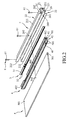
- the first embodiment of a lamp device includes a heat dissipating seat 2, a light emitting unit 3, a mounting seat 4, a light guide plate 5, and a fixing unit 6 to assist in the assembly of the lamp device.
- the heat dissipating seat 2 defines an accommodation space 20 with an opening 200.
- the light emitting unit 3 is fixed to the heat dissipating seat 2 within the accommodation space 20.
- the mounting seat 4 is disposed in the accommodation space 20 through the opening 200, and covers the light emitting unit 3.
- the mounting seat 4 defines a receiving space 40 that is opposite to the light emitting unit 3.
- the light guide plate 5 has a portion inserted into and fixed within the receiving space 40.
- the fixing unit 6 includes a plurality of fixing members 61, such as screws or bolts, for fixing the portion of the light guide plate 5 within the receiving space 40.
- the light guide plate 5 is substantially rectangular, and has two concave grooves 501 extending inwardly and respectively from two opposite short sides thereof, and an orifice 502 is configured between the concave grooves 501.
- the concave grooves 501 and the orifice 502 are provided for the fixing members 61 to pass respectively therethrough. It should be noted herein that the light guide plate 5 may be formed with a plurality of orifices 502, so that more fixing members 61 may be used to fix the light guide plate 5 in the receiving space 40.
- the heat dissipating seat 2 includes a base plate 21, and two lateral members 22 respectively connected to two opposite ends of the base plate 21 and cooperating with the base plate 21 to define the accommodation space 20.
- Each of the lateral members 22 includes a lateral plate portion 221 connected to a respective one of the two opposite ends of the base plate 21, and a wing plate portion 222 extending transversely from one end of the lateral plate portion 221 opposite to the base plate 21 in a direction away from the other lateral member 22.
- the base plate 21 is provided with a receiving groove 211 for receiving the light emitting unit 3.
- the heat dissipating seat 2 has two first engaging portions 201 facing each other and the accommodation space 20, and a plurality of spaced-apart through holes 202 for the fixing members 61 to pass respectively therethrough.
- the first engaging portions 201 are respectively formed on the lateral plate portions 221 of the lateral members 22, and the through holes 202 are configured to penetrate the lateral plate portion 221 of one of the lateral members 22 and are spaced apart from each other along the length thereof.
- the light emitting unit 3 includes a circuit board 31 fixed to the base plate 21, and at least one light source 32 fixed to the circuit board 31.
- the circuit board 31 is disposed in the receiving groove 211, and the light source 32 may be a light-emitting diode (LED), a cold-cathode tube, a traditional light bulb, or different types of light sources.
- the light emitting unit 3 includes a plurality of the light sources 32 that are arranged along the length of the circuit board 31. When a plurality of the light sources 32 are set up on the circuit board 31, the interval between every two light sources 32 is fixed so that a goal of well-distributed light emission may be achieved.
- the mounting seat 4 is made of a light reflective material or coated with reflective material on an inner surface thereof, and includes a base plate 41 abutting against the circuit board 31, and two spaced-apart extending plates 42 extending transversely from two opposite sides of the base plate 41 along the same direction and cooperating with the base plate 41 to define the receiving space 40.
- the base plate 41 is provided with at least one through slot 411 for insertion of the light source 32 thereinto.
- the through slot 411 communicates with the receiving space 40.
- Each extending plate 42 has a plurality of spaced-apart mounting holes 402 respectively aligned with the mounting holes 402 of the other extending plate 42 to form pairs of the mounting holes 402 in the mounting seat 4.
- Each pair of the aligned mounting holes 402 corresponds in position to a respective one of the through holes 202 in the heat dissipating seat 2.
- the mounting seat 4 has two second engaging portions 401 respectively formed on the extending plates 42.
- the second engaging portions 401 extend oppositely away from the receiving space 40, and are respectively engaged to the first engaging portions 201.
- each of the first engaging portions 201 is an engaging groove formed in and extending along the length of the respective lateral plate portion 221
- each of the second engaging portions 401 is an engaging protrusion projecting from and extending along the length of the respective extending plate 42 for engagement with the respective engaging groove or first engaging portion 201.
- the configurations of the first and second engaging portions 201, 401 may be inverted such that the first engaging portions 201 are engaging protrusions, while the second engaging portions 401 are engaging grooves.
- the coupling method is not limited to what is disclosed herein. As long as the first engaging portions 201 may respectively engage the second engaging portions 401, any coupling method is acceptable.
- the circuit board 31 of the light emitting unit 3 is first fixed into the receiving groove 211 of the heat dissipating seat 2, after which the mounting seat 4 is pressed into the accommodation space 20 of the heat dissipating seat 2 through the opening 200.
- the second engaging portions 401 respectively engage the first engaging portions 201, so that the mounting seat 4 is fixed in the accommodation space 20.
- each through slot 411 may accommodate at least one light source 32, and may be designed in accordance to needs, so that the light sources 32 may be surrounded by the base plate 41. Not only an alignment guide for coupling can be served, but also with a rib-like structure formed between every two adjacent through slots 411, the mounting seat 4 can further secure the light emitting unit 3 and optimize optical density.
- the mounting seat 4 is correctly disposed in the accommodation space 20 and the light sources 32 are accommodated in the respective through slots 411, a portion of the light guide plate 5 is then inserted into the receiving space 40, and each of the fixing members 61 penetrates the corresponding through hole 202 and a corresponding pair of the aligned mounting holes 402, and penetrates the portion of the light guide plate 5, thereby fixing the portion of the light guide plate 5 in the receiving space 40.
- the assembly of the lamp device of the first embodiment is thus completed. Through the aforesaid configuration, the assembly of the first embodiment is quick and easy, and does not require using glue or adhesive tape.
- the light sources 32 of the light emitting unit 3 are respectively disposed in the through slots 411, so that light emitted from the light sources 32 enters the receiving space 40 via the respective through slots 411 and is transmitted to a particular direction for illumination through the light guide plate 5. Since each of the light sources 32 is clamped by two adjacent rib-like structures of the mounting seat 4 which is made of a light reflective material and is surrounded by the base plate 41, light emitted by each light source 32 toward the sides is reflected into the receiving space 40 through the corresponding through slot 411 and is guided by the light guide plate 5, thereby loss of the light emitted from the light sources 32 that heads toward the sides of the mounting seat 4 can be prevented.
- the heat dissipating seat 2 is made of a material having good thermal conductivity and dissipating the heat generated by the light emitting unit 3 to prevent the light emitting unit 3 from being damaged due to high temperature.
- the mounting seat 4 is made of a light reflective material, it can replace the function of the reflecting pieces 141 shown in Figure 1 , and the fillers 152 shown in Figure 1 are no longer necessary. The effect of simplifying the assembly of the components can be achieved.
- the light emitted by the light sources 32 is reflected many times in the mounting seat 4 before it is transmitted out of the accommodation space 20 through the light guide plate 5. This can effectively prevent loss of light energy.
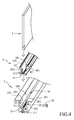
- the second embodiment of the lamp device according to the disclosure is shown to be similar to the first embodiment, and differs in that the heat dissipating seat 2 further includes a fixed bent plate 25 connected to one end of one of the lateral members 22' opposite to the base plate 21 for fixing the heat dissipating seat 2 on a support surface (not shown).
- the mounting seat 4 further includes two spaced-apart engaging members 45 extending from the base plate 41 into the receiving space 40. The engaging members 45 are respectively disposed proximate to two opposite ends of the extending plate 42.
- the assembly process of the lamp device of the second embodiment is similar to that described in the first embodiment. That is, the light emitting unit 3 is received in the receiving groove 211, and the mounting seat 4 is accommodated fixedly in the accommodation space 20 by joining the first and second engaging portions 201, 401.
- the fixed bent plate 25 is secured to a desired position of the support surface, and the light guide plate 5 is preferably directed upward. Therefore, the fixing of the light guide plate 5 does not require the fixing unit 6 as long as the light guide plate 5 is clamped by the mounting seat 4 to prevent it from falling off from the receiving space 40.
- the light guide plate 5 includes a light guide plate body 51, and two engaging notches 52 formed in the light guide plate body 51 for engagement with the engaging members 45, respectively.
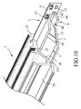
- the third embodiment of the lamp device according to the disclosure is shown to be similar to the first embodiment, and differs in the structure of the heat dissipating seat 2.
- the heat dissipating seat 2 includes the base plate 21, a support plate 26 transversely connected to an end of the base plate 21, an abutment plate 27 extending transversely from the base plate 21 opposite to the support plate 26, a folded plate 28 extending obliquely and downward from one end of the abutment plate 27 opposite to the base plate 21 and then extending along a direction parallel to the support plate 26 and away from the base plate 21, and an engaging end plate 29 connected to one end of the folding plate 28 opposite to the abutment plate 27.
- the mounting seat 4 includes the base plate 41 abutting against the light emitting unit 3, a first curved plate 46 extending arcuately from one end of the base plate 41 and abutting against the support plate 26, and a second curved plate 47 extending arcuately from the other end of the base plate 41 opposite to the first curved plate 46 and abutting against the abutment plate 27.
- the base plate 41 and the first and second curved plates 46, 47 cooperatively define the receiving space 40.
- the first and second curved plates 46, 47 are deformable toward each other.
- the mounting seat 4 can be pushed into the accommodation space 20 and retained therein after the first and second curved plates 46, 47 are restored to their original shape.
- the shape of the light guide plate 5 matches the shape of a space surrounded by the mounting seat 4 and the folded plate 28 of the heat dissipating seat 2.
- the light guide plate 5 includes a light guide main body 53 received in the receiving space 40, and a light guide portion 54 sandwiched between the light guide main body 53 and the folded plate 28.
- the light guide plate 5 can be accommodated in and secured in the space surrounded by the mounting seat 4 and the folded plate 28. Therefore, during assembly of the lamp device of the third embodiment, the fixing of the light guide plate 5 similarly does not require the fixing unit 6 either.
- the third embodiment may further include an optical component 7 having one end engaged to the engaging groove 291 of the engaging end plate 29, and another end supported by the support plate 26 such that the optical component 7 covers the light guide plate 5.
- the optical component 7 may be a brightness enhancement film.
- the light guide portion 54 is formed with a plurality of auxiliary light guide micro-structures 541, which in cooperation with the light reflective mounting seat 4, can direct the light emitted by the light sources 32 toward the desired direction for illumination. By reducing loss of light energy, the luminous efficiency of the disclosure can be enhanced.
- Each of the auxiliary light guide structure s 541 may be a microlens having a light concentrating effect or a microprism that can effectively transmit light in the light guide plate 5. As long as the auxiliary light guide structures 541 can effectively assist with guiding light, any structure thereof is acceptable, so that the structure s of the auxiliary light guide structures 541 are not limited to what is disclosed herein.
- the optical component 7 in the third embodiment may be a polarizer to polarize the emitted light, a dichroic filter to change the color of the emitted light, or other optical films having the desired effects, and is not limited to what is disclosed herein.
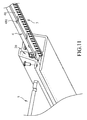
- the fourth embodiment of the lamp device according to the disclosure is shown to be similar to the first embodiment, and differs in that the mounting seat 4 and the heat dissipating seat 2 cooperatively define the receiving space 40, and the mounting seat 4 includes an extending plate 48, one side of which abuts against the light emitting unit 3.
- the extending plate 48 and a portion of the heat dissipating seat 2 cooperatively surround and form the receiving space 40 for the light guide plate 5 to extend thereinto and to mount fixedly therein.
- the extending plate 48 has a plurality of resilient protruding portions 481 which can deform and depend on a restoring force to abut resiliently against the heat dissipating seat 2.
- the resilient protruding portions 481 When the extending plate 48 and the light emitting unit 3 are inserted into the accommodation space 20, the resilient protruding portions 481 will deform toward the light emitting unit 3 due to abutment with the heat dissipating seat 2 and respectively store a resilient restoring force for resiliently abutting against the heat dissipating seat 2.
- the mounting seat 4 and the light emitting unit 3 can be stably positioned in the accommodation space 20. That is, the fourth embodiment can similarly assemble the mounting seat 4 and the light emitting unit 3 in the accommodation space 20 in a simple manner through the resilient restoring forces of the resilient protruding portions 481. Afterwards, the light guide plate 5 can be inserted into the receiving space 40.
Landscapes
- Physics & Mathematics (AREA)
- Optics & Photonics (AREA)
- General Physics & Mathematics (AREA)
- Engineering & Computer Science (AREA)
- General Engineering & Computer Science (AREA)
- Microelectronics & Electronic Packaging (AREA)
- Planar Illumination Modules (AREA)
- Arrangement Of Elements, Cooling, Sealing, Or The Like Of Lighting Devices (AREA)
- Non-Portable Lighting Devices Or Systems Thereof (AREA)
Applications Claiming Priority (1)
| Application Number | Priority Date | Filing Date | Title |
|---|---|---|---|
| TW103140223A TWI541471B (zh) | 2014-11-20 | 2014-11-20 | Lamps and lanterns |
Publications (2)
| Publication Number | Publication Date |
|---|---|
| EP3032169A2 true EP3032169A2 (fr) | 2016-06-15 |
| EP3032169A3 EP3032169A3 (fr) | 2016-10-12 |
Family
ID=52757080
Family Applications (1)
| Application Number | Title | Priority Date | Filing Date |
|---|---|---|---|
| EP15191319.1A Withdrawn EP3032169A3 (fr) | 2014-11-20 | 2015-10-23 | Dispositif de lampe |
Country Status (4)
| Country | Link |
|---|---|
| US (1) | US10067286B2 (fr) |
| EP (1) | EP3032169A3 (fr) |
| CN (1) | CN104482508A (fr) |
| TW (1) | TWI541471B (fr) |
Families Citing this family (7)
| Publication number | Priority date | Publication date | Assignee | Title |
|---|---|---|---|---|
| US20170225507A1 (en) * | 2016-02-08 | 2017-08-10 | SLIS Inc. (Really Useful Products, Inc.) | Illuminable Writing Implement |
| US10030842B1 (en) * | 2017-01-12 | 2018-07-24 | Robert A. Sonneman | Ring-shaped lights with edge effect |
| US11112556B2 (en) * | 2017-05-27 | 2021-09-07 | Nulite Lighting | Edge-lit lighting fixtures |
| CN109844402B (zh) * | 2017-09-26 | 2021-04-06 | 瑞仪光电(苏州)有限公司 | 照明装置 |
| CN111022989B (zh) * | 2019-11-25 | 2025-02-28 | 宁波晶辉光电有限公司 | 一种面板灯安装结构、面板灯及其安装方法 |
| EP4047263B1 (fr) | 2020-01-06 | 2025-02-19 | Radiant Opto-electronics (Suzhou) Co., Ltd. | Dispositif d'éclairage |
| CN115076660B (zh) * | 2022-07-04 | 2023-10-20 | 福耀玻璃工业集团股份有限公司 | 氛围灯 |
Family Cites Families (20)
| Publication number | Priority date | Publication date | Assignee | Title |
|---|---|---|---|---|
| US6095669A (en) * | 1997-08-04 | 2000-08-01 | Ilsung Moolsan Co., Ltd. | Recessed lighting fixture for sloped ceilings and baffle received therein |
| US8061865B2 (en) * | 2005-05-23 | 2011-11-22 | Philips Solid-State Lighting Solutions, Inc. | Methods and apparatus for providing lighting via a grid system of a suspended ceiling |
| US7607812B2 (en) * | 2006-05-05 | 2009-10-27 | Steven Kim | Light-emitting diode panel fixture |
| JP5414224B2 (ja) * | 2007-10-19 | 2014-02-12 | 富士フイルム株式会社 | 面状照明装置 |
| US8436974B2 (en) * | 2008-08-08 | 2013-05-07 | Sharp Kabsuhiki Kaisha | Illuminating device and liquid crystal display device provided with the same |
| US8092038B2 (en) * | 2009-03-04 | 2012-01-10 | Chunghwa Picture Tubes, Ltd. | Lamp shade |
| TWI417615B (zh) | 2009-07-07 | 2013-12-01 | Chi Lin Optoelectronics Co Ltd | 側光式背光模組 |
| WO2011070724A1 (fr) * | 2009-12-11 | 2011-06-16 | シャープ株式会社 | Appareil d'éclairage et dispositif d'affichage à cristaux liquides le comprenant |
| TW201144674A (en) | 2010-06-02 | 2011-12-16 | Radiant Opto Electronics Corp | Backlight module |
| CN201696950U (zh) * | 2010-06-22 | 2011-01-05 | 京东方科技集团股份有限公司 | 背光模组 |
| CN202188376U (zh) * | 2011-05-04 | 2012-04-11 | 苏州世鼎电子有限公司 | 具有三维电路结构与挤型罩体的背光模块 |
| KR101881846B1 (ko) * | 2011-05-12 | 2018-07-26 | 삼성디스플레이 주식회사 | 백라이트 어셈블리 및 이를 갖는 표시장치 |
| US20120294032A1 (en) * | 2011-05-18 | 2012-11-22 | Kocam International Co., Ltd. | Backlight Module with Three-Dimensional Circuit Structure |
| CN202182401U (zh) * | 2011-06-24 | 2012-04-04 | 苏永棠 | 一种车厢栅格式led灯具 |
| JP5747712B2 (ja) * | 2011-07-25 | 2015-07-15 | セイコーエプソン株式会社 | 照明装置、液晶表示装置および電子機器 |
| JP5587949B2 (ja) * | 2011-11-10 | 2014-09-10 | 京セラコネクタプロダクツ株式会社 | 半導体発光素子取付用モジュール、及び、半導体発光素子モジュール |
| JP5396498B2 (ja) * | 2012-03-02 | 2014-01-22 | 株式会社エス・ケー・ジー | 発光装置 |
| KR20140004881A (ko) * | 2012-07-03 | 2014-01-14 | 삼성디스플레이 주식회사 | 백라이트 유닛 |
| US9164227B2 (en) | 2012-07-13 | 2015-10-20 | Shenzhen China Star Optoelectronics Technology Co., Ltd | LED backlight module |
| CN103672573B (zh) * | 2012-09-11 | 2016-06-01 | 扬升照明股份有限公司 | 光源装置 |
-
2014
- 2014-11-20 TW TW103140223A patent/TWI541471B/zh active
- 2014-12-25 CN CN201410822932.4A patent/CN104482508A/zh active Pending
-
2015
- 2015-10-06 US US14/876,523 patent/US10067286B2/en active Active
- 2015-10-23 EP EP15191319.1A patent/EP3032169A3/fr not_active Withdrawn
Non-Patent Citations (1)
| Title |
|---|
| None |
Also Published As
| Publication number | Publication date |
|---|---|
| US10067286B2 (en) | 2018-09-04 |
| EP3032169A3 (fr) | 2016-10-12 |
| CN104482508A (zh) | 2015-04-01 |
| US20160147009A1 (en) | 2016-05-26 |
| TW201619551A (zh) | 2016-06-01 |
| TWI541471B (zh) | 2016-07-11 |
Similar Documents
| Publication | Publication Date | Title |
|---|---|---|
| US10067286B2 (en) | Lamp device | |
| US7044620B2 (en) | LED assembly with reverse circuit board | |
| CN105264289B (zh) | 侧光led平板式灯具 | |
| CN103249990B (zh) | 发光机构保持装置、连接件以及具有发光机构保持装置和连接件的系统 | |
| US9322531B2 (en) | LED lamp | |
| US8267565B2 (en) | LED illumination device and LED illumination module for generating uniform stripped light source | |
| CN105745487B (zh) | 拆装式led照明器具 | |
| CN103168195B (zh) | 导光部件以及具备该导光部件的发光装置 | |
| US20150219297A1 (en) | Lighting module for a motor vehicle | |
| US11262050B2 (en) | Lighting fixture | |
| TWM590655U (zh) | Led燈具模組及使用其之led燈具 | |
| US8944666B2 (en) | Lighting device | |
| CN102620155B (zh) | 光源单元及使用光源单元的装置 | |
| KR200483908Y1 (ko) | Led 평판조명등 | |
| US20190154224A1 (en) | Light module for a vehicle headlight | |
| CN107152609A (zh) | 光模块 | |
| KR101843060B1 (ko) | Led 면발광 등기구 | |
| CN112013347A (zh) | 用于机动车前照灯的照明装置 | |
| KR200483741Y1 (ko) | 에지형 면조명 장치 | |
| KR101494640B1 (ko) | 휨방지 엣지면조명장치 | |
| CN205299227U (zh) | 一种led面板灯 | |
| CN110553227A (zh) | 灯具及其光源模组 | |
| CN201141552Y (zh) | 一种镜子 | |
| TW201341717A (zh) | 燈罩 | |
| CN104566098B (zh) | 车灯装置 |
Legal Events
| Date | Code | Title | Description |
|---|---|---|---|
| PUAI | Public reference made under article 153(3) epc to a published international application that has entered the european phase |
Free format text: ORIGINAL CODE: 0009012 |
|
| AK | Designated contracting states |
Kind code of ref document: A2 Designated state(s): AL AT BE BG CH CY CZ DE DK EE ES FI FR GB GR HR HU IE IS IT LI LT LU LV MC MK MT NL NO PL PT RO RS SE SI SK SM TR |
|
| AX | Request for extension of the european patent |
Extension state: BA ME |
|
| PUAL | Search report despatched |
Free format text: ORIGINAL CODE: 0009013 |
|
| AK | Designated contracting states |
Kind code of ref document: A3 Designated state(s): AL AT BE BG CH CY CZ DE DK EE ES FI FR GB GR HR HU IE IS IT LI LT LU LV MC MK MT NL NO PL PT RO RS SE SI SK SM TR |
|
| AX | Request for extension of the european patent |
Extension state: BA ME |
|
| RIC1 | Information provided on ipc code assigned before grant |
Ipc: F21V 8/00 20060101AFI20160905BHEP |
|
| STAA | Information on the status of an ep patent application or granted ep patent |
Free format text: STATUS: THE APPLICATION IS DEEMED TO BE WITHDRAWN |
|
| 18D | Application deemed to be withdrawn |
Effective date: 20170413 |