EP3032175B1 - Ensemble paroi refroidi destiné à une chambre de combustion et procédé de conception - Google Patents
Ensemble paroi refroidi destiné à une chambre de combustion et procédé de conception Download PDFInfo
- Publication number
- EP3032175B1 EP3032175B1 EP15199825.9A EP15199825A EP3032175B1 EP 3032175 B1 EP3032175 B1 EP 3032175B1 EP 15199825 A EP15199825 A EP 15199825A EP 3032175 B1 EP3032175 B1 EP 3032175B1
- Authority
- EP
- European Patent Office
- Prior art keywords
- impingement
- effusion
- holes
- wall assembly
- pins
- Prior art date
- Legal status (The legal status is an assumption and is not a legal conclusion. Google has not performed a legal analysis and makes no representation as to the accuracy of the status listed.)
- Active
Links
Images

Classifications
-
- F—MECHANICAL ENGINEERING; LIGHTING; HEATING; WEAPONS; BLASTING
- F23—COMBUSTION APPARATUS; COMBUSTION PROCESSES
- F23M—CASINGS, LININGS, WALLS OR DOORS SPECIALLY ADAPTED FOR COMBUSTION CHAMBERS, e.g. FIREBRIDGES; DEVICES FOR DEFLECTING AIR, FLAMES OR COMBUSTION PRODUCTS IN COMBUSTION CHAMBERS; SAFETY ARRANGEMENTS SPECIALLY ADAPTED FOR COMBUSTION APPARATUS; DETAILS OF COMBUSTION CHAMBERS, NOT OTHERWISE PROVIDED FOR
- F23M5/00—Casings; Linings; Walls
- F23M5/08—Cooling thereof; Tube walls
- F23M5/085—Cooling thereof; Tube walls using air or other gas as the cooling medium
-
- F—MECHANICAL ENGINEERING; LIGHTING; HEATING; WEAPONS; BLASTING
- F23—COMBUSTION APPARATUS; COMBUSTION PROCESSES
- F23R—GENERATING COMBUSTION PRODUCTS OF HIGH PRESSURE OR HIGH VELOCITY, e.g. GAS-TURBINE COMBUSTION CHAMBERS
- F23R3/00—Continuous combustion chambers using liquid or gaseous fuel
- F23R3/002—Wall structures
-
- F—MECHANICAL ENGINEERING; LIGHTING; HEATING; WEAPONS; BLASTING
- F23—COMBUSTION APPARATUS; COMBUSTION PROCESSES
- F23R—GENERATING COMBUSTION PRODUCTS OF HIGH PRESSURE OR HIGH VELOCITY, e.g. GAS-TURBINE COMBUSTION CHAMBERS
- F23R3/00—Continuous combustion chambers using liquid or gaseous fuel
- F23R3/02—Continuous combustion chambers using liquid or gaseous fuel characterised by the air-flow or gas-flow configuration
- F23R3/04—Air inlet arrangements
- F23R3/06—Arrangement of apertures along the flame tube
-
- F—MECHANICAL ENGINEERING; LIGHTING; HEATING; WEAPONS; BLASTING
- F23—COMBUSTION APPARATUS; COMBUSTION PROCESSES
- F23M—CASINGS, LININGS, WALLS OR DOORS SPECIALLY ADAPTED FOR COMBUSTION CHAMBERS, e.g. FIREBRIDGES; DEVICES FOR DEFLECTING AIR, FLAMES OR COMBUSTION PRODUCTS IN COMBUSTION CHAMBERS; SAFETY ARRANGEMENTS SPECIALLY ADAPTED FOR COMBUSTION APPARATUS; DETAILS OF COMBUSTION CHAMBERS, NOT OTHERWISE PROVIDED FOR
- F23M2900/00—Special features of, or arrangements for combustion chambers
- F23M2900/05003—Details of manufacturing specially adapted for combustion chambers
-
- F—MECHANICAL ENGINEERING; LIGHTING; HEATING; WEAPONS; BLASTING
- F23—COMBUSTION APPARATUS; COMBUSTION PROCESSES
- F23R—GENERATING COMBUSTION PRODUCTS OF HIGH PRESSURE OR HIGH VELOCITY, e.g. GAS-TURBINE COMBUSTION CHAMBERS
- F23R2900/00—Special features of, or arrangements for continuous combustion chambers; Combustion processes therefor
- F23R2900/03041—Effusion cooled combustion chamber walls or domes
-
- F—MECHANICAL ENGINEERING; LIGHTING; HEATING; WEAPONS; BLASTING
- F23—COMBUSTION APPARATUS; COMBUSTION PROCESSES
- F23R—GENERATING COMBUSTION PRODUCTS OF HIGH PRESSURE OR HIGH VELOCITY, e.g. GAS-TURBINE COMBUSTION CHAMBERS
- F23R2900/00—Special features of, or arrangements for continuous combustion chambers; Combustion processes therefor
- F23R2900/03042—Film cooled combustion chamber walls or domes
-
- F—MECHANICAL ENGINEERING; LIGHTING; HEATING; WEAPONS; BLASTING
- F23—COMBUSTION APPARATUS; COMBUSTION PROCESSES
- F23R—GENERATING COMBUSTION PRODUCTS OF HIGH PRESSURE OR HIGH VELOCITY, e.g. GAS-TURBINE COMBUSTION CHAMBERS
- F23R2900/00—Special features of, or arrangements for continuous combustion chambers; Combustion processes therefor
- F23R2900/03044—Impingement cooled combustion chamber walls or subassemblies
-
- F—MECHANICAL ENGINEERING; LIGHTING; HEATING; WEAPONS; BLASTING
- F23—COMBUSTION APPARATUS; COMBUSTION PROCESSES
- F23R—GENERATING COMBUSTION PRODUCTS OF HIGH PRESSURE OR HIGH VELOCITY, e.g. GAS-TURBINE COMBUSTION CHAMBERS
- F23R2900/00—Special features of, or arrangements for continuous combustion chambers; Combustion processes therefor
- F23R2900/03045—Convection cooled combustion chamber walls provided with turbolators or means for creating turbulences to increase cooling
-
- Y—GENERAL TAGGING OF NEW TECHNOLOGICAL DEVELOPMENTS; GENERAL TAGGING OF CROSS-SECTIONAL TECHNOLOGIES SPANNING OVER SEVERAL SECTIONS OF THE IPC; TECHNICAL SUBJECTS COVERED BY FORMER USPC CROSS-REFERENCE ART COLLECTIONS [XRACs] AND DIGESTS
- Y02—TECHNOLOGIES OR APPLICATIONS FOR MITIGATION OR ADAPTATION AGAINST CLIMATE CHANGE
- Y02T—CLIMATE CHANGE MITIGATION TECHNOLOGIES RELATED TO TRANSPORTATION
- Y02T50/00—Aeronautics or air transport
- Y02T50/60—Efficient propulsion technologies, e.g. for aircraft
Definitions
- the present disclosure relates to a gas turbine engine and, more particularly, to cooling of a combustor wall assembly and method of design.
- Gas turbine engines such as those that power modern commercial and military aircraft, include a fan section to propel the aircraft, compressor section to pressurize a supply of air from the fan section, a combustor section to burn a hydrocarbon fuel in the presence of the pressurized air, and a turbine section to extract energy from the resultant combustion gases and generate thrust.
- the combustor section may have an annular wall assembly having inner and outer shells that support respective inner and outer heat shielding liners.
- the liners may be comprised of a plurality of floating heat shields or panels that together define an annular combustion chamber.
- An annular cooling cavity is defined between the respective shells and liners for supplying cooling air to an opposite hot side of the panels through a plurality of strategically placed effusion holes.
- Impingement holes are located in the shell for supply cooling air from an outer air plenum and into the cavity.
- the effusion holes are generally orientated to create a protective blanket, or, air film over the hot side of the panels, thereby protecting the panels from the hot combustion gases in the chamber.
- Cooling pins may be located in the cavity and project outward from the cold side of the liner to further conduct heat out of the liner.
- Prior art includes EP 2778532 A1 , EP 2233693 A1 , EP 2693122 A1 , US 2008/0264065 A1 and US 2013/0055722 A1 .
- a combustor wall assembly according to one, non-limiting, embodiment of the present disclosure is claimed in claim 1.
- the plurality of effusion holes and the plurality of impingement holes do not overlap.
- the shell is spaced from the cold face by a distance, each one of the first plurality of pins have a height within a range of thirty to seventy percent of the distance, and each one of the second plurality of pins have a height within a range of seventy-five to one-hundred percent of the distance.
- the plurality of effusion holes and the plurality of impingement holes are each arranged in an orthogonal pattern.
- the plurality of effusion holes are arranged in a plurality of effusion rows and a plurality of effusion columns
- the plurality of impingement holes are arranged in a plurality of impingement rows and a plurality of impingement columns.
- each one of the plurality of impingement rows co-extend with every other one of the plurality of effusion rows.
- each one of the plurality of impingement columns co-extend with every other one of the plurality of effusion columns.
- each one of the plurality of cooling pin arrays are arranged in an orthogonal pattern.
- each one of the plurality of cooling pin arrays are arranged in a plurality of pin rows and a plurality of pin columns.
- the plurality of pin columns is three columns and the plurality pin rows is three rows.
- the plurality of pin columns is four columns and the plurality of pin rows is four rows.
- a method of designing a cooled combustor wall assembly according to another, non-limiting, embodiment is claimed in claim 11.
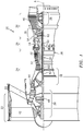
- FIG. 1 schematically illustrates a gas turbine engine 20.
- the gas turbine engine 20 is disclosed herein as a two-spool turbo fan that generally incorporates a fan section 22, a compressor section 24, a combustor section 26 and a turbine section 28.
- Alternative engines might include an augmentor section (not shown) among other systems or features.
- the fan section 22 drives air along a bypass flowpath while the compressor section 24 drives air along a core flowpath for compression and communication into the combustor section 26 then expansion through the turbine section 28.
- an intermediate spool includes an intermediate pressure compressor ("IPC") between a Low Pressure Compressor (“LPC”) and a High Pressure Compressor (“HPC”), and an Intermediate Pressure Turbine (“IPT”) between the High Pressure Turbine (“HPT”) and the Low Pressure Turbine (“LPT”).
- IPC intermediate pressure compressor
- LPC Low Pressure Compressor
- HPC High Pressure Compressor
- IPT Intermediate Pressure Turbine
- the engine 20 generally includes a low spool 30 and a high spool 32 mounted for rotation about a central, longitudinal, engine axis A relative to an engine static structure 36 or engine case via several bearing structures 38.
- the low spool 30 generally includes an inner shaft 40 that interconnects a fan 42 of the fan section 22, a LPC 44 of the compressor section 24 and a LPT 46 of the turbine section 28.
- the inner shaft 40 drives the fan 42 directly or through a geared architecture 48 to drive the fan 42 at a lower speed than the low spool 30.
- An exemplary reduction transmission is an epicyclic transmission, namely a planetary or star gear system.
- the high spool 32 includes an outer shaft 50 that interconnects a HPC 52 of the compressor section 24 and HPT 54 of the turbine section 28.
- a combustor 56 of the combustor section 26 is arranged between the HPC 52 and the HPT 54.
- the inner shaft 40 and the outer shaft 50 are concentric and rotate about the engine central longitudinal axis A that is collinear with their longitudinal axes. Core airflow is compressed by the LPC 44 then the HPC 52, mixed with the fuel and burned in the combustor 56, then expanded over the HPT 54 and the LPT 46.
- the LPT 46 and HPT 54 rotationally drive the respective low spool 30 and high spool 32 in response to the expansion.
- the gas turbine engine 20 is a high-bypass geared aircraft engine.
- the gas turbine engine 20 bypass ratio is greater than about six (6:1).
- the geared architecture 48 can include an epicyclic gear train, such as a planetary gear system or other gear system.
- the example epicyclic gear train has a gear reduction ratio of greater than about 2.3:1, and in another example is greater than about 2.5:1.
- the geared turbofan enables operation of the low spool 30 at higher speeds that can increase the operational efficiency of the LPC 44 and LPT 46 and render increased pressure in a fewer number of stages.
- a pressure ratio associated with the LPT 46 is pressure measured prior to the inlet of the LPT 46 as related to the pressure at the outlet of the LPT 46 prior to an exhaust nozzle of the gas turbine engine 20.
- the bypass ratio of the gas turbine engine 20 is greater than about ten (10:1)
- the fan diameter is significantly larger than that of the LPC 44
- the LPT 46 has a pressure ratio that is greater than about five (5:1). It should be understood; however, that the above parameters are only exemplary of one embodiment of a geared architecture engine and that the present disclosure is applicable to other gas turbine engines including direct drive turbofans.
- a significant amount of thrust is provided by the bypass flow path due to the high bypass ratio.
- the fan section 22 of the gas turbine engine 20 is designed for a particular flight condition - typically cruise at about 0.8 Mach and about 35,000 feet (10,668 meters). This flight condition, with the gas turbine engine 20 at its best fuel consumption, is also known as Thrust Specific Fuel Consumption (TSFC).
- TSFC Thrust Specific Fuel Consumption
- Fan Pressure Ratio is the pressure ratio across a blade of the fan section 22 without the use of a Fan Exit Guide Vane System.
- the low Fan Pressure Ratio according to one, non-limiting, embodiment of the example gas turbine engine 20 is less than 1.45.
- Low Corrected Fan Tip Speed is the actual fan tip speed divided by an industry standard temperature correction of (T/518.7) 0.5 in which "T" represents the ambient temperature in degrees Rankine.
- the Low Corrected Fan Tip Speed according to one non-limiting embodiment of the example gas turbine engine 20 is less than about 1,150 feet per second (351 meters per second).
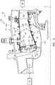
- the combustor section 26 generally includes a combustor 56 with an outer combustor wall assembly 60, an inner combustor wall assembly 62 and a diffuser case module 64 that encases assemblies 60, 62.
- the outer combustor wall assembly 60 and the inner combustor wall assembly 62 are radially spaced apart such that an annular combustion chamber 66 is defined therebetween.
- the outer combustor wall assembly 60 is spaced radially inward from an outer diffuser case 64A of the diffuser case module 64 to define an outer annular plenum 76.
- the inner combustor wall assembly 62 is spaced radially outward from an inner diffuser case 64B of the diffuser case module 64 to define an inner annular plenum 78. It should be understood that although a particular combustor is illustrated, other combustor types with various combustor liner arrangements will also benefit. It should be further understood that the disclosed cooling flow paths are but an illustrated embodiment and should not be limited.
- Each combustor wall assembly 60, 62 generally includes a respective support shell 68, 70 that supports one or more liners 72, 74 mounted thereto.
- Each of the liners 72, 74 may be formed of a plurality of floating heat shields or panels that are generally rectilinear and manufactured of, for example, a nickel based super alloy that may be coated with a ceramic, or other temperature resistant material, and are arranged to form a liner array.
- Each liner may have a plurality of forward panels 72A and a plurality of aft panels 72B that line the outer shell 68.
- a plurality of forward panels 74A and a plurality of aft panels 74B also line the inner shell 70. It should be appreciated that the liner array may alternatively include but a single panel rather than the illustrated axial forward and axial aft panels.
- the combustor 56 further includes a forward assembly 80 immediately downstream of the compressor section 24 to receive compressed airflow therefrom.
- the forward assembly 80 generally includes an annular hood 82, a bulkhead assembly 84, and a plurality of swirlers 90 (one shown).
- Each of the swirlers 90 is circumferentially aligned with one of a plurality of fuel nozzles 86 (one shown) and a respective one of a plurality of hood ports 94.
- the bulkhead assembly 84 includes a bulkhead support shell 96 secured to the combustor walls 60, 62, and a liner that may have a plurality of circumferentially distributed bulkhead heat shields or panels 98 secured to the bulkhead support shell 96 around each of a respective swirler opening 92.
- the bulkhead support shell 96 is generally annular and the plurality of circumferentially distributed bulkhead panels 98 are segmented, typically one to each fuel nozzle 86 and swirler 90.
- the annular hood 82 extends radially between, and is secured to, the forwardmost ends of the combustor wall assemblies 60, 62.
- Each one of the plurality of circumferentially distributed hood ports 94 receives a respective one of the plurality of fuel nozzles 86 and facilitates the direction of compressed air into the forward end of the combustion chamber 66 through the swirler opening 92.
- Each fuel nozzle 86 may be secured to the diffuser case module 64 and projects through one of the hood ports 94 into the respective swirler opening 92.
- the forward assembly 80 introduces core combustion air into the forward section of the combustion chamber 66 while the remainder enters the outer annular plenum 76 and the inner annular plenum 78.
- the plurality of fuel nozzles 86 and adjacent structure generate a blended fuel-air mixture that supports stable combustion in the combustion chamber 66.
- the outer and inner support shells 68, 70 may be mounted adjacent to a first row of Nozzle Guide Vanes (NGVs) 54A in the HPT 54.
- the NGVs 54A are static engine components which direct core airflow combustion gases onto the turbine blades of the first turbine rotor in the turbine section 28 to facilitate the conversion of pressure energy into kinetic energy.
- the core airflow combustion gases are also accelerated by the NGVs 54A because of their convergent shape and are typically given a "spin” or a "swirl” in the direction of turbine rotor rotation.
- the turbine rotor blades absorb this energy to drive the turbine rotor at high speed.
- the heat shield or panel 74B of liner 74 has a generally planar panel substrate 100 that may be covered by a thermal barrier coating 102 that defines a boundary of the annular combustion chamber 66.
- the liner 74 has a hot or first face 104 that may be carried by the coating 102, and an opposite cold or second face 106 carried by the substrate 100.
- An annular cooling cavity 108 of wall assembly 62 is radially defined between the cold face 106 and the shell 70 for generally receiving cooling air (see arrows 110) from the inner plenum 78 via a plurality of impingement holes 112 in the shell 70. Air flowing through the holes 110, impinge upon the cold face 106 of liner 74.
- the liner 74 has a plurality of effusion holes 114 that flow cooling air (see arrows 116) from the cooling cavity 108 and into the combustion chamber 66.
- the effusion holes 114 may be angled and/or orientated so that the cooling air 116, once in the combustion chamber 66, forms a thermally protective film or blanket of air across the liner 74.
- Each impingement hole 112 has a centerline 118 that is substantially normal to the cold face 106 of the liner 74.
- the impingement holes 112 and the effusion holes 114 may not overlap. That is, each impingement hole 112 forms a footprint 120 (i.e. a mimicking silhouette or shadow) upon the cold face 106 of the liner 74 that shares the centerline 118 and is generally spaced from the surrounding effusion holes 114.
- the impingement holes 112 (or footprints 120) may be symmetrically orientated forming a matrix (i.e. a matrix of six-by-six locations as an illustrated example) or series of rows 122 and columns 124 that may be substantially orthogonal or normal to one-another.
- the effusion holes 114 may be symmetrically orientated forming a matrix or series of rows 126 and columns 128 that may be substantially orthogonal or normal to one-another.
- the number of effusion holes 114 may substantially outnumber the number of impingement holes 112. That is, each impingement footprint 120 may generally replace what might have been a symmetrically orientated effusion hole 114. More specifically, every other row 126 and every other column 128 of the effusion holes 114 may fall along the respective rows 122 and columns 124 of the footprints 120, so that an additional effusion row 126 and effusion column 128 are located between adjacent impingement rows 122 and impingement columns 124.
- a first impingement row 122A may co-extend with a first effusion row 126A wherein the combined row has alternating impingement footprint 120 and effusion hole 114 locations (three of each illustrated).
- a second effusion row 126B is generally on its own (six effusion holes illustrated) and centered between the first impingement row 122A and a second impingement row 122B.
- the second impingement row 122B may co-extend with a third effusion row 126C wherein the combined row has alternating impingement footprint 120 and effusion hole 114 locations (three of each illustrated).
- a fourth effusion row 126D is generally on its own and centered between the second impingement row 122B and a third impingement row 122C (six effusion holes illustrated).
- the third impingement row 122C may co-extend with a fifth effusion row 126E wherein the combined row has alternating impingement footprint 120 and effusion hole 114 locations (three of each illustrated). This symmetrical pattern may repeat itself for a given region of the liner 74.
- a first impingement column 124A may co-extend with a first effusion column 128A wherein the combined column has alternating impingement footprint 120 and effusion hole 114 locations (three of each illustrated).
- a second effusion column 128B is generally on its own (six effusion holes illustrated) and centered between the first impingement column 124A and a second impingement column 124B.
- the second impingement column 124B may co-extend with a third effusion column 128C wherein the combined column has alternating impingement footprint 120 and effusion hole 114 locations (three of each illustrated).
- a fourth effusion column 128D is generally on its own and centered between the second impingement column 124B and a third impingement column 124C (six effusion holes illustrated).
- the third impingement column 124C may co-extend with a fifth effusion column 128E wherein the combined column has alternating impingement footprint 120 and effusion hole 114 locations (three of each illustrated). This symmetrical pattern may repeat itself for a given region of the liner 74.
- the liner 74 further has a plurality of cooling member arrays 130 that is generally orientated at each footprint 120 and substantially centered about the centerline 118 in the cooling cavity 108.
- Each cooling member array 130 has a radially inner plurality of members 132 (with respect to centerline 118) and an outer plurality of members 134.
- Each inner member 132 is located at least in-part within the footprint 120 (four illustrated in FIG. 4 ), and each outer member 134 is spaced outside of the footprint 120 (twelve illustrated in FIG. 4 ).
- the arrays 130 may generally be a repeating matrix of members.
- the members 132, 134 may be distributed in a matrix of rows 136 and columns 138 that are generally normal to each other. In the present example, four rows 136 and four columns 138 are illustrated for each array 130.
- Each array 130 functions to conduct heat out of the substrate 100 of the liner 74 and are cooled via the flow of cooling air 110 through the cooling cavity 108.
- the members 132, 134 may take the form of any variety of shapes including pins and/or fins. Each member 132, 134 projects outward from the cold face 106 of the liner 74 and toward the shell 70. So as not to excessively obstruct the flow of cooling air 110 through the impingement holes 112, the inner members 132 may project outward from the cold face 106 by a projecting height (see arrow 140 in FIG. 3 ) that is within a range of about thirty to seventy percent of a distance (see arrow 142) measured between the shell 70 and the cold face 106 of the liner 74.
- the outer members 134 may project outward from the cold face 106 by a projecting height (see arrow 144) that is within a range of about seventy-five to one-hundred percent of the distance 142. It is further contemplated and understood that the term "pins" may include any variety of shapes including, but not limited to, cylindrical, pyramid and rectangular shapes.
- the arrays 130 need not be composed of rows and columns, but may be any known and repeating pattern where the cooling capacity of the array can be established and repeated.
- the impingement holes 112, the effusion holes 114 and the arrays 130 need not be divided into rows and columns, but may be divided into any known and repeating pattern where the cooling capacity can be established and repeated.
- thermal expansion of the shell 70 may vary from the thermal expansion of the liner 74. This displacement difference between the shell 70 and liners may be particularly noticeable along the edges of the floating panels that may comprise the liner. Although placement of the shell impingement holes 112 relative to the liner or panel arrays 130 is generally established during cold assembly of the combustor, some compensation for thermal expansion may be desired especially near the edges of any given liner panel.
- the substrate 100 of the liner 74 may be made of a nickel-based super alloy, such as PWA 1455, or other suitable super alloys capable of withstanding elevated temperatures. Other materials and/or processes may include equiax, directionally-solidified single-crystal castings, metal powder or forged materials, composites, ceramics and hybrid combinations thereof.
- the arrays 130 may be made of the same material as the substrate 100 and cast as one unitary piece with the substrate. Alternatively, or in addition to the casting, the arrays 130 may be at least in-part machined into the casting or attached to the substrate 100 through brazing, additive manufacturing, or other means.
- the coating 102 may include a bond coat secured directly to the hot side of the substrate 100, and a thermal barrier coat that covers the bond coat and is directly exposed to the combustion chamber 66 (not shown).
- the bond coat may be associated with a thermal, corrosion prevention, and/or environmental coating system; may be made of any variety of materials including nickel, cobalt, chromium, aluminum, and others; and, may be applied to the substrate via plating, plasma spray, electron beam, vapor deposition cathodic arc, sputtering, or other means.
- the thermal barrier coat may be one or more layers and may be made of ceramic based materials and/or any combination of yttria, zirconium and others.
- a wall assembly 62' has a liner 74' that utilizes a cooling member array 130' having three rows 136' and three columns 138' of cooling members 132', 134'.
- Five inner members 132' are at least partially located within an impingement footprint 120' and four outer members 134' are located outside of the footprint 120'.
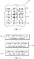
- a first step 146 may include dividing a prescribed region of a cold side 106 of a liner 74 to be cooled into a repeating pattern of impingement footprints 120.
- a repeating pattern may be a plurality of impingement rows and columns 122, 124.
- a second step 148 may include further dividing the region into a repeating pattern of effusion holes 114 orientated such that the effusion holes 114 do not overlap the impingement footprints 120.
- One such example of a repeating pattern may be a plurality of effusion rows and columns 126, 128.
- a third step 150 may include orientating a cooling member array 130 having a known cooling capacity and known size (with respect to the footprint area) to each footprint 120.
- the arrays 130, the effusion rows and columns 126, 128, and the impingement rows and columns 122, 124 may generally be located in any region of the combustor requiring cooling and that utilizes cooling holes through a shell and a liner.
- the liner 74 may be substituted for the liner or bulkhead panels 98, and the shell 70 may be substituted for the bulkhead support shell 96.
- different modifications may be made to adapt the teachings of the invention to particular situations or materials, without departing from the essential scope thereof. The invention is thus not limited to the particular examples disclosed herein, but includes all embodiments falling within the scope of the appended claims.
Landscapes
- Engineering & Computer Science (AREA)
- Chemical & Material Sciences (AREA)
- Combustion & Propulsion (AREA)
- Mechanical Engineering (AREA)
- General Engineering & Computer Science (AREA)
- Turbine Rotor Nozzle Sealing (AREA)
Claims (11)
- Ensemble paroi de chambre de combustion comprenant :un revêtement (74) comportant une face chaude (104) définissant une chambre de combustion (66), une face froide opposée (106) et une pluralité de trous d'effusion (114) ;une coque (70) espacée vers l'extérieur de la face froide (106), la coque (70) comportant une pluralité de trous d'impact (112), chaque trou d'impact (112) ayant une ligne centrale (118) orientée sensiblement perpendiculairement à la face froide (106) ; etune pluralité de réseaux de broches de refroidissement (130), chaque réseau de broches de refroidissement (130) comportant une première pluralité de broches (132) faisant saillie vers l'extérieur depuis la face froide (106), dans lequel chaque réseau de broches (130) est espacé entre des trous d'effusion (114) adjacents de la pluralité de trous d'effusion (114) et agencé autour de la ligne centrale (118) du trou d'impact (112) respectif,dans lequel chacun de la pluralité de trous d'impact (112) comporte une empreinte (120) coulée sur la face froide (106) autour de la ligne centrale (118) respective et espacée de trous d'effusion (114) adjacents de la pluralité de trous d'effusion (114), caractérisé en ce que :chaque broche (132) de la première pluralité de broches (132) est située au moins en partie à l'intérieur de l'empreinte (120) ;chacun de la pluralité de réseaux de broches de refroidissement (130) comporte une seconde pluralité de broches (134) disposée à l'extérieur de l'empreinte (120) ; etla première pluralité de broches (132) sont plus courtes que les broches de la seconde pluralité de broches (134).
- Ensemble paroi de chambre de combustion selon la revendication 1, dans lequel la pluralité de trous d'effusion (114) et la pluralité de trous d'impact (112) ne se chevauchent pas.
- Ensemble paroi de chambre de combustion selon la revendication 1 ou 2, dans lequel la coque (70) est espacée de la face froide (106) d'une distance, chacune de la première pluralité de broches (132) a une hauteur (140) dans une plage de trente à soixante-dix pour cent de la distance (142), et chacune de la seconde pluralité de broches (134) a une hauteur (144) dans une plage de soixante-quinze à cent pour cent de la distance (142).
- Ensemble paroi de chambre de combustion selon la revendication 1, 2 ou 3, dans lequel la pluralité de trous d'effusion (114) et la pluralité de trous d'impact (112) sont chacune agencées selon un motif orthogonal.
- Ensemble paroi de chambre de combustion selon la revendication 4, dans lequel la pluralité de trous d'effusion (114) sont agencés dans une pluralité de rangées d'effusion (126A-E) et une pluralité de colonnes d'effusion (128A-E), et la pluralité de trous d'impact (112) sont agencés dans une pluralité de rangées d'impact (122A-C) et une pluralité de colonnes d'impact (124A-C).
- Ensemble paroi de chambre de combustion selon la revendication 5, dans lequel chacune de la pluralité de rangées d'impact (122A-C) s'étend conjointement avec chaque autre rangée de la pluralité de rangées d'effusion (126A-E).
- Ensemble paroi de chambre de combustion selon la revendication 5 ou 6, dans lequel chacune de la pluralité de colonnes d'impact (124A-C) s'étend conjointement avec chaque autre colonne de la pluralité de colonnes d'effusion (128A-E).
- Ensemble paroi de chambre de combustion selon une quelconque revendication précédente, dans lequel chacun de la pluralité de réseaux de broches de refroidissement (130) est agencé selon un motif orthogonal.
- Ensemble paroi de chambre de combustion selon la revendication 8, dans lequel chacun de la pluralité de réseaux de broches de refroidissement (130) est agencé dans une pluralité de rangées de broches (136) et une pluralité de colonnes de broches (138).
- Ensemble paroi de chambre de combustion selon la revendication 9, dans lequel :la pluralité de colonnes de broches (138) est constituée de trois colonnes et la pluralité de rangées de broches (136) est constituée de trois rangées ; oula pluralité de colonnes de broches (138) est constituée de quatre colonnes et la pluralité de rangées de broches (136) est constituée de quatre rangées.
- Procédé de conception d'un ensemble paroi de chambre de combustion refroidi comprenant les étapes :de séparation d'une région d'un côté froid (106) d'un revêtement (74) à refroidir en un motif répétitif d'empreintes d'impact (120) ;de séparation de la région en un motif répétitif de trous d'effusion (114) agencé de sorte que les trous d'effusion (114) ne chevauchent pas les empreintes d'impact (120) ; etd'agencement d'au moins un réseau d'éléments de refroidissement (130) ayant une capacité de refroidissement connue pour chaque empreinte (120) respective ; dans lequel :l'au moins un réseau d'éléments de refroidissement (130) comporte une première pluralité de broches (132) qui font saillie vers l'extérieur depuis la face froide (106), dans lequel chaque réseau de broches (130) est espacé entre des trous d'effusion (114) adjacents des trous d'effusion (114) et agencé autour d'une ligne centrale (118) du trou d'impact (112) respectif ; etchacun de la pluralité de trous d'impact (112) comporte une empreinte (120) coulée sur le côté froid (106) autour de la ligne centrale (118) respective et espacée de trous d'effusion (114) adjacents de la pluralité de trous d'effusion (114) ; caractérisé en ce que :chaque broche (132) de la première pluralité de broches (132) est située au moins en partie à l'intérieur de l'empreinte (120) ;chacun de la pluralité de réseaux de broches de refroidissement (130) comporte une seconde pluralité de broches (134) disposée à l'extérieur de l'empreinte (120) ; etla première pluralité de broches (132) sont plus courtes que les broches de la seconde pluralité de broches (134).
Applications Claiming Priority (1)
| Application Number | Priority Date | Filing Date | Title |
|---|---|---|---|
| US201462091189P | 2014-12-12 | 2014-12-12 |
Publications (2)
| Publication Number | Publication Date |
|---|---|
| EP3032175A1 EP3032175A1 (fr) | 2016-06-15 |
| EP3032175B1 true EP3032175B1 (fr) | 2020-02-05 |
Family
ID=54849838
Family Applications (1)
| Application Number | Title | Priority Date | Filing Date |
|---|---|---|---|
| EP15199825.9A Active EP3032175B1 (fr) | 2014-12-12 | 2015-12-14 | Ensemble paroi refroidi destiné à une chambre de combustion et procédé de conception |
Country Status (2)
| Country | Link |
|---|---|
| US (1) | US10746403B2 (fr) |
| EP (1) | EP3032175B1 (fr) |
Families Citing this family (12)
| Publication number | Priority date | Publication date | Assignee | Title |
|---|---|---|---|---|
| US10598382B2 (en) * | 2014-11-07 | 2020-03-24 | United Technologies Corporation | Impingement film-cooled floatwall with backside feature |
| EP3205937B1 (fr) * | 2016-02-09 | 2021-03-31 | Ansaldo Energia IP UK Limited | Agencement de paroi refroidie par impact |
| US10684014B2 (en) * | 2016-08-04 | 2020-06-16 | Raytheon Technologies Corporation | Combustor panel for gas turbine engine |
| CN106247402B (zh) * | 2016-08-12 | 2019-04-23 | 中国航空工业集团公司沈阳发动机设计研究所 | 一种火焰筒 |
| US20180283690A1 (en) * | 2017-03-29 | 2018-10-04 | United Technologies Corporation | Combustor panel heat transfer pins with varying geometric specifications |
| US10816202B2 (en) * | 2017-11-28 | 2020-10-27 | General Electric Company | Combustor liner for a gas turbine engine and an associated method thereof |
| US12560325B2 (en) * | 2017-12-19 | 2026-02-24 | Rtx Corporation | Apparatus and method for mitigating particulate accumulation on a component of a gas turbine engine |
| US10823414B2 (en) * | 2018-03-19 | 2020-11-03 | Raytheon Technologies Corporation | Hooded entrance to effusion holes |
| US11339718B2 (en) * | 2018-11-09 | 2022-05-24 | Raytheon Technologies Corporation | Minicore cooling passage network having trip strips |
| US11125434B2 (en) * | 2018-12-10 | 2021-09-21 | Raytheon Technologies Corporation | Preferential flow distribution for gas turbine engine component |
| US11226099B2 (en) * | 2019-10-11 | 2022-01-18 | Rolls-Royce Corporation | Combustor liner for a gas turbine engine with ceramic matrix composite components |
| CN112178691B (zh) * | 2020-10-27 | 2022-05-13 | 西北工业大学 | 一种带气膜孔双曲扰流柱的双层壁冷却结构 |
Citations (2)
| Publication number | Priority date | Publication date | Assignee | Title |
|---|---|---|---|---|
| US20130055722A1 (en) * | 2011-09-06 | 2013-03-07 | Jeffrey Verhiel | Pin fin arrangement for heat shield of gas turbine engine |
| EP3018416A1 (fr) * | 2014-11-07 | 2016-05-11 | United Technologies Corporation | Paroi flottante à empiètement refroidie par film avec caractéristique de côté arrière |
Family Cites Families (23)
| Publication number | Priority date | Publication date | Assignee | Title |
|---|---|---|---|---|
| JPH0660740B2 (ja) * | 1985-04-05 | 1994-08-10 | 工業技術院長 | ガスタービンの燃焼器 |
| DE4430302A1 (de) * | 1994-08-26 | 1996-02-29 | Abb Management Ag | Prallgekühltes Wandteil |
| US6964170B2 (en) * | 2003-04-28 | 2005-11-15 | Pratt & Whitney Canada Corp. | Noise reducing combustor |
| US7699583B2 (en) | 2006-07-21 | 2010-04-20 | United Technologies Corporation | Serpentine microcircuit vortex turbulatons for blade cooling |
| DE102007018061A1 (de) | 2007-04-17 | 2008-10-23 | Rolls-Royce Deutschland Ltd & Co Kg | Gasturbinenbrennkammerwand |
| JP2009162119A (ja) | 2008-01-08 | 2009-07-23 | Ihi Corp | タービン翼の冷却構造 |
| CH700319A1 (de) * | 2009-01-30 | 2010-07-30 | Alstom Technology Ltd | Gekühltes bauelement für eine gasturbine. |
| US9334741B2 (en) * | 2010-04-22 | 2016-05-10 | Siemens Energy, Inc. | Discreetly defined porous wall structure for transpirational cooling |
| US8201412B2 (en) * | 2010-09-13 | 2012-06-19 | General Electric Company | Apparatus and method for cooling a combustor |
| JP5696566B2 (ja) | 2011-03-31 | 2015-04-08 | 株式会社Ihi | ガスタービンエンジン用燃焼器及びガスタービンエンジン |
| US8978385B2 (en) | 2011-07-29 | 2015-03-17 | United Technologies Corporation | Distributed cooling for gas turbine engine combustor |
| US9057523B2 (en) | 2011-07-29 | 2015-06-16 | United Technologies Corporation | Microcircuit cooling for gas turbine engine combustor |
| JP5821550B2 (ja) * | 2011-11-10 | 2015-11-24 | 株式会社Ihi | 燃焼器ライナ |
| JP5927893B2 (ja) * | 2011-12-15 | 2016-06-01 | 株式会社Ihi | インピンジ冷却機構、タービン翼及び燃焼器 |
| US20130180252A1 (en) * | 2012-01-18 | 2013-07-18 | General Electric Company | Combustor assembly with impingement sleeve holes and turbulators |
| US9243801B2 (en) | 2012-06-07 | 2016-01-26 | United Technologies Corporation | Combustor liner with improved film cooling |
| US9239165B2 (en) | 2012-06-07 | 2016-01-19 | United Technologies Corporation | Combustor liner with convergent cooling channel |
| US9217568B2 (en) | 2012-06-07 | 2015-12-22 | United Technologies Corporation | Combustor liner with decreased liner cooling |
| US9194585B2 (en) | 2012-10-04 | 2015-11-24 | United Technologies Corporation | Cooling for combustor liners with accelerating channels |
| EP2946092B1 (fr) | 2013-01-17 | 2019-04-17 | United Technologies Corporation | Ensemble revêtement pour chambre de combustion de turbine à gaz équipé d'un profil hyperbolique convergent |
| US9879861B2 (en) * | 2013-03-15 | 2018-01-30 | Rolls-Royce Corporation | Gas turbine engine with improved combustion liner |
| US10443848B2 (en) | 2014-04-02 | 2019-10-15 | United Technologies Corporation | Grommet assembly and method of design |
| US9909761B2 (en) | 2014-04-09 | 2018-03-06 | United Technologies Corporation | Combustor wall assembly for a turbine engine |
-
2015
- 2015-11-12 US US14/939,619 patent/US10746403B2/en active Active
- 2015-12-14 EP EP15199825.9A patent/EP3032175B1/fr active Active
Patent Citations (2)
| Publication number | Priority date | Publication date | Assignee | Title |
|---|---|---|---|---|
| US20130055722A1 (en) * | 2011-09-06 | 2013-03-07 | Jeffrey Verhiel | Pin fin arrangement for heat shield of gas turbine engine |
| EP3018416A1 (fr) * | 2014-11-07 | 2016-05-11 | United Technologies Corporation | Paroi flottante à empiètement refroidie par film avec caractéristique de côté arrière |
Also Published As
| Publication number | Publication date |
|---|---|
| US10746403B2 (en) | 2020-08-18 |
| US20160169512A1 (en) | 2016-06-16 |
| EP3032175A1 (fr) | 2016-06-15 |
Similar Documents
| Publication | Publication Date | Title |
|---|---|---|
| EP3032175B1 (fr) | Ensemble paroi refroidi destiné à une chambre de combustion et procédé de conception | |
| EP3077728B1 (fr) | Chambre de combustion de moteur à turbine à gaz ayant des passages d'effusion avec orientation de co-tourbillonnement, et procédé | |
| EP3008387B1 (fr) | Augmentation du refroidissement d'une surface de panneau conducteur pour chambre de combustion de moteur à turbine à gaz | |
| EP3438537B1 (fr) | Panneau de chemise de chambre de combustion comportant de multiples nervures de transfert de chaleur pour une chambre de combustion d'un moteur à turbine à gaz | |
| EP2995863B1 (fr) | Brûleur à paroi unique pour un moteur à turbine à gaz et procédé de fabrication | |
| EP3315865B1 (fr) | Panneau de chemise de chambre de combustion comportant de multiples amplificateurs de transfert de chaleur pour une chambre de combustion d'un moteur à turbine à gaz | |
| EP3086041B1 (fr) | Écran thermique de brûleur à fabrication additive | |
| EP2995864B1 (fr) | Circuit de refroidissement par film pour une chemise de chambre de combustion et procede de fabrication du circuit de refroidissement | |
| EP3366997B1 (fr) | Caractéristiques d'amélioration de refroidissement de rail d'extrémité de panneau de chemise de chambre de combustion pour une chambre de combustion de turbine à gaz | |
| EP3361158B1 (fr) | Chambre de combustion pour une turbine à gaz | |
| EP3321586B1 (fr) | Chambre de combustion de moteur à turbine à gaz avec un panneau de chambre de combustion revêtu et procédé de son manufacture | |
| EP3084303B1 (fr) | Réseau de dépressions mécaniques thermiques pour un ensemble paroi de chambre de combustion | |
| EP3321585B1 (fr) | Panneau de chemise de chambre de combustion non plane pour chambre de combustion de turbine à gaz | |
| EP4328488B1 (fr) | Chambre de combustion pour turbine à gaz avec panneau de revêtement avec porte arrondie | |
| EP3318803B1 (fr) | Arrangement de barres de renforcement pour chambre de combustion de moteur de turbine à gaz | |
| EP3315862B1 (fr) | Panneau de revêtement moulé de chambre de combustion comportant un bord a rayon pour chambre de combustion de turbine à gaz | |
| EP3321588B1 (fr) | Chambre de combustion pour un moteur de turbine à gaz | |
| EP3315864A2 (fr) | Panneau de revêtement de combustion coulé à illet de passage de dilution arrondi pour chambre de combustion de moteur de turbine à gaz |
Legal Events
| Date | Code | Title | Description |
|---|---|---|---|
| PUAI | Public reference made under article 153(3) epc to a published international application that has entered the european phase |
Free format text: ORIGINAL CODE: 0009012 |
|
| AK | Designated contracting states |
Kind code of ref document: A1 Designated state(s): AL AT BE BG CH CY CZ DE DK EE ES FI FR GB GR HR HU IE IS IT LI LT LU LV MC MK MT NL NO PL PT RO RS SE SI SK SM TR |
|
| AX | Request for extension of the european patent |
Extension state: BA ME |
|
| RAP1 | Party data changed (applicant data changed or rights of an application transferred) |
Owner name: UNITED TECHNOLOGIES CORPORATION |
|
| STAA | Information on the status of an ep patent application or granted ep patent |
Free format text: STATUS: REQUEST FOR EXAMINATION WAS MADE |
|
| 17P | Request for examination filed |
Effective date: 20161214 |
|
| RBV | Designated contracting states (corrected) |
Designated state(s): AL AT BE BG CH CY CZ DE DK EE ES FI FR GB GR HR HU IE IS IT LI LT LU LV MC MK MT NL NO PL PT RO RS SE SI SK SM TR |
|
| STAA | Information on the status of an ep patent application or granted ep patent |
Free format text: STATUS: EXAMINATION IS IN PROGRESS |
|
| 17Q | First examination report despatched |
Effective date: 20180801 |
|
| GRAP | Despatch of communication of intention to grant a patent |
Free format text: ORIGINAL CODE: EPIDOSNIGR1 |
|
| STAA | Information on the status of an ep patent application or granted ep patent |
Free format text: STATUS: GRANT OF PATENT IS INTENDED |
|
| INTG | Intention to grant announced |
Effective date: 20190723 |
|
| GRAS | Grant fee paid |
Free format text: ORIGINAL CODE: EPIDOSNIGR3 |
|
| GRAA | (expected) grant |
Free format text: ORIGINAL CODE: 0009210 |
|
| STAA | Information on the status of an ep patent application or granted ep patent |
Free format text: STATUS: THE PATENT HAS BEEN GRANTED |
|
| AK | Designated contracting states |
Kind code of ref document: B1 Designated state(s): AL AT BE BG CH CY CZ DE DK EE ES FI FR GB GR HR HU IE IS IT LI LT LU LV MC MK MT NL NO PL PT RO RS SE SI SK SM TR |
|
| REG | Reference to a national code |
Ref country code: GB Ref legal event code: FG4D |
|
| REG | Reference to a national code |
Ref country code: AT Ref legal event code: REF Ref document number: 1230183 Country of ref document: AT Kind code of ref document: T Effective date: 20200215 |
|
| REG | Reference to a national code |
Ref country code: DE Ref legal event code: R096 Ref document number: 602015046376 Country of ref document: DE |
|
| REG | Reference to a national code |
Ref country code: IE Ref legal event code: FG4D |
|
| REG | Reference to a national code |
Ref country code: CH Ref legal event code: EP |
|
| REG | Reference to a national code |
Ref country code: NL Ref legal event code: MP Effective date: 20200205 |
|
| PG25 | Lapsed in a contracting state [announced via postgrant information from national office to epo] |
Ref country code: PT Free format text: LAPSE BECAUSE OF FAILURE TO SUBMIT A TRANSLATION OF THE DESCRIPTION OR TO PAY THE FEE WITHIN THE PRESCRIBED TIME-LIMIT Effective date: 20200628 Ref country code: NO Free format text: LAPSE BECAUSE OF FAILURE TO SUBMIT A TRANSLATION OF THE DESCRIPTION OR TO PAY THE FEE WITHIN THE PRESCRIBED TIME-LIMIT Effective date: 20200505 Ref country code: FI Free format text: LAPSE BECAUSE OF FAILURE TO SUBMIT A TRANSLATION OF THE DESCRIPTION OR TO PAY THE FEE WITHIN THE PRESCRIBED TIME-LIMIT Effective date: 20200205 Ref country code: RS Free format text: LAPSE BECAUSE OF FAILURE TO SUBMIT A TRANSLATION OF THE DESCRIPTION OR TO PAY THE FEE WITHIN THE PRESCRIBED TIME-LIMIT Effective date: 20200205 |
|
| REG | Reference to a national code |
Ref country code: LT Ref legal event code: MG4D |
|
| PG25 | Lapsed in a contracting state [announced via postgrant information from national office to epo] |
Ref country code: GR Free format text: LAPSE BECAUSE OF FAILURE TO SUBMIT A TRANSLATION OF THE DESCRIPTION OR TO PAY THE FEE WITHIN THE PRESCRIBED TIME-LIMIT Effective date: 20200506 Ref country code: HR Free format text: LAPSE BECAUSE OF FAILURE TO SUBMIT A TRANSLATION OF THE DESCRIPTION OR TO PAY THE FEE WITHIN THE PRESCRIBED TIME-LIMIT Effective date: 20200205 Ref country code: LV Free format text: LAPSE BECAUSE OF FAILURE TO SUBMIT A TRANSLATION OF THE DESCRIPTION OR TO PAY THE FEE WITHIN THE PRESCRIBED TIME-LIMIT Effective date: 20200205 Ref country code: IS Free format text: LAPSE BECAUSE OF FAILURE TO SUBMIT A TRANSLATION OF THE DESCRIPTION OR TO PAY THE FEE WITHIN THE PRESCRIBED TIME-LIMIT Effective date: 20200605 Ref country code: SE Free format text: LAPSE BECAUSE OF FAILURE TO SUBMIT A TRANSLATION OF THE DESCRIPTION OR TO PAY THE FEE WITHIN THE PRESCRIBED TIME-LIMIT Effective date: 20200205 Ref country code: BG Free format text: LAPSE BECAUSE OF FAILURE TO SUBMIT A TRANSLATION OF THE DESCRIPTION OR TO PAY THE FEE WITHIN THE PRESCRIBED TIME-LIMIT Effective date: 20200505 |
|
| PG25 | Lapsed in a contracting state [announced via postgrant information from national office to epo] |
Ref country code: NL Free format text: LAPSE BECAUSE OF FAILURE TO SUBMIT A TRANSLATION OF THE DESCRIPTION OR TO PAY THE FEE WITHIN THE PRESCRIBED TIME-LIMIT Effective date: 20200205 |
|
| PG25 | Lapsed in a contracting state [announced via postgrant information from national office to epo] |
Ref country code: ES Free format text: LAPSE BECAUSE OF FAILURE TO SUBMIT A TRANSLATION OF THE DESCRIPTION OR TO PAY THE FEE WITHIN THE PRESCRIBED TIME-LIMIT Effective date: 20200205 Ref country code: CZ Free format text: LAPSE BECAUSE OF FAILURE TO SUBMIT A TRANSLATION OF THE DESCRIPTION OR TO PAY THE FEE WITHIN THE PRESCRIBED TIME-LIMIT Effective date: 20200205 Ref country code: RO Free format text: LAPSE BECAUSE OF FAILURE TO SUBMIT A TRANSLATION OF THE DESCRIPTION OR TO PAY THE FEE WITHIN THE PRESCRIBED TIME-LIMIT Effective date: 20200205 Ref country code: DK Free format text: LAPSE BECAUSE OF FAILURE TO SUBMIT A TRANSLATION OF THE DESCRIPTION OR TO PAY THE FEE WITHIN THE PRESCRIBED TIME-LIMIT Effective date: 20200205 Ref country code: SK Free format text: LAPSE BECAUSE OF FAILURE TO SUBMIT A TRANSLATION OF THE DESCRIPTION OR TO PAY THE FEE WITHIN THE PRESCRIBED TIME-LIMIT Effective date: 20200205 Ref country code: SM Free format text: LAPSE BECAUSE OF FAILURE TO SUBMIT A TRANSLATION OF THE DESCRIPTION OR TO PAY THE FEE WITHIN THE PRESCRIBED TIME-LIMIT Effective date: 20200205 Ref country code: LT Free format text: LAPSE BECAUSE OF FAILURE TO SUBMIT A TRANSLATION OF THE DESCRIPTION OR TO PAY THE FEE WITHIN THE PRESCRIBED TIME-LIMIT Effective date: 20200205 Ref country code: EE Free format text: LAPSE BECAUSE OF FAILURE TO SUBMIT A TRANSLATION OF THE DESCRIPTION OR TO PAY THE FEE WITHIN THE PRESCRIBED TIME-LIMIT Effective date: 20200205 |
|
| REG | Reference to a national code |
Ref country code: DE Ref legal event code: R097 Ref document number: 602015046376 Country of ref document: DE |
|
| REG | Reference to a national code |
Ref country code: AT Ref legal event code: MK05 Ref document number: 1230183 Country of ref document: AT Kind code of ref document: T Effective date: 20200205 |
|
| PLBE | No opposition filed within time limit |
Free format text: ORIGINAL CODE: 0009261 |
|
| STAA | Information on the status of an ep patent application or granted ep patent |
Free format text: STATUS: NO OPPOSITION FILED WITHIN TIME LIMIT |
|
| 26N | No opposition filed |
Effective date: 20201106 |
|
| PG25 | Lapsed in a contracting state [announced via postgrant information from national office to epo] |
Ref country code: IT Free format text: LAPSE BECAUSE OF FAILURE TO SUBMIT A TRANSLATION OF THE DESCRIPTION OR TO PAY THE FEE WITHIN THE PRESCRIBED TIME-LIMIT Effective date: 20200205 Ref country code: AT Free format text: LAPSE BECAUSE OF FAILURE TO SUBMIT A TRANSLATION OF THE DESCRIPTION OR TO PAY THE FEE WITHIN THE PRESCRIBED TIME-LIMIT Effective date: 20200205 |
|
| PG25 | Lapsed in a contracting state [announced via postgrant information from national office to epo] |
Ref country code: PL Free format text: LAPSE BECAUSE OF FAILURE TO SUBMIT A TRANSLATION OF THE DESCRIPTION OR TO PAY THE FEE WITHIN THE PRESCRIBED TIME-LIMIT Effective date: 20200205 Ref country code: SI Free format text: LAPSE BECAUSE OF FAILURE TO SUBMIT A TRANSLATION OF THE DESCRIPTION OR TO PAY THE FEE WITHIN THE PRESCRIBED TIME-LIMIT Effective date: 20200205 |
|
| REG | Reference to a national code |
Ref country code: CH Ref legal event code: PL |
|
| PG25 | Lapsed in a contracting state [announced via postgrant information from national office to epo] |
Ref country code: MC Free format text: LAPSE BECAUSE OF FAILURE TO SUBMIT A TRANSLATION OF THE DESCRIPTION OR TO PAY THE FEE WITHIN THE PRESCRIBED TIME-LIMIT Effective date: 20200205 |
|
| REG | Reference to a national code |
Ref country code: BE Ref legal event code: MM Effective date: 20201231 |
|
| PG25 | Lapsed in a contracting state [announced via postgrant information from national office to epo] |
Ref country code: LU Free format text: LAPSE BECAUSE OF NON-PAYMENT OF DUE FEES Effective date: 20201214 Ref country code: IE Free format text: LAPSE BECAUSE OF NON-PAYMENT OF DUE FEES Effective date: 20201214 |
|
| PG25 | Lapsed in a contracting state [announced via postgrant information from national office to epo] |
Ref country code: LI Free format text: LAPSE BECAUSE OF NON-PAYMENT OF DUE FEES Effective date: 20201231 Ref country code: CH Free format text: LAPSE BECAUSE OF NON-PAYMENT OF DUE FEES Effective date: 20201231 |
|
| PG25 | Lapsed in a contracting state [announced via postgrant information from national office to epo] |
Ref country code: TR Free format text: LAPSE BECAUSE OF FAILURE TO SUBMIT A TRANSLATION OF THE DESCRIPTION OR TO PAY THE FEE WITHIN THE PRESCRIBED TIME-LIMIT Effective date: 20200205 Ref country code: MT Free format text: LAPSE BECAUSE OF FAILURE TO SUBMIT A TRANSLATION OF THE DESCRIPTION OR TO PAY THE FEE WITHIN THE PRESCRIBED TIME-LIMIT Effective date: 20200205 Ref country code: CY Free format text: LAPSE BECAUSE OF FAILURE TO SUBMIT A TRANSLATION OF THE DESCRIPTION OR TO PAY THE FEE WITHIN THE PRESCRIBED TIME-LIMIT Effective date: 20200205 |
|
| PG25 | Lapsed in a contracting state [announced via postgrant information from national office to epo] |
Ref country code: MK Free format text: LAPSE BECAUSE OF FAILURE TO SUBMIT A TRANSLATION OF THE DESCRIPTION OR TO PAY THE FEE WITHIN THE PRESCRIBED TIME-LIMIT Effective date: 20200205 Ref country code: AL Free format text: LAPSE BECAUSE OF FAILURE TO SUBMIT A TRANSLATION OF THE DESCRIPTION OR TO PAY THE FEE WITHIN THE PRESCRIBED TIME-LIMIT Effective date: 20200205 |
|
| PG25 | Lapsed in a contracting state [announced via postgrant information from national office to epo] |
Ref country code: BE Free format text: LAPSE BECAUSE OF NON-PAYMENT OF DUE FEES Effective date: 20201231 |
|
| REG | Reference to a national code |
Ref country code: DE Ref legal event code: R081 Ref document number: 602015046376 Country of ref document: DE Owner name: RAYTHEON TECHNOLOGIES CORPORATION (N.D.GES.D.S, US Free format text: FORMER OWNER: UNITED TECHNOLOGIES CORPORATION, FARMINGTON, CONN., US Ref country code: DE Ref legal event code: R081 Ref document number: 602015046376 Country of ref document: DE Owner name: RTX CORPORATION (N.D.GES.D. STAATES DELAWARE),, US Free format text: FORMER OWNER: UNITED TECHNOLOGIES CORPORATION, FARMINGTON, CONN., US |
|
| P01 | Opt-out of the competence of the unified patent court (upc) registered |
Effective date: 20230520 |
|
| REG | Reference to a national code |
Ref country code: DE Ref legal event code: R081 Ref document number: 602015046376 Country of ref document: DE Owner name: RTX CORPORATION (N.D.GES.D. STAATES DELAWARE),, US Free format text: FORMER OWNER: RAYTHEON TECHNOLOGIES CORPORATION (N.D.GES.D.STAATES DELAWARE), ARLINGTON, VA, US |
|
| PGFP | Annual fee paid to national office [announced via postgrant information from national office to epo] |
Ref country code: DE Payment date: 20251126 Year of fee payment: 11 |
|
| PGFP | Annual fee paid to national office [announced via postgrant information from national office to epo] |
Ref country code: GB Payment date: 20251120 Year of fee payment: 11 |
|
| PGFP | Annual fee paid to national office [announced via postgrant information from national office to epo] |
Ref country code: FR Payment date: 20251119 Year of fee payment: 11 |