EP3032677B1 - Réseau électrique à courant continu - Google Patents
Réseau électrique à courant continu Download PDFInfo
- Publication number
- EP3032677B1 EP3032677B1 EP14275256.7A EP14275256A EP3032677B1 EP 3032677 B1 EP3032677 B1 EP 3032677B1 EP 14275256 A EP14275256 A EP 14275256A EP 3032677 B1 EP3032677 B1 EP 3032677B1
- Authority
- EP
- European Patent Office
- Prior art keywords
- transmission path
- current
- current flow
- transmission
- active power
- Prior art date
- Legal status (The legal status is an assumption and is not a legal conclusion. Google has not performed a legal analysis and makes no representation as to the accuracy of the status listed.)
- Active
Links
Images



Classifications
-
- H—ELECTRICITY
- H02—GENERATION; CONVERSION OR DISTRIBUTION OF ELECTRIC POWER
- H02H—EMERGENCY PROTECTIVE CIRCUIT ARRANGEMENTS
- H02H7/00—Emergency protective circuit arrangements specially adapted for specific types of electric machines or apparatus or for sectionalised protection of cable or line systems, and effecting automatic switching in the event of an undesired change from normal working conditions
- H02H7/26—Sectionalised protection of cable or line systems, e.g. for disconnecting a section on which a short-circuit, earth fault, or arc discharge has occured
- H02H7/268—Sectionalised protection of cable or line systems, e.g. for disconnecting a section on which a short-circuit, earth fault, or arc discharge has occured for DC systems
-
- H—ELECTRICITY
- H02—GENERATION; CONVERSION OR DISTRIBUTION OF ELECTRIC POWER
- H02H—EMERGENCY PROTECTIVE CIRCUIT ARRANGEMENTS
- H02H3/00—Emergency protective circuit arrangements for automatic disconnection directly responsive to an undesired change from normal electric working condition with or without subsequent reconnection ; integrated protection
- H02H3/02—Details
- H02H3/021—Details concerning the disconnection itself, e.g. at a particular instant, particularly at zero value of current, disconnection in a predetermined order
-
- H—ELECTRICITY
- H02—GENERATION; CONVERSION OR DISTRIBUTION OF ELECTRIC POWER
- H02H—EMERGENCY PROTECTIVE CIRCUIT ARRANGEMENTS
- H02H7/00—Emergency protective circuit arrangements specially adapted for specific types of electric machines or apparatus or for sectionalised protection of cable or line systems, and effecting automatic switching in the event of an undesired change from normal working conditions
- H02H7/26—Sectionalised protection of cable or line systems, e.g. for disconnecting a section on which a short-circuit, earth fault, or arc discharge has occured
- H02H7/28—Sectionalised protection of cable or line systems, e.g. for disconnecting a section on which a short-circuit, earth fault, or arc discharge has occured for meshed systems
-
- H—ELECTRICITY
- H02—GENERATION; CONVERSION OR DISTRIBUTION OF ELECTRIC POWER
- H02H—EMERGENCY PROTECTIVE CIRCUIT ARRANGEMENTS
- H02H3/00—Emergency protective circuit arrangements for automatic disconnection directly responsive to an undesired change from normal electric working condition with or without subsequent reconnection ; integrated protection
- H02H3/02—Details
- H02H3/025—Disconnection after limiting, e.g. when limiting is not sufficient or for facilitating disconnection
Definitions
- This invention relates to a DC electrical network, and a method of fault clearance for a DC electrical network.
- a DC electrical network may include a power source, such as a battery, that is connected to a load via one or more current-carrying conductors, or multiple power sources that are connected to multiple loads using a network of current-carrying conductors.
- a power source such as a battery
- An example of a DC electrical network is a DC power grid that requires multi-terminal interconnection of HVDC converters, whereby power can be exchanged on the DC side using two or more HVDC converters electrically connected together.
- Each HVDC converter acts as either a source or sink to maintain the overall input-to-output power balance of the DC power grid whilst exchanging the power as required.
- the DC power grid relies on a network of DC power transmission lines or cables to achieve multi-terminal interconnection of the HVDC converters.
- EP 2 670 013 A1 discloses a current flow controller comprising: a plurality of terminals for connection, in use, to a plurality of DC power transmission media such that each DC power transmission medium is connected to at least one of the plurality of terminals; and a current flow control unit interconnecting the plurality of terminals, the current flow control unit including at least one switching element connected to at least one energy storage device to selectively provide at least one voltage source; and a switching control unit to control switching of the or each switching element of the current flow control unit to selectively inject a voltage drop, in use, into each DC power transmission medium so as to simultaneously regulate current flow in each DC power transmission medium and divert energy from at least one DC power transmission medium into at least one other DC power transmission medium via the current flow control unit.
- US 2013/193766 A1 discloses a system, for use with a high voltage direct current (DC) power grid, comprising: a multiplicity of two or more voltage sourced converters arranged in a symmetrical monopole transmission configuration to transmit DC power over transmission lines between the multiplicity of voltage sourced converters; circuitry implemented that senses when a ground fault occurs on a section of any transmission line and identifying which section is so faulted; and a central controller which, in response to the sensing, controllably draws down current on the faulted transmission line to a level which will accommodate clearing of the faulted transmission line section by allowing switches located at each end of the faulted transmission line section to be able to open against such level of current without resulting in a sustained arc across one or more of the switches, wherein the central controller opens at least one or more of the switches opened when the current is reduced to the drawn down level to thus isolate the transmission line.
- DC direct current
- EP 3 107 172 A1 discloses a protection system for a DC power transmission system.
- the system comprises an AC terminal at a AC-DC converter.
- the converter is connected to a DC line having a pair of conductors one of which may include a current limiter.
- a DC power transmission medium may be any medium that is capable of transmitting electrical power between two or more electrical elements.
- a medium may be, but is not limited to, a submarine DC power transmission cable, an overhead DC power transmission line or cable and an underground DC power transmission cable.
- One alternative to the invention would be to open DC circuit breakers to interrupt the flow of current in a faulty DC transmission path after the fault is detected and its location is identified. Whilst the use of DC circuit breakers permits isolation of the faulty DC transmission path to allow the rest of the DC electrical network to continue its operation, presently available DC circuit breakers tend to be relatively large, bulky and expensive when compared to the or each active power electronic device forming part of the invention.
- Another alternative to the invention would be to block the flow of power from one or more external sources into the DC electrical network either by operating the associated converter(s) to block the flow of power or by opening one or more circuit breakers connected between the external source(s) and converter(s).
- This allows the current in the faulty DC transmission path to be reduced to zero to permit disconnection of the faulty DC transmission path from the rest of the DC electrical network, and thereby allows the rest of the DC electrical network to be restored to normal service.
- the faulty DC transmission path can be disconnected from the rest of the DC electrical network, it takes several hundred milliseconds for the direct current circulating in the DC electrical network to decay to a value sufficiently low to permit the disconnection to take place.
- a further alternative to the invention would be to configure the DC electrical network to permit a shift from a symmetric voltage of ⁇ 1 p.u. to an asymmetric voltage of 2 p.u. and 0 p.u., and to rely on control action of the converters to reduce a current flowing in a faulty DC transmission path to zero.
- faults between the DC electrical network and ground are considered to be high impedance faults and the current flowing into the fault is relatively small.
- control action of the converters can be then used to force the current in the faulty DC transmission path to zero, before mechanical switchgear, e.g. AC circuit breakers, is operated to isolate the fault DC transmission path.
- the configuration of the DC electrical network in accordance with the invention provides a reliable means for clearing a fault in the DC electrical network that minimises or obviates the need for any of the aforementioned alternatives, thus removing their associated disadvantages.
- active power electronic device is intended to refer to a power electronic device that can be operated in a controlled manner as determined by a control unit.
- the inclusion of at least one active power electronic device in the DC electrical network not only permits the use of relatively small and low-cost power electronic devices, but also permits the use of fast-acting power electronic devices to rapidly force the current flowing in the corresponding DC transmission path to reduce to the target current level, thus reducing the time delay in disconnecting the faulty DC transmission path from the rest of the DC electrical network.
- the configuration of the DC electrical network in accordance with the invention enables the operation of the or each active power electronic device to force the current flowing in the or each faulty DC transmission path to reduce to the target current level whilst minimally impacting the rest of the DC electrical network, thus permitting the rest of the DC electrical network to continue normal service without interruption.
- the configuration of the DC electrical network in accordance with the invention does not require all of its components and associated converters to be suitably rated to handle twice the nominal voltage.
- the operation of the or each active power electronic device to force the current flowing in the or each corresponding DC transmission current path to the target current threshold may be carried out independently of the operation of the converters connected in use to the DC terminals. This removes the need for control action of the converters to force a current flowing in a faulty DC transmission path to reduce to the target current level.
- the target current level may be zero or substantially zero. This permits the use of a switching apparatus that require a zero or substantially zero current to flow therethrough before it may be operated to block current from flowing in the corresponding DC transmission path.
- a switching apparatus may be, for example, a disconnector or isolator.
- the or each active power electronic may be configured in different ways in order to enable the forcing of a current flowing in the faulty corresponding DC transmission path to reduce to the target current level.
- the or each active power electronic device may be configured to be operable to selectively inject a voltage drop in the or each corresponding DC transmission path and thereby vary an apparent impedance of the or each corresponding DC transmission path.
- the DC electrical network may include a plurality of active power electronic devices.
- the control unit may be programmed to coordinate the operation of the plurality of active power electronic devices to vary an apparent impedance of the or each corresponding DC transmission path so as to force a current flowing in the faulty corresponding DC transmission path to reduce to the target current level. Such configuration of the control unit is useful when operation of a plurality of active power electronic devices is required to force a current flowing in the faulty corresponding DC transmission path to reduce to the target current level.
- the or each active power electronic device may be a current flow controller that includes:
- each DC transmission path may be connected to the current flow control unit via a single connecting point or multiple connecting points.
- a voltage source in the current flow control unit permits injection of a voltage drop in at least one of the connected DC transmission paths.
- the injection of a voltage drop into a DC transmission path creates either a positive resistance effect in which the voltage drop opposes and thereby reduces the current flow in that DC transmission path, or a negative resistance effect in which the voltage drop contributes to an increase of the current flow in that DC transmission path.
- the application of a positive resistance effect in a DC transmission path allows the current in the said DC transmission path to be forced to reduce to the target current level, whilst the application of a negative resistance effect in a DC transmission path allows the current in the said DC transmission path to be increased through direction of current through the current path to the said DC transmission path from at least one other DC transmission path so as to force the current in the said at least one other DC transmission path to reduce to the target current level.
- the inclusion of a plurality of current flow control sub-units in the current flow control unit permits independent control of each current flow control sub-unit to increase or decrease current flow in the corresponding DC transmission path, which in turn permits simplification of the control procedure of the current flow controller. This is particularly advantageous when the current flow controller is used in conjunction with a large number of DC transmission paths.
- the current flow control unit may be used to direct current from a single DC transmission path to a single other DC transmission path, from a single DC transmission path to multiple other DC power transmission paths, from multiple DC transmission paths to a single other DC transmission path, or from multiple DC power transmission paths to multiple other DC transmission paths.
- the current flow control unit may be a unidirectional current flow control unit that is able to direct current in one direction only between different DC transmission paths.
- the current flow control unit may be a bidirectional current flow control unit that is able to direct current in both directions between different DC transmission paths.
- the current flow control unit may be arranged to have different configurations, some examples of which are as follows.
- the or each switching element may be connected to the same energy storage device to selectively provide a voltage source. Having all of the current flow control sub-units share the same single energy storage device provides considerable cost, weight and space savings in terms of the resulting current flow controller.
- the voltage drop may be variable.
- the voltage drop may also be a positive or negative DC voltage drop.
- the current flow control unit may include a plurality of switching elements, which may include, but is not limited to, a plurality of switching elements connected in series, a plurality of switching elements connected in parallel and/or a combination of series-connected and parallel-connected switching elements.
- At least one current flow control sub-unit may conduct current in two directions. This renders the current flow controller compatible for use in circumstances in which the direction of current between at least one DC transmission path and at least one other DC transmission path is required in either direction in order to force the current in the said at least one DC transmission path or the said at least one other DC transmission path to reduce to the target current level.
- At least one current flow control sub-unit may include a plurality of switching elements connected in series.
- At least one current flow control sub-unit may include a plurality of switching elements connected in parallel with the energy storage device in a full-bridge arrangement, in order to be able to provide a bidirectional voltage.
- Each energy storage device may be, for example, a capacitor, a fuel cell, a battery or any other energy storage device capable of storing and releasing its electrical energy to provide a voltage.
- Each switching element may be or may include a semiconductor device that is, for example, an insulated gate bipolar transistor, a gate turn-off thyristor, a field effect transistor, an insulated gate commutated thyristor, an injection-enhanced gate transistor, an integrated gate commutated thyristor, or any other self-commutated semiconductor device connected in series or in parallel.
- a semiconductor device that is, for example, an insulated gate bipolar transistor, a gate turn-off thyristor, a field effect transistor, an insulated gate commutated thyristor, an injection-enhanced gate transistor, an integrated gate commutated thyristor, or any other self-commutated semiconductor device connected in series or in parallel.
- the plurality of current flow control sub-units may include first and second current flow control sub-units, the first current flow control sub-unit includes a plurality of first switching elements connected in parallel with the energy storage device in a full-bridge arrangement, and the second current flow control sub-unit includes a plurality of second switching elements connected in parallel with the same energy storage device in a full-bridge arrangement.
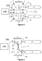
- a DC power grid according to an embodiment of the invention is shown in Figure 1 and is designated generally by the reference numeral 200.
- the DC power grid 200 comprises a plurality of DC terminals 202, and a plurality of DC transmission paths 204.
- each DC terminal 202 is operatively connected to the DC side of a respective AC-DC converter 206, which in turn is connected to a respective AC electrical network 208,210.
- a first DC transmission path 204 is arranged to interconnect a first DC terminal 202 and a second DC terminal 202
- a second DC transmission path 204 is arranged to interconnect the first DC terminal 202 and a third DC terminal 202
- a third DC transmission path 204 is arranged to interconnect the third DC terminal 202 and a fourth DC terminal 202.
- Figure 1 shows further DC transmission paths 204 that are connected to the rest of the DC power grid 200.
- Each DC transmission path 204 includes a DC power transmission line 16,18,19. More particularly, the first DC transmission path 204 includes a first DC power transmission line 16, the second DC transmission path 204 includes a second DC power transmission line 18, the third DC transmission path 204 includes a third DC power transmission line 19, and each further DC transmission path 204 includes a respective further DC power transmission line (not shown).
- Each DC transmission path 204 further includes a switching apparatus, which is in the form of a disconnector 212.
- each switching apparatus can be operated to open to selectively block current from flowing in the corresponding DC transmission path 204 when the current flowing in the corresponding DC transmission path 204 is at a current threshold of zero or substantially zero.
- the DC power grid 200 further includes a plurality of active power electronic devices, each of which is connected in at least one of the plurality of DC transmission paths.
- Each active power electronic device is in the form of a current flow controller 10, the structure of which is shown in Figure 2 .
- the current flow controller 10 comprises a plurality of connecting points, and a current flow control unit.
- the plurality of connecting points defines a pair of first connecting points 12a, 12b and a pair of second connecting points 14a, 14b.
- the pair of first connecting points 12a,12b is connected in series with the first DC power transmission line 16
- the pair of second connecting points 14a,14b is connected in series with the second DC power transmission line 18.
- the current flow control unit includes first and second current flow control sub-units 20,22.
- the first current flow control sub-unit 20 includes a plurality of first switching elements 24 connected in parallel with a first capacitor 26 in a full-bridge arrangement
- the second current flow control sub-unit 22 includes a plurality of second switching elements 28 connected in parallel with a second capacitor 30 in a full-bridge arrangement.
- Each of the first and second switching elements 24,28 is constituted by a semiconductor device in the form of an Insulated Gate Bipolar Transistor (IGBT).
- IGBT Insulated Gate Bipolar Transistor
- Each of the first and second switching elements 24,28 also includes an anti-parallel diode 32 connected in parallel therewith.
- one or more switching elements may be or may include a different semiconductor device such as a gate turn-off thyristor, a field effect transistor, an insulated gate commutated thyristor, an injection-enhanced gate transistor, an integrated gate commutated thyristor or any other self-commutated semiconductor device connected in series or in parallel.
- a gate turn-off thyristor such as a field effect transistor, an insulated gate commutated thyristor, an injection-enhanced gate transistor, an integrated gate commutated thyristor or any other self-commutated semiconductor device connected in series or in parallel.
- each capacitor may be replaced by a different capacitor such as a fuel cell, a battery or any other capacitor capable of storing and releasing its electrical energy to provide a voltage.
- the first current flow control sub-unit 20 is connected in series between the pair of first connecting points 12a,12b, while the second current flow control sub-unit 22 is connected in series between the pair of second connecting points 14a,14b.
- the first current flow control sub-unit 20 is connected in series with the first DC power transmission line 16
- the second current flow control sub-unit 22 is connected in series with the second DC power transmission line 18.
- the series-connection between each current flow control sub-unit 20,22 and the corresponding DC power transmission line 16,18 means that each current flow control sub-unit 20,22 may have a voltage rating that is significantly lower than the voltage difference between the corresponding DC power transmission line 16,18 and ground.
- each current flow control sub-unit 20,22 is selectively bypassed or inserted into circuit with the corresponding DC power transmission line 16,18 by changing the state of the corresponding switching elements 24,28 of each current flow control sub-unit 20,22.
- each current flow control sub-unit 20,22 is bypassed when the corresponding switching elements 24,28 in each current flow control sub-unit 20,22 are configured to form a short circuit in each current flow control sub-unit 20,22.
- This causes the current I 1 ,I 2 in the corresponding DC power transmission line 16,18 to pass through the short circuit and bypass the capacitor, and so each current flow control sub-unit 20,22 injects a zero voltage drop V 1 ,V 2 across the corresponding pair of connecting points 12a,12b,14a,14b and in series with the corresponding DC power transmission line 16,18.
- each current flow control sub-unit 20,22 is inserted into circuit with the corresponding DC power transmission line 16,18 when the corresponding switching elements 24,28 in each current flow control sub-unit 20,22 are configured to allow the current I 1 ,I 2 in the corresponding DC power transmission line 16,18 to flow into and out of the capacitor 26,30.
- Each capacitor 26,30 then charges or discharges its stored energy so as to provide a non-zero voltage drop V1,V2.
- Each capacitor 26,30 may be inserted into circuit in either forward or reverse directions so as to inject a positive or negative voltage drop V 1 ,V 2 across the corresponding pair of connecting points 12a,12b,14a,14b and in series with the corresponding DC power transmission line 16,18.
- the injection of the non-zero voltage drop V 1 ,V 2 in this manner allows the current flow controller 10 to selectively vary an apparent impedance of each of the first and second DC transmission paths 204.
- each current flow control sub-unit 20,22 is able to provide a bidirectional voltage drop across the corresponding pair of connecting points 12a,12b,14a,14b and conduct current in two directions, i.e. each current flow control sub-unit 20,22 is able to operate in all four quadrants.
- the configuration of the switching elements 24,28 and the capacitor 26,30 in each current flow control sub-unit 20,22 permits each current flow control sub-unit 20,22 to selectively provide a voltage source.
- the first and second capacitors 26,30 are connected in parallel to electrically couple the first and second current flow control sub-units 20,22 to permit transfer of energy, in use, between the first and second current flow control sub-units 20,22.
- each switching element of the current flow control unit is operable to selectively establish a current path through the current flow control unit between the first and second DC power transmission lines 16,18.
- the DC power grid 200 further includes a detector 214 (e.g. a current sensor) configured to detect one or more faults in the plurality of DC transmission paths 204, and a control unit 216 to control opening and closing of each switching apparatus.
- the control unit 216 further includes a switching control unit 100 to control the switching of the switching elements 24,28 of the first and second current flow control sub-units 20,22.
- the functionality of the switching control unit 100 may instead be performed by a plurality of control components configured to perform different tasks (such as detection, location, operation and so on) associated with the switching of the switching elements 24,28 of the first and second current flow control sub-units 20,22.
- a plurality of components may be distributed about the DC power grid 200, optionally with the parts associated with the detection, location and operation functions being located at a respective load current controller.
- the DC power grid 200 is used to transfer power, for example, from offshore wind farms 208 to on-shore AC systems 210 via the converters 206 and DC transmission paths 204.
- a fault or other abnormal operating condition may occur in the DC power grid 200.
- one of the DC power transmission lines 16,18,19 of the DC power grid 200 may experience a pole-to-ground fault.
- the presence of the fault or other abnormal operating condition may result in a high fault current in the faulty DC power transmission line 16,18,19 and therefore in the DC power grid 200.
- the current flow controller 10 may be operated to force a current in a faulty DC power transmission line 16,18,19 to reduce to a target current level that corresponds to the current threshold of zero or substantially zero at which the switching apparatus can be operated to block current from flowing in the corresponding DC transmission path 204.
- the target current level is zero or substantially zero for a disconnector 212.
- the first DC power transmission line 16 is the faulty DC power transmission line, but it will be understood that the following description of the working of the invention applies mutatis mutandis to a fault occurring in any of the other DC power transmission lines 18,19.
- the switching control unit 100 controls switching of each switching element 24,28 of the current flow control unit to selectively establish the current path through the current flow control unit between the first and second DC power transmission lines 16,18 as follows.
- the switching control unit 100 switches the first switching elements 24 of the first current flow control sub-unit 20 to inject a first non-zero voltage drop V 1 in series with the first DC power transmission line 16.
- the direction of the first non-zero voltage drop V 1 is set so that the application of the first non-zero voltage drop V 1 in series with the first DC power transmission line 16 creates a positive resistance effect in which the first non-zero voltage drop V 1 opposes and thereby reduces the current I 1 flowing in the first DC power transmission line 16.
- the apparent impedance of the first DC power transmission line 16 is varied to force the fault current I 1 flowing in the first DC transmission path 204 to reduce to the target current level.
- the switching control unit 100 switches the second switching elements 28 of the second current flow control sub-unit 22 to inject a second non-zero voltage drop V 2 in series with the second DC power transmission line 18.
- the direction of the second non-zero voltage drop V 2 is set so that the application of the second non-zero voltage drop V2 in series with the second DC power transmission line 18 creates a negative resistance effect in which the second non-zero voltage drop V 2 contributes to an increase of the current I 2 flowing in the second DC power transmission line 18.
- the application of the first and second non-zero voltage drops V 1 ,V 2 together with the electrical coupling between the first and second current flow control sub-units 20,22 allows energy to be transferred between the DC power transmission lines 16,18 via the current flow control unit.
- energy E 1 is removed from the first DC power transmission line 16 that is undergoing a reduction in current I1 and this energy E 1 is added to the second DC power transmission line 18 that is undergoing an increase in current I 2 by way of energy diversion through the current flow control unit.
- the energy E1 diverted by the current flow control unit from the first DC power transmission line 16 is preferably equal to the energy E 2 diverted by the current flow control unit into the second DC power transmission line 18 so as to minimise dissipation losses during the diversion of energy by the current flow control unit.
- the switching control unit 100 controls switching of each switching element 24,28 of the current flow control unit to selectively establish the current path through the current flow control unit and to selectively connect each capacitor between the first and second DC power transmission lines 16,18 in order to inject a voltage drop V1,V2, in use, into each of the DC transmission paths 204 and thereby direct current through the current path from the first DC transmission path 16 to the second DC transmission path 18 so as to force the fault current I1 in the faulty DC power transmission line 16 to reduce to the target current level.
- control unit 216 When the fault current I1 in the first DC power transmission line 16 is reduced to the target current level of zero or substantially zero, the control unit 216 operates the switching apparatus connected at both ends of the first DC transmission path 204 to open and thereby block current from flowing in the faulty first DC transmission path 204.
- the switching control unit 100 may coordinate the operation of multiple current flow controllers 10 to vary the apparent impedance of the first DC transmission path 204 so as to force the fault current I 1 flowing in the first DC power transmission line 16 to reduce to the target current level. This is achieved by operating the multiple current flow controllers 10 to inject a respective voltage drop V 1 into the first DC transmission path 204 such that the combination of the injected voltage drops V 1 is sufficiently high to reduce the fault current I 1 in the first DC power transmission line 16 to the target current level.
- the manner in which the current flow controller 10 is operated to force the fault current I 1 in the first DC power transmission line 16 to reduce to the target current level of zero or substantially zero by way of directing current away from the faulty DC power transmission line 16 means that it is only necessary for each current flow controller 10 to have information about the direction in which the fault lies, and not the exact location of the fault.
- Figures 5 and 6 illustrate the application of the current flow controller of Figure 2 to a three terminal meshed DC power grid.
- the meshed DC power grid includes three DC terminals, each of which is connected to the other two DC terminals via a respective DC power transmission line. More specifically, a first DC power transmission line interconnects first and second DC terminals, a second DC power transmission line interconnects the first DC terminal and a third DC terminal, and a third DC power transmission line interconnects the second and third DC terminals.
- the current flow controller 10 is connected between the first and second DC power transmission lines.
- a first converter is in the form of a rectifier that interconnects the first DC terminal and an AC electrical power source, e.g. an off-shore wind farm, and each of the second and third converters are in the form of inverters connected to a respective AC electrical network, e.g. an AC power grid.
- the operating points OP1,OP2 of the second and third converters are determined in accordance with respective voltage droop control characteristics in order to maintain the DC grid voltage at a desired level, and the first converter is in constant voltage control.
- each of the converters are operating at the same DC voltage Vdc, and so the currents I dc_1 ,I dc_2 flowing in the first and second DC power transmission lines are determined in accordance with the respective voltage drop characteristics.
- the current I ordR flowing in the first converter is the sum of the currents I dc_1 ,I dc_2 f lowing in first and second DC power transmission lines.
- the current flow controller 10 When a fault occurs in the first DC power transmission line, the current flow controller 10 is operated in the manner described above to respectively inject first and second non-zero voltage drops V 1 ,V 2 in series with the first and second DC power transmission lines. This creates a disparity in the respective DC voltages V dc_1 ,V dc_2 at the second and third converters.
- the disparity in the respective DC voltages V dc_1 ,V dc_2 at the second and third converters results in corresponding changes in the currents I dc_1 ,I dc_2 flowing in the first and second DC power transmission lines, as shown in Figure 6 .
- the changes in the currents I dc_1 ,I dc_2 flowing in the first and second DC power transmission lines occur by way of current being directed through the current path established through the current flow controller 10 from the first DC power transmission line to the second DC power transmission line.
- the operating voltage V and current I ordR of the first converter remains unchanged, and so the total power flow from the first converter into the meshed DC power grid remains unchanged.
- the magnitude of the injected first and second non-zero voltage drops V 1 , V 2 can be increased to suitable values so as to force a fault current in the faulty, first DC power transmission line 16 to reduce to the target current level, namely zero or substantially zero.
- a switching apparatus can be operated to disconnect the first DC power transmission line.
- the current flow controller in Figure 2 may be replaced by another current flow controller, as shown in Figure 4 , in which:
- first and second current flow control sub-units 20,22 share the same first capacitor 26.
- the first capacitor 26 is selectively bypassed or inserted into circuit with the respective DC power transmission line 16,18 by changing the state of the corresponding switching elements 24,28 of each current flow control sub-unit 20,22.
- the first capacitor 26 of the first current flow controller 110 is bypassed in a similar manner as the capacitor 26,30 of each current flow control sub-unit 20,22 of the aforementioned current flow controller 10, as described above.
- the first capacitor 26 is inserted into circuit with the respective DC power transmission line 16,18 when the switching elements 24,28 in each current flow control sub-unit 20,22 are configured to allow the current I 1 ,I 2 in the corresponding DC power transmission line 16,18 to flow into and out of the first capacitor 26.
- the first capacitor 26 then charges or discharges its stored energy so as to provide a non-zero voltage drop V 1 ,V 2 .
- the first capacitor 26 may be inserted into circuit with the respective DC power transmission line 16,18 in either forward or reverse directions so as to inject a positive or negative voltage drop V 1 ,V 2 across the corresponding pair of terminals 12a,12b,14a,14b and in series with the respective DC power transmission line 16,18.
- Sharing the same first capacitor 26 result s in the first and second current flow control sub-units 20,22 being electrically coupled and thereby allows energy to be transferred between the first and second current flow control sub-units 20,22.
- each DC power transmission line 16,18,19 may be replaced by, but is not limited to, a submarine DC power transmission cable, an overhead DC power transmission cable, an underground DC power transmission cable, or any DC power transmission medium of transmitting electrical power between two or more electrical elements.
- topology of the DC power grid 200 and current flow controllers 10 were merely chosen to illustrate the working of the invention and that the invention is applicable to other topologies of the DC power grid and active power electronic devices.
Landscapes
- Direct Current Feeding And Distribution (AREA)
Claims (12)
- Réseau électrique CC (200) comprenant : une pluralité de bornes CC (202), chaque borne CC pouvant être connectée de manière fonctionnelle à un convertisseur (206) ; et une pluralité de chemins de transmission CC (204), chaque chemin de transmission CC (204) étant agencé pour interconnecter deux ou plus de la pluralité de bornes CC (202), chaque chemin de transmission CC (204), incluant un support de transmission d'énergie CC (16, 18, 19), chaque chemin de transmission CC (204) incluant en outre un appareil de commutation pouvant fonctionner pour empêcher de manière sélective un courant de circuler dans le chemin de transmission CC correspondant (204), le réseau électrique CC (200) incluant en outre :au moins un dispositif électronique d'énergie active connecté dans au moins un de la pluralité de chemins de transmission CC (204), le ou chaque dispositif électronique d'énergie active étant configuré pour pouvoir fonctionner pour faire varier de manière sélective une impédance apparente du ou de chaque chemin de transmission CC correspondant (204) ; etun détecteur (214) configuré pour détecter une ou plusieurs défaillances survenant dans la pluralité de chemins de transmission CC (204) ;le réseau électrique CC (200) inclut en outre une unité de commande (216) programmée pour faire fonctionner le ou chaque dispositif électronique d'énergie active pour faire varier une impédance apparente d'un chemin de transmission CC correspondant défaillant (204) afin de forcer un courant (I1) circulant dans le chemin de transmission CC correspondant défaillant (204) à se réduire pour arriver à un niveau de courant cible, l'unité de commande (216) étant programmée en outre pour faire fonctionner le ou chaque appareil de commutation pour empêcher le courant de circuler dans le chemin de transmission CC correspondant défaillant (204) lorsque le courant circulant dans le chemin de transmission CC correspondant défaillant (204) est réduit pour arriver au niveau de courant cible, dans lequel le niveau de courant cible correspond à un seuil de courant auquel ou en dessous duquel l'appareil de commutation peut fonctionner pour empêcher le courant de circuler dans le chemin de transmission CC correspondant (204), caractérisé en ce quele ou chaque dispositif électronique d'énergie active est configuré pour pouvoir fonctionner pour faire varier de manière sélective une impédance apparente du ou de chaque chemin de transmission CC correspondant (204) et ainsi diriger le courant d'au moins un des chemins de transmission CC (204) vers au moins un autre de la pluralité de chemins de transmission CC (204), et l'unité de commande (216) est programmée pour faire fonctionner le ou chaque dispositif électronique d'énergie active pour faire varier une impédance apparente du chemin de transmission CC correspondant défaillant (204) et ainsi détourner le courant d'au moins un de la pluralité de chemins de transmission CC (204) vers au moins un autre de la pluralité de chemins de transmission CC (204) afin de forcer un courant circulant dans le chemin de transmission CC correspondant défaillant (204) à se réduire pour arriver au niveau de courant cible.
- Réseau électrique CC (200) selon la revendication 1, dans lequel le niveau de courant cible est nul ou sensiblement nul.
- Réseau électrique CC (200) selon une quelconque revendication précédente dans lequel l'appareil de commutation est un sectionneur (212) ou un isolateur.
- Réseau électrique CC (200) selon une quelconque revendication précédente dans lequel le ou chaque dispositif électronique d'énergie active est configuré pour pouvoir fonctionner pour injecter de manière sélective une chute de tension (V1, V2) dans le ou chaque chemin de transmission CC correspondant (204) et ainsi faire varier une impédance apparente du ou de chaque chemin de transmission CC correspondant (204).
- Réseau électrique CC (200) selon une quelconque revendication précédente incluant une pluralité de dispositifs électroniques d'énergie active, dans lequel l'unité de commande (216) est programmée pour coordonner le fonctionnement de la pluralité de dispositifs électroniques d'énergie active pour faire varier une impédance apparente d'un chemin de transmission CC correspondant défaillant (204) de manière à forcer un courant circulant dans le chemin de transmission CC correspondant défaillant (204) à se réduire pour arriver au niveau de courant cible.
- Réseau électrique CC (200) selon une quelconque revendication précédente dans lequel le ou chaque dispositif électronique de puissance active est un dispositif de commande de débit de courant (10) qui inclut :une pluralité de points de connexion (12a, 12b, 14a, 14b), chaque point de connexion (12a, 12b, 14a, 14b) étant connecté dans au moins un des chemins de transmission CC (204) ; etun dispositif de commande de débit de courant (10) interconnectant la pluralité de points de connexion (12a, 12b, 14a, 14b), le dispositif de commande de débit de courant (10) incluant une pluralité de sous-unités de commande de débit de courant interconnectées (20, 22), chacune de celles-ci étant, lors de l'utilisation, connectée dans un chemin de transmission DC respectif (204), chaque sous-unité de commande de débit de courant (20, 22) incluant au moins un élément de commutation (24, 28), le ou chaque élément de commutation (24, 28) de chaque sous-unité de dispositif de commande de débit de courant (20, 22) pouvant fonctionner pour établir de manière sélective un chemin de courant à travers le dispositif de commande de débit de courant (10) entre au moins un chemin de transmission CC (204) et au moins un autre chemin de transmission CC (204), et le ou chaque élément de commutation (24, 28) étant en outre connecté à au moins un dispositif de stockage d'énergie (26, 30) pour fournir de manière sélective une source de tension,dans lequel l'unité de commande (216) est ou inclut une unité de commande de commutation (100) pour commander la commutation de chaque élément de commutation (24, 28) du dispositif de commande de débit de courant (10) pour établir de manière sélective ledit chemin de courant à travers le dispositif de commande de débit de courant (10) et pour connecter de manière sélective le ou chaque dispositif de stockage d'énergie (26, 30) entre ledit au moins un chemin de transmission CC (204) et ledit au moins un autre chemin de transmission CC (204) de façon à injecter une chute de tension (V1, V2), lors de l'utilisation, à l'intérieur d'au moins un des chemins de transmission CC (204) et ainsi diriger le courant à travers le chemin de courant entre ledit au moins un chemin de transmission CC (204) et ledit au moins un autre chemin de transmission CC (204) afin de forcer le courant dans le chemin de transmission CC correspondant défaillant (204) à se réduire pour arriver au niveau de courant cible.
- Procédé d'élimination de défaillances pour un réseau électrique CC (200), dans lequel le réseau électrique CC (200) inclut: une pluralité de bornes CC (202), chaque borne CC pouvant être connectée de manière fonctionnelle à un convertisseur (206) ; et une pluralité de chemins de transmission CC (204), chaque chemin de transmission CC (204) étant agencé pour interconnecter deux ou plus de la pluralité de bornes CC (202), chaque chemin de transmission CC (204) incluant un support de transmission d'énergie CC (16, 18, 19), chaque chemin de transmission CC (204) incluant en outre un appareil de commutation pouvant fonctionner pour empêcher de manière sélective le courant de circuler dans le chemin de transmission CC correspondant (204), le réseau électrique CC (200) incluant en outre au moins un dispositif électronique d'énergie active connecté dans au moins un de la pluralité de chemins de transmission CC (204), le ou chaque dispositif électronique d'énergie active étant configuré pour pouvoir fonctionner pour faire varier de manière sélective une impédance apparente du ou de chaque chemin de transmission CC correspondant (204), dans lequel le procédé comprend l'étape consistant à :(i) détecter une défaillance survenant dans un ou plusieurs de la pluralité de chemins de transmission CC (204) ;
le procédé inclut en outre les étapes consistant à :(ii) après avoir détecté la défaillance survenant dans une ou plusieurs de la pluralité de chemins de transmission CC (204), faire fonctionner le ou chaque dispositif électronique d'énergie active pour faire varier une impédance apparente d'un chemin de transmission CC défaillant correspondant (204) de manière à forcer un courant circulant dans le chemin de transmission CC défaillant correspondant (204) à se réduire pour arriver à un niveau de courant cible ; et(iii) faire fonctionner le ou de chaque appareil de commutation pour empêcher le courant de circuler dans le chemin de transmission CC correspondant défaillant (204) lorsque le courant circulant dans le chemin de transmission CC correspondant défaillant (204) est réduit pour arriver au niveau de courant cible,
dans lequel le niveau de courant cible correspond à un seuil de courant auquel ou en dessous duquel l'appareil de commutation peut fonctionner pour empêcher le courant de circuler dans le chemin de transmission CC correspondant (204),
caractérisé en ce que
le ou chaque dispositif électronique d'énergie active est configuré pour pouvoir fonctionner pour faire varier de manière sélective une impédance apparente du ou de chaque chemin de transmission CC correspondant (204) et ainsi diriger le courant d'au moins un des chemins de transmission CC (204) vers au moins un autre de la pluralité de chemins de transmission CC (204), dans lequel le procédé inclut l'étape consistant à faire fonctionner le ou chaque dispositif électronique d'énergie active pour faire varier une impédance apparente du chemin de transmission CC correspondant défaillant (204) et ainsi détourner le courant d'au moins un de la pluralité de chemins de transmission CC (204) vers au moins un autre de la pluralité de chemins de transmission CC (204) afin de forcer un courant circulant dans le chemin de transmission CC correspondant défaillant (204) à se réduire pour arriver au niveau de courant cible. - Procédé selon la revendication 7 dans lequel le niveau de courant cible est nul ou sensiblement nul.
- Procédé selon la revendication 7 ou la revendication 8 dans lequel l'appareil de commutation est un sectionneur (212) ou un isolateur.
- Procédé selon l'une quelconque des revendications 7 à 9
dans lequel le ou chaque dispositif électronique d'énergie active est configuré pour pouvoir fonctionner pour injecter de manière sélective une chute de tension (V1, V2) dans le ou chaque chemin de transmission CC correspondant (204) et ainsi faire varier une impédance apparente du ou de chaque chemin de transmission CC correspondant (204). - Procédé selon l'une quelconque des revendications 7 à 10
dans lequel le réseau électrique CC (200) inclut une pluralité de dispositifs électroniques d'énergie active, dans lequel le procédé inclut l'étape consistant à coordonner le fonctionnement de la pluralité de dispositifs électroniques d'énergie active pour faire varier une impédance apparente d'un chemin de transmission CC correspondant défaillant (204) de manière à forcer un courant circulant dans le chemin de transmission CC correspondant défaillant (204) à se réduire pour arriver au niveau de courant cible. - Procédé selon l'une quelconque des revendications 7 à 11
dans lequel le ou chaque dispositif électronique de puissance active est un dispositif de commande de débit de courant (10) qui inclut :une pluralité de points de connexion (12a, 12b, 14a, 14b), chaque point de connexion (12a, 12b, 14a, 14b) étant connecté dans au moins un des chemins de transmission CC (204) ; etun dispositif de commande de débit de courant (10) interconnectant la pluralité de points de connexion (12a, 12b, 14a, 14b), le dispositif de commande de débit de courant (10) incluant une pluralité de sous-unités de commande de débit de courant interconnectées (20, 22), chacune de celles-ci étant, lors de l'utilisation, connectée dans un chemin de transmission DC respectif (204), chaque sous-unité de commande de débit de courant (20, 22) incluant au moins un élément de commutation (24, 28), le ou chaque élément de commutation (24, 28) de chaque sous-unité de dispositif de commande de débit de courant (20, 22) pouvant fonctionner pour établir de manière sélective un chemin de courant à travers le dispositif de commande de débit de courant (10) entre au moins un chemin de transmission CC (204) et au moins un autre chemin de transmission CC (204), et le ou chaque élément de commutation (24, 28) étant en outre connecté à au moins un dispositif de stockage d'énergie (26, 30) pour fournir de manière sélective une source de tension,dans lequel le procédé inclut l'étape consistant à commander la commutation de chaque élément de commutation (24, 28) du dispositif de commande de débit de courant (10) pour établir de manière sélective ledit chemin de courant à travers le dispositif de commande de débit de courant (10) et pour connecter de manière sélective le ou chaque dispositif de stockage d'énergie (26, 30) entre ledit au moins un chemin de transmission CC (204) et ledit au moins un autre chemin de transmission CC (204) de façon à injecter une chute de tension (V1, V2), lors de l'utilisation, à l'intérieur d'au moins un des chemins de transmission CC (204) et ainsi diriger le courant à travers le chemin de courant entre ledit au moins un chemin de transmission CC (204) et ledit au moins un autre chemin de transmission CC (204) afin de forcer le courant dans le chemin de transmission CC correspondant défaillant (204) à se réduire pour arriver au niveau de courant cible.
Priority Applications (4)
| Application Number | Priority Date | Filing Date | Title |
|---|---|---|---|
| EP14275256.7A EP3032677B1 (fr) | 2014-12-12 | 2014-12-12 | Réseau électrique à courant continu |
| CN201580068703.0A CN107112745B (zh) | 2014-12-12 | 2015-12-10 | 直流电力网络 |
| US15/535,296 US10700514B2 (en) | 2014-12-12 | 2015-12-10 | DC electrical network |
| PCT/EP2015/079305 WO2016092038A1 (fr) | 2014-12-12 | 2015-12-10 | Réseau électrique en courant continu |
Applications Claiming Priority (1)
| Application Number | Priority Date | Filing Date | Title |
|---|---|---|---|
| EP14275256.7A EP3032677B1 (fr) | 2014-12-12 | 2014-12-12 | Réseau électrique à courant continu |
Publications (2)
| Publication Number | Publication Date |
|---|---|
| EP3032677A1 EP3032677A1 (fr) | 2016-06-15 |
| EP3032677B1 true EP3032677B1 (fr) | 2021-05-05 |
Family
ID=52102613
Family Applications (1)
| Application Number | Title | Priority Date | Filing Date |
|---|---|---|---|
| EP14275256.7A Active EP3032677B1 (fr) | 2014-12-12 | 2014-12-12 | Réseau électrique à courant continu |
Country Status (4)
| Country | Link |
|---|---|
| US (1) | US10700514B2 (fr) |
| EP (1) | EP3032677B1 (fr) |
| CN (1) | CN107112745B (fr) |
| WO (1) | WO2016092038A1 (fr) |
Families Citing this family (13)
| Publication number | Priority date | Publication date | Assignee | Title |
|---|---|---|---|---|
| GB2537850B (en) * | 2015-04-28 | 2019-09-11 | General Electric Technology Gmbh | Bipolar DC power transmission scheme |
| GB2540813A (en) | 2015-07-30 | 2017-02-01 | General Electric Technology Gmbh | Electrical assembly |
| GB2541465A (en) * | 2015-08-21 | 2017-02-22 | General Electric Technology Gmbh | Electrical assembly |
| DE102016202661A1 (de) * | 2016-02-22 | 2017-08-24 | Siemens Aktiengesellschaft | Vorrichtung zum Schalten eines Gleichstroms in einem Pol eines Gleichspannungsnetzes |
| CN106159987B (zh) * | 2016-06-30 | 2018-12-21 | 南京南瑞继保电气有限公司 | 一种直流电网拓扑及故障隔离系统快速恢复的方法 |
| DE102016212915A1 (de) | 2016-07-14 | 2018-01-18 | Siemens Aktiengesellschaft | Schaltanordnung sowie Verfahren zur Fehlerklärung |
| JP6856303B2 (ja) * | 2016-10-14 | 2021-04-07 | 一般財団法人電力中央研究所 | 直流送電設備 |
| EP3461062B1 (fr) * | 2017-09-22 | 2020-02-26 | General Electric Technology GmbH | Appareil de distribution de puissance |
| FR3083019B1 (fr) * | 2018-06-25 | 2020-07-10 | Supergrid Institute | Systeme comprenant un dispositif de controle de flux de puissance utilise pour controler la repartition des courants dans un reseau maille et des moyens de protection dudit dispositif |
| CN109066605B (zh) * | 2018-07-06 | 2019-10-29 | 国网浙江省电力有限公司电力科学研究院 | 直流输电系统正负极直流断路器的协调动作控制策略 |
| EP3675301A1 (fr) * | 2018-12-27 | 2020-07-01 | Siemens Aktiengesellschaft | Couplage électrique d'au moins deux équipements électriques connectés à un réseau d alimentation en énergie avec au moins une source d'énergie électrique connectée au réseau d'alimentation en énergie |
| US12081014B2 (en) | 2020-12-23 | 2024-09-03 | Hamilton Sundstrand Corporation | Fault clearing in midpoint grounded systems |
| GB202411493D0 (en) * | 2024-08-05 | 2024-09-18 | Rolls Royce Plc | Electrical power system and method of control |
Citations (1)
| Publication number | Priority date | Publication date | Assignee | Title |
|---|---|---|---|---|
| EP3107172A1 (fr) * | 2014-02-14 | 2016-12-21 | Mitsubishi Electric Corporation | Système de protection pour système de transmission d'énergie électrique cc, convertisseur ca/cc, et procédé de coupure de système de transmission d'énergie électrique cc |
Family Cites Families (5)
| Publication number | Priority date | Publication date | Assignee | Title |
|---|---|---|---|---|
| US8625315B2 (en) * | 2008-05-09 | 2014-01-07 | Etm Electromatic Inc | Inverter modulator with variable switching frequency |
| CN103503269B (zh) * | 2011-05-30 | 2016-12-07 | Abb研究有限公司 | 用于向电网分配电功率的系统 |
| WO2013115915A1 (fr) * | 2012-01-31 | 2013-08-08 | Atlantic Grid Operations A., Llc | Commande et protection d'un réseau d'alimentation c.c. |
| EP2670013B1 (fr) * | 2012-06-01 | 2016-09-21 | General Electric Technology GmbH | Régulateur de flux de courant |
| EP3138171B1 (fr) * | 2014-06-27 | 2020-02-26 | Siemens Aktiengesellschaft | Protection transitoire pour grille ccht à bornes multiples |
-
2014
- 2014-12-12 EP EP14275256.7A patent/EP3032677B1/fr active Active
-
2015
- 2015-12-10 CN CN201580068703.0A patent/CN107112745B/zh active Active
- 2015-12-10 WO PCT/EP2015/079305 patent/WO2016092038A1/fr not_active Ceased
- 2015-12-10 US US15/535,296 patent/US10700514B2/en active Active
Patent Citations (1)
| Publication number | Priority date | Publication date | Assignee | Title |
|---|---|---|---|---|
| EP3107172A1 (fr) * | 2014-02-14 | 2016-12-21 | Mitsubishi Electric Corporation | Système de protection pour système de transmission d'énergie électrique cc, convertisseur ca/cc, et procédé de coupure de système de transmission d'énergie électrique cc |
Also Published As
| Publication number | Publication date |
|---|---|
| US20170331281A1 (en) | 2017-11-16 |
| CN107112745B (zh) | 2020-06-16 |
| US10700514B2 (en) | 2020-06-30 |
| EP3032677A1 (fr) | 2016-06-15 |
| WO2016092038A1 (fr) | 2016-06-16 |
| CN107112745A (zh) | 2017-08-29 |
Similar Documents
| Publication | Publication Date | Title |
|---|---|---|
| EP3032677B1 (fr) | Réseau électrique à courant continu | |
| EP2856590B1 (fr) | Procédé d'élimination de panne | |
| EP2786479B1 (fr) | Convertisseur de puissance | |
| CN101297469B (zh) | 传输系统及其控制方法 | |
| EP2670013B1 (fr) | Régulateur de flux de courant | |
| EP2975723B1 (fr) | Régulateur de flux de courant | |
| EP3289654B1 (fr) | Système de transmission d'énergie en courant continu bipolaire | |
| EP3036813B1 (fr) | Protection électrique à coté ac dans un système à haute tension continu | |
| CN113508506A (zh) | 一种光伏发电系统、光伏逆变器及直流汇流箱 | |
| EP3018786B1 (fr) | Ensemble de commande d'écoulement de courant | |
| EP3251189B1 (fr) | Poste extérieur évolutif pour interconnecter des réseaux de distribution d'énergie en courant continu | |
| EP3338336B1 (fr) | Ensemble électrique | |
| EP3544141A1 (fr) | Agencement électrique | |
| EP3329506B1 (fr) | Équipement électrique | |
| WO2015039942A1 (fr) | Module | |
| EP3007301A1 (fr) | Régulateur de flux de courant | |
| EP3007300A1 (fr) | Régulateur de flux de courant |
Legal Events
| Date | Code | Title | Description |
|---|---|---|---|
| PUAI | Public reference made under article 153(3) epc to a published international application that has entered the european phase |
Free format text: ORIGINAL CODE: 0009012 |
|
| AK | Designated contracting states |
Kind code of ref document: A1 Designated state(s): AL AT BE BG CH CY CZ DE DK EE ES FI FR GB GR HR HU IE IS IT LI LT LU LV MC MK MT NL NO PL PT RO RS SE SI SK SM TR |
|
| AX | Request for extension of the european patent |
Extension state: BA ME |
|
| STAA | Information on the status of an ep patent application or granted ep patent |
Free format text: STATUS: REQUEST FOR EXAMINATION WAS MADE |
|
| 17P | Request for examination filed |
Effective date: 20161215 |
|
| RBV | Designated contracting states (corrected) |
Designated state(s): AL AT BE BG CH CY CZ DE DK EE ES FI FR GB GR HR HU IE IS IT LI LT LU LV MC MK MT NL NO PL PT RO RS SE SI SK SM TR |
|
| STAA | Information on the status of an ep patent application or granted ep patent |
Free format text: STATUS: EXAMINATION IS IN PROGRESS |
|
| 17Q | First examination report despatched |
Effective date: 20181031 |
|
| RIC1 | Information provided on ipc code assigned before grant |
Ipc: H02H 7/28 20060101ALI20201016BHEP Ipc: H02H 7/26 20060101AFI20201016BHEP Ipc: H02H 3/02 20060101ALN20201016BHEP |
|
| RIC1 | Information provided on ipc code assigned before grant |
Ipc: H02H 3/02 20060101ALN20201029BHEP Ipc: H02H 7/26 20060101AFI20201029BHEP Ipc: H02H 7/28 20060101ALI20201029BHEP |
|
| GRAP | Despatch of communication of intention to grant a patent |
Free format text: ORIGINAL CODE: EPIDOSNIGR1 |
|
| STAA | Information on the status of an ep patent application or granted ep patent |
Free format text: STATUS: GRANT OF PATENT IS INTENDED |
|
| RIC1 | Information provided on ipc code assigned before grant |
Ipc: H02H 3/02 20060101ALN20201112BHEP Ipc: H02H 7/28 20060101ALI20201112BHEP Ipc: H02H 7/26 20060101AFI20201112BHEP |
|
| INTG | Intention to grant announced |
Effective date: 20201204 |
|
| GRAS | Grant fee paid |
Free format text: ORIGINAL CODE: EPIDOSNIGR3 |
|
| GRAA | (expected) grant |
Free format text: ORIGINAL CODE: 0009210 |
|
| STAA | Information on the status of an ep patent application or granted ep patent |
Free format text: STATUS: THE PATENT HAS BEEN GRANTED |
|
| AK | Designated contracting states |
Kind code of ref document: B1 Designated state(s): AL AT BE BG CH CY CZ DE DK EE ES FI FR GB GR HR HU IE IS IT LI LT LU LV MC MK MT NL NO PL PT RO RS SE SI SK SM TR |
|
| REG | Reference to a national code |
Ref country code: GB Ref legal event code: FG4D |
|
| REG | Reference to a national code |
Ref country code: CH Ref legal event code: EP |
|
| REG | Reference to a national code |
Ref country code: AT Ref legal event code: REF Ref document number: 1391026 Country of ref document: AT Kind code of ref document: T Effective date: 20210515 |
|
| REG | Reference to a national code |
Ref country code: DE Ref legal event code: R096 Ref document number: 602014077142 Country of ref document: DE |
|
| REG | Reference to a national code |
Ref country code: IE Ref legal event code: FG4D |
|
| REG | Reference to a national code |
Ref country code: SE Ref legal event code: TRGR |
|
| REG | Reference to a national code |
Ref country code: LT Ref legal event code: MG9D |
|
| REG | Reference to a national code |
Ref country code: AT Ref legal event code: MK05 Ref document number: 1391026 Country of ref document: AT Kind code of ref document: T Effective date: 20210505 |
|
| PG25 | Lapsed in a contracting state [announced via postgrant information from national office to epo] |
Ref country code: HR Free format text: LAPSE BECAUSE OF FAILURE TO SUBMIT A TRANSLATION OF THE DESCRIPTION OR TO PAY THE FEE WITHIN THE PRESCRIBED TIME-LIMIT Effective date: 20210505 Ref country code: BG Free format text: LAPSE BECAUSE OF FAILURE TO SUBMIT A TRANSLATION OF THE DESCRIPTION OR TO PAY THE FEE WITHIN THE PRESCRIBED TIME-LIMIT Effective date: 20210805 Ref country code: AT Free format text: LAPSE BECAUSE OF FAILURE TO SUBMIT A TRANSLATION OF THE DESCRIPTION OR TO PAY THE FEE WITHIN THE PRESCRIBED TIME-LIMIT Effective date: 20210505 Ref country code: FI Free format text: LAPSE BECAUSE OF FAILURE TO SUBMIT A TRANSLATION OF THE DESCRIPTION OR TO PAY THE FEE WITHIN THE PRESCRIBED TIME-LIMIT Effective date: 20210505 Ref country code: LT Free format text: LAPSE BECAUSE OF FAILURE TO SUBMIT A TRANSLATION OF THE DESCRIPTION OR TO PAY THE FEE WITHIN THE PRESCRIBED TIME-LIMIT Effective date: 20210505 |
|
| PG25 | Lapsed in a contracting state [announced via postgrant information from national office to epo] |
Ref country code: PL Free format text: LAPSE BECAUSE OF FAILURE TO SUBMIT A TRANSLATION OF THE DESCRIPTION OR TO PAY THE FEE WITHIN THE PRESCRIBED TIME-LIMIT Effective date: 20210505 Ref country code: PT Free format text: LAPSE BECAUSE OF FAILURE TO SUBMIT A TRANSLATION OF THE DESCRIPTION OR TO PAY THE FEE WITHIN THE PRESCRIBED TIME-LIMIT Effective date: 20210906 Ref country code: NO Free format text: LAPSE BECAUSE OF FAILURE TO SUBMIT A TRANSLATION OF THE DESCRIPTION OR TO PAY THE FEE WITHIN THE PRESCRIBED TIME-LIMIT Effective date: 20210805 Ref country code: ES Free format text: LAPSE BECAUSE OF FAILURE TO SUBMIT A TRANSLATION OF THE DESCRIPTION OR TO PAY THE FEE WITHIN THE PRESCRIBED TIME-LIMIT Effective date: 20210505 Ref country code: RS Free format text: LAPSE BECAUSE OF FAILURE TO SUBMIT A TRANSLATION OF THE DESCRIPTION OR TO PAY THE FEE WITHIN THE PRESCRIBED TIME-LIMIT Effective date: 20210505 Ref country code: GR Free format text: LAPSE BECAUSE OF FAILURE TO SUBMIT A TRANSLATION OF THE DESCRIPTION OR TO PAY THE FEE WITHIN THE PRESCRIBED TIME-LIMIT Effective date: 20210806 Ref country code: IS Free format text: LAPSE BECAUSE OF FAILURE TO SUBMIT A TRANSLATION OF THE DESCRIPTION OR TO PAY THE FEE WITHIN THE PRESCRIBED TIME-LIMIT Effective date: 20210905 Ref country code: LV Free format text: LAPSE BECAUSE OF FAILURE TO SUBMIT A TRANSLATION OF THE DESCRIPTION OR TO PAY THE FEE WITHIN THE PRESCRIBED TIME-LIMIT Effective date: 20210505 |
|
| REG | Reference to a national code |
Ref country code: NL Ref legal event code: MP Effective date: 20210505 |
|
| PG25 | Lapsed in a contracting state [announced via postgrant information from national office to epo] |
Ref country code: NL Free format text: LAPSE BECAUSE OF FAILURE TO SUBMIT A TRANSLATION OF THE DESCRIPTION OR TO PAY THE FEE WITHIN THE PRESCRIBED TIME-LIMIT Effective date: 20210505 |
|
| PG25 | Lapsed in a contracting state [announced via postgrant information from national office to epo] |
Ref country code: RO Free format text: LAPSE BECAUSE OF FAILURE TO SUBMIT A TRANSLATION OF THE DESCRIPTION OR TO PAY THE FEE WITHIN THE PRESCRIBED TIME-LIMIT Effective date: 20210505 Ref country code: SK Free format text: LAPSE BECAUSE OF FAILURE TO SUBMIT A TRANSLATION OF THE DESCRIPTION OR TO PAY THE FEE WITHIN THE PRESCRIBED TIME-LIMIT Effective date: 20210505 Ref country code: SM Free format text: LAPSE BECAUSE OF FAILURE TO SUBMIT A TRANSLATION OF THE DESCRIPTION OR TO PAY THE FEE WITHIN THE PRESCRIBED TIME-LIMIT Effective date: 20210505 Ref country code: DK Free format text: LAPSE BECAUSE OF FAILURE TO SUBMIT A TRANSLATION OF THE DESCRIPTION OR TO PAY THE FEE WITHIN THE PRESCRIBED TIME-LIMIT Effective date: 20210505 Ref country code: CZ Free format text: LAPSE BECAUSE OF FAILURE TO SUBMIT A TRANSLATION OF THE DESCRIPTION OR TO PAY THE FEE WITHIN THE PRESCRIBED TIME-LIMIT Effective date: 20210505 Ref country code: EE Free format text: LAPSE BECAUSE OF FAILURE TO SUBMIT A TRANSLATION OF THE DESCRIPTION OR TO PAY THE FEE WITHIN THE PRESCRIBED TIME-LIMIT Effective date: 20210505 |
|
| REG | Reference to a national code |
Ref country code: DE Ref legal event code: R097 Ref document number: 602014077142 Country of ref document: DE |
|
| PLBE | No opposition filed within time limit |
Free format text: ORIGINAL CODE: 0009261 |
|
| STAA | Information on the status of an ep patent application or granted ep patent |
Free format text: STATUS: NO OPPOSITION FILED WITHIN TIME LIMIT |
|
| 26N | No opposition filed |
Effective date: 20220208 |
|
| PG25 | Lapsed in a contracting state [announced via postgrant information from national office to epo] |
Ref country code: IS Free format text: LAPSE BECAUSE OF FAILURE TO SUBMIT A TRANSLATION OF THE DESCRIPTION OR TO PAY THE FEE WITHIN THE PRESCRIBED TIME-LIMIT Effective date: 20210905 Ref country code: AL Free format text: LAPSE BECAUSE OF FAILURE TO SUBMIT A TRANSLATION OF THE DESCRIPTION OR TO PAY THE FEE WITHIN THE PRESCRIBED TIME-LIMIT Effective date: 20210505 |
|
| PG25 | Lapsed in a contracting state [announced via postgrant information from national office to epo] |
Ref country code: MC Free format text: LAPSE BECAUSE OF FAILURE TO SUBMIT A TRANSLATION OF THE DESCRIPTION OR TO PAY THE FEE WITHIN THE PRESCRIBED TIME-LIMIT Effective date: 20210505 Ref country code: IT Free format text: LAPSE BECAUSE OF FAILURE TO SUBMIT A TRANSLATION OF THE DESCRIPTION OR TO PAY THE FEE WITHIN THE PRESCRIBED TIME-LIMIT Effective date: 20210505 |
|
| REG | Reference to a national code |
Ref country code: CH Ref legal event code: PL |
|
| REG | Reference to a national code |
Ref country code: BE Ref legal event code: MM Effective date: 20211231 |
|
| PG25 | Lapsed in a contracting state [announced via postgrant information from national office to epo] |
Ref country code: LU Free format text: LAPSE BECAUSE OF NON-PAYMENT OF DUE FEES Effective date: 20211212 Ref country code: IE Free format text: LAPSE BECAUSE OF NON-PAYMENT OF DUE FEES Effective date: 20211212 |
|
| PG25 | Lapsed in a contracting state [announced via postgrant information from national office to epo] |
Ref country code: BE Free format text: LAPSE BECAUSE OF NON-PAYMENT OF DUE FEES Effective date: 20211231 |
|
| PG25 | Lapsed in a contracting state [announced via postgrant information from national office to epo] |
Ref country code: LI Free format text: LAPSE BECAUSE OF NON-PAYMENT OF DUE FEES Effective date: 20211231 Ref country code: CH Free format text: LAPSE BECAUSE OF NON-PAYMENT OF DUE FEES Effective date: 20211231 |
|
| PG25 | Lapsed in a contracting state [announced via postgrant information from national office to epo] |
Ref country code: HU Free format text: LAPSE BECAUSE OF FAILURE TO SUBMIT A TRANSLATION OF THE DESCRIPTION OR TO PAY THE FEE WITHIN THE PRESCRIBED TIME-LIMIT; INVALID AB INITIO Effective date: 20141212 |
|
| P01 | Opt-out of the competence of the unified patent court (upc) registered |
Effective date: 20230522 |
|
| PG25 | Lapsed in a contracting state [announced via postgrant information from national office to epo] |
Ref country code: CY Free format text: LAPSE BECAUSE OF FAILURE TO SUBMIT A TRANSLATION OF THE DESCRIPTION OR TO PAY THE FEE WITHIN THE PRESCRIBED TIME-LIMIT Effective date: 20210505 |
|
| PG25 | Lapsed in a contracting state [announced via postgrant information from national office to epo] |
Ref country code: MK Free format text: LAPSE BECAUSE OF FAILURE TO SUBMIT A TRANSLATION OF THE DESCRIPTION OR TO PAY THE FEE WITHIN THE PRESCRIBED TIME-LIMIT Effective date: 20210505 |
|
| PG25 | Lapsed in a contracting state [announced via postgrant information from national office to epo] |
Ref country code: TR Free format text: LAPSE BECAUSE OF FAILURE TO SUBMIT A TRANSLATION OF THE DESCRIPTION OR TO PAY THE FEE WITHIN THE PRESCRIBED TIME-LIMIT Effective date: 20210505 |
|
| PG25 | Lapsed in a contracting state [announced via postgrant information from national office to epo] |
Ref country code: MT Free format text: LAPSE BECAUSE OF FAILURE TO SUBMIT A TRANSLATION OF THE DESCRIPTION OR TO PAY THE FEE WITHIN THE PRESCRIBED TIME-LIMIT Effective date: 20210505 |
|
| PGFP | Annual fee paid to national office [announced via postgrant information from national office to epo] |
Ref country code: DE Payment date: 20251126 Year of fee payment: 12 |
|
| PGFP | Annual fee paid to national office [announced via postgrant information from national office to epo] |
Ref country code: GB Payment date: 20251119 Year of fee payment: 12 |
|
| PGFP | Annual fee paid to national office [announced via postgrant information from national office to epo] |
Ref country code: FR Payment date: 20251120 Year of fee payment: 12 |
|
| PGFP | Annual fee paid to national office [announced via postgrant information from national office to epo] |
Ref country code: SE Payment date: 20251119 Year of fee payment: 12 |