EP3032995B1 - Verbesserte vorrichtung zum waschen einer glasscheibe - Google Patents
Verbesserte vorrichtung zum waschen einer glasscheibe Download PDFInfo
- Publication number
- EP3032995B1 EP3032995B1 EP15714662.2A EP15714662A EP3032995B1 EP 3032995 B1 EP3032995 B1 EP 3032995B1 EP 15714662 A EP15714662 A EP 15714662A EP 3032995 B1 EP3032995 B1 EP 3032995B1
- Authority
- EP
- European Patent Office
- Prior art keywords
- dispensing
- duct
- liquid
- anyone
- glass
- Prior art date
- Legal status (The legal status is an assumption and is not a legal conclusion. Google has not performed a legal analysis and makes no representation as to the accuracy of the status listed.)
- Active
Links
Images
Classifications
-
- A—HUMAN NECESSITIES
- A47—FURNITURE; DOMESTIC ARTICLES OR APPLIANCES; COFFEE MILLS; SPICE MILLS; SUCTION CLEANERS IN GENERAL
- A47L—DOMESTIC WASHING OR CLEANING; SUCTION CLEANERS IN GENERAL
- A47L15/00—Washing or rinsing machines for crockery or tableware
- A47L15/0065—Washing or rinsing machines for crockery or tableware specially adapted for drinking glasses
Definitions
- the present invention relates to an improved device for washing a glass.
- the present device is conveniently used for externally rinsing and disinfecting the glasses intended to be subsequently filled with a beverage such as beer and the like.
- the glass to rinse must be, first, upside down and lean on said base.
- the nozzle which comes into operation, activating, delivers a jet of water against the internal surfaces of the glass.
- Said dispensing members are shaped so as to direct the water jet on the entire outer surface of the glass, also on the portions distant from the rim, these openings being distant from the supporting surface of the rim of the glass. In this way the glass is completely wet and the area near the rim, where the lips are laid is not disinfected directly by the jet, but only due to the fall of the water. This can result in a non-optimal disinfection of the rim of the glass.
- systems according to the prior art have very bulky dispensing members especially when they are installed in structures in which they are located. This implies that they are not easily adaptable to sinks or drains, even of small size, of pubs, bars and the like.
- object of the present invention to provide an improved device that allows to uniformly wet a glass, even on the outer surface and in particular on the rim.
- a further object of the present invention is to provide a device comprising a dispensing element which is compact and easily adaptable to different sinks or drains.
- Another object of the invention is to provide an improved device which allows to uniformly cool a glass.
- a further object of the present invention is to provide an improved device for wetting a glass that is inexpensive and simple to manufacture.
- a device for washing a glass comprising a supply duct of a washing liquid, at least one dispensing member comprising at least one ring-shaped dispensing duct having at least one hole for the emission of a jet of said liquid, at least two radial connecting ducts, which connect said dispensing duct to said supply duct, said at least two radial connecting ducts laying on the same plane of said dispensing duct, so as to be capable of supporting the rim of said glass when it is turned upside down, so that said at least one hole of said dispensing duct can emit a jet of liquid on the outer surface portion of said glass, and means for interrupting the flow, for selectively interrupting the passage of said liquid through said supply duct or through said dispensing duct.
- said supply duct comprises a support, having an internal cavity for the passage of said liquid, and in that it comprises connecting means to mutually connect said internal cavity and said at least one hole.
- said at least one hole is configured so as to emit a liquid jet according to a predetermined trajectory which forms an angle with said predetermined radius comprised between 0 and 90 degrees.
- said dispensing duct is a ring with a substantially circular shape.
- said connecting means comprise a circumferential inner cavity obtained in said dispensing duct, so as to form a toroid.
- said supply duct could have a plurality of holes.
- said device could comprise at least one nozzle manually adjustable on each of said holes, to direct the respective jet of liquid.
- said dispensing duct is arranged substantially perpendicular with respect to said supply duct.
- said device could comprise a further delivery hole to deliver a jet of said liquid according to a predetermined direction passing within said dispensing element, said dispensing duct being in communication with said supply duct and being arranged substantially on the plane in which said radial connecting ducts and said dispensing duct lie.
- said predetermined direction is an axial direction with respect to said dispensing duct.
- said means for interrupting the flow are configured to allow the passage of a liquid through said supply duct when a pressure equal to, or greater than a given threshold pressure value is exerted on said dispensing element.
- said means for interrupting the flow comprise a shutter, arranged in said inner cavity of said support, and a spring arranged between said shutter and said support.
- said connecting means comprise a supply duct incorporated in said shutter and communicating with said dispensing duct and with said inner cavity of said support when said flow interruption means are configured so as to allow the passage of a liquid through said internal cavity.
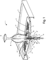
- FIG. 1 by reference number 1 it is indicated a device for wetting a glass according to the present invention.
- Said device 1 comprises a support base 2 integrated with a grid 3 for draining liquids to an underlying tank outflow 4, from which said liquids flow out towards a collecting member, not shown in the figure.
- Device 1 includes a dispensing device 5 formed by a support 6 having substantially the shape of a cylinder in which an axial through cavity 6' is formed.
- This support 6 is arranged so as to pass through a corresponding opening formed in said tank outflow 4, to which it is firmly anchored by means of suitable removable connecting means.
- a connecting member 10 is mounted, adapted to allow the connection of a water supply duct (not shown in the figure).
- Support 6 has, in correspondence of the axial through cavity 6', a narrowing 6", through which a substantially cylinder-shaped shutter 7 is enabled to slide.
- This shutter 7 provides, internally, with an axial feed duct 12 which flows on the top with an axial dispensing hole 12' directed according to a predetermined axial direction D, and communicating, at the bottom, with said axial through cavity 6' of the support 6 using at least one portion of the radial duct.
- a first ring seal 8a is housed, adapted to provide a seal between said shutter 7 and the narrowing 6" of the support 6.
- this shutter 7 has a head shutter 7' having a second ring seal 8b, arranged facing said narrowing 6" and configured to form a seal when said second seal 8b abuts with the lower part of said narrowing 6".
- the shutter 7 In correspondence of an intermediate axial position, the shutter 7 has a widened portion 7" in the radial direction.
- a spring 9 arranged between the narrowing 6" of said support 6 and the enlarged portion 7" of the shutter 7, in order to induce the ring seal 8 to abut on the bottom of said narrowing 6", so obstructing said axial through cavity 6'.
- the dispensing device 5 also comprises a dispensing duct 11, which in this embodiment is a circular-shaped ring, having a circumferential internal cavity 11' and arranged in correspondence with an opening 3' formed in the grid 3, substantially orthogonal with respect to the shutter 7.
- a dispensing duct 11 which in this embodiment is a circular-shaped ring, having a circumferential internal cavity 11' and arranged in correspondence with an opening 3' formed in the grid 3, substantially orthogonal with respect to the shutter 7.
- said dispensing duct 11 is mounted on an upper portion 7a of the shutter 7, axially projecting from the underlying support 6, through a plurality of radial connecting ducts 11a, so as to make mutually communicating the circumferential inner cavity 11' of said dispensing duct 11 and the axial supply duct 12 of the shutter 7, through said plurality of radial connecting ducts 11a.
- Said plurality of radial connecting ducts 11a is adapted to support the rim of the glass and lies on the same plane of said dispensing duct 11.
- said plurality of radial connecting ducts 11a is substantially coplanar with said dispensing duct 11, so as to be arranged in correspondence with said opening 3' formed in said grid 3.
- Said dispensing through holes 13 extend along an entire circumference of said dispensing duct 11 and are configured so as to deliver related fluid jets directed substantially towards said predetermined axial direction D.
- manually adjustable dispensing nozzle can be arranged (not shown in the figures), in order to better direct the respective jet of liquid.
- the device may include, further, a cooling system - not shown in the figure for simplicity of representation - arranged upstream of the support 6 and capable to cool the liquid before it passes through said support 6.
- connection member 10 For the operation of the device 1 it is required, first, connecting the support 6 to means for feeding water or other liquid, such as a solenoid pump, for example through a tube connected to the above mentioned connection member 10.
- the water being capable to freely flow in the axial supply duct 12, reaches the axial dispensing hole 12' and the through holes 13 formed in the ring dispensing duct 11, thus producing a jet of water substantially axially directed towards the inner surfaces of the glass B and a plurality of water jets directed toward the outer surfaces of said glass B, each according to a trajectory such as to form an angle with a radius of said dispensing duct 11 comprised between 0°and 90°.
- the glass B is wet both internally and externally.
- the rim of the glass B is positioned on said plurality of radial connecting ducts 11a, the water coming out from said supply through holes 13, formed in the dispensing duct 11, coplanar with said plurality of radial connecting ducts 11a, is conveyed directly on the rim of the glass B ensuring a selective washing.
- Glass B is possibly also cooled both on the inner surface for containing the liquid, and on the outside.
- the water that wets the glass B also determines a generalized and uniform cooling.
- the beer poured into a so wet and cooled glass will show an optimal quantity and quality of foam, so as to make its tasting more pleasant.
- a further advantage of this device is given by the cool sensation perceived by the consumer when leans his lips on the rim of the glass to drink the beer, or other beverage contained in this glass.
- the external cooling improves the effects of cooling inside the glass.
Landscapes
- Devices For Dispensing Beverages (AREA)
- Nozzles (AREA)
Claims (13)
- Vorrichtung (1) zum Reinigen eines Glases (B), umfassend
eine Zufuhrleitung (12) einer Reinigungsflüssigkeit,
mindestens ein Abgabeglied, umfassend
mindestens eine ringförmige Abgabeleitung (11), die mindestens ein Loch (13) für die Abgabe eines Strahls der Flüssigkeit aufweist, und
Mittel zum Unterbrechen des Flusses (7, 7', 8b), zum selektiven Unterbrechen des Durchlaufens einer Flüssigkeit,
dadurch gekennzeichnet, dass
die Vorrichtung (1) weiter mindestens zwei radiale Verbindungsleitungen (11a) umfasst, die die Abgabeleitung (11) mit der Zufuhrleitung (12) verbinden, wobei die mindestens zwei radialen Verbindungsleitungen (11a) auf derselben Ebene der Abgabeleitung (11) liegen, um in der Lage zu sein, den Rand des Glases (B) abzustützen, wenn es mit der Oberseite nach unten gedreht ist, sodass das mindestens eine Loch (13) der Abgabeleitung (11) einen Strahl der Flüssigkeit auf den Außenoberflächenbereich des Glases (B) emittieren kann, und
und dadurch, dass die Mittel zum Unterbrechen des Flusses (7, 7', 8b) selektiv das Durchlaufen der Flüssigkeit durch die Zufuhrleitung (12) oder durch die Abgabeleitung (11) hindurch unterbrechen. - Vorrichtung (1) nach Anspruch 1, dadurch gekennzeichnet, dass die Zufuhrleitung eine Stütze (6) umfasst, die einen internen Hohlraum (6') für das Durchlaufen der Flüssigkeit aufweist, und
dadurch, dass sie Verbindungsmittel (12, 11') umfasst, um gegenseitig den internen Hohlraum (6') und das mindestens eine Loch (13) zu verbinden. - Vorrichtung (1) nach einem der vorstehenden Ansprüche, dadurch gekennzeichnet, dass das mindestens eine Loch (13) dafür eingerichtet ist, einen Flüssigkeitsstrahl nach einer vorbestimmten Trajektorie zu emittieren, die einen Winkel mit dem vorbestimmten Radius bildet, der zwischen 0 und 90 Grad umfasst ist.
- Vorrichtung (1) nach einem der vorstehenden Ansprüche, dadurch gekennzeichnet, dass die Abgabeleitung (11) ein Ring mit einer im Wesentlichen kreisförmigen Form ist.
- Vorrichtung (1) nach einem der Ansprüche 2-4, dadurch gekennzeichnet, dass die Verbindungsmittel einen umlaufenden inneren Hohlraum (11') umfassen, der in der Abgabeleitung (11) erhalten ist, um einen Torus zu bilden.
- Vorrichtung (1) nach einem der vorstehenden Ansprüche, dadurch gekennzeichnet, dass die Zufuhrleitung (11) eine Vielzahl von Löchern (13) aufweist.
- Vorrichtung (1) nach einem der vorstehenden Ansprüche, dadurch gekennzeichnet, dass sie mindestens eine manuell einstellbare Düse an jedem der Löcher (13) umfasst, um den jeweiligen Flüssigkeitsstrahl auszurichten.
- Vorrichtung (1) nach einem der vorstehenden Ansprüche, dadurch gekennzeichnet, dass die Abgabeleitung (11) im Wesentlichen senkrecht in Bezug auf die Zufuhrleitung (12) angeordnet ist.
- Vorrichtung (1) nach einem der vorstehenden Ansprüche, dadurch gekennzeichnet, dass sie ein weiteres Lieferungsausgabeloch (12') umfasst, um einen Strahl der Flüssigkeit nach einer vorbestimmten Richtung (D) zu liefern, die innerhalb der Abgabeleitung (11) verläuft, wobei das Ausgabeloch (12') in Kommunikation mit der Zufuhrleitung (12) steht und im Wesentlichen auf der Ebene angeordnet ist, auf der die radialen Verbindungsleitungen (11a) und die Abgabeleitung (11) liegen.
- Vorrichtung (1) nach dem vorstehenden Anspruch, dadurch gekennzeichnet, dass die vorbestimmte Richtung (D) eine axiale Richtung in Bezug auf die Ausgabeleitung (11) ist.
- Vorrichtung (1) nach einem der vorstehenden Ansprüche, dadurch gekennzeichnet, dass die Mittel zum Unterbrechen des Flusses (7, 7', 8b) dafür eingerichtet sind, das Durchlaufen einer Flüssigkeit durch die Zufuhrleitung (12) zu erlauben, wenn ein Druck gleich oder größer einem gegebenen Schwellendruckwert auf die Abgabeleitung (11) ausgeübt wird.
- Vorrichtung (1) nach einem der vorstehenden Ansprüche, dadurch gekennzeichnet, dass die Mittel zum Unterbrechen des Flusses einen Verschluss (7), der in dem inneren Hohlraum (6') der Stütze (6) angeordnet ist, und eine Feder (9), die zwischen dem Verschluss (7) und der Stütze (6) angeordnet ist, umfassen.
- Vorrichtung (1) nach dem vorstehenden Anspruch, dadurch gekennzeichnet, dass die Verbindungsmittel eine Zufuhrleitung (12) umfassen, die in dem Verschluss (7) eingebaut ist und mit der Abgabeleitung (11) und mit dem inneren Hohlraum (6') der Stütze (12) kommuniziert, wenn die Flussunterbrechungsmittel (7, 7', 8b) dafür eingerichtet sind, das Durchlaufen einer Flüssigkeit durch den inneren Hohlraum (6') hindurch zu erlauben.
Applications Claiming Priority (2)
| Application Number | Priority Date | Filing Date | Title |
|---|---|---|---|
| ITRM20140025 | 2014-01-20 | ||
| PCT/IT2015/000007 WO2015107560A1 (en) | 2014-01-20 | 2015-01-20 | Improved device for washing a glass |
Publications (2)
| Publication Number | Publication Date |
|---|---|
| EP3032995A1 EP3032995A1 (de) | 2016-06-22 |
| EP3032995B1 true EP3032995B1 (de) | 2019-03-27 |
Family
ID=50349764
Family Applications (1)
| Application Number | Title | Priority Date | Filing Date |
|---|---|---|---|
| EP15714662.2A Active EP3032995B1 (de) | 2014-01-20 | 2015-01-20 | Verbesserte vorrichtung zum waschen einer glasscheibe |
Country Status (4)
| Country | Link |
|---|---|
| EP (1) | EP3032995B1 (de) |
| CA (1) | CA2918598C (de) |
| ES (1) | ES2730748T3 (de) |
| WO (1) | WO2015107560A1 (de) |
Families Citing this family (2)
| Publication number | Priority date | Publication date | Assignee | Title |
|---|---|---|---|---|
| US10914056B2 (en) | 2018-09-14 | 2021-02-09 | Delta Faucet Company | Vessel rinsing apparatus |
| CA3090252A1 (en) | 2019-08-19 | 2021-02-19 | Delta Faucet Company | Vessel rinsing apparatus, drain receptacle, interchangeable nozzle assembly, and faucet system including same |
Family Cites Families (7)
| Publication number | Priority date | Publication date | Assignee | Title |
|---|---|---|---|---|
| US378621A (en) * | 1888-02-28 | Tumbler or bottle washer | ||
| DE575301C (de) * | 1933-04-26 | Otto Wonneberger | Glaeserspuelvorrichtung | |
| US683111A (en) * | 1901-06-24 | 1901-09-24 | Joseph Fisher | Glass-washer. |
| FR355227A (fr) * | 1905-06-03 | 1905-10-26 | Charles Carpels | Rince-verre perfectionné |
| US981433A (en) * | 1910-11-15 | 1911-01-10 | Walter Lamb | Apparatus for holding and washing drinking vessels. |
| US1140698A (en) * | 1913-05-26 | 1915-05-25 | James F Merrigan | Glass-washer. |
| GB309878A (en) * | 1928-06-30 | 1929-04-25 | Robert Haimes | Improvements in or relating to appliances for washing drinking vessels and other like articles |
-
2015
- 2015-01-20 CA CA2918598A patent/CA2918598C/en active Active
- 2015-01-20 ES ES15714662T patent/ES2730748T3/es active Active
- 2015-01-20 WO PCT/IT2015/000007 patent/WO2015107560A1/en not_active Ceased
- 2015-01-20 EP EP15714662.2A patent/EP3032995B1/de active Active
Non-Patent Citations (1)
| Title |
|---|
| None * |
Also Published As
| Publication number | Publication date |
|---|---|
| CA2918598A1 (en) | 2015-07-23 |
| CA2918598C (en) | 2021-11-30 |
| EP3032995A1 (de) | 2016-06-22 |
| WO2015107560A1 (en) | 2015-07-23 |
| ES2730748T3 (es) | 2019-11-12 |
Similar Documents
| Publication | Publication Date | Title |
|---|---|---|
| CN203342966U (zh) | 一种用于水龙头的喷头组件 | |
| US8960080B2 (en) | Foaming nozzle | |
| CN105768892B (zh) | 用于饮料制备机的饮料出口 | |
| US10611619B2 (en) | Container for receiving beverages and device for filling the container | |
| JP6259106B2 (ja) | 発泡飲料および炭酸飲料を手動で注出するための器具 | |
| EP3032995B1 (de) | Verbesserte vorrichtung zum waschen einer glasscheibe | |
| EP2709776B1 (de) | Behälterreiniger | |
| WO2016110721A2 (en) | Improved water apparatus | |
| US20080142095A1 (en) | Faucet | |
| RU2607315C2 (ru) | Устройство для приготовления напитка с деформируемым выходным каналом | |
| EP2271865B1 (de) | Verteiler mit einem drehbaren u-förmigen verbindungskanal | |
| KR102241410B1 (ko) | 음료 주출 콕, 밸브 로드 및 음료 디스펜서 | |
| GB2582799A (en) | Spray head | |
| WO2015170294A1 (en) | Member to increase the thickness and the creaminess beverage in a beverage producing machine | |
| EP3429441A1 (de) | Maschine zur herstellung von brühgetränken mit emulgierender vorrichtung | |
| JP2017100769A (ja) | 炭酸水注出バルブ | |
| WO2020201675A1 (en) | Spray head | |
| EP3050470B1 (de) | Vorrichtung zum verlangsamen und halten kompakt den fluss von einem drink an der ausgang eines dispensers | |
| US20140027014A1 (en) | System for Reducing Foam at a Tap | |
| JP6210373B2 (ja) | 飲料用ディスペンサ | |
| EP3040799A1 (de) | Flüssigkeitsströmungsregler | |
| KR20160033474A (ko) | 관로 교체가 용이한 액체저장용기용 디스펜서 | |
| HK1226269B (zh) | 用於饮料制备机的饮料出口 | |
| CN105520642A (zh) | 饮料供应装置的多路阀 |
Legal Events
| Date | Code | Title | Description |
|---|---|---|---|
| PUAI | Public reference made under article 153(3) epc to a published international application that has entered the european phase |
Free format text: ORIGINAL CODE: 0009012 |
|
| 17P | Request for examination filed |
Effective date: 20160317 |
|
| AK | Designated contracting states |
Kind code of ref document: A1 Designated state(s): AL AT BE BG CH CY CZ DE DK EE ES FI FR GB GR HR HU IE IS IT LI LT LU LV MC MK MT NL NO PL PT RO RS SE SI SK SM TR |
|
| AX | Request for extension of the european patent |
Extension state: BA ME |
|
| DAX | Request for extension of the european patent (deleted) | ||
| GRAP | Despatch of communication of intention to grant a patent |
Free format text: ORIGINAL CODE: EPIDOSNIGR1 |
|
| STAA | Information on the status of an ep patent application or granted ep patent |
Free format text: STATUS: GRANT OF PATENT IS INTENDED |
|
| INTG | Intention to grant announced |
Effective date: 20181030 |
|
| GRAS | Grant fee paid |
Free format text: ORIGINAL CODE: EPIDOSNIGR3 |
|
| GRAA | (expected) grant |
Free format text: ORIGINAL CODE: 0009210 |
|
| STAA | Information on the status of an ep patent application or granted ep patent |
Free format text: STATUS: THE PATENT HAS BEEN GRANTED |
|
| AK | Designated contracting states |
Kind code of ref document: B1 Designated state(s): AL AT BE BG CH CY CZ DE DK EE ES FI FR GB GR HR HU IE IS IT LI LT LU LV MC MK MT NL NO PL PT RO RS SE SI SK SM TR |
|
| REG | Reference to a national code |
Ref country code: GB Ref legal event code: FG4D |
|
| REG | Reference to a national code |
Ref country code: CH Ref legal event code: EP |
|
| REG | Reference to a national code |
Ref country code: AT Ref legal event code: REF Ref document number: 1111998 Country of ref document: AT Kind code of ref document: T Effective date: 20190415 |
|
| REG | Reference to a national code |
Ref country code: IE Ref legal event code: FG4D |
|
| REG | Reference to a national code |
Ref country code: DE Ref legal event code: R096 Ref document number: 602015027111 Country of ref document: DE |
|
| PG25 | Lapsed in a contracting state [announced via postgrant information from national office to epo] |
Ref country code: LT Free format text: LAPSE BECAUSE OF FAILURE TO SUBMIT A TRANSLATION OF THE DESCRIPTION OR TO PAY THE FEE WITHIN THE PRESCRIBED TIME-LIMIT Effective date: 20190327 Ref country code: SE Free format text: LAPSE BECAUSE OF FAILURE TO SUBMIT A TRANSLATION OF THE DESCRIPTION OR TO PAY THE FEE WITHIN THE PRESCRIBED TIME-LIMIT Effective date: 20190327 Ref country code: NO Free format text: LAPSE BECAUSE OF FAILURE TO SUBMIT A TRANSLATION OF THE DESCRIPTION OR TO PAY THE FEE WITHIN THE PRESCRIBED TIME-LIMIT Effective date: 20190627 Ref country code: FI Free format text: LAPSE BECAUSE OF FAILURE TO SUBMIT A TRANSLATION OF THE DESCRIPTION OR TO PAY THE FEE WITHIN THE PRESCRIBED TIME-LIMIT Effective date: 20190327 |
|
| REG | Reference to a national code |
Ref country code: NL Ref legal event code: MP Effective date: 20190327 |
|
| PG25 | Lapsed in a contracting state [announced via postgrant information from national office to epo] |
Ref country code: BG Free format text: LAPSE BECAUSE OF FAILURE TO SUBMIT A TRANSLATION OF THE DESCRIPTION OR TO PAY THE FEE WITHIN THE PRESCRIBED TIME-LIMIT Effective date: 20190627 Ref country code: NL Free format text: LAPSE BECAUSE OF FAILURE TO SUBMIT A TRANSLATION OF THE DESCRIPTION OR TO PAY THE FEE WITHIN THE PRESCRIBED TIME-LIMIT Effective date: 20190327 Ref country code: RS Free format text: LAPSE BECAUSE OF FAILURE TO SUBMIT A TRANSLATION OF THE DESCRIPTION OR TO PAY THE FEE WITHIN THE PRESCRIBED TIME-LIMIT Effective date: 20190327 Ref country code: LV Free format text: LAPSE BECAUSE OF FAILURE TO SUBMIT A TRANSLATION OF THE DESCRIPTION OR TO PAY THE FEE WITHIN THE PRESCRIBED TIME-LIMIT Effective date: 20190327 Ref country code: HR Free format text: LAPSE BECAUSE OF FAILURE TO SUBMIT A TRANSLATION OF THE DESCRIPTION OR TO PAY THE FEE WITHIN THE PRESCRIBED TIME-LIMIT Effective date: 20190327 Ref country code: GR Free format text: LAPSE BECAUSE OF FAILURE TO SUBMIT A TRANSLATION OF THE DESCRIPTION OR TO PAY THE FEE WITHIN THE PRESCRIBED TIME-LIMIT Effective date: 20190628 |
|
| REG | Reference to a national code |
Ref country code: AT Ref legal event code: MK05 Ref document number: 1111998 Country of ref document: AT Kind code of ref document: T Effective date: 20190327 |
|
| PG25 | Lapsed in a contracting state [announced via postgrant information from national office to epo] |
Ref country code: AL Free format text: LAPSE BECAUSE OF FAILURE TO SUBMIT A TRANSLATION OF THE DESCRIPTION OR TO PAY THE FEE WITHIN THE PRESCRIBED TIME-LIMIT Effective date: 20190327 Ref country code: PT Free format text: LAPSE BECAUSE OF FAILURE TO SUBMIT A TRANSLATION OF THE DESCRIPTION OR TO PAY THE FEE WITHIN THE PRESCRIBED TIME-LIMIT Effective date: 20190727 Ref country code: SK Free format text: LAPSE BECAUSE OF FAILURE TO SUBMIT A TRANSLATION OF THE DESCRIPTION OR TO PAY THE FEE WITHIN THE PRESCRIBED TIME-LIMIT Effective date: 20190327 Ref country code: EE Free format text: LAPSE BECAUSE OF FAILURE TO SUBMIT A TRANSLATION OF THE DESCRIPTION OR TO PAY THE FEE WITHIN THE PRESCRIBED TIME-LIMIT Effective date: 20190327 Ref country code: CZ Free format text: LAPSE BECAUSE OF FAILURE TO SUBMIT A TRANSLATION OF THE DESCRIPTION OR TO PAY THE FEE WITHIN THE PRESCRIBED TIME-LIMIT Effective date: 20190327 Ref country code: RO Free format text: LAPSE BECAUSE OF FAILURE TO SUBMIT A TRANSLATION OF THE DESCRIPTION OR TO PAY THE FEE WITHIN THE PRESCRIBED TIME-LIMIT Effective date: 20190327 |
|
| REG | Reference to a national code |
Ref country code: ES Ref legal event code: FG2A Ref document number: 2730748 Country of ref document: ES Kind code of ref document: T3 Effective date: 20191112 |
|
| PG25 | Lapsed in a contracting state [announced via postgrant information from national office to epo] |
Ref country code: PL Free format text: LAPSE BECAUSE OF FAILURE TO SUBMIT A TRANSLATION OF THE DESCRIPTION OR TO PAY THE FEE WITHIN THE PRESCRIBED TIME-LIMIT Effective date: 20190327 Ref country code: SM Free format text: LAPSE BECAUSE OF FAILURE TO SUBMIT A TRANSLATION OF THE DESCRIPTION OR TO PAY THE FEE WITHIN THE PRESCRIBED TIME-LIMIT Effective date: 20190327 |
|
| PG25 | Lapsed in a contracting state [announced via postgrant information from national office to epo] |
Ref country code: IS Free format text: LAPSE BECAUSE OF FAILURE TO SUBMIT A TRANSLATION OF THE DESCRIPTION OR TO PAY THE FEE WITHIN THE PRESCRIBED TIME-LIMIT Effective date: 20190727 Ref country code: AT Free format text: LAPSE BECAUSE OF FAILURE TO SUBMIT A TRANSLATION OF THE DESCRIPTION OR TO PAY THE FEE WITHIN THE PRESCRIBED TIME-LIMIT Effective date: 20190327 |
|
| REG | Reference to a national code |
Ref country code: DE Ref legal event code: R097 Ref document number: 602015027111 Country of ref document: DE |
|
| PG25 | Lapsed in a contracting state [announced via postgrant information from national office to epo] |
Ref country code: DK Free format text: LAPSE BECAUSE OF FAILURE TO SUBMIT A TRANSLATION OF THE DESCRIPTION OR TO PAY THE FEE WITHIN THE PRESCRIBED TIME-LIMIT Effective date: 20190327 |
|
| PLBE | No opposition filed within time limit |
Free format text: ORIGINAL CODE: 0009261 |
|
| STAA | Information on the status of an ep patent application or granted ep patent |
Free format text: STATUS: NO OPPOSITION FILED WITHIN TIME LIMIT |
|
| PG25 | Lapsed in a contracting state [announced via postgrant information from national office to epo] |
Ref country code: SI Free format text: LAPSE BECAUSE OF FAILURE TO SUBMIT A TRANSLATION OF THE DESCRIPTION OR TO PAY THE FEE WITHIN THE PRESCRIBED TIME-LIMIT Effective date: 20190327 |
|
| 26N | No opposition filed |
Effective date: 20200103 |
|
| PG25 | Lapsed in a contracting state [announced via postgrant information from national office to epo] |
Ref country code: TR Free format text: LAPSE BECAUSE OF FAILURE TO SUBMIT A TRANSLATION OF THE DESCRIPTION OR TO PAY THE FEE WITHIN THE PRESCRIBED TIME-LIMIT Effective date: 20190327 |
|
| PG25 | Lapsed in a contracting state [announced via postgrant information from national office to epo] |
Ref country code: MC Free format text: LAPSE BECAUSE OF FAILURE TO SUBMIT A TRANSLATION OF THE DESCRIPTION OR TO PAY THE FEE WITHIN THE PRESCRIBED TIME-LIMIT Effective date: 20190327 |
|
| REG | Reference to a national code |
Ref country code: CH Ref legal event code: PL |
|
| REG | Reference to a national code |
Ref country code: BE Ref legal event code: MM Effective date: 20200131 |
|
| PG25 | Lapsed in a contracting state [announced via postgrant information from national office to epo] |
Ref country code: FR Free format text: LAPSE BECAUSE OF NON-PAYMENT OF DUE FEES Effective date: 20200131 Ref country code: LU Free format text: LAPSE BECAUSE OF NON-PAYMENT OF DUE FEES Effective date: 20200120 |
|
| PG25 | Lapsed in a contracting state [announced via postgrant information from national office to epo] |
Ref country code: BE Free format text: LAPSE BECAUSE OF NON-PAYMENT OF DUE FEES Effective date: 20200131 Ref country code: CH Free format text: LAPSE BECAUSE OF NON-PAYMENT OF DUE FEES Effective date: 20200131 Ref country code: LI Free format text: LAPSE BECAUSE OF NON-PAYMENT OF DUE FEES Effective date: 20200131 |
|
| PG25 | Lapsed in a contracting state [announced via postgrant information from national office to epo] |
Ref country code: IE Free format text: LAPSE BECAUSE OF NON-PAYMENT OF DUE FEES Effective date: 20200120 |
|
| PG25 | Lapsed in a contracting state [announced via postgrant information from national office to epo] |
Ref country code: MT Free format text: LAPSE BECAUSE OF FAILURE TO SUBMIT A TRANSLATION OF THE DESCRIPTION OR TO PAY THE FEE WITHIN THE PRESCRIBED TIME-LIMIT Effective date: 20190327 Ref country code: CY Free format text: LAPSE BECAUSE OF FAILURE TO SUBMIT A TRANSLATION OF THE DESCRIPTION OR TO PAY THE FEE WITHIN THE PRESCRIBED TIME-LIMIT Effective date: 20190327 |
|
| PG25 | Lapsed in a contracting state [announced via postgrant information from national office to epo] |
Ref country code: MK Free format text: LAPSE BECAUSE OF FAILURE TO SUBMIT A TRANSLATION OF THE DESCRIPTION OR TO PAY THE FEE WITHIN THE PRESCRIBED TIME-LIMIT Effective date: 20190327 |
|
| PGFP | Annual fee paid to national office [announced via postgrant information from national office to epo] |
Ref country code: GB Payment date: 20231130 Year of fee payment: 10 |
|
| PGFP | Annual fee paid to national office [announced via postgrant information from national office to epo] |
Ref country code: ES Payment date: 20240206 Year of fee payment: 10 |
|
| PGFP | Annual fee paid to national office [announced via postgrant information from national office to epo] |
Ref country code: DE Payment date: 20231128 Year of fee payment: 10 |
|
| REG | Reference to a national code |
Ref country code: DE Ref legal event code: R119 Ref document number: 602015027111 Country of ref document: DE |
|
| GBPC | Gb: european patent ceased through non-payment of renewal fee |
Effective date: 20250120 |
|
| PG25 | Lapsed in a contracting state [announced via postgrant information from national office to epo] |
Ref country code: DE Free format text: LAPSE BECAUSE OF NON-PAYMENT OF DUE FEES Effective date: 20250801 |
|
| PGFP | Annual fee paid to national office [announced via postgrant information from national office to epo] |
Ref country code: IT Payment date: 20250729 Year of fee payment: 11 |
|
| PG25 | Lapsed in a contracting state [announced via postgrant information from national office to epo] |
Ref country code: GB Free format text: LAPSE BECAUSE OF NON-PAYMENT OF DUE FEES Effective date: 20250120 |
|
| REG | Reference to a national code |
Ref country code: ES Ref legal event code: FD2A Effective date: 20260302 |