EP3033464B1 - Dispositif avec mécanisme push-push - Google Patents
Dispositif avec mécanisme push-push Download PDFInfo
- Publication number
- EP3033464B1 EP3033464B1 EP14733594.7A EP14733594A EP3033464B1 EP 3033464 B1 EP3033464 B1 EP 3033464B1 EP 14733594 A EP14733594 A EP 14733594A EP 3033464 B1 EP3033464 B1 EP 3033464B1
- Authority
- EP
- European Patent Office
- Prior art keywords
- receptacle
- component
- locking part
- guide
- locking
- Prior art date
- Legal status (The legal status is an assumption and is not a legal conclusion. Google has not performed a legal analysis and makes no representation as to the accuracy of the status listed.)
- Active
Links
Images


Classifications
-
- E—FIXED CONSTRUCTIONS
- E05—LOCKS; KEYS; WINDOW OR DOOR FITTINGS; SAFES
- E05C—BOLTS OR FASTENING DEVICES FOR WINGS, SPECIALLY FOR DOORS OR WINDOWS
- E05C19/00—Other devices specially designed for securing wings, e.g. with suction cups
- E05C19/02—Automatic catches, i.e. released by pull or pressure on the wing
- E05C19/022—Released by pushing in the closing direction
-
- B—PERFORMING OPERATIONS; TRANSPORTING
- B60—VEHICLES IN GENERAL
- B60N—SEATS SPECIALLY ADAPTED FOR VEHICLES; VEHICLE PASSENGER ACCOMMODATION NOT OTHERWISE PROVIDED FOR
- B60N3/00—Arrangements or adaptations of other passenger fittings, not otherwise provided for
- B60N3/10—Arrangements or adaptations of other passenger fittings, not otherwise provided for of receptacles for food or beverages, e.g. refrigerated
Definitions
- a make-up mirror light for installation in a vehicle roof which has a mirror flap and a housing part.
- the mirror flap is arranged adjustable by means of a pivot bearing on the housing part from a pivoted-use position into a pivoted-rest position against the restoring force of their weight.
- a locking device is provided, which has a locking element with a latch, which can be moved along a latching cam track and brought into a latching position.
- the locking device further has on one assembly a transverse or perpendicular to the direction of insertion of the guide cam slidable cross slide.
- the latching cam track is arranged on the transverse slide and designed as an edge-open heart cam with one of the other module facing insertion opening for the bolt.
- WO 2013/022907 A1 discloses a pressure-locking mechanism having a housing and a latch body that is movable relative to the housing and has a track.
- a driver is disposed in a housing slot, the driver being connected to a pin extending outwardly from the driver and engaging the track so that the pin moves along the track as the driver moves along the slot emotional.
- a biasing spring may be disposed between a counterweight and an axis of rotation for a pivotable hammer such that the biasing spring urges the lever arm and the counterweight toward the locking body.
- a locking element which is arranged on a first component, guided in a heart curve, which is arranged on a second component.
- the locking element therefore essentially corresponds to a hook, which engages behind a recess in order to keep at least the first or second component in the closed position.
- the object of the present invention is therefore to provide a device with a mechanism for moving a component from an open to a closed state and vice versa, wherein the device requires a small space and reliable locking and unlocking provides.
- a receptacle, a component receptacle and a locking part which slidably mounted in the receptacle and protrudes in an open state of the component by a first width of the receptacle and protrudes in a closed state by a second width of the receptacle and is received in the component receptacle, wherein the second width is greater than the first width wherein the locking member is received against the force of a spring means in the receptacle and the locking member has a heart cam in which a guide member is slidably mounted, which is transversely displaceable to the direction of displacement of the locking part, and wherein the locking member on the side facing away from the receptacle Slant and the component holder have a corresponding slope, which abut each other in the closed state of the component and are mutually displaceable, wherein a first
- the device has the advantage over known "push-push” mechanisms that it only requires a small amount of space.
- no ab- or projecting part is arranged on the component, which is pivoted or otherwise opened, which engages in a locking device.
- the component has only one component receptacle, which has a bevel.
- the component receptacle has a first edge and a second edge, from which the component receptacle extends into the component.
- the first edge and the second edge are offset relative to one another, so that the locking part is brought into the receptacle in the closed state of the component with a pressure on the component over the first edge, which protrudes further in the direction of the locking part than the second edge, wherein the locking member is held over the heart cam in a position in which the locking member protrudes a first distance from the recording.
- the component can be opened because the locking member protrudes only by the first width of the receptacle, which allows a displacement of the component, since the locking member does not come into contact with the second edge in this position, the less far in the direction of the locking part the receptacle protrudes as the first edge.
- the component is moved in the direction of the locking part.
- the second edge of the component passes through the locking member without contacting the locking member because the locking member protrudes only about the first width of the receptacle and the second edge has a greater distance from the receptacle and the locking member than the first edge.
- the first edge presses on passing the locking member, the locking member further into the receptacle, wherein on the heart cam, the locking member is unlocked and is moved over the spring means of the receptacle. After the first edge has passed the locking member, no pressure is exerted on the component, so that the locking member is moved into the component holder and locks the component.
- the locking member which has a corresponding slope to the slope of the component receiving, is pushed to spend in the open state of the component in the receptacle and for locking the component engages the locking member in the component receptacle, wherein the two slopes abut each other. If, in the closed state of the component, pressure is exerted on the component, essentially in the area of the component receptacle, then the locking part slides along the slope of the component receptacle into the receptacle until the component is no longer held by the locking part. After the component has been moved to the open state, stands the locking member by a first distance from the recording forth.
- the spring device causes the locking part to move at least so far that it protrudes from the receptacle by a certain amount.
- the widths by which the locking part protrudes from the receptacle are determined by the guide element and the heart curve.
- the heart curve has areas in which the guide element can be held in different positions. This determines the position of the locking part.
- the component passes through the locking member until the first edge presses the locking member into the receptacle, the locking member is unlocked and the locking member is pressed via the spring means from the receptacle in the component holder. Subsequently, the component is held in this locked state by the locking member. If a pressure is exerted on the component again, then the locking part is pushed into the receptacle and released the component.
- the present invention not only the heart curve, which is introduced on an upper side in the locking part, displaceable, but also the guide element.
- the slope of the component receptacle and the slope of the locking member are formed so that the slope of the locking member, in particular in the direction of the component in the open state, decreases, and the slope of the component receptacle in the direction of Locking part increases according to the configuration of the slope of the locking part.
- the device may further comprise a transverse to the direction of displacement of the locking member extending guide, in which the guide element is displaceable.
- the guide ensures that the guide element does not tilt when displaced transversely to the direction of displacement of the locking part and blocks the device.
- the displaceable transversely to the direction of displacement of the locking member guide member allows an embodiment of the device, wherein the locking member is moved only along a direction of displacement and abut the sides of the locking member on the side walls which define and define the recording.
- the spring device may have at least one compression spring.
- other spring means can be used in the context of the invention, which endeavor to push the locking member from the receptacle.
- the spring device has at least two permanent magnets, wherein a permanent magnet in the receptacle and the other permanent magnet disposed on the locking member and the permanent magnets are aligned with each other so that they repel each other.
- Such an embodiment therefore comprises two permanent magnets, which take over the task of the spring device.
- the device may in other embodiments comprise an electromagnet, wherein the locking part is made of a magnetic metal and the locking part is movable by the electromagnet into the receptacle when the electromagnet is activated.
- an opening and closing of the component or a movement of the component in the open and closed state carried out electrically.
- an operating element can be actuated or another control device operated, which effect a displacement of the locking part due to the electromagnet against the force of a spring (spring device).
- the guide element is a pin.
- a first end of the pin is in the heart cam and the second end of the pin is slidably mounted in the transverse guide.
- the guide element may also be formed as a ball, according to the selected embodiment, the guide and the Herkurve are formed accordingly.
- a guide element which is designed as a ball, has the advantage over other forms that the friction is significantly reduced.
- a heart curve and a corresponding Provide guide element on both sides of the locking part are, for example, metal balls and if the locking part is also made of metal, there are fields of application for devices according to the invention which hitherto could not be realized with systems comprising a heart curve. For this purpose, for example, door closures are mentioned. Such systems are very robust. Other materials may be used instead of metals for the constituents of the device.
- the pin between the first end and the second end may have a surrounding plate which is slidably mounted on a clearance between the receptacle and the locking member.
- a surrounding plate in these embodiments rests on the locking member with the first end of the pin received in the heart cam.
- the locking member, the guide member and / or the receptacle may consist of a plastic and / or metal.
- Plastic parts are easy to produce by injection molding and reduce the cost of manufacturing the device and the overall cost of the device.
- Metal parts ensure a robust finish of the device.
- the locking part may comprise on at least one side guide means, via which the locking part is displaceable on at least one corresponding guide means of the receptacle. About the guide means will prevents tilting of the locking part.
- the guide means may also be surface coated with a friction reducing material or formed so that the surface of the guide means is friction reducing (eg structure).
- the slope of the locking part with respect to a displacement plane at an angle of 15 ° to 50 ° (in particular in the range of 45 °).
- the angle is dependent on the second width of the portion of the locking part, which protrudes from the receptacle in the closed state of the component, and of further dimensions of the device, as well as the dimensions of the component. It can also be provided significantly steeper angle, in which case the region of the locking part, which protrudes from the receptacle in the closed state of the component, has a smaller size.
- the guide element may also be connected to a bracket, which is displaceable along and transversely to a rear part bounding the receptacle.
- Fig. 1 shows a perspective view of a device 10 with a "push-push” mechanism in a schematic representation.
- the facility is in the in Fig. 1 embodiment shown part of a locking device for a pivotable device, which has, for example, a tray or a tray.
- a flap 80 has a component 70, wherein the component 70 is an integral part of the flap 80.
- the component 70 has a component receptacle 16.
- the component receptacle 16 extends beyond the component 70 up to a first edge 82.
- the component receptacle 16 extends to a second edge 84.
- the first edge 82 extends offset the second edge 84.
- the first edge 82 has a distance d to the second edge 84.
- the flap 80 is pivotable about an axis, not shown. This axis is located to the left of the component 70.
- a locking part 12 is accommodated in the component receptacle 16.
- the locking part 12 is mounted in a receptacle 14.
- the receptacle 14 has guides 30.
- the locking member 12 has guide rails 28 which are received in the guides 30. About the guide rails 28, the locking member is guided displaceably in the receptacle 14.
- the component holder 16 has a bevel 42 and the locking part 12 has a corresponding slope 40.
- the locking part 12 has two openings 86, in which springs (in Fig. 1 not shown), which endeavor to push the locking member 12 out of the receptacle 14.
- the locking member has a heart cam 18 in which a pin 92 (in Fig. 1 not shown). The pin 92 is arranged so that it can only be displaced parallel to the edges 82 and 84.
- the locking part 12 is pushed into the receptacle 14 against the force of the springs.
- the pin 92 (see Fig. 2a - 2k ) moved from an abutment position in the heart cam 18 in a locking position.
- the locking member 12 protrudes by a first width W 1 from the receptacle 14.
- the flap 80 can then fold down or be moved because the second edge 84 does not come into contact with it as it passes the latch member 12.
- the flap 80 If the flap 80 to be closed and locked again, the flap 80 is pressed from below against the locking member 12, wherein the second edge 84, the locking member 12 passes without contact to this. If the flap 80 is pushed further upwards, the first edge 82 passes through the locking part 12 and pushes the locking part 12 into the receptacle 14, since the locking part projects out of the receptacle 14 by the first width W 1 . The pin 92 is thereby moved out of its abutment position and releases a displacement of the locking part 12, the locking part 12 being pressed by the springs out of the receptacle 14 and entering the component receptacle 16. Thereafter, the flap 80 is again locked by the device 10 and can be unlocked by pressing again from below.
- Fig. 2a - 2k show a schematic representation of the displacement of the elements of a device with a "push-push” mechanism.
- the locking member 12 is also slidably mounted via guide means in the receptacle 14.
- the receptacle 14 is in the Fig. 2a-k only partially and schematically shown.
- the locking part 12 projects into Fig. 2a around a second width W 2 out of the receptacle 14 and thus blocks a pivoting of the component 70 about a pivot point or axis of rotation located to the left of the component 70.
- the receptacle 14 has at its lower portions slopes 52 which are intended to prevent the component 70 abuts when opening or closing on the receptacle 14 or blocked by the receptacle 14.
- the locking member 12 has at its top 32 (see Fig. 1 . 3 - 5 ) has a heart curve 18.
- a pin 92 is guided, which along a guide plate 50 (see Fig. 3-5 ) is orthogonal to the longitudinal axis of the locking member 12 displaced.
- a cover can be arranged above the receptacle 14, which limits a pivoting of the component 70 upwards in the direction of the arrows 88.
- the heart curve 18 and the position of the pin 92 in the heart curve 18 are shown schematically.
- the position of the pin 92 substantially corresponds to the position of the locking part 12 in the receptacle 14.
- Fig. 2a is the component 70 in a locked state.
- the locking part 12 protrudes around the second width W 2 from the receptacle 14 and is received in the component receptacle 16.
- the pin 92 is in the position shown.
- Fig. 2c is the pin 92 at an end point, which prevents further displacement of the locking member 12 in the receptacle 14.
- the pressure is applied to the component 70, wherein the locking member 12 moves by the spring in the direction of the arrow 94 to the left ( Fig. 2d ). Since the second edge 84 of the component receptacle 16 does not protrude as far in the direction of the receptacle 14 as the first edge 82 and after the locking part 12 is no longer received in the component receptacle 16, the component 70 moves downward in the direction of the arrow 96. The pin 92 is in the position shown.
- Fig. 2e the locking member 12 is in an unlocked position and is held in this position by the pin 92, wherein the component 70 is further moved downwards and thus opened.
- the locking member 12 protrudes in the unlocked position by a first width W 1 from the receptacle 14 out.
- the locking part 12 is between the Fig. 2c to 2e has been moved by a small amount by the spring out of the receptacle 14 out. However, it is ensured by the first width W 1 that the second edge 84 of the component holder 16 does not come into contact with the locking part 12 when passing through the locking part 12.
- Fig. 2h the maximum swung out state of the component 70 is shown at the top.
- the locking member 12 is received so far in the receptacle 14 that it can not be pushed further into the receptacle 14.
- the pin 92 which is located in a further end position, a further insertion is prevented.
- the locking part 12 is pushed further out of the receptacle 14 by the spring in the direction of the arrow 94, the locking part 12 being moved into the component receptacle 16 ( Fig. 2j ).
- the pin 92 is located in the position shown.
- Fig. 2k the locked state of the component 70 is shown, which corresponds to the state of Fig. 2a equivalent.
- FIG. 3 shows an exploded view of a second embodiment with a "push-push” mechanism.
- a device 10 has a locking part 12, which is accommodated in a receptacle 14 and can engage in a component receptacle 16.
- the recording 14 is in Fig. 3 formed by two side parts 72 and a rear part 74.
- the receptacle 14 may, for example, be part of a frame surrounding a compartment, the component 70 being a flap for closing the compartment.
- the receptacle 14 may also be integrated in other devices, which cooperates with a component 70, which may also be designed differently.
- the side parts 72 and the rear part 74 can accordingly be integrated in a frame or be parts of the frame.
- the component receptacle 16 is introduced in a schematically indicated component 70.
- the side parts 72 each have a guide 30 on the inside of the sides 62 which bound the receptacle 14.
- the guide 30 is in each case designed such that guide rails 28 of the locking part 12 accommodated in the guide 30 can be displaced, but the locking part 12 can not be completely moved out of the receptacle 14 in the assembled state.
- the rear wall 56 of the rear part 74 has an opening 44, in which a spring 26 is partially received. The opposite end of the spring 26 is pushed onto a pin 46.
- the pin 46 is located on the back 58 of the locking part 12.
- the guide rails 28 (in Fig. 3 only a guide bar 28 shown) are located on the opposite sides 60 of the locking member 12. The locking member 12 is pushed out via the spring 26 of the receptacle 14, but is on the guides 30 and the guide rails 28 always held in the receptacle 14.
- the side parts 72 further have bulges 48, in which openings 64 are introduced.
- a guide plate 50 is inserted so that the openings 64 of the recesses 48 are aligned with openings 66 of a guide plate 50.
- the guide plate 50 can be connected to the side parts 72, for example by means of screws or bolts.
- a guide member 20 is placed on the locking member 12 so that a lower pin-shaped end engages in the introduced on the surface 32 of the locking member 12 heart cam 18.
- the surrounding the guide member 20 plate 24 is located with its lower surface on the surface 32 of the locking member 12.
- the upper end 34 of the pin-shaped in this section guide member 20 is slidably mounted within a guide 22 of the guide plate 50.
- the locking part 12 has at the front end a slope 40 which is formed corresponding to a slope 42 of the component receptacle 16 of the component 70.
- a slope 40 which is formed corresponding to a slope 42 of the component receptacle 16 of the component 70.
- the slope 40 bears against the slope 42.
- the component 70 In order to open the component 70 or to bring it into the open state, the component 70 is essentially located in the area of the component receptacle 16 from below pressed, due to the slope 42 of the component holder 16 and the slope 40 of the locking member 12, a displacement of the locking member 12 along the guide 30 in the direction of the rear wall 56 within the receptacle 14 takes place (see displacement direction 68; Fig. 2b, 2c ).
- the component 70 becomes substantially pressed against the locking part 12 from below, wherein the second edge 84 passes through the locking part 12 ( Fig. 2f ) and the first edge 82 of the component receptacle 16 presses the locking part 12 into the receptacle 14 against the force of the spring 26 ( Fig. 2g, 2h ), which causes a displacement of the lower end of the guide member 20 from the V-shaped portion of the heart cam 18, wherein the lower end of the guide member 20 in the front portion of the heart cam 18 (the back 58 faces away) (see Fig. 2h ).
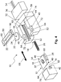
- Fig. 4 shows a further, third embodiment of a device 10, wherein additionally an electromagnet 36 is provided.
- the locking member 12 in the in Fig. 4 illustrated embodiment made of a magnetic metal or has at least one magnetic metal, so that the locking member 12 can be magnetically attracted by the electromagnet 36.
- the other components shown are in accordance with the in Fig. 3 illustrated embodiment formed and interconnected.
- a displacement of the Verrieglungsteils 12 done the different widths (in particular first width W 1 , second width W 2 ), in how far the locking member 12 protrudes from the receptacle 14, due to the position of the lower end of the guide element 20th in the heart curve 18, are variable by the electric motor.
- the electromagnet 36 has connecting lines 54, which serve to control or power supply of the electromagnet 36.
- Fig. 5 shows a further, fourth embodiment, wherein instead of a guide member 20 according to Fig. 3 , which consists of a disc or a plate 24 and a concentric pin 34, a pin-shaped guide member 20 is attached to a bracket 38 which abuts with its leg 78 on the rear wall 76 of the rear part 74. Tilting (for example, by a slight inclination of the guide member 20) is excluded due to the bracket 38 and the abutment of the leg 78 on the rear wall 76. Therefore, a guide plate 50 can be dispensed with, but with the in Fig. 5 As shown embodiment, a guide plate 50 may be additionally provided.
- the in the Fig. 1 to 5 shown embodiments have the advantage that they require relatively little space and specify a few components reliable and durable device 10 for moving a component 70 in the open and closed state.
- the slope 40 and the slope 42 may be formed according to the use of the device 10. Therefore, the slope 40 may have a much steeper or shallower angle (corresponding to the corresponding slope 42) than in FIGS Fig. 1 to 5 shown.
- an embodiment of a "push-push" mechanism with a device 10 (FIG. Fig. 1 to 5 ) has the advantage that no hooks are used, which must be introduced into a heart curve or engage behind a cutout or a recess. In the technical teaching disclosed here, only the locking member 12 is spent with relatively short strokes in the receptacle 14 or moved out of this.
- the bevels 52 of the side parts 72 are not relevant for the pivoting of the component 70. Therefore, the side parts 72 may also have a straight end. Furthermore, the receptacle 14, unlike in the Fig. 1 to 5 shown, instead of two side parts 72 and a rear part 74 integrally formed.
Landscapes
- Engineering & Computer Science (AREA)
- Mechanical Engineering (AREA)
- Physics & Mathematics (AREA)
- Thermal Sciences (AREA)
- Transportation (AREA)
- Casings For Electric Apparatus (AREA)
- Push-Button Switches (AREA)
- Toys (AREA)
Claims (12)
- Dispositif (10), présentant un mécanisme servant à amener un composant depuis un état ouvert dans un état fermé et inversement en appuyant sur le composant, dans lequel le dispositif présente un logement (14), un logement de composant (16) et une partie de verrouillage (12), laquelle est montée de manière à pouvoir coulisser dans le logement (14) et fait saillie hors du logement (14) sur une première largeur (W1) dans un état ouvert du composant et fait saillie hors du logement (14) d'une deuxième largeur (W2) dans un état fermé et est logée dans le logement de composant (16), dans lequel la deuxième largeur (W2) est plus grande que la première largeur (W1), dans lequel la partie de verrouillage (12) est logée dans le logement (14) à l'encontre de la force d'un dispositif à ressort et la partie de verrouillage (12) présente une cardioïde (18), dans laquelle un élément de guidage (20) est monté de manière à pouvoir coulisser, lequel peut être déplacé de manière transversale par rapport à la direction de coulissement (68) de la partie de verrouillage (12), et dans lequel la partie de verrouillage (12) présente au niveau du côté opposé au logement (14) un chanfrein (40) et le logement de composant (16) présente un chanfrein (42) correspondant, lesquels reposent l'un au niveau de l'autre dans l'état fermé du composant et peuvent être coulissés l'un par rapport à l'autre, dans lequel une première arête (82) du logement de composant (16) s'étend de manière décalée par rapport à une deuxième arête (84) du logement de composant (16).
- Dispositif (10) selon la revendication 1, présentant un guidage (22) s'étendant de manière transversale par rapport à la direction de coulissement (68) de la partie de verrouillage (12), dans lequel l'élément de guidage (20) peut être coulissé.
- Dispositif (10) selon la revendication 1 ou 2, dans lequel le dispositif à ressort présente au moins un ressort de pression.
- Dispositif (10) selon la revendication 1 ou 2, dans lequel le dispositif à ressort présente au moins deux aimants permanents, dans lequel un aimant permanent est disposé dans le logement (14) et l'autre aimant permanent, au niveau de la partie de verrouillage (12) et les aimants permanents sont orientés l'un par rapport à l'autre de telle sorte qu'ils se repoussent.
- Dispositif (10) selon l'une quelconque des revendications 1 à 3, présentant un électroaimant (36), dans lequel la partie de verrouillage (12) est constituée d'un métal magnétique et la partie de verrouillage (12) peut être déplacée par l'électroaimant (36) dans le logement (14) quand l'électroaimant (36) est activé.
- Dispositif (10) selon l'une quelconque des revendications 1 à 5, dans lequel l'élément de guidage (20) est une tige (92) et une première extrémité de la tige (92) est montée de manière à pouvoir coulisser dans la cardioïde (18) et la seconde extrémité (34) de la tige (92) est montée de manière à pouvoir coulisser dans le guidage (22) s'étendant de manière transversale.
- Dispositif (10) selon l'une quelconque des revendications 1 à 5, dans lequel l'élément de guidage est une bille.
- Dispositif (10) selon la revendication 6, dans lequel la tige présente entre la première extrémité et la seconde extrémité (34) une rondelle (24) entourant celle-ci, qui est montée de manière à pouvoir coulisser dans un espace dégagé entre le logement (14) et la partie de verrouillage (12).
- Dispositif (10) selon l'une quelconque des revendications 1 à 8, dans lequel la partie de verrouillage (12), l'élément de guidage (20) et/ou le logement (14) sont constitués d'une matière plastique et/ou de métal.
- Dispositif (10) selon l'une quelconque des revendications 1 à 9, dans lequel la partie de verrouillage (12) présente au niveau d'au moins un côté (60) des moyens de guidage (28), par l'intermédiaire desquels la partie de verrouillage (12) peut être coulissée au niveau d'au moins un moyen de guidage (30) correspondant du logement (14).
- Dispositif (10) selon l'une quelconque des revendications 1 à 10, dans lequel le chanfrein (40) de la partie de verrouillage (12) présente par rapport à un plan de coulissement un angle allant de 15° à 50°.
- Dispositif (10) selon l'une quelconque des revendications 1 à 5 et 9 à 11, dans lequel l'élément de guidage (20) est relié à un étrier (38), lequel peut être déplacé le long de et de manière transversale par rapport à une partie arrière (74) délimitant le logement (14).
Applications Claiming Priority (2)
| Application Number | Priority Date | Filing Date | Title |
|---|---|---|---|
| DE102013108794 | 2013-08-14 | ||
| PCT/EP2014/063160 WO2015022106A1 (fr) | 2013-08-14 | 2014-06-23 | Dispositif pourvu d'un mécanisme « push-push » |
Publications (2)
| Publication Number | Publication Date |
|---|---|
| EP3033464A1 EP3033464A1 (fr) | 2016-06-22 |
| EP3033464B1 true EP3033464B1 (fr) | 2019-01-02 |
Family
ID=51022846
Family Applications (1)
| Application Number | Title | Priority Date | Filing Date |
|---|---|---|---|
| EP14733594.7A Active EP3033464B1 (fr) | 2013-08-14 | 2014-06-23 | Dispositif avec mécanisme push-push |
Country Status (3)
| Country | Link |
|---|---|
| EP (1) | EP3033464B1 (fr) |
| CN (1) | CN105556046B (fr) |
| WO (1) | WO2015022106A1 (fr) |
Cited By (1)
| Publication number | Priority date | Publication date | Assignee | Title |
|---|---|---|---|---|
| DE102023105935A1 (de) | 2023-03-09 | 2024-09-12 | Bayerische Motoren Werke Aktiengesellschaft | Anordnung eines Außengriffs an einem Flügelelement, insbesondere einer Fahrzeugtür, für ein Fahrzeug sowie Fahrzeug, insbesondere Kraftfahrzeug |
Families Citing this family (5)
| Publication number | Priority date | Publication date | Assignee | Title |
|---|---|---|---|---|
| CN106049937B (zh) * | 2016-07-25 | 2019-01-29 | 曾庆义 | 带安全锁的无避让多层停车装置 |
| DE102017104476B4 (de) | 2017-03-03 | 2023-06-15 | Lisa Dräxlmaier GmbH | Interieuranordnung für ein kraftfahrzeug |
| CN109209084B (zh) * | 2017-07-06 | 2024-01-16 | 杭州神林电子有限公司 | 一种家用电器用的门盖锁止装置 |
| DE102018120620A1 (de) * | 2018-08-23 | 2020-02-27 | Emka Beschlagteile Gmbh & Co. Kg | Verschlussvorrichtung für eine Tür |
| CN115956155A (zh) * | 2020-08-19 | 2023-04-11 | 韦伯两合公司塑料技术与成形 | 用于尤其是机动车的、可相对于壳体部件在关闭位态和打开位态之间操纵的容器或盖的锁定装置 |
Family Cites Families (8)
| Publication number | Priority date | Publication date | Assignee | Title |
|---|---|---|---|---|
| FR1588802A (fr) * | 1968-04-26 | 1970-03-16 | ||
| DE10211124A1 (de) * | 2002-03-14 | 2003-09-25 | Hella Kg Hueck & Co | Schminkspiegelleuchte zum Einbau in ein Fahrzeugdach |
| KR100633137B1 (ko) * | 2005-08-26 | 2006-10-12 | 현대모비스 주식회사 | 트레이 래칭장치 |
| JP4906706B2 (ja) * | 2007-12-26 | 2012-03-28 | 株式会社ニフコ | 安全装置及び開閉機構 |
| EP2343426B1 (fr) * | 2008-10-29 | 2017-06-07 | Nifco INC. | Dispositif de verrou |
| JP5295074B2 (ja) * | 2009-11-02 | 2013-09-18 | 株式会社ニフコ | ロック装置及びそれを用いた扉 |
| JP5789438B2 (ja) * | 2011-07-13 | 2015-10-07 | 株式会社ニフコ | ラッチ装置 |
| CN103703203B (zh) * | 2011-08-09 | 2016-08-17 | 伊利诺斯工具制品有限公司 | 推动/推动式闩锁 |
-
2014
- 2014-06-23 EP EP14733594.7A patent/EP3033464B1/fr active Active
- 2014-06-23 CN CN201480044125.2A patent/CN105556046B/zh active Active
- 2014-06-23 WO PCT/EP2014/063160 patent/WO2015022106A1/fr not_active Ceased
Non-Patent Citations (1)
| Title |
|---|
| None * |
Cited By (1)
| Publication number | Priority date | Publication date | Assignee | Title |
|---|---|---|---|---|
| DE102023105935A1 (de) | 2023-03-09 | 2024-09-12 | Bayerische Motoren Werke Aktiengesellschaft | Anordnung eines Außengriffs an einem Flügelelement, insbesondere einer Fahrzeugtür, für ein Fahrzeug sowie Fahrzeug, insbesondere Kraftfahrzeug |
Also Published As
| Publication number | Publication date |
|---|---|
| CN105556046B (zh) | 2017-05-10 |
| CN105556046A (zh) | 2016-05-04 |
| WO2015022106A1 (fr) | 2015-02-19 |
| EP3033464A1 (fr) | 2016-06-22 |
Similar Documents
| Publication | Publication Date | Title |
|---|---|---|
| EP3870786B1 (fr) | Serrure conçue pour un véhicule automobile, en particulier serrure de véhicule automobile à actionnement électrique | |
| EP3033464B1 (fr) | Dispositif avec mécanisme push-push | |
| DE112009001288T5 (de) | Fahrzeugschloss | |
| DE102015111529B4 (de) | Schloss | |
| EP3517714A1 (fr) | Gâchette et dispositif de sécurité de faible encombrement | |
| EP3675691B1 (fr) | Dispositif d'insertion permettant d'insérer une partie mobile d'un meuble ou d'un appareil ménager dans une position finale | |
| EP2843169B1 (fr) | Porte coulissante avec système de support | |
| EP2840214A1 (fr) | Dispositif ferme-porte | |
| DE102017208721A1 (de) | Gegenkasten für ein Paniktürschloss | |
| WO2005118989A1 (fr) | Systeme de verrouillage | |
| EP1350655B1 (fr) | Mécanisme de verrouillage pour un bouchon de réservoir de carburant | |
| DE202016101097U1 (de) | Verriegelungseinrichtung und dazugehörige Schiebetüranlage | |
| EP2078812A2 (fr) | Elément de recouvrement pour un rail de guidage | |
| DE102013212514B4 (de) | Türanlage mit einer Verriegelungseinrichtung zur Verriegelung eines Türflügels | |
| DE202016007457U1 (de) | Drehriegelschloss | |
| DE202011105510U1 (de) | Türöffner mit Sperr-Riegel | |
| DE102010018867A1 (de) | Fahrzeugdach und Verfahren zum Öffnen und Schließen eines Fahrzeugdachs | |
| DE102012007023A1 (de) | Schlossvorrichtung zum Verhindern einer Kollision | |
| DE102008061293A1 (de) | Verriegelungsanordnung für eine elektronische Zentralverriegelung | |
| DE3425090C1 (de) | Verriegelungsvorrichtung mit wenigstens einem Riegel oder dgl. und mit einer Sperre fuer diesen Riegel | |
| DE102015211295A1 (de) | Vorrichtung zum Sichern von Ladegut in einem Laderaum eines Kraftfahrzeugs | |
| DE112007002208T5 (de) | Verriegelungsvorrichtung | |
| EP4042846A1 (fr) | Armoire de distribution comprenant un élément de fermeture précontraint dans une position d'ouverture | |
| DE102015100381A1 (de) | Schwenkhebelverschluss mit einer Sperreinrichtung für das Verriegelungsteil | |
| EP4155491B1 (fr) | Dispositif de fermeture, en particulier pour caravane ou camping-car |
Legal Events
| Date | Code | Title | Description |
|---|---|---|---|
| PUAI | Public reference made under article 153(3) epc to a published international application that has entered the european phase |
Free format text: ORIGINAL CODE: 0009012 |
|
| 17P | Request for examination filed |
Effective date: 20160203 |
|
| AK | Designated contracting states |
Kind code of ref document: A1 Designated state(s): AL AT BE BG CH CY CZ DE DK EE ES FI FR GB GR HR HU IE IS IT LI LT LU LV MC MK MT NL NO PL PT RO RS SE SI SK SM TR |
|
| AX | Request for extension of the european patent |
Extension state: BA ME |
|
| DAX | Request for extension of the european patent (deleted) | ||
| GRAP | Despatch of communication of intention to grant a patent |
Free format text: ORIGINAL CODE: EPIDOSNIGR1 |
|
| STAA | Information on the status of an ep patent application or granted ep patent |
Free format text: STATUS: GRANT OF PATENT IS INTENDED |
|
| INTG | Intention to grant announced |
Effective date: 20180831 |
|
| GRAS | Grant fee paid |
Free format text: ORIGINAL CODE: EPIDOSNIGR3 |
|
| GRAA | (expected) grant |
Free format text: ORIGINAL CODE: 0009210 |
|
| STAA | Information on the status of an ep patent application or granted ep patent |
Free format text: STATUS: THE PATENT HAS BEEN GRANTED |
|
| AK | Designated contracting states |
Kind code of ref document: B1 Designated state(s): AL AT BE BG CH CY CZ DE DK EE ES FI FR GB GR HR HU IE IS IT LI LT LU LV MC MK MT NL NO PL PT RO RS SE SI SK SM TR |
|
| REG | Reference to a national code |
Ref country code: GB Ref legal event code: FG4D Free format text: NOT ENGLISH |
|
| REG | Reference to a national code |
Ref country code: CH Ref legal event code: EP Ref country code: AT Ref legal event code: REF Ref document number: 1084584 Country of ref document: AT Kind code of ref document: T Effective date: 20190115 |
|
| REG | Reference to a national code |
Ref country code: IE Ref legal event code: FG4D Free format text: LANGUAGE OF EP DOCUMENT: GERMAN |
|
| REG | Reference to a national code |
Ref country code: DE Ref legal event code: R096 Ref document number: 502014010536 Country of ref document: DE |
|
| REG | Reference to a national code |
Ref country code: SE Ref legal event code: TRGR |
|
| REG | Reference to a national code |
Ref country code: NL Ref legal event code: MP Effective date: 20190102 |
|
| REG | Reference to a national code |
Ref country code: LT Ref legal event code: MG4D |
|
| PG25 | Lapsed in a contracting state [announced via postgrant information from national office to epo] |
Ref country code: NL Free format text: LAPSE BECAUSE OF FAILURE TO SUBMIT A TRANSLATION OF THE DESCRIPTION OR TO PAY THE FEE WITHIN THE PRESCRIBED TIME-LIMIT Effective date: 20190102 |
|
| PG25 | Lapsed in a contracting state [announced via postgrant information from national office to epo] |
Ref country code: FI Free format text: LAPSE BECAUSE OF FAILURE TO SUBMIT A TRANSLATION OF THE DESCRIPTION OR TO PAY THE FEE WITHIN THE PRESCRIBED TIME-LIMIT Effective date: 20190102 Ref country code: LT Free format text: LAPSE BECAUSE OF FAILURE TO SUBMIT A TRANSLATION OF THE DESCRIPTION OR TO PAY THE FEE WITHIN THE PRESCRIBED TIME-LIMIT Effective date: 20190102 Ref country code: PT Free format text: LAPSE BECAUSE OF FAILURE TO SUBMIT A TRANSLATION OF THE DESCRIPTION OR TO PAY THE FEE WITHIN THE PRESCRIBED TIME-LIMIT Effective date: 20190502 Ref country code: NO Free format text: LAPSE BECAUSE OF FAILURE TO SUBMIT A TRANSLATION OF THE DESCRIPTION OR TO PAY THE FEE WITHIN THE PRESCRIBED TIME-LIMIT Effective date: 20190402 Ref country code: ES Free format text: LAPSE BECAUSE OF FAILURE TO SUBMIT A TRANSLATION OF THE DESCRIPTION OR TO PAY THE FEE WITHIN THE PRESCRIBED TIME-LIMIT Effective date: 20190102 Ref country code: PL Free format text: LAPSE BECAUSE OF FAILURE TO SUBMIT A TRANSLATION OF THE DESCRIPTION OR TO PAY THE FEE WITHIN THE PRESCRIBED TIME-LIMIT Effective date: 20190102 |
|
| PG25 | Lapsed in a contracting state [announced via postgrant information from national office to epo] |
Ref country code: RS Free format text: LAPSE BECAUSE OF FAILURE TO SUBMIT A TRANSLATION OF THE DESCRIPTION OR TO PAY THE FEE WITHIN THE PRESCRIBED TIME-LIMIT Effective date: 20190102 Ref country code: LV Free format text: LAPSE BECAUSE OF FAILURE TO SUBMIT A TRANSLATION OF THE DESCRIPTION OR TO PAY THE FEE WITHIN THE PRESCRIBED TIME-LIMIT Effective date: 20190102 Ref country code: GR Free format text: LAPSE BECAUSE OF FAILURE TO SUBMIT A TRANSLATION OF THE DESCRIPTION OR TO PAY THE FEE WITHIN THE PRESCRIBED TIME-LIMIT Effective date: 20190403 Ref country code: HR Free format text: LAPSE BECAUSE OF FAILURE TO SUBMIT A TRANSLATION OF THE DESCRIPTION OR TO PAY THE FEE WITHIN THE PRESCRIBED TIME-LIMIT Effective date: 20190102 Ref country code: IS Free format text: LAPSE BECAUSE OF FAILURE TO SUBMIT A TRANSLATION OF THE DESCRIPTION OR TO PAY THE FEE WITHIN THE PRESCRIBED TIME-LIMIT Effective date: 20190502 Ref country code: BG Free format text: LAPSE BECAUSE OF FAILURE TO SUBMIT A TRANSLATION OF THE DESCRIPTION OR TO PAY THE FEE WITHIN THE PRESCRIBED TIME-LIMIT Effective date: 20190402 |
|
| REG | Reference to a national code |
Ref country code: DE Ref legal event code: R097 Ref document number: 502014010536 Country of ref document: DE |
|
| PG25 | Lapsed in a contracting state [announced via postgrant information from national office to epo] |
Ref country code: EE Free format text: LAPSE BECAUSE OF FAILURE TO SUBMIT A TRANSLATION OF THE DESCRIPTION OR TO PAY THE FEE WITHIN THE PRESCRIBED TIME-LIMIT Effective date: 20190102 Ref country code: DK Free format text: LAPSE BECAUSE OF FAILURE TO SUBMIT A TRANSLATION OF THE DESCRIPTION OR TO PAY THE FEE WITHIN THE PRESCRIBED TIME-LIMIT Effective date: 20190102 Ref country code: CZ Free format text: LAPSE BECAUSE OF FAILURE TO SUBMIT A TRANSLATION OF THE DESCRIPTION OR TO PAY THE FEE WITHIN THE PRESCRIBED TIME-LIMIT Effective date: 20190102 Ref country code: RO Free format text: LAPSE BECAUSE OF FAILURE TO SUBMIT A TRANSLATION OF THE DESCRIPTION OR TO PAY THE FEE WITHIN THE PRESCRIBED TIME-LIMIT Effective date: 20190102 Ref country code: IT Free format text: LAPSE BECAUSE OF FAILURE TO SUBMIT A TRANSLATION OF THE DESCRIPTION OR TO PAY THE FEE WITHIN THE PRESCRIBED TIME-LIMIT Effective date: 20190102 Ref country code: SK Free format text: LAPSE BECAUSE OF FAILURE TO SUBMIT A TRANSLATION OF THE DESCRIPTION OR TO PAY THE FEE WITHIN THE PRESCRIBED TIME-LIMIT Effective date: 20190102 Ref country code: AL Free format text: LAPSE BECAUSE OF FAILURE TO SUBMIT A TRANSLATION OF THE DESCRIPTION OR TO PAY THE FEE WITHIN THE PRESCRIBED TIME-LIMIT Effective date: 20190102 |
|
| PLBE | No opposition filed within time limit |
Free format text: ORIGINAL CODE: 0009261 |
|
| STAA | Information on the status of an ep patent application or granted ep patent |
Free format text: STATUS: NO OPPOSITION FILED WITHIN TIME LIMIT |
|
| PG25 | Lapsed in a contracting state [announced via postgrant information from national office to epo] |
Ref country code: SM Free format text: LAPSE BECAUSE OF FAILURE TO SUBMIT A TRANSLATION OF THE DESCRIPTION OR TO PAY THE FEE WITHIN THE PRESCRIBED TIME-LIMIT Effective date: 20190102 |
|
| 26N | No opposition filed |
Effective date: 20191003 |
|
| PG25 | Lapsed in a contracting state [announced via postgrant information from national office to epo] |
Ref country code: MC Free format text: LAPSE BECAUSE OF FAILURE TO SUBMIT A TRANSLATION OF THE DESCRIPTION OR TO PAY THE FEE WITHIN THE PRESCRIBED TIME-LIMIT Effective date: 20190102 |
|
| REG | Reference to a national code |
Ref country code: CH Ref legal event code: PL |
|
| PG25 | Lapsed in a contracting state [announced via postgrant information from national office to epo] |
Ref country code: SI Free format text: LAPSE BECAUSE OF FAILURE TO SUBMIT A TRANSLATION OF THE DESCRIPTION OR TO PAY THE FEE WITHIN THE PRESCRIBED TIME-LIMIT Effective date: 20190102 |
|
| REG | Reference to a national code |
Ref country code: BE Ref legal event code: MM Effective date: 20190630 |
|
| PG25 | Lapsed in a contracting state [announced via postgrant information from national office to epo] |
Ref country code: TR Free format text: LAPSE BECAUSE OF FAILURE TO SUBMIT A TRANSLATION OF THE DESCRIPTION OR TO PAY THE FEE WITHIN THE PRESCRIBED TIME-LIMIT Effective date: 20190102 |
|
| PG25 | Lapsed in a contracting state [announced via postgrant information from national office to epo] |
Ref country code: IE Free format text: LAPSE BECAUSE OF NON-PAYMENT OF DUE FEES Effective date: 20190623 |
|
| PG25 | Lapsed in a contracting state [announced via postgrant information from national office to epo] |
Ref country code: CH Free format text: LAPSE BECAUSE OF NON-PAYMENT OF DUE FEES Effective date: 20190630 Ref country code: BE Free format text: LAPSE BECAUSE OF NON-PAYMENT OF DUE FEES Effective date: 20190630 Ref country code: LI Free format text: LAPSE BECAUSE OF NON-PAYMENT OF DUE FEES Effective date: 20190630 Ref country code: LU Free format text: LAPSE BECAUSE OF NON-PAYMENT OF DUE FEES Effective date: 20190623 |
|
| REG | Reference to a national code |
Ref country code: AT Ref legal event code: MM01 Ref document number: 1084584 Country of ref document: AT Kind code of ref document: T Effective date: 20190623 |
|
| PG25 | Lapsed in a contracting state [announced via postgrant information from national office to epo] |
Ref country code: AT Free format text: LAPSE BECAUSE OF NON-PAYMENT OF DUE FEES Effective date: 20190623 |
|
| PG25 | Lapsed in a contracting state [announced via postgrant information from national office to epo] |
Ref country code: CY Free format text: LAPSE BECAUSE OF FAILURE TO SUBMIT A TRANSLATION OF THE DESCRIPTION OR TO PAY THE FEE WITHIN THE PRESCRIBED TIME-LIMIT Effective date: 20190102 |
|
| PG25 | Lapsed in a contracting state [announced via postgrant information from national office to epo] |
Ref country code: MT Free format text: LAPSE BECAUSE OF FAILURE TO SUBMIT A TRANSLATION OF THE DESCRIPTION OR TO PAY THE FEE WITHIN THE PRESCRIBED TIME-LIMIT Effective date: 20190102 Ref country code: HU Free format text: LAPSE BECAUSE OF FAILURE TO SUBMIT A TRANSLATION OF THE DESCRIPTION OR TO PAY THE FEE WITHIN THE PRESCRIBED TIME-LIMIT; INVALID AB INITIO Effective date: 20140623 |
|
| PG25 | Lapsed in a contracting state [announced via postgrant information from national office to epo] |
Ref country code: MK Free format text: LAPSE BECAUSE OF FAILURE TO SUBMIT A TRANSLATION OF THE DESCRIPTION OR TO PAY THE FEE WITHIN THE PRESCRIBED TIME-LIMIT Effective date: 20190102 |
|
| P01 | Opt-out of the competence of the unified patent court (upc) registered |
Effective date: 20230525 |
|
| PGFP | Annual fee paid to national office [announced via postgrant information from national office to epo] |
Ref country code: SE Payment date: 20240626 Year of fee payment: 11 |
|
| REG | Reference to a national code |
Ref country code: DE Ref legal event code: R081 Ref document number: 502014010536 Country of ref document: DE Owner name: MOTHERSON DRSC DEUTSCHLAND GMBH, DE Free format text: FORMER OWNER: DR. SCHNEIDER KUNSTSTOFFWERKE GMBH, 96317 KRONACH, DE |
|
| PGFP | Annual fee paid to national office [announced via postgrant information from national office to epo] |
Ref country code: DE Payment date: 20250226 Year of fee payment: 12 |
|
| PGFP | Annual fee paid to national office [announced via postgrant information from national office to epo] |
Ref country code: GB Payment date: 20250620 Year of fee payment: 12 |
|
| PGFP | Annual fee paid to national office [announced via postgrant information from national office to epo] |
Ref country code: FR Payment date: 20250626 Year of fee payment: 12 |
|
| REG | Reference to a national code |
Ref country code: GB Ref legal event code: 732E Free format text: REGISTERED BETWEEN 20250724 AND 20250730 |
|
| REG | Reference to a national code |
Ref country code: SE Ref legal event code: EUG |