EP3033525B1 - Procédé et unité de pompage de produits inflammables susceptibles de former une atmosphere explosive - Google Patents
Procédé et unité de pompage de produits inflammables susceptibles de former une atmosphere explosive Download PDFInfo
- Publication number
- EP3033525B1 EP3033525B1 EP14749935.4A EP14749935A EP3033525B1 EP 3033525 B1 EP3033525 B1 EP 3033525B1 EP 14749935 A EP14749935 A EP 14749935A EP 3033525 B1 EP3033525 B1 EP 3033525B1
- Authority
- EP
- European Patent Office
- Prior art keywords
- separator
- pumping
- products
- pump
- unit according
- Prior art date
- Legal status (The legal status is an assumption and is not a legal conclusion. Google has not performed a legal analysis and makes no representation as to the accuracy of the status listed.)
- Active
Links
Images


Classifications
-
- F—MECHANICAL ENGINEERING; LIGHTING; HEATING; WEAPONS; BLASTING
- F04—POSITIVE - DISPLACEMENT MACHINES FOR LIQUIDS; PUMPS FOR LIQUIDS OR ELASTIC FLUIDS
- F04B—POSITIVE-DISPLACEMENT MACHINES FOR LIQUIDS; PUMPS
- F04B15/00—Pumps adapted to handle specific fluids, e.g. by selection of specific materials for pumps or pump parts
- F04B15/02—Pumps adapted to handle specific fluids, e.g. by selection of specific materials for pumps or pump parts the fluids being viscous or non-homogeneous
-
- B—PERFORMING OPERATIONS; TRANSPORTING
- B01—PHYSICAL OR CHEMICAL PROCESSES OR APPARATUS IN GENERAL
- B01D—SEPARATION
- B01D19/00—Degasification of liquids
- B01D19/0042—Degasification of liquids modifying the liquid flow
- B01D19/0052—Degasification of liquids modifying the liquid flow in rotating vessels, vessels containing movable parts or in which centrifugal movement is caused
- B01D19/0057—Degasification of liquids modifying the liquid flow in rotating vessels, vessels containing movable parts or in which centrifugal movement is caused the centrifugal movement being caused by a vortex, e.g. using a cyclone, or by a tangential inlet
-
- B—PERFORMING OPERATIONS; TRANSPORTING
- B01—PHYSICAL OR CHEMICAL PROCESSES OR APPARATUS IN GENERAL
- B01D—SEPARATION
- B01D45/00—Separating dispersed particles from gases or vapours by gravity, inertia, or centrifugal forces
- B01D45/12—Separating dispersed particles from gases or vapours by gravity, inertia, or centrifugal forces by centrifugal forces
-
- F—MECHANICAL ENGINEERING; LIGHTING; HEATING; WEAPONS; BLASTING
- F04—POSITIVE - DISPLACEMENT MACHINES FOR LIQUIDS; PUMPS FOR LIQUIDS OR ELASTIC FLUIDS
- F04B—POSITIVE-DISPLACEMENT MACHINES FOR LIQUIDS; PUMPS
- F04B23/00—Pumping installations or systems
- F04B23/02—Pumping installations or systems having reservoirs
-
- F—MECHANICAL ENGINEERING; LIGHTING; HEATING; WEAPONS; BLASTING
- F04—POSITIVE - DISPLACEMENT MACHINES FOR LIQUIDS; PUMPS FOR LIQUIDS OR ELASTIC FLUIDS
- F04B—POSITIVE-DISPLACEMENT MACHINES FOR LIQUIDS; PUMPS
- F04B53/00—Component parts, details or accessories not provided for in, or of interest apart from, groups F04B1/00 - F04B23/00 or F04B39/00 - F04B47/00
- F04B53/20—Filtering
Definitions
- the invention relates to a method and a unit for pumping flammable, liquid or pasty products.
- the invention relates to a method and a unit for pumping hydrocarbons, acids, bases, sewage sludge, biological sludge, primary sludge and in general all similar flammable products capable of producing an explosive atmosphere (better known by the acronym ATEX).
- ATEX flammable, liquid or pasty products.
- the invention relates in particular to mobile pumping units such as sewer cleaners intended for emptying ATEX sludge storage areas.
- flammable product denote indifferently hydrocarbons, acids, bases, sewage sludge, biological sludge, primary sludge and in general all similar flammable products capable of forming an explosive atmosphere. These flammable products can also be toxic.
- An "explosive atmosphere” is a mixture with air, under atmospheric conditions, of flammable substances in the form of gases, vapors, mists or dust, in which, after ignition, combustion spreads to the whole unburned mixture .
- an "explosive atmosphere” is one that can become explosive due to specific local conditions.
- Vacuum pumping consists in using a vacuum pump to empty the tank containing the products to be pumped, without introducing air.
- a storage enclosure is arranged between the pump and a suction pipe permanently submerged in the product to be pumped.
- This technique has the advantages of allowing the vacuum pump to stop operating during the pumping operation, while maintaining a suction capacity as long as the differential with respect to atmospheric pressure exists. In addition, it allows the installation of the pump at great distances from the product to be pumped due to the suction force. It also makes it possible to avoid contact of the product with the pump with the exception of vapors or gases and to limit the quantity of pollutants released.
- this pumping technique has in particular the disadvantages of favoring the boiling of volatile products and the desorption of gases, of increasing the risks of explosion and the emission of harmful gases such as volatile organic compounds.
- Air pumping consists in using a vacuum pump to empty the tank containing the products to be pumped, but with the introduction of air.
- the addition of air can be voluntary to promote the transport of the product and increase the pumping efficiency or involuntary when at the end of pumping, the hose is no longer sufficiently submerged in the product.
- This technique requires a permanent operation of the pump and has the advantages of being able to install the pump at very great distances from the product to be pumped due to the suction force, of being able to pump liquid products containing solid foreign bodies (impossible with a positive displacement pump) and to be able to pump products from the ground. It also avoids contact of the product with the pump except for vapors or gases.
- Transfer pumping consists in using a positive displacement pump which directly sucks the products.
- This technique has the advantages of being able to pump very volatile products, of limiting the discharge of pollutants and of pumping viscous and pasty products.
- this technique if it is the one which presents the least risk, is abandoned today because it is not compatible with high pumping rates and does not allow the tanks to be completely emptied.
- the limited suction force of this type of pump makes it necessary to position it near the drain pan.
- the invention aims to overcome at least some of the drawbacks of known pumping devices and methods.
- the invention aims to provide, in at least one embodiment of the invention, a pumping device and method which make it possible to limit the dangerousness and the toxicity of a pumping operation for flammable products capable of forming an explosive atmosphere while retaining high pumping rates.
- the invention also aims to provide, in at least one embodiment, a pumping device and method which make it possible to limit the time of exposure to vacuum of the pumped products so as to limit the phenomena of desorption of the gases dissolved in the products.
- the invention also aims to provide, in at least one embodiment of the invention, a pumping device and method which make it possible to reduce the quantity of air admitted into the pumping circuit.
- the invention also aims to provide, in at least one embodiment of the invention, a pumping device and method which make it possible to reduce the surface exposed to vacuum.
- the invention also aims to provide, in at least one embodiment of the invention, a pumping device and method which make it possible to limit the discharges of harmful gases.
- the invention also aims to provide, in at least one embodiment of the invention, a pumping device and method which make it possible to confine the dangerous zone to the pumping zone.
- a unit according to the invention therefore makes it possible to limit the phenomenon of desorption of the pumped products by the implementation of two circuits, a short vacuum suction circuit and a discharge pressure circuit for non-gaseous products.
- the product separator is directly arranged in the pumping zone and the vacuum suction circuit aims only at the suction of the products from the pumping zone into the cyclonic tank of the separator.
- the terms “pumping area” designate the tank which contains the products to be pumped and a certain area which surrounds this tank. This area is defined by the various laws relating to pumping of ATEX product. In other words, it is the geographic area that contains and surrounds the products to be pumped. It is therefore not limited only to the tank which contains the products to be pumped but also to its immediate vicinity.
- the discharge of products from the separator to the storage area is obtained by the implementation of a pressure circuit comprising a positive displacement pump.
- This product transfer is therefore not obtained by using a vacuum circuit, which limits the time of exposure of the products to vacuum, and therefore the desorption of gases, and therefore the toxicological and explosion risks.
- the storage enclosure for flammable products is not placed under vacuum, which very strongly limits desorption over the total duration of the pumping operation and therefore the emissions of harmful and explosive gases. The risks of explosion are greatly reduced.
- a pumping unit according to the invention therefore makes it possible to greatly limit the dangerousness of the pumping operation while maintaining a good pumping rate and an ability to ensure the total emptying of the tank to be cleaned.
- the vacuum circuit being short, the quantity of air, which acts as oxidizer, admitted into the vacuum circuit to ensure the transfer of flammable products from the pumping zone to the storage enclosure, is scaled down. This also helps to limit the danger of the pumping operation.
- said means for placing said separator under vacuum comprise a vacuum pump arranged outside said pumping zone and the storage enclosure and connected to said suction orifice of said separator .
- the vacuum necessary to ensure the transfer of flammable products from the pumping zone to the tank of the separator is obtained by the use of a vacuum pump which is installed outside from both the pumping area and the storage enclosure.
- the vacuum pump of the hydro-curer truck can act as the vacuum pump of the invention.
- This vacuum pump is arranged so that the storage enclosure is not on the vacuum circuit upstream of the vacuum pump so that the enclosure can be at atmospheric pressure.
- said gas rejection circuit comprises a pipe for rejecting the gases produced by said separator and connected to said suction port of said separator, said vacuum pump being arranged on this pipe, so that this pipe contributes both to the vacuuming of said cyclonic tank and to the transfer of the gases produced by the separator to a marked rejection zone.
- the gas rejection circuit ensures the rejection of the gases produced by said unit to at least one marked rejection zone.
- the gas rejection circuit also comprises a safety valve formed in the storage enclosure and maintained in the open position to protect the enclosure against risks of overpressure by keeping it at atmospheric pressure.
- the gas rejection circuit comprises a pipe for rejection of the gases resulting from the desorption of the products in the storage enclosure arranged between the safety valve and a marked rejection zone.
- said means for placing said product separator under vacuum comprise a hydro-injector mounted on said suction port of said separator and supplied with high-pressure water from a water reserve.
- the vacuum is created in the cyclonic tank of the separator by the use of a hydro-injector supplied with high-pressure water from a water reserve.
- This hydro-injector supplied with high-pressure water, creates a Venturi effect, leading to the suction of products from the pumping zone to the cyclonic tank of the separator.
- a pumping unit according to this second variant is particularly advantageous because it does not require the use of a vacuum pump. Only a high-pressure water pump is required to pump flammable products.
- the danger zone is exclusively confined to the pumping zone already classified as an ATEX zone.
- the high-pressure water reserve of the truck can act as a water reserve for the hydro injector of the unit according to the invention and the high-pressure pump of the truck makes it possible to supply the hydro-injector with high-pressure water.
- a pumping unit comprises a hydro-cyclone suitable for degassing the high-pressure water coming from said hydro-injector.
- the hydro-cyclone makes it possible to separate the gases from the water coming from the hydro-injector.
- the flammable products are separated into a pasty / liquid phase and a gaseous phase at the flammable product separator, the gaseous phase then being absorbed by the high-pressure water of the hydro -injector.
- the water is then itself separated into a liquid phase and a gas phase at the level of the hydro-cyclone.
- This gas phase obtained by the hydro-cyclone is substantially identical to the gas phase coming from the separator and transported by high pressure water.
- a pumping unit comprises a volumetric pump for discharging degassed water to said water reserve.
- the unit comprises two positive displacement pumps, a pump for discharging the pasty / liquid phase of the products pumped at the outlet of the separator, and a pump for discharging the water degassed by the hydro-cyclone.
- said gas rejection circuit comprises a pipe for rejecting gases produced by said hydro-cyclone towards a marked rejection zone.
- the gas rejection circuit ensures the rejection of the gases produced by said unit to at least one marked rejection zone.
- the gas rejection circuit also comprises a safety valve formed in the storage enclosure and maintained in the open position to protect the enclosure against risks of overpressure by keeping it at atmospheric pressure.
- the gas rejection circuit comprises a pipe for rejection of the gases resulting from the desorption of the products in the storage enclosure arranged between the safety valve and a marked rejection zone.
- the gas discharge pipe produced by said hydro-cyclone has an outlet located on the marked discharge zone of the tank to be drained.
- the storage enclosure only emits an insignificant release of gas to the atmosphere.
- said storage enclosure is arranged at a distance of 50 to 100 meters from the pumping zone.
- a pumping unit according to the invention makes it possible to pump a flammable product over a long distance, of the order of 50 to 100 meters.
- the operator can therefore install the pumping unit, in particular the separator in the pumping area and join the hydro-curer truck which carries the storage enclosure . Consequently, the equipment located more than 50 meters from the danger zone no longer constitutes a new ATEX zone.
- the risk of accident is reduced - notably by a reduction in the distance of the vacuum circuit - and the safety provided to operators is improved by allowing them to control pumping at a long distance from the area pumping.
- said volumetric product delivery pump is a pneumatic pump actuated by compressed air.
- this positive displacement pump can be a pump actuated by hydraulic energy.
- a pumping unit according to the invention is carried by a hydro-curator combination.
- the method according to the invention is advantageously implemented by a pumping unit according to the invention and a pumping unit according to the invention advantageously implements a method according to the invention.
- the step of placing the separator under vacuum consists in connecting a vacuum pump to the separator, said pump being arranged outside the pumping zone and the storage enclosure.
- the step of placing said separator under vacuum consists in injecting high-pressure water into a hydro-injector mounted on said separator from a water reserve.
- a method according to this second variant comprises a step of supplying a hydro-cyclone with degassed high-pressure water and a step of returning this water to a water reserve.
- the invention also relates to a pumping unit and a pumping method characterized in combination by all or some of the characteristics mentioned above or below.
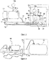
- This pumping unit includes a pump 10 to vacuum intended to create a vacuum in a storage enclosure 11.
- This storage enclosure 11 is connected to a pumping area 73 by means of a pipe 12 for transferring the pumped products.
- the suction of flammable products is therefore done by the vacuuming of the storage enclosure 11 and the gases resulting from the desorption of the products are discharged to a zone 14 of marked rejection arranged at the end of a pipe 15 of gas rejection, itself arranged between this rejection zone 14 and the storage enclosure 11.
- This rejection zone 14 of gases harmful to the open air is substantial for a pumping unit of the prior art.
- the unit for pumping flammable products capable of forming an explosive atmosphere from a pumping zone 73 to a storage enclosure 11 comprises a separator 20 for products in a liquid / pasty phase and a gaseous phase.
- the pumping zone 73 comprises an assembly 13 which is described below and a tank of products to be pumped, not shown on the figures 2 and 3 for clarity.
- the product separator 20 comprises a cyclonic tank 21, a product inlet mouth 22, an outlet 23 for discharging non-gaseous products and a suction orifice 24.
- the figure 5 presents an embodiment of this product separator 20.
- the cyclonic tank 21 is of reduced capacity, of the order of 200 to 300 liters.
- This makes it possible to have a separator of reduced dimensions and of weight compatible with an operation operation by an operator. In addition, it helps to allow a good suction flow while limiting the risk of explosion.
- the separator is for example adapted to be mounted on a pallet (better known under the English name skid ) .
- the separator according to the embodiment of the figure 5 comprises a base 25 forming a handling pallet. This base 25 has openings 26, 27 adapted to allow the passage of the forks of a forklift. Such a separator is therefore easily maneuverable by an operator and can be arranged directly in the pumping area, near the tank containing the products to be pumped.
- the pumping unit according to the invention further comprises a volumetric pump 30 for discharging non-gaseous products separated by the separator 20, towards the enclosure 11 for storage.
- This volumetric pump 30 is connected to the outlet 23 for discharging the products from the separator 20.
- a pipe 31 connects the volumetric pump 30 to the storage enclosure 11.
- This pipe is for example a resistant flexible hose.
- this positive displacement pump is a pneumatic or hydraulic drive pump.
- a source 40 of compressed air or pressurized hydraulic oil supplies the volumetric pump 30 via a pipe 41.
- the pumping unit according to the invention further comprises means for evacuating the cyclonic tank 21 of the separator 20 of products suitable for ensuring the suction of the products from the pumping zone 73 towards the tank 21 of the separator 20.
- the means for placing the separator 20 under vacuum comprise a vacuum pump 35.
- This pump 35 is connected to the suction port 24 of the separator 20.
- This vacuum pump 35 can be of any known type. It is arranged outside the pumping zone 73 and the storage enclosure 11. In the case where the pumping unit is mounted on a hydro-curator truck, the vacuum pump of the truck can act as a vacuum pump of the pumping unit.
- a line 36a connects the suction port 24 to the vacuum pump 35 and a line 36b connects the vacuum pump 35 to a marked rejection zone 14a.
- the vacuum pump 35 when the vacuum pump 35 is activated, the vacuum is created inside the cyclonic tank 21, which generates a phenomenon of suction of the products from the pumping zone into the cyclonic tank 21 via 'A pipe 32 arranged between the mouth 22 for entering the products into the separator 20 and the pumping zone 73.
- the products are separated by the separator 20 into a liquid / pasty phase and a gas phase.
- the gas phase of the products is vacuumed by the effect of the vacuum pump 35 to the zone 14a of rejection marked out via the conduits 36a and 36b.
- the quantity of gas discharged into this zone 14a is much less than that discharged by a pumping unit of the prior art.
- the liquid / pasty phase is forced back by the effect of the volumetric pump 30 described above to the storage enclosure 11.
- a pipe 37 also connects the storage enclosure 11 to the marked discharge zone 14b.
- This pipe makes it possible to reject the gases present in the storage enclosure 11 and resulting from the desorption of the products in this enclosure 11.
- the gases are discharged via a safety valve 46 formed on the upper wall of the storage enclosure 11. This valve 46 is kept in the open position to protect the storage enclosure 11 against the risks of overpressure of the enclosure by maintaining the enclosure at atmospheric pressure. According to another embodiment, the gas is discharged directly via the safety valve 46, without a pipe 37.
- the quantity of gas discharged into zone 14b by a unit according to this embodiment is much less than that discharged by a pumping unit of the prior art.
- the lines 36a, 36b and 37 form the gas rejection circuit of the pumping unit.
- the means for evacuating the separator 20 comprise a hydro-injector 50 mounted on the suction port 24 of the separator 20.
- the hydro-injector 50 is supplied with high-pressure water from a water reserve 51 by l 'through a pipe 52 connecting the water reserve 51 to the hydro-injector 50.
- a water pump 53 is mounted on the pipe 52 to pump water from the water reserve 51 and conduct it under high -pressure to the hydro-injector.
- the high-pressure water injected into the hydro-injector creates a Venturi effect, leading to the suction of products from the pumping zone 73 to the cyclonic tank 21 of the separator 20.
- the principle of the discharge of the liquid / pasty phase of the products separated by the separator 20 towards the storage enclosure 11 is identical to that described in connection with the first embodiment of the figure 2 . It is therefore not described again for the figure 3 .
- the outlet of the hydro-injector 50 opens into a hydro-cyclone 55 adapted to degas high-pressure water.
- this water contains at least partially the gaseous phase of the products separated by the separator 20.
- the hydro-cyclone 55 comprises a mouth 56 for the entry of high-pressure water coupled to the outlet for the hydro- injector, an outlet 57 for discharging the water towards the water reserve 51 and an orifice 58 for exhaling the vapors.
- the orifice 58 for expiration of the vapors is connected to the zone 14a of marked rejection by means of a pipe 60.
- This rejection of gas therefore takes place directly in the pumping zone 73.
- This embodiment is therefore particularly safe because the majority of harmful gas discharges takes place directly in the ATEX pumping area.
- the water discharge outlet 57 is connected to the water reserve by means of a pipe 61 and a volumetric pump 62 arranged on this pipe 61.
- a pipe 61 and a volumetric pump 62 arranged on this pipe 61.
- the volumetric pump 62 for returning water to the water reserve 51 is a pneumatic pump.
- the source 40 of compressed air which feeds the volumetric pump 30 also feeds the volumetric pump 62 via the air line 41 and a secondary air line 42 which derives from the line 41 of air to the volumetric pump 62.
- an air source can be provided for each positive displacement pump and / or independent pipes can be used to allow the actuation of the various positive displacement pumps.
- the pump 62 is a membrane pump.
- a pipe 37 connects the storage enclosure 11 to the marked rejection zone 14b and makes it possible to reject the gases present in the storage enclosure 11 and resulting from the desorption of the products in this enclosure 11.
- the gas is discharged directly through the safety valve 46, without a pipe 37.
- the pipe 60 constitutes the gas discharge point of the pumping unit. It is contained in the ATEX zone of the tank to be drained.
- Line 37 represents the placing of the collecting tank at atmospheric pressure.
- the figure 4 is a schematic view of a hydro-curator truck 68 implementing a pumping unit according to the invention.
- a hydro-curator truck 68 is intended to pump sludge, hydrocarbons or any type of flammable product capable of forming an explosive atmosphere, contained in a tank 74.
- the pumping zone 73 includes the tank 74 and an immediate vicinity of this tank 74.
- the assembly 13 arranged in the vicinity of the tank 74, in the pumping zone 73, comprises the separator 20 and means for evacuating this separator. It is therefore either the assembly 13 according to the first embodiment of the invention as shown in the figure 2 , or the assembly 13 according to the second embodiment as shown in the figure 3 .
- Such a truck generally comprises a vacuum pump, a water reserve and means for supplying high-pressure air.
- the truck pump can act as a vacuum pump for the pumping unit according to the invention.
- the water reserve acts as a water reserve for injecting the high-pressure water into the injector.
- the truck's vacuum pump is unused.
- a truck of the prior art generally comprises a check valve. "high tank level” security designed to protect the truck's vacuum pump. This valve can usefully act as a valve 46 blocked in the open position to protect the tank against overpressure.
- the invention also relates to a method of pumping flammable products capable of forming an explosive atmosphere from a pumping zone to a storage enclosure.
- the figure 6 is a schematic view of the various stages which the invention comprises.
- the first step 101 consists in separating the products directly in the pumping zone by using a product separator 20 into a liquid / pasty phase and a gas phase.
- This first step is advantageously implemented by a separator 20 of a pumping unit according to the invention.
- the second step 102 consists in placing the product separator 20 under vacuum to ensure the suction of the products from the pumping zone 13 towards the separator 20.
- This second step is advantageously implemented by a pumping unit according to one of the embodiments of the figure 2 or from figure 3 .
- the third step 103 consists in discharging the non-gaseous products from the separator 20 to the storage enclosure 11 by means of a volumetric delivery pump 30.
- This third step is advantageously implemented by a pumping unit according to one of the embodiments of the figure 2 or from figure 3 .
- the fourth step 104 consists in driving the gases produced towards a marked discharge zone 14a, 14b.
- This fourth step is advantageously implemented by a rejection circuit of a pumping unit according to one of the embodiments of the figure 2 or from figure 3 .
- the invention is not limited to the embodiments described.
- other types of architecture of the vacuum and pressure suction circuits are possible, without departing from the principle underlying the invention, which is to no longer put the storage enclosure directly under vacuum.
Landscapes
- Engineering & Computer Science (AREA)
- Mechanical Engineering (AREA)
- General Engineering & Computer Science (AREA)
- Chemical & Material Sciences (AREA)
- Chemical Kinetics & Catalysis (AREA)
- Jet Pumps And Other Pumps (AREA)
- General Preparation And Processing Of Foods (AREA)
- Compressors, Vaccum Pumps And Other Relevant Systems (AREA)
Priority Applications (1)
| Application Number | Priority Date | Filing Date | Title |
|---|---|---|---|
| PL14749935T PL3033525T3 (pl) | 2013-08-14 | 2014-07-29 | Sposób i jednostka do pompowania produktów łatwopalnych mogących tworzyć atmosferę wybuchową |
Applications Claiming Priority (2)
| Application Number | Priority Date | Filing Date | Title |
|---|---|---|---|
| FR1358002A FR3009742B1 (fr) | 2013-08-14 | 2013-08-14 | Procede et unite de pompage de produits inflammables susceptibles de former une atmosphere explosive |
| PCT/FR2014/051963 WO2015022458A1 (fr) | 2013-08-14 | 2014-07-29 | Procédé et unité de pompage de produits inflammables susceptibles de former une atmosphere explosive |
Publications (2)
| Publication Number | Publication Date |
|---|---|
| EP3033525A1 EP3033525A1 (fr) | 2016-06-22 |
| EP3033525B1 true EP3033525B1 (fr) | 2020-06-10 |
Family
ID=49484301
Family Applications (1)
| Application Number | Title | Priority Date | Filing Date |
|---|---|---|---|
| EP14749935.4A Active EP3033525B1 (fr) | 2013-08-14 | 2014-07-29 | Procédé et unité de pompage de produits inflammables susceptibles de former une atmosphere explosive |
Country Status (6)
| Country | Link |
|---|---|
| US (1) | US20160195076A1 (pl) |
| EP (1) | EP3033525B1 (pl) |
| ES (1) | ES2804082T3 (pl) |
| FR (1) | FR3009742B1 (pl) |
| PL (1) | PL3033525T3 (pl) |
| WO (1) | WO2015022458A1 (pl) |
Families Citing this family (5)
| Publication number | Priority date | Publication date | Assignee | Title |
|---|---|---|---|---|
| FR3042236B1 (fr) * | 2015-10-08 | 2019-09-06 | Ortec Expansion | Procede et dispositif pour le pompage d'un produit par aspiration. |
| FR3059995B1 (fr) * | 2016-12-09 | 2021-08-13 | Suez Groupe | Structure d’event d’une unite de pompage d’effluents, et unite de pompage associee |
| JP7550858B2 (ja) | 2019-08-08 | 2024-09-13 | ターナー ヴァンス | 酸水素パルス及び回転デトネーション燃焼ポンプ |
| DE102021107660A1 (de) * | 2021-03-26 | 2022-09-29 | Robert Staudacher | Hydrozyklon-Entgasungsvorrichtung |
| FR3122618B1 (fr) * | 2021-05-10 | 2023-03-31 | Rivard | Hydrocureur à fond ouvrant portant un dispositif séparateur venant dans la citerne |
Family Cites Families (10)
| Publication number | Priority date | Publication date | Assignee | Title |
|---|---|---|---|---|
| SE346705B (pl) * | 1970-04-01 | 1972-07-17 | N Wikdahl | |
| FR2591675B1 (fr) * | 1985-10-11 | 1992-05-22 | Rivard Ets | Installation de pompage d'un fluide charge de particules, et vehicule equipe de ladite installation |
| FR2596907B1 (fr) * | 1986-04-04 | 1988-07-01 | Technicatome | Procede et dispositif de traitement de fluides contenant en suspension des particules |
| US5295317A (en) * | 1992-09-17 | 1994-03-22 | Perrott Kenneth W | Apparatus for excavating earthen material by evacuation of same |
| US5535836A (en) * | 1994-05-25 | 1996-07-16 | Ventura Petroleum Services , Inc. | Total recovery drill |
| US20040101460A1 (en) * | 1997-05-16 | 2004-05-27 | Arno Jose I. | Apparatus and method for point-of-use treatment of effluent gas streams |
| DE10123393B4 (de) * | 2001-05-14 | 2005-01-13 | Kurt Stadelmann | Vorrichtung und Verfahren zum Entfernen von sedimentierenden Verunreinigungen aus ortsfesten Objekten |
| ITPD20030015U1 (it) * | 2003-03-04 | 2004-09-05 | Cappellotto Spa | Impianto perfezionato per la creazione del vuoto all'interno di serbatoi di accumulo spurgo |
| FR2864523B1 (fr) * | 2003-12-24 | 2006-12-22 | Rivard | Procede permettant d'empecher la formation d'une atmosphere insalubre et/ou explosive dans l'environnement d'une citerne ainsi que dispositif permettant la mise en oeuvre de ce procede |
| EP2570164B1 (de) * | 2011-09-16 | 2013-10-23 | MT-Biomethan GmbH | Verfahren und Vorrichtung zur absorptiven Entfernung von Kohlendioxid aus Biogas |
-
2013
- 2013-08-14 FR FR1358002A patent/FR3009742B1/fr not_active Expired - Fee Related
-
2014
- 2014-07-29 PL PL14749935T patent/PL3033525T3/pl unknown
- 2014-07-29 WO PCT/FR2014/051963 patent/WO2015022458A1/fr not_active Ceased
- 2014-07-29 EP EP14749935.4A patent/EP3033525B1/fr active Active
- 2014-07-29 ES ES14749935T patent/ES2804082T3/es active Active
- 2014-07-29 US US14/911,418 patent/US20160195076A1/en not_active Abandoned
Non-Patent Citations (1)
| Title |
|---|
| None * |
Also Published As
| Publication number | Publication date |
|---|---|
| WO2015022458A1 (fr) | 2015-02-19 |
| PL3033525T3 (pl) | 2020-10-19 |
| US20160195076A1 (en) | 2016-07-07 |
| EP3033525A1 (fr) | 2016-06-22 |
| ES2804082T3 (es) | 2021-02-03 |
| FR3009742A1 (fr) | 2015-02-20 |
| FR3009742B1 (fr) | 2019-05-17 |
Similar Documents
| Publication | Publication Date | Title |
|---|---|---|
| EP3033525B1 (fr) | Procédé et unité de pompage de produits inflammables susceptibles de former une atmosphere explosive | |
| EP3256238A2 (fr) | Mélangeur pour aspirer et mélanger un produit solide avec un liquide provenant d'une cuve de pulvérisateur | |
| EP3359815B1 (fr) | Procédé et dispositif pour le pompage d'un produit par aspiration | |
| EP0333045B1 (fr) | Système d'évacuation sous vide d'eaux usées | |
| EP1548195B1 (fr) | Procédé permettant d'empêcher la formation d'une atmosphère insalubre et/ou explosive dans l'environnement d'une citerne ainsi que dispositif permettant la mise en oeuvre de ce procédé | |
| EP4006340B1 (fr) | Dispositif et procédé de pompage de produits a faible évaporation sous vide | |
| CN112443039B (zh) | 抽蓄装置及抽蓄槽车 | |
| EP3894060B1 (fr) | Dispositif d'injection de fluide dans un liquide, procédé de nettoyage dudit dispositif et installation de traitement d'effluent | |
| CN209853007U (zh) | 罐式集装箱 | |
| EP0283625B1 (fr) | Installation d'aspiration d'un fluide chargé de particules, et véhicule équipé de ladite installation | |
| EP4299903B1 (fr) | Dispositif et procédé d'aspiration et de mise en pression à l'aide d'un hydro-éjecteur | |
| EP1518614B1 (fr) | Installation et procédé de dépollution des nappes souterraines | |
| EP1258452A1 (fr) | Dispositif et procédé de récupération de fluide usagé | |
| BE1022888B1 (fr) | Dispositif de vidange d'eau résiduaire | |
| EP4098872A1 (fr) | Dispositif de pompage submersible mobile | |
| EP3551311A1 (fr) | Structure d'event d'une unite de pompage d'effluents, et unite de pompage associee | |
| FR2940257A1 (fr) | Unite de transport de matieres granulaires par circulation hydraulique | |
| FR2890873A1 (fr) | Dispositif de traitement de la veine gazeuse polluee generee par l'echappement de la pompe a vide d'une citerne a dechets ou de tout autre mode de remplissage | |
| FR3054285A1 (fr) | Purge anticipee d’un reservoir cryogenique | |
| FR3066407A1 (fr) | Procede de traitement d'events gazeux emanant notamment de bacs de stockage et son dispositif de mise en oeuvre | |
| FR3001503A1 (fr) | Dispositif d'aspiration d'un liquide portatif | |
| FR3102765A1 (fr) | Système de filtration amélioré | |
| FR2955569A1 (fr) | Dispositif constitue de futs connectes destine au transport de matieres dangereuses | |
| BE436236A (pl) | ||
| FR2898598A1 (fr) | Installation pour la degradation de produits organiques |
Legal Events
| Date | Code | Title | Description |
|---|---|---|---|
| PUAI | Public reference made under article 153(3) epc to a published international application that has entered the european phase |
Free format text: ORIGINAL CODE: 0009012 |
|
| 17P | Request for examination filed |
Effective date: 20160204 |
|
| AK | Designated contracting states |
Kind code of ref document: A1 Designated state(s): AL AT BE BG CH CY CZ DE DK EE ES FI FR GB GR HR HU IE IS IT LI LT LU LV MC MK MT NL NO PL PT RO RS SE SI SK SM TR |
|
| AX | Request for extension of the european patent |
Extension state: BA ME |
|
| DAX | Request for extension of the european patent (deleted) | ||
| STAA | Information on the status of an ep patent application or granted ep patent |
Free format text: STATUS: REQUEST FOR EXAMINATION WAS MADE |
|
| GRAP | Despatch of communication of intention to grant a patent |
Free format text: ORIGINAL CODE: EPIDOSNIGR1 |
|
| STAA | Information on the status of an ep patent application or granted ep patent |
Free format text: STATUS: GRANT OF PATENT IS INTENDED |
|
| RIC1 | Information provided on ipc code assigned before grant |
Ipc: E02F 3/92 20060101ALI20200227BHEP Ipc: B01D 45/12 20060101ALI20200227BHEP Ipc: E21B 11/00 20060101ALI20200227BHEP Ipc: F04B 23/02 20060101ALI20200227BHEP Ipc: F04B 15/02 20060101AFI20200227BHEP Ipc: E03F 7/10 20060101ALI20200227BHEP Ipc: B04C 9/00 20060101ALI20200227BHEP Ipc: F04B 53/20 20060101ALI20200227BHEP |
|
| INTG | Intention to grant announced |
Effective date: 20200327 |
|
| GRAS | Grant fee paid |
Free format text: ORIGINAL CODE: EPIDOSNIGR3 |
|
| GRAA | (expected) grant |
Free format text: ORIGINAL CODE: 0009210 |
|
| STAA | Information on the status of an ep patent application or granted ep patent |
Free format text: STATUS: THE PATENT HAS BEEN GRANTED |
|
| AK | Designated contracting states |
Kind code of ref document: B1 Designated state(s): AL AT BE BG CH CY CZ DE DK EE ES FI FR GB GR HR HU IE IS IT LI LT LU LV MC MK MT NL NO PL PT RO RS SE SI SK SM TR |
|
| REG | Reference to a national code |
Ref country code: GB Ref legal event code: FG4D Free format text: NOT ENGLISH |
|
| REG | Reference to a national code |
Ref country code: AT Ref legal event code: REF Ref document number: 1279404 Country of ref document: AT Kind code of ref document: T Effective date: 20200615 Ref country code: CH Ref legal event code: EP |
|
| REG | Reference to a national code |
Ref country code: DE Ref legal event code: R096 Ref document number: 602014066483 Country of ref document: DE |
|
| REG | Reference to a national code |
Ref country code: IE Ref legal event code: FG4D Free format text: LANGUAGE OF EP DOCUMENT: FRENCH |
|
| REG | Reference to a national code |
Ref country code: NL Ref legal event code: FP |
|
| REG | Reference to a national code |
Ref country code: LT Ref legal event code: MG4D |
|
| PG25 | Lapsed in a contracting state [announced via postgrant information from national office to epo] |
Ref country code: LT Free format text: LAPSE BECAUSE OF FAILURE TO SUBMIT A TRANSLATION OF THE DESCRIPTION OR TO PAY THE FEE WITHIN THE PRESCRIBED TIME-LIMIT Effective date: 20200610 Ref country code: NO Free format text: LAPSE BECAUSE OF FAILURE TO SUBMIT A TRANSLATION OF THE DESCRIPTION OR TO PAY THE FEE WITHIN THE PRESCRIBED TIME-LIMIT Effective date: 20200910 Ref country code: GR Free format text: LAPSE BECAUSE OF FAILURE TO SUBMIT A TRANSLATION OF THE DESCRIPTION OR TO PAY THE FEE WITHIN THE PRESCRIBED TIME-LIMIT Effective date: 20200911 Ref country code: FI Free format text: LAPSE BECAUSE OF FAILURE TO SUBMIT A TRANSLATION OF THE DESCRIPTION OR TO PAY THE FEE WITHIN THE PRESCRIBED TIME-LIMIT Effective date: 20200610 Ref country code: SE Free format text: LAPSE BECAUSE OF FAILURE TO SUBMIT A TRANSLATION OF THE DESCRIPTION OR TO PAY THE FEE WITHIN THE PRESCRIBED TIME-LIMIT Effective date: 20200610 |
|
| PG25 | Lapsed in a contracting state [announced via postgrant information from national office to epo] |
Ref country code: HR Free format text: LAPSE BECAUSE OF FAILURE TO SUBMIT A TRANSLATION OF THE DESCRIPTION OR TO PAY THE FEE WITHIN THE PRESCRIBED TIME-LIMIT Effective date: 20200610 Ref country code: LV Free format text: LAPSE BECAUSE OF FAILURE TO SUBMIT A TRANSLATION OF THE DESCRIPTION OR TO PAY THE FEE WITHIN THE PRESCRIBED TIME-LIMIT Effective date: 20200610 Ref country code: RS Free format text: LAPSE BECAUSE OF FAILURE TO SUBMIT A TRANSLATION OF THE DESCRIPTION OR TO PAY THE FEE WITHIN THE PRESCRIBED TIME-LIMIT Effective date: 20200610 Ref country code: BG Free format text: LAPSE BECAUSE OF FAILURE TO SUBMIT A TRANSLATION OF THE DESCRIPTION OR TO PAY THE FEE WITHIN THE PRESCRIBED TIME-LIMIT Effective date: 20200910 |
|
| REG | Reference to a national code |
Ref country code: AT Ref legal event code: MK05 Ref document number: 1279404 Country of ref document: AT Kind code of ref document: T Effective date: 20200610 |
|
| PG25 | Lapsed in a contracting state [announced via postgrant information from national office to epo] |
Ref country code: AL Free format text: LAPSE BECAUSE OF FAILURE TO SUBMIT A TRANSLATION OF THE DESCRIPTION OR TO PAY THE FEE WITHIN THE PRESCRIBED TIME-LIMIT Effective date: 20200610 |
|
| PG25 | Lapsed in a contracting state [announced via postgrant information from national office to epo] |
Ref country code: PT Free format text: LAPSE BECAUSE OF FAILURE TO SUBMIT A TRANSLATION OF THE DESCRIPTION OR TO PAY THE FEE WITHIN THE PRESCRIBED TIME-LIMIT Effective date: 20201012 Ref country code: AT Free format text: LAPSE BECAUSE OF FAILURE TO SUBMIT A TRANSLATION OF THE DESCRIPTION OR TO PAY THE FEE WITHIN THE PRESCRIBED TIME-LIMIT Effective date: 20200610 Ref country code: RO Free format text: LAPSE BECAUSE OF FAILURE TO SUBMIT A TRANSLATION OF THE DESCRIPTION OR TO PAY THE FEE WITHIN THE PRESCRIBED TIME-LIMIT Effective date: 20200610 Ref country code: SM Free format text: LAPSE BECAUSE OF FAILURE TO SUBMIT A TRANSLATION OF THE DESCRIPTION OR TO PAY THE FEE WITHIN THE PRESCRIBED TIME-LIMIT Effective date: 20200610 Ref country code: CZ Free format text: LAPSE BECAUSE OF FAILURE TO SUBMIT A TRANSLATION OF THE DESCRIPTION OR TO PAY THE FEE WITHIN THE PRESCRIBED TIME-LIMIT Effective date: 20200610 Ref country code: EE Free format text: LAPSE BECAUSE OF FAILURE TO SUBMIT A TRANSLATION OF THE DESCRIPTION OR TO PAY THE FEE WITHIN THE PRESCRIBED TIME-LIMIT Effective date: 20200610 |
|
| REG | Reference to a national code |
Ref country code: ES Ref legal event code: FG2A Ref document number: 2804082 Country of ref document: ES Kind code of ref document: T3 Effective date: 20210203 |
|
| PG25 | Lapsed in a contracting state [announced via postgrant information from national office to epo] |
Ref country code: IS Free format text: LAPSE BECAUSE OF FAILURE TO SUBMIT A TRANSLATION OF THE DESCRIPTION OR TO PAY THE FEE WITHIN THE PRESCRIBED TIME-LIMIT Effective date: 20201010 Ref country code: SK Free format text: LAPSE BECAUSE OF FAILURE TO SUBMIT A TRANSLATION OF THE DESCRIPTION OR TO PAY THE FEE WITHIN THE PRESCRIBED TIME-LIMIT Effective date: 20200610 |
|
| REG | Reference to a national code |
Ref country code: DE Ref legal event code: R097 Ref document number: 602014066483 Country of ref document: DE |
|
| PG25 | Lapsed in a contracting state [announced via postgrant information from national office to epo] |
Ref country code: MC Free format text: LAPSE BECAUSE OF FAILURE TO SUBMIT A TRANSLATION OF THE DESCRIPTION OR TO PAY THE FEE WITHIN THE PRESCRIBED TIME-LIMIT Effective date: 20200610 |
|
| PLBE | No opposition filed within time limit |
Free format text: ORIGINAL CODE: 0009261 |
|
| STAA | Information on the status of an ep patent application or granted ep patent |
Free format text: STATUS: NO OPPOSITION FILED WITHIN TIME LIMIT |
|
| REG | Reference to a national code |
Ref country code: BE Ref legal event code: MM Effective date: 20200731 |
|
| PG25 | Lapsed in a contracting state [announced via postgrant information from national office to epo] |
Ref country code: LU Free format text: LAPSE BECAUSE OF NON-PAYMENT OF DUE FEES Effective date: 20200729 Ref country code: DK Free format text: LAPSE BECAUSE OF FAILURE TO SUBMIT A TRANSLATION OF THE DESCRIPTION OR TO PAY THE FEE WITHIN THE PRESCRIBED TIME-LIMIT Effective date: 20200610 |
|
| 26N | No opposition filed |
Effective date: 20210311 |
|
| PG25 | Lapsed in a contracting state [announced via postgrant information from national office to epo] |
Ref country code: SI Free format text: LAPSE BECAUSE OF FAILURE TO SUBMIT A TRANSLATION OF THE DESCRIPTION OR TO PAY THE FEE WITHIN THE PRESCRIBED TIME-LIMIT Effective date: 20200610 Ref country code: BE Free format text: LAPSE BECAUSE OF NON-PAYMENT OF DUE FEES Effective date: 20200731 |
|
| PG25 | Lapsed in a contracting state [announced via postgrant information from national office to epo] |
Ref country code: IE Free format text: LAPSE BECAUSE OF NON-PAYMENT OF DUE FEES Effective date: 20200729 |
|
| PG25 | Lapsed in a contracting state [announced via postgrant information from national office to epo] |
Ref country code: TR Free format text: LAPSE BECAUSE OF FAILURE TO SUBMIT A TRANSLATION OF THE DESCRIPTION OR TO PAY THE FEE WITHIN THE PRESCRIBED TIME-LIMIT Effective date: 20200610 Ref country code: MT Free format text: LAPSE BECAUSE OF FAILURE TO SUBMIT A TRANSLATION OF THE DESCRIPTION OR TO PAY THE FEE WITHIN THE PRESCRIBED TIME-LIMIT Effective date: 20200610 Ref country code: CY Free format text: LAPSE BECAUSE OF FAILURE TO SUBMIT A TRANSLATION OF THE DESCRIPTION OR TO PAY THE FEE WITHIN THE PRESCRIBED TIME-LIMIT Effective date: 20200610 |
|
| PG25 | Lapsed in a contracting state [announced via postgrant information from national office to epo] |
Ref country code: MK Free format text: LAPSE BECAUSE OF FAILURE TO SUBMIT A TRANSLATION OF THE DESCRIPTION OR TO PAY THE FEE WITHIN THE PRESCRIBED TIME-LIMIT Effective date: 20200610 |
|
| P01 | Opt-out of the competence of the unified patent court (upc) registered |
Effective date: 20230418 |
|
| PGFP | Annual fee paid to national office [announced via postgrant information from national office to epo] |
Ref country code: PL Payment date: 20250630 Year of fee payment: 12 |
|
| PGFP | Annual fee paid to national office [announced via postgrant information from national office to epo] |
Ref country code: NL Payment date: 20250630 Year of fee payment: 12 |
|
| PGFP | Annual fee paid to national office [announced via postgrant information from national office to epo] |
Ref country code: ES Payment date: 20250811 Year of fee payment: 12 |
|
| PGFP | Annual fee paid to national office [announced via postgrant information from national office to epo] |
Ref country code: DE Payment date: 20250711 Year of fee payment: 12 |
|
| PGFP | Annual fee paid to national office [announced via postgrant information from national office to epo] |
Ref country code: IT Payment date: 20250708 Year of fee payment: 12 |
|
| PGFP | Annual fee paid to national office [announced via postgrant information from national office to epo] |
Ref country code: GB Payment date: 20250723 Year of fee payment: 12 |
|
| PGFP | Annual fee paid to national office [announced via postgrant information from national office to epo] |
Ref country code: FR Payment date: 20250730 Year of fee payment: 12 |
|
| PGFP | Annual fee paid to national office [announced via postgrant information from national office to epo] |
Ref country code: CH Payment date: 20250801 Year of fee payment: 12 |