EP3033580B1 - Device to control the functioning of a heat exchanger, heat exchanger comprising said device and corresponding control method based on measuring an electromagnetic field - Google Patents
Device to control the functioning of a heat exchanger, heat exchanger comprising said device and corresponding control method based on measuring an electromagnetic field Download PDFInfo
- Publication number
- EP3033580B1 EP3033580B1 EP14777833.6A EP14777833A EP3033580B1 EP 3033580 B1 EP3033580 B1 EP 3033580B1 EP 14777833 A EP14777833 A EP 14777833A EP 3033580 B1 EP3033580 B1 EP 3033580B1
- Authority
- EP
- European Patent Office
- Prior art keywords
- heat exchanger
- electromagnetic field
- emission
- mhz
- functioning
- Prior art date
- Legal status (The legal status is an assumption and is not a legal conclusion. Google has not performed a legal analysis and makes no representation as to the accuracy of the status listed.)
- Not-in-force
Links
- 230000005672 electromagnetic field Effects 0.000 title claims description 54
- 238000000034 method Methods 0.000 title claims description 14
- 238000001514 detection method Methods 0.000 claims description 67
- 238000004891 communication Methods 0.000 claims description 6
- 239000004020 conductor Substances 0.000 claims description 6
- 239000002184 metal Substances 0.000 claims description 5
- 230000004913 activation Effects 0.000 claims description 2
- 238000001994 activation Methods 0.000 claims description 2
- 230000005684 electric field Effects 0.000 claims 1
- XLYOFNOQVPJJNP-UHFFFAOYSA-N water Chemical compound O XLYOFNOQVPJJNP-UHFFFAOYSA-N 0.000 description 36
- 239000000463 material Substances 0.000 description 15
- 238000010257 thawing Methods 0.000 description 12
- 238000012545 processing Methods 0.000 description 8
- 230000005540 biological transmission Effects 0.000 description 7
- 239000003990 capacitor Substances 0.000 description 7
- 238000005259 measurement Methods 0.000 description 6
- 230000002093 peripheral effect Effects 0.000 description 5
- 238000012544 monitoring process Methods 0.000 description 4
- 230000006978 adaptation Effects 0.000 description 3
- 238000009833 condensation Methods 0.000 description 3
- 230000005494 condensation Effects 0.000 description 3
- 230000003750 conditioning effect Effects 0.000 description 3
- 238000001816 cooling Methods 0.000 description 3
- 230000001419 dependent effect Effects 0.000 description 3
- 238000009434 installation Methods 0.000 description 3
- 230000009471 action Effects 0.000 description 2
- 230000015572 biosynthetic process Effects 0.000 description 2
- 238000010586 diagram Methods 0.000 description 2
- 238000012986 modification Methods 0.000 description 2
- 230000004048 modification Effects 0.000 description 2
- 239000003507 refrigerant Substances 0.000 description 2
- 238000001228 spectrum Methods 0.000 description 2
- 235000008733 Citrus aurantifolia Nutrition 0.000 description 1
- 235000011941 Tilia x europaea Nutrition 0.000 description 1
- 230000003213 activating effect Effects 0.000 description 1
- 238000007792 addition Methods 0.000 description 1
- 238000013473 artificial intelligence Methods 0.000 description 1
- 238000013528 artificial neural network Methods 0.000 description 1
- 238000005352 clarification Methods 0.000 description 1
- 238000011161 development Methods 0.000 description 1
- 239000003989 dielectric material Substances 0.000 description 1
- 238000009792 diffusion process Methods 0.000 description 1
- 239000000428 dust Substances 0.000 description 1
- 230000000694 effects Effects 0.000 description 1
- 238000005516 engineering process Methods 0.000 description 1
- 238000001704 evaporation Methods 0.000 description 1
- 230000008020 evaporation Effects 0.000 description 1
- 239000012530 fluid Substances 0.000 description 1
- 238000009413 insulation Methods 0.000 description 1
- 239000004571 lime Substances 0.000 description 1
- 239000007788 liquid Substances 0.000 description 1
- 239000004973 liquid crystal related substance Substances 0.000 description 1
- 238000002044 microwave spectrum Methods 0.000 description 1
- 230000003287 optical effect Effects 0.000 description 1
- 230000008569 process Effects 0.000 description 1
- 239000000126 substance Substances 0.000 description 1
- 238000012546 transfer Methods 0.000 description 1
Images

Classifications
-
- F—MECHANICAL ENGINEERING; LIGHTING; HEATING; WEAPONS; BLASTING
- F28—HEAT EXCHANGE IN GENERAL
- F28F—DETAILS OF HEAT-EXCHANGE AND HEAT-TRANSFER APPARATUS, OF GENERAL APPLICATION
- F28F27/00—Control arrangements or safety devices specially adapted for heat-exchange or heat-transfer apparatus
-
- F—MECHANICAL ENGINEERING; LIGHTING; HEATING; WEAPONS; BLASTING
- F28—HEAT EXCHANGE IN GENERAL
- F28F—DETAILS OF HEAT-EXCHANGE AND HEAT-TRANSFER APPARATUS, OF GENERAL APPLICATION
- F28F19/00—Preventing the formation of deposits or corrosion, e.g. by using filters or scrapers
- F28F19/006—Preventing deposits of ice
-
- F—MECHANICAL ENGINEERING; LIGHTING; HEATING; WEAPONS; BLASTING
- F25—REFRIGERATION OR COOLING; COMBINED HEATING AND REFRIGERATION SYSTEMS; HEAT PUMP SYSTEMS; MANUFACTURE OR STORAGE OF ICE; LIQUEFACTION SOLIDIFICATION OF GASES
- F25B—REFRIGERATION MACHINES, PLANTS OR SYSTEMS; COMBINED HEATING AND REFRIGERATION SYSTEMS; HEAT PUMP SYSTEMS
- F25B2700/00—Sensing or detecting of parameters; Sensors therefor
- F25B2700/11—Sensor to detect if defrost is necessary
-
- F—MECHANICAL ENGINEERING; LIGHTING; HEATING; WEAPONS; BLASTING
- F28—HEAT EXCHANGE IN GENERAL
- F28F—DETAILS OF HEAT-EXCHANGE AND HEAT-TRANSFER APPARATUS, OF GENERAL APPLICATION
- F28F2200/00—Prediction; Simulation; Testing
- F28F2200/005—Testing heat pipes
Definitions
- the present invention concerns a device to control the functioning of a heat exchanger, comprised by way of example in a plant or an apparatus, for cooling and/or conditioning.
- the present invention also concerns the heat exchanger that includes the control device according to the invention, and the corresponding method of controlling the functioning of a heat exchanger based on the measurement of an electromagnetic field.
- control devices for controlling the functioning of heat exchangers and in particular those that allow to detect the presence of ice or frost on parts of the exchanger, in particular on the fins.
- devices are known that are based on controlling the temperature at determinate intervals of time, detecting for example if the temperature measured falls below a determinate threshold at different instances of time.
- control devices are not very precise or reliable since, detecting the overall temperature inside the exchanger, they do not allow to appreciate, for example, deposits of small amounts of ice and/or localized in specific parts of the exchanger.
- Control devices are also known that are based on measuring the flow of air, in which a flow sensor supplies an indication on the movement of air generated by a difference in temperature present in different parts of the heat exchanger.
- Control devices are also known based on:
- Control devices are also known that are based on measurements of the capacity between two electrodes that can be covered with ice or frost.
- control devices are not able to detect the presence of ice on all the parts of the heat exchanger in a uniform manner.
- document EP 0 563 751 A1 describes an ice sensor based on a simple capacitive detection. This document describes the use of a low-frequency oscillator that does not emit any RF electromagnetic field, but detects the capacity reactance of the equivalent capacitor.
- the functioning is based on an oscillator whose frequency varies with the variation of the value of "C" represented by the conductors.
- Document EP 0 644 386 A1 describes a system for defrosting based on a microprocessor using an ice sensor of the capacitive type and an algorithm that monitors evaporation temperature and defrosting time.
- the ice sensor is based on a simple capacity detection.
- the sensor described in this document also uses a low-frequency oscillator that does not emit an RF electromagnetic field but, in this case too, as in the previous one, it detects the capacity reactance of the equivalent capacitor.
- Documents JP 2001 264446 A , EP 787 961 , US 4.374.709 , US 2011/185755 and US 2011/185755 also describe defrosting systems based on an ice sensor of the capacitive type.
- One purpose of the present invention is to obtain a device to control the functioning of a heat exchanger that is reliable, durable and robust to obtain measurements.
- Another purpose of the present invention is to obtain a device to control the functioning of a heat exchanger that is economical and that has reduced installation costs.
- Another purpose of the present invention is to obtain a control device of the above type which is simple to make.
- Another purpose of the present invention is to obtain a control device which is as little invasive as possible on the exchanger itself.
- Another purpose of the present invention is to obtain a heat exchanger in which, in particular and as a preferential application, it is possible to detect the presence of frost or ice efficiently.
- the Applicant has devised, tested and embodied the present invention to overcome the shortcomings of the state of the art and to obtain these and other purposes and advantages.
- the invention concerns a device to control the functioning of a heat exchanger, comprised, by way of example, in a plant or apparatus for cooling and/or conditioning, in particular, but not only, a heat exchanger of the finned type.
- control device comprises:
- the control device can therefore be used to detect, for example, the presence of ice, frost, water or other materials inside the heat exchanger.
- an electromagnetic field which is transmitted by an emission element and received by a detection element, passing through components of the heat exchanger, allows to perform said detections without direct contact with the materials to be detected, therefore without the emission and detection elements being invasive and/or posing problems and difficulties of installation with respect to the components of the exchanger.
- the invention allows to detect the presence of materials in every position of the heat exchanger, in particular disposing the emission element and the detection element in opposite peripheral positions, since the whole part of the heat exchanger, interposed between the emission element and the detection element and through which the electromagnetic field emitted passes, can be investigated.
- the emission element and the detection element are metal conductors with a shape chosen for example from a group comprising an elongated shape, such as a cable or a bar, plate-shape, mesh-shape, spiral-shape and solenoid-shape, on condition that they can be used as receiving or transmitting antennas.
- the emission element and the detection element are particularly economical and simple to install, therefore particularly non-invasive.
- the emission element and the detection element are also robust in obtaining measurements, durable and reliable, as well as simple to achieve.
- the frequency generator can supply frequencies in the microwave spectrum.
- control device comprises external communication means, to send data to external apparatuses, such as a heater which can be selectively activated or an external controller.
- Such forms of embodiment allow to achieve, for example, the automatic defrosting of the heat exchanger, based on the values of the electromagnetic field detected.
- control device comprises a timing device, configured to measure instants of time in which determinate values of electromagnetic field are detected.
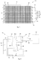
- Fig. 1 is used to describe forms of embodiment of a device 10 to control the functioning of a heat exchanger 11, comprised, by way of example, in a plant or an apparatus for cooling and/or conditioning.
- the control device 10 comprises an electric generator 12 suitable to generate an electric quantity, such as a current and/or a tension, with suitable modulation and encoding method, and a high-frequency emission element 13, disposed in an emission point or zone, connected to the electric generator 12 and associable to the heat exchanger 11.
- an electric generator 12 suitable to generate an electric quantity, such as a current and/or a tension, with suitable modulation and encoding method
- a high-frequency emission element 13 disposed in an emission point or zone, connected to the electric generator 12 and associable to the heat exchanger 11.
- the emission element 13 is configured to generate an electromagnetic field, with suitable modulation and encoding, by means of the electric quantity generated by the electric generator 12.
- the emission element 13, in a preferred solution, can be disposed in a peripheral position even not in contact with, or only near, the heat exchanger 11, but such that the electromagnetic field emitted passes through parts of the heat exchanger 11.
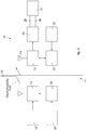
- the electric generator 12 can be a tension generator, as shown in figs. 1 and 2 , for example high-frequency alternate tension.
- the electric generator 12 can be, by way of example, an alternate current generator, which generates current for example with a square or sinusoidal wave shape, with suitable modulation and encoding, for example by means of a suitable encoded modulator 32 ( fig. 3 ) so as to create a real and proper signature on this signal until the signal is recognized uniquely and unequivocally even in the presence of disturbances of any type.
- an alternate current generator which generates current for example with a square or sinusoidal wave shape, with suitable modulation and encoding, for example by means of a suitable encoded modulator 32 ( fig. 3 ) so as to create a real and proper signature on this signal until the signal is recognized uniquely and unequivocally even in the presence of disturbances of any type.
- the emission element 13 is typically a metal conductor with adequate impedance.
- the emission element 13 has an elongated shape, as can be seen in the example shown in fig. 1 , and can be made, by way of example, with a cable, or a bar, suitable for the transmission of an electromagnetic field.
- the emission element 13 can be, for example, a plate, a mesh, a spiral or a solenoid.
- the control device 10 also comprises a detection element 14, disposed at a detection point or zone, distanced with respect to the emission element 13, associable to the heat exchanger 11 and configured to detect a value of the electromagnetic field received in the detection point, with respect to the value generated by the electromagnetic field in the emission point with a suitable de-modulation and de-coding method.
- the detection element 14 can be disposed in peripheral positions of the heat exchanger 11, advantageously distant from and/or opposite and/or external to the positions of the emission element 13, so that the electromagnetic field emitted by the emission element 13 and received by the detection element 14 passes through at least a part 18 (see fig. 3 again) of the heat exchanger 11.
- the detection element 14 is typically a metal conductor with impedance suitable to be used as a receiving antenna of the signal emitted by the transmission conductor of the emission element 13.
- the detection element 14 has an elongated shape, as can be seen in the example shown in fig. 1 , and can be made, by way of example, with a cable, or a bar, suitable for the transmission of an electromagnetic field.
- the detection element 14 can be for example a plate, a mesh, a spiral, a solenoid or a real antenna.
- the control device 10 also comprises a detector 15, connected to the detection element 14, and able, by means of a suitable method to de-modulate and de-code the signal received, to determine the functioning conditions of the heat exchanger 11 as a function of the electromagnetic field detected in the detection point or zone by the detector element 14.
- the measuring mean 19 is an amperometer configured to measure a signal quantity on the detection element 14, as generated by the electromagnetic field emitted by the emission element 13.
- the measuring mean 19 can be, by way of example, a voltmeter, able to detect a difference in potential generated by the electromagnetic field received.
- the control action of the control device 10, according to the form of embodiment in figs. 1 and 2 allows to verify the presence of determinate materials, for example deposited in the zone 18 of the heat exchanger 11 through which the electromagnetic emission field passes, until it reaches the detection element.
- These electromagnetic properties can be, by way of non-restrictive example, the electric permittivity ⁇ , also called dielectric constant, the magnetic susceptibility or the capacity.
- control device 10 is configured to detect the electric permittivity ⁇ in the heat exchanger 11.
- the emission element 13 and the detection element 14 are comparable to two plates of a capacitor, while the heat exchanger 11 can be considered as a dielectric material interposed between the plates, that therefore function as transmission and reception antennae.
- the capacity of the capacitor C is proportional to the electric permittivity ⁇ .
- Said electromagnetic field generated is due to the tension created by the generator 12, suitably modulated and encoded, which is equal to the difference in potential V between the plates of the capacitor in the capacity detection methods.
- the quantity of field transmitted in the form of current circulating in the detection element 14 measured by the amperometer 19 is measured.
- the electric permittivity ⁇ quantifies the tendency of a material to contrast the intensity of the electromagnetic field that passes through it.
- the electric permittivity ⁇ can be considered as the product of the relative permittivity ⁇ r , dependent on the materials affected by the electromagnetic field generated, and of the permittivity of the vacuum ⁇ 0 , not dependent on the materials.
- ⁇ ⁇ r • ⁇ 0
- Ice in particular, is a material that has a high relative permittivity ⁇ r , and consequently a high electric permittivity ⁇ , that leads to consistent variations in the electromagnetic field detected, if present, even in reduced quantities, inside the heat exchanger 11.
- the relative permittivity ⁇ r of ice has a value of about 86.4 against a relative permittivity ⁇ r of the air of 1.00059.
- the control device 10 is therefore particularly effective to detect the presence of ice inside the heat exchanger 11.
- the variation in thickness of the layer of ice also leads to a proportional variation in the electric permittivity ⁇ .
- control device 10 can be used to detect the presence of water, in the form of condensation or frost for example, or other types of materials, for example encrustations, lime scale, dirt, dust or other.
- control device 10 can also include a frequency generator 21 configured to determine at least a frequency with which the electric generator 12 operates.
- the electric permittivity ⁇ is indeed a function of the frequency of the electromagnetic field, generated and transmitted, and consequently, depending on the control to be carried out in the heat exchanger 11, a suitable frequency of the emission element 13 can be set, in different forms of embodiment, by means of the electric generator 12.
- the electromagnetic field emitted by the emission element 13 advantageously has a frequency suitable for the purpose and a precise and stable power.
- control device 10 can also comprise the encoded modulator 32, connected to the emission element 13 and configured to modulate the electromagnetic field produced, so that it can be distinct from the detection element 14 even in the presence of disturbing signals, such as for example background noises that can modify the characteristics thereof.
- the encoded modulator 32 connected to the emission element 13 and configured to modulate the electromagnetic field produced, so that it can be distinct from the detection element 14 even in the presence of disturbing signals, such as for example background noises that can modify the characteristics thereof.
- the frequency generator 21 can also provide means to interface with a user to modify the frequency supplied thereby.
- the emission element 13 and the detection element 14 can use wire antennas, and can be mounted on a single physical structure ( fig. 4a ), with the corresponding antenna elements in communication with each other; or on two physically separate units ( fig. 4b ) with a receiving unit equipped with a dipole wire antenna to improve reception; or again they can be separate and near ( fig. 4c ) with the receiving unit equipped with dipole wire antenna to improve reception, or they can be separate and distanced with the receiving unit equipped with a wire antenna.
- the frequency generator 21 is comprised in the electric generator 12.
- the frequency generator 21 can determine a frequency from about 100 kHz to 1 GHz, more preferably from 1 MHz to 500 MHz, even more preferably from 10 MHz to 50 MHz.
- frequencies can be set, by means of the frequency generator 21, comprised in the spectrum of microwaves, to detect determinate materials.
- the electromagnetic field detected on the detection element 14, given the same electromagnetic field generated can be a function, by way of example, of the magnetic susceptibility.
- At least an emission element 13 and/or a detection element 14 of a spiral and/or solenoid shape can be provided.
- the control device 10 can also comprise a processing element 20, able to process data coming at least from the measuring mean 19 and/or from the detection element 14 using a suitable modulation and encoding method.
- control device 10 also comprises the encoded de-modulator 33, configured, as we said, to recognize the electromagnetic field generated by the emission element 13.
- the signal detected is transmitted to the processing element 20 which, by way of example, can compare the quantity measured by the measuring mean 19 and at least a threshold quantity.
- the processing element 20 can allow to trace the development of the quantity over time, measured by the measuring mean 19, possibly providing to generate graphs.
- the processing element 20 can, for example, allow to obtain information on the composition of the materials, analyzing the quantity measured.
- the heat exchanger 11 is made as a bundle of tubes, and comprises a coil 16 in which a heat-carrying liquid flows.
- the coil 16 is made of rectilinear tubular elements 17 connected by U shaped curved pipes.
- a plurality of fins 18 (which identify, in this example, the generic zone 18 of fig. 3 which the electromagnetic field passes through), that is, metal plates, which have the function of increasing the heat exchange surface, are solidly associated to the coil 16, transversely to the longitudinal extension of the tubular elements 17.
- the control device 10 in accordance with the form of embodiment in fig. 1 , can be used to detect the presence of layers of ice that can be deposited on the fins 18 or on the coil 16.
- control device 10 can be used to detect the presence of water, for example in the form of condensation, or other types of materials deposited on the fins 18 or on the coil 16.
- the emission element 13 and the detection element 14 are stably associated to the heat exchanger 11 and pass through it, from one lateral end to the other.
- the electromagnetic field generated by the emission element 13 has concentric field lines, with the center in correspondence to the section of the emission element 13 itself.
- the emission element 13 and the detection element 14, in the case shown, are disposed parallel to each other.
- the emission element 13 and the detection element 14 are disposed respectively at the upper and lower end of the heat exchanger 11, that is, with a peripheral disposition on the heat exchanger 11.
- This peripheral disposition allows to pass through, with the electromagnetic field generated by the emission element 13, an ample portion of the heat exchanger 11 before detection by the detection element 14.
- through holes can be provided on the fins 18.
- control device 10 can comprise monitoring means 22 to allow a user to monitor the functioning of the heat exchanger 11 ( fig. 1 ).
- the monitoring means 22 can allow to display the current and/or tension values detected by the detector 15.
- the monitoring means 22 can signal, for example using light indicators, liquid crystal displays or audio diffusion means, the presence of ice, frost and/or condensation in the heat exchanger 11.
- the control device 10 can also comprise adaptation means, which allow to adapt the electric quantities exiting from the detection element 14 to those sustainable and/or supportable by the detector 15 and/or by the monitoring means 22.
- the adaptation means can comprise, by way of example, suitable detection, modulation and encoding circuits, filters, a preamplifier, an amplifier, an analog/digital converter, a transformer, or other device known in the state of the art.
- the adaptation means can be integrated in the detector 15.
- a plurality of emission elements 13 can be provided, configured to generate a plurality of electromagnetic fields and associated to the same heat exchanger 11 and/or parts of it.
- the generation of a plurality of electromagnetic fields, with different characteristics of frequency and/or intensity, can allow to detect the position of the ice with precision.
- electromagnetic fields can be generated at different frequencies, by different emission elements 13, and on the basis of the values detected on the detection element 14 paths can be identified in the heat exchanger with a different electric permittivity ⁇ .
- a plurality of detection elements 14 can be provided, distanced from each other, to detect with greater precision changes in electric permittivity ⁇ , in determinate directions, and to identify, for example, the position of the ice in the heat exchanger 11.
- the detection elements 14 can communicate the possible presence of ice to a single emission element 13, so that the latter is able to identify the specific position where the ice has formed.
- the control device 10 comprises a feeder 23 suitable to supply energy at least to the electric generator 12 and to the detector 15.
- the measuring mean 19 and the processing element 20 are connected by a first internal line 24a for the transmission of data.
- the control device 10 in the form of embodiment in fig. 2 , also comprises external communication means 27, for the transmission of data to external apparatuses, in this case a heater 31.
- the heater 31, also called defrosting device, can be configured to supply heat to the heat exchanger 11, by way of example, selectively making a fluid flow at high temperature in the coil 16, or activating an electric resistance.
- the external communication means 27 comprise a first external line 29 and a second external line 30, which achieve a connection between the processing element 20 and the heater 31.
- the external communication means 27 also comprise a transmitter 28, configured to send data on the external lines 29, 30.
- the processing element 20 is configured to compare, after a suitable detection, de-modulation and de-coding, the quantity measured by the measuring mean 19 with at least a threshold quantity.
- Supplementary internal lines 26 can also be provided, for the connection, for example, of the electric generator 12 and the detector 15 to the feeder 23.
- the presence of ice is detected by setting a first threshold quantity and a second threshold quantity: when these are exceeded, a semi-defrosting command and a defrosting command are respectively sent to the heater 31.
- the first threshold quantity is set to detect a smaller amount of ice than the amount of ice detected with the second threshold quantity, and consequently the heater 31 delivers a smaller amount of heat with the semi-defrosting command, compared with the defrosting command.
- the difference between the electromagnetic field generated and the electromagnetic field detected can be used as the threshold quantity.
- the first external line 29 and the second external line 30 have a parallel configuration, respectively sending the semi-defrosting command and the defrosting command.
- a timing device can also be provided, not shown, configured to achieve timed activations of the heater 31, to further reduce the probability of ice deposits.
Landscapes
- Engineering & Computer Science (AREA)
- Physics & Mathematics (AREA)
- Thermal Sciences (AREA)
- Mechanical Engineering (AREA)
- General Engineering & Computer Science (AREA)
- Air Conditioning Control Device (AREA)
- Compression-Type Refrigeration Machines With Reversible Cycles (AREA)
- Steam Or Hot-Water Central Heating Systems (AREA)
Applications Claiming Priority (2)
| Application Number | Priority Date | Filing Date | Title |
|---|---|---|---|
| IT000108A ITUD20130108A1 (it) | 2013-08-13 | 2013-08-13 | Dispositivo di controllo del funzionamento di uno scambiatore di calore, scambiatore di calore comprendente detto dispositivo e relativo procedimento di controllo |
| PCT/IB2014/063875 WO2015022638A1 (en) | 2013-08-13 | 2014-08-12 | Device to control the functioning of a heat exchanger, heat exchanger comprising said device and corresponding control method based on the measurement of an electromagnetic field |
Publications (2)
| Publication Number | Publication Date |
|---|---|
| EP3033580A1 EP3033580A1 (en) | 2016-06-22 |
| EP3033580B1 true EP3033580B1 (en) | 2018-03-21 |
Family
ID=49447741
Family Applications (1)
| Application Number | Title | Priority Date | Filing Date |
|---|---|---|---|
| EP14777833.6A Not-in-force EP3033580B1 (en) | 2013-08-13 | 2014-08-12 | Device to control the functioning of a heat exchanger, heat exchanger comprising said device and corresponding control method based on measuring an electromagnetic field |
Country Status (4)
| Country | Link |
|---|---|
| US (1) | US20160195347A1 (it) |
| EP (1) | EP3033580B1 (it) |
| IT (1) | ITUD20130108A1 (it) |
| WO (1) | WO2015022638A1 (it) |
Families Citing this family (3)
| Publication number | Priority date | Publication date | Assignee | Title |
|---|---|---|---|---|
| SG11201810307VA (en) | 2016-05-27 | 2018-12-28 | Carrier Corp | Method for determining reduced airflow in transport refrigeration system |
| GB2576185B (en) * | 2018-08-08 | 2022-07-20 | Oxford Instruments Nanotechnology Tools Ltd | Noise reduction method for a cryogenic cooling system |
| WO2024200763A1 (de) * | 2023-03-30 | 2024-10-03 | Graforce Gmbh | Wärmetauscher |
Citations (1)
| Publication number | Priority date | Publication date | Assignee | Title |
|---|---|---|---|---|
| JPS60155876A (ja) * | 1984-01-25 | 1985-08-15 | 株式会社日立製作所 | 冷蔵庫の霜検知装置 |
Family Cites Families (14)
| Publication number | Priority date | Publication date | Assignee | Title |
|---|---|---|---|---|
| US563751A (en) * | 1896-07-14 | Pneumatic track-sander | ||
| US4374709A (en) | 1980-05-01 | 1983-02-22 | Occidental Chemical Corporation | Process for plating polymeric substrates |
| US4347709A (en) * | 1981-01-19 | 1982-09-07 | Honeywell Inc. | Demand defrost sensor |
| IT1255045B (it) * | 1992-03-31 | 1995-10-17 | Whirlpool Italia | Metodo e dispositivo per rilevare e controllare la formazione di brina su un evaporatore di un refrigeratore |
| DE69317115T2 (de) * | 1993-09-22 | 1999-04-15 | Whirlpool Europe B.V., Veldhoven | Verfahren zur dynamischen Kontrolle der Eisbildung an einem Kühlschrankverdampfer und Kühlschrank in dem das Verfahren angewandt ist |
| IT240417Y1 (it) * | 1996-01-30 | 2001-04-02 | Whirlpool Europ S R L | Dispositivo per rilevare la formazione di brina e per eliminarlaper riscaldamento particolarmente per evaporatori di frigoriferi |
| JP2001264446A (ja) * | 2000-03-22 | 2001-09-26 | Tdk Corp | 静電容量型物体検知装置及び冷却器の霜取り装置 |
| CA2776382C (en) * | 2009-10-02 | 2018-01-30 | The Controls Group, Inc. | Removal of an accumulated frozen substance from a cooling unit |
| US20110185755A1 (en) * | 2010-01-29 | 2011-08-04 | Samsung Electronics Co., Ltd. | Cooling apparatus and frost detecting method thereof |
| KR101907166B1 (ko) * | 2011-12-30 | 2018-10-15 | 삼성전자주식회사 | 냉장고 |
| US9243833B2 (en) * | 2013-11-05 | 2016-01-26 | General Electric Company | Ice making system for a refrigerator appliance and a method for determining an ice level within an ice bucket |
| US10502597B2 (en) * | 2016-04-10 | 2019-12-10 | Forum Us, Inc. | Monitored heat exchanger system |
| US10545002B2 (en) * | 2016-04-10 | 2020-01-28 | Forum Us, Inc. | Method for monitoring a heat exchanger unit |
| US10197342B2 (en) * | 2016-06-24 | 2019-02-05 | Hamilton Sundstrand Corporation | Heat exchanger system and method of operation |
-
2013
- 2013-08-13 IT IT000108A patent/ITUD20130108A1/it unknown
-
2014
- 2014-08-12 WO PCT/IB2014/063875 patent/WO2015022638A1/en not_active Ceased
- 2014-08-12 EP EP14777833.6A patent/EP3033580B1/en not_active Not-in-force
- 2014-08-12 US US14/911,800 patent/US20160195347A1/en not_active Abandoned
Patent Citations (1)
| Publication number | Priority date | Publication date | Assignee | Title |
|---|---|---|---|---|
| JPS60155876A (ja) * | 1984-01-25 | 1985-08-15 | 株式会社日立製作所 | 冷蔵庫の霜検知装置 |
Also Published As
| Publication number | Publication date |
|---|---|
| US20160195347A1 (en) | 2016-07-07 |
| WO2015022638A1 (en) | 2015-02-19 |
| EP3033580A1 (en) | 2016-06-22 |
| ITUD20130108A1 (it) | 2015-02-14 |
Similar Documents
| Publication | Publication Date | Title |
|---|---|---|
| US9766283B2 (en) | Transformer fault detection apparatus and method | |
| EP3033580B1 (en) | Device to control the functioning of a heat exchanger, heat exchanger comprising said device and corresponding control method based on measuring an electromagnetic field | |
| Tariq et al. | Wireless sensor networks for leakage detection in underground pipelines: a survey paper | |
| JP3579868B2 (ja) | センサ装置、設定装置、読み出し装置及び物品管理システム | |
| US10101288B2 (en) | Wireless impedance spectrometer | |
| US6470734B2 (en) | Method and arrangement for measuring fluid | |
| CN109171731B (zh) | 一种无接触呼吸检测方法 | |
| RU2012116010A (ru) | Системы и способы измерения импеданса для определения компонентов твердых и текучих объектов | |
| JP2013512414A5 (it) | ||
| US20090147824A1 (en) | Wireless remote passive temperature sensor for monitoring food | |
| US10101187B2 (en) | Flowmeter, dialysis machine and medicinal solution injection device | |
| EP3218700B1 (en) | Multi-phase fluid fraction measurement | |
| CN105299985A (zh) | 温度调节系统和对温度调节系统进行除冰的方法 | |
| CN103604842A (zh) | 高压电气设备内sf6气体密度、微水含量在线监测装置 | |
| CN210071169U (zh) | 基于lc谐振的电缆中间接头测温装置及电缆中间接头 | |
| CN104729627A (zh) | 油水界面测量传感器 | |
| US20230184354A1 (en) | Composite hose with radio frequency identification (rfid) enabled sensor | |
| KR20090109544A (ko) | 배관 누설 위치결정 방법 | |
| CN107766906A (zh) | 基于高频无源rfid标签的钢腐蚀检测系统及检测方法 | |
| WO2014103316A1 (ja) | 非接触給電装置 | |
| JP2012037537A (ja) | 配管診断装置、及び空気調和機 | |
| EP2952887A1 (en) | Sensor, measuring device, and measuring method for measuring the permittivity of a sample using a helix conductor | |
| CN110649938B (zh) | 一种全频段窄带物联网电调谐管道感应天线 | |
| Deif et al. | Out-of-sight salt-water concentration sensing using chipless-RFID for pipeline coating integrity | |
| GB2470225A (en) | Contactless microenvironment sensor |
Legal Events
| Date | Code | Title | Description |
|---|---|---|---|
| PUAI | Public reference made under article 153(3) epc to a published international application that has entered the european phase |
Free format text: ORIGINAL CODE: 0009012 |
|
| 17P | Request for examination filed |
Effective date: 20160229 |
|
| AK | Designated contracting states |
Kind code of ref document: A1 Designated state(s): AL AT BE BG CH CY CZ DE DK EE ES FI FR GB GR HR HU IE IS IT LI LT LU LV MC MK MT NL NO PL PT RO RS SE SI SK SM TR |
|
| AX | Request for extension of the european patent |
Extension state: BA ME |
|
| DAX | Request for extension of the european patent (deleted) | ||
| GRAP | Despatch of communication of intention to grant a patent |
Free format text: ORIGINAL CODE: EPIDOSNIGR1 |
|
| GRAJ | Information related to disapproval of communication of intention to grant by the applicant or resumption of examination proceedings by the epo deleted |
Free format text: ORIGINAL CODE: EPIDOSDIGR1 |
|
| GRAP | Despatch of communication of intention to grant a patent |
Free format text: ORIGINAL CODE: EPIDOSNIGR1 |
|
| INTG | Intention to grant announced |
Effective date: 20170616 |
|
| INTG | Intention to grant announced |
Effective date: 20170630 |
|
| GRAS | Grant fee paid |
Free format text: ORIGINAL CODE: EPIDOSNIGR3 |
|
| GRAA | (expected) grant |
Free format text: ORIGINAL CODE: 0009210 |
|
| AK | Designated contracting states |
Kind code of ref document: B1 Designated state(s): AL AT BE BG CH CY CZ DE DK EE ES FI FR GB GR HR HU IE IS IT LI LT LU LV MC MK MT NL NO PL PT RO RS SE SI SK SM TR |
|
| REG | Reference to a national code |
Ref country code: GB Ref legal event code: FG4D |
|
| REG | Reference to a national code |
Ref country code: CH Ref legal event code: EP |
|
| REG | Reference to a national code |
Ref country code: AT Ref legal event code: REF Ref document number: 981584 Country of ref document: AT Kind code of ref document: T Effective date: 20180415 |
|
| REG | Reference to a national code |
Ref country code: IE Ref legal event code: FG4D |
|
| REG | Reference to a national code |
Ref country code: DE Ref legal event code: R096 Ref document number: 602014022684 Country of ref document: DE |
|
| REG | Reference to a national code |
Ref country code: FR Ref legal event code: PLFP Year of fee payment: 5 |
|
| REG | Reference to a national code |
Ref country code: NL Ref legal event code: MP Effective date: 20180321 |
|
| PG25 | Lapsed in a contracting state [announced via postgrant information from national office to epo] |
Ref country code: NO Free format text: LAPSE BECAUSE OF FAILURE TO SUBMIT A TRANSLATION OF THE DESCRIPTION OR TO PAY THE FEE WITHIN THE PRESCRIBED TIME-LIMIT Effective date: 20180621 Ref country code: CY Free format text: LAPSE BECAUSE OF FAILURE TO SUBMIT A TRANSLATION OF THE DESCRIPTION OR TO PAY THE FEE WITHIN THE PRESCRIBED TIME-LIMIT Effective date: 20180321 Ref country code: LT Free format text: LAPSE BECAUSE OF FAILURE TO SUBMIT A TRANSLATION OF THE DESCRIPTION OR TO PAY THE FEE WITHIN THE PRESCRIBED TIME-LIMIT Effective date: 20180321 Ref country code: HR Free format text: LAPSE BECAUSE OF FAILURE TO SUBMIT A TRANSLATION OF THE DESCRIPTION OR TO PAY THE FEE WITHIN THE PRESCRIBED TIME-LIMIT Effective date: 20180321 Ref country code: FI Free format text: LAPSE BECAUSE OF FAILURE TO SUBMIT A TRANSLATION OF THE DESCRIPTION OR TO PAY THE FEE WITHIN THE PRESCRIBED TIME-LIMIT Effective date: 20180321 |
|
| REG | Reference to a national code |
Ref country code: LT Ref legal event code: MG4D |
|
| REG | Reference to a national code |
Ref country code: AT Ref legal event code: MK05 Ref document number: 981584 Country of ref document: AT Kind code of ref document: T Effective date: 20180321 |
|
| PG25 | Lapsed in a contracting state [announced via postgrant information from national office to epo] |
Ref country code: GR Free format text: LAPSE BECAUSE OF FAILURE TO SUBMIT A TRANSLATION OF THE DESCRIPTION OR TO PAY THE FEE WITHIN THE PRESCRIBED TIME-LIMIT Effective date: 20180622 Ref country code: BG Free format text: LAPSE BECAUSE OF FAILURE TO SUBMIT A TRANSLATION OF THE DESCRIPTION OR TO PAY THE FEE WITHIN THE PRESCRIBED TIME-LIMIT Effective date: 20180621 Ref country code: RS Free format text: LAPSE BECAUSE OF FAILURE TO SUBMIT A TRANSLATION OF THE DESCRIPTION OR TO PAY THE FEE WITHIN THE PRESCRIBED TIME-LIMIT Effective date: 20180321 Ref country code: LV Free format text: LAPSE BECAUSE OF FAILURE TO SUBMIT A TRANSLATION OF THE DESCRIPTION OR TO PAY THE FEE WITHIN THE PRESCRIBED TIME-LIMIT Effective date: 20180321 Ref country code: SE Free format text: LAPSE BECAUSE OF FAILURE TO SUBMIT A TRANSLATION OF THE DESCRIPTION OR TO PAY THE FEE WITHIN THE PRESCRIBED TIME-LIMIT Effective date: 20180321 |
|
| PGFP | Annual fee paid to national office [announced via postgrant information from national office to epo] |
Ref country code: IT Payment date: 20180619 Year of fee payment: 5 |
|
| PG25 | Lapsed in a contracting state [announced via postgrant information from national office to epo] |
Ref country code: NL Free format text: LAPSE BECAUSE OF FAILURE TO SUBMIT A TRANSLATION OF THE DESCRIPTION OR TO PAY THE FEE WITHIN THE PRESCRIBED TIME-LIMIT Effective date: 20180321 Ref country code: ES Free format text: LAPSE BECAUSE OF FAILURE TO SUBMIT A TRANSLATION OF THE DESCRIPTION OR TO PAY THE FEE WITHIN THE PRESCRIBED TIME-LIMIT Effective date: 20180321 Ref country code: PL Free format text: LAPSE BECAUSE OF FAILURE TO SUBMIT A TRANSLATION OF THE DESCRIPTION OR TO PAY THE FEE WITHIN THE PRESCRIBED TIME-LIMIT Effective date: 20180321 Ref country code: RO Free format text: LAPSE BECAUSE OF FAILURE TO SUBMIT A TRANSLATION OF THE DESCRIPTION OR TO PAY THE FEE WITHIN THE PRESCRIBED TIME-LIMIT Effective date: 20180321 Ref country code: AL Free format text: LAPSE BECAUSE OF FAILURE TO SUBMIT A TRANSLATION OF THE DESCRIPTION OR TO PAY THE FEE WITHIN THE PRESCRIBED TIME-LIMIT Effective date: 20180321 Ref country code: EE Free format text: LAPSE BECAUSE OF FAILURE TO SUBMIT A TRANSLATION OF THE DESCRIPTION OR TO PAY THE FEE WITHIN THE PRESCRIBED TIME-LIMIT Effective date: 20180321 |
|
| PGFP | Annual fee paid to national office [announced via postgrant information from national office to epo] |
Ref country code: DE Payment date: 20180809 Year of fee payment: 5 Ref country code: FR Payment date: 20180706 Year of fee payment: 5 |
|
| PG25 | Lapsed in a contracting state [announced via postgrant information from national office to epo] |
Ref country code: AT Free format text: LAPSE BECAUSE OF FAILURE TO SUBMIT A TRANSLATION OF THE DESCRIPTION OR TO PAY THE FEE WITHIN THE PRESCRIBED TIME-LIMIT Effective date: 20180321 Ref country code: SM Free format text: LAPSE BECAUSE OF FAILURE TO SUBMIT A TRANSLATION OF THE DESCRIPTION OR TO PAY THE FEE WITHIN THE PRESCRIBED TIME-LIMIT Effective date: 20180321 Ref country code: SK Free format text: LAPSE BECAUSE OF FAILURE TO SUBMIT A TRANSLATION OF THE DESCRIPTION OR TO PAY THE FEE WITHIN THE PRESCRIBED TIME-LIMIT Effective date: 20180321 |
|
| PGFP | Annual fee paid to national office [announced via postgrant information from national office to epo] |
Ref country code: CZ Payment date: 20180820 Year of fee payment: 5 |
|
| PG25 | Lapsed in a contracting state [announced via postgrant information from national office to epo] |
Ref country code: PT Free format text: LAPSE BECAUSE OF FAILURE TO SUBMIT A TRANSLATION OF THE DESCRIPTION OR TO PAY THE FEE WITHIN THE PRESCRIBED TIME-LIMIT Effective date: 20180723 |
|
| REG | Reference to a national code |
Ref country code: DE Ref legal event code: R097 Ref document number: 602014022684 Country of ref document: DE |
|
| PLBE | No opposition filed within time limit |
Free format text: ORIGINAL CODE: 0009261 |
|
| STAA | Information on the status of an ep patent application or granted ep patent |
Free format text: STATUS: NO OPPOSITION FILED WITHIN TIME LIMIT |
|
| PG25 | Lapsed in a contracting state [announced via postgrant information from national office to epo] |
Ref country code: DK Free format text: LAPSE BECAUSE OF FAILURE TO SUBMIT A TRANSLATION OF THE DESCRIPTION OR TO PAY THE FEE WITHIN THE PRESCRIBED TIME-LIMIT Effective date: 20180321 |
|
| 26N | No opposition filed |
Effective date: 20190102 |
|
| PG25 | Lapsed in a contracting state [announced via postgrant information from national office to epo] |
Ref country code: MC Free format text: LAPSE BECAUSE OF FAILURE TO SUBMIT A TRANSLATION OF THE DESCRIPTION OR TO PAY THE FEE WITHIN THE PRESCRIBED TIME-LIMIT Effective date: 20180321 |
|
| REG | Reference to a national code |
Ref country code: CH Ref legal event code: PL |
|
| PG25 | Lapsed in a contracting state [announced via postgrant information from national office to epo] |
Ref country code: LU Free format text: LAPSE BECAUSE OF NON-PAYMENT OF DUE FEES Effective date: 20180812 Ref country code: CH Free format text: LAPSE BECAUSE OF NON-PAYMENT OF DUE FEES Effective date: 20180831 Ref country code: LI Free format text: LAPSE BECAUSE OF NON-PAYMENT OF DUE FEES Effective date: 20180831 |
|
| REG | Reference to a national code |
Ref country code: BE Ref legal event code: MM Effective date: 20180831 |
|
| REG | Reference to a national code |
Ref country code: IE Ref legal event code: MM4A |
|
| PG25 | Lapsed in a contracting state [announced via postgrant information from national office to epo] |
Ref country code: SI Free format text: LAPSE BECAUSE OF FAILURE TO SUBMIT A TRANSLATION OF THE DESCRIPTION OR TO PAY THE FEE WITHIN THE PRESCRIBED TIME-LIMIT Effective date: 20180321 |
|
| PG25 | Lapsed in a contracting state [announced via postgrant information from national office to epo] |
Ref country code: IE Free format text: LAPSE BECAUSE OF NON-PAYMENT OF DUE FEES Effective date: 20180812 |
|
| PG25 | Lapsed in a contracting state [announced via postgrant information from national office to epo] |
Ref country code: BE Free format text: LAPSE BECAUSE OF NON-PAYMENT OF DUE FEES Effective date: 20180831 |
|
| PG25 | Lapsed in a contracting state [announced via postgrant information from national office to epo] |
Ref country code: MT Free format text: LAPSE BECAUSE OF NON-PAYMENT OF DUE FEES Effective date: 20180812 |
|
| REG | Reference to a national code |
Ref country code: DE Ref legal event code: R119 Ref document number: 602014022684 Country of ref document: DE |
|
| PG25 | Lapsed in a contracting state [announced via postgrant information from national office to epo] |
Ref country code: TR Free format text: LAPSE BECAUSE OF FAILURE TO SUBMIT A TRANSLATION OF THE DESCRIPTION OR TO PAY THE FEE WITHIN THE PRESCRIBED TIME-LIMIT Effective date: 20180321 |
|
| PGFP | Annual fee paid to national office [announced via postgrant information from national office to epo] |
Ref country code: GB Payment date: 20200228 Year of fee payment: 6 |
|
| PG25 | Lapsed in a contracting state [announced via postgrant information from national office to epo] |
Ref country code: CZ Free format text: LAPSE BECAUSE OF NON-PAYMENT OF DUE FEES Effective date: 20190812 |
|
| PG25 | Lapsed in a contracting state [announced via postgrant information from national office to epo] |
Ref country code: MK Free format text: LAPSE BECAUSE OF NON-PAYMENT OF DUE FEES Effective date: 20180321 Ref country code: HU Free format text: LAPSE BECAUSE OF FAILURE TO SUBMIT A TRANSLATION OF THE DESCRIPTION OR TO PAY THE FEE WITHIN THE PRESCRIBED TIME-LIMIT; INVALID AB INITIO Effective date: 20140812 |
|
| PG25 | Lapsed in a contracting state [announced via postgrant information from national office to epo] |
Ref country code: DE Free format text: LAPSE BECAUSE OF NON-PAYMENT OF DUE FEES Effective date: 20200303 Ref country code: FR Free format text: LAPSE BECAUSE OF NON-PAYMENT OF DUE FEES Effective date: 20190831 Ref country code: IS Free format text: LAPSE BECAUSE OF FAILURE TO SUBMIT A TRANSLATION OF THE DESCRIPTION OR TO PAY THE FEE WITHIN THE PRESCRIBED TIME-LIMIT Effective date: 20180721 |
|
| PG25 | Lapsed in a contracting state [announced via postgrant information from national office to epo] |
Ref country code: IT Free format text: LAPSE BECAUSE OF NON-PAYMENT OF DUE FEES Effective date: 20190812 |
|
| GBPC | Gb: european patent ceased through non-payment of renewal fee |
Effective date: 20200812 |
|
| PG25 | Lapsed in a contracting state [announced via postgrant information from national office to epo] |
Ref country code: GB Free format text: LAPSE BECAUSE OF NON-PAYMENT OF DUE FEES Effective date: 20200812 |