EP3033584B1 - Système de missile à capacité de navigation basée sur un traitement d'images - Google Patents
Système de missile à capacité de navigation basée sur un traitement d'images Download PDFInfo
- Publication number
- EP3033584B1 EP3033584B1 EP14835900.3A EP14835900A EP3033584B1 EP 3033584 B1 EP3033584 B1 EP 3033584B1 EP 14835900 A EP14835900 A EP 14835900A EP 3033584 B1 EP3033584 B1 EP 3033584B1
- Authority
- EP
- European Patent Office
- Prior art keywords
- missile
- target
- imaging sensor
- subsystem
- motion
- Prior art date
- Legal status (The legal status is an assumption and is not a legal conclusion. Google has not performed a legal analysis and makes no representation as to the accuracy of the status listed.)
- Active
Links
Images

Classifications
-
- G—PHYSICS
- G05—CONTROLLING; REGULATING
- G05D—SYSTEMS FOR CONTROLLING OR REGULATING NON-ELECTRIC VARIABLES
- G05D1/00—Control of position, course, altitude or attitude of land, water, air or space vehicles, e.g. using automatic pilots
- G05D1/10—Simultaneous control of position or course in three dimensions
- G05D1/107—Simultaneous control of position or course in three dimensions specially adapted for missiles
-
- F—MECHANICAL ENGINEERING; LIGHTING; HEATING; WEAPONS; BLASTING
- F41—WEAPONS
- F41G—WEAPON SIGHTS; AIMING
- F41G7/00—Direction control systems for self-propelled missiles
- F41G7/007—Preparatory measures taken before the launching of the guided missiles
-
- F—MECHANICAL ENGINEERING; LIGHTING; HEATING; WEAPONS; BLASTING
- F41—WEAPONS
- F41G—WEAPON SIGHTS; AIMING
- F41G7/00—Direction control systems for self-propelled missiles
- F41G7/008—Combinations of different guidance systems
-
- F—MECHANICAL ENGINEERING; LIGHTING; HEATING; WEAPONS; BLASTING
- F41—WEAPONS
- F41G—WEAPON SIGHTS; AIMING
- F41G7/00—Direction control systems for self-propelled missiles
- F41G7/20—Direction control systems for self-propelled missiles based on continuous observation of target position
- F41G7/22—Homing guidance systems
- F41G7/2206—Homing guidance systems using a remote control station
-
- F—MECHANICAL ENGINEERING; LIGHTING; HEATING; WEAPONS; BLASTING
- F41—WEAPONS
- F41G—WEAPON SIGHTS; AIMING
- F41G7/00—Direction control systems for self-propelled missiles
- F41G7/20—Direction control systems for self-propelled missiles based on continuous observation of target position
- F41G7/22—Homing guidance systems
- F41G7/2213—Homing guidance systems maintaining the axis of an orientable seeking head pointed at the target, e.g. target seeking gyro
-
- F—MECHANICAL ENGINEERING; LIGHTING; HEATING; WEAPONS; BLASTING
- F41—WEAPONS
- F41G—WEAPON SIGHTS; AIMING
- F41G7/00—Direction control systems for self-propelled missiles
- F41G7/20—Direction control systems for self-propelled missiles based on continuous observation of target position
- F41G7/22—Homing guidance systems
- F41G7/2253—Passive homing systems, i.e. comprising a receiver and do not requiring an active illumination of the target
-
- F—MECHANICAL ENGINEERING; LIGHTING; HEATING; WEAPONS; BLASTING
- F41—WEAPONS
- F41G—WEAPON SIGHTS; AIMING
- F41G7/00—Direction control systems for self-propelled missiles
- F41G7/20—Direction control systems for self-propelled missiles based on continuous observation of target position
- F41G7/22—Homing guidance systems
- F41G7/2273—Homing guidance systems characterised by the type of waves
- F41G7/2293—Homing guidance systems characterised by the type of waves using electromagnetic waves other than radio waves
-
- F—MECHANICAL ENGINEERING; LIGHTING; HEATING; WEAPONS; BLASTING
- F41—WEAPONS
- F41G—WEAPON SIGHTS; AIMING
- F41G7/00—Direction control systems for self-propelled missiles
- F41G7/20—Direction control systems for self-propelled missiles based on continuous observation of target position
- F41G7/30—Command link guidance systems
-
- F—MECHANICAL ENGINEERING; LIGHTING; HEATING; WEAPONS; BLASTING
- F41—WEAPONS
- F41G—WEAPON SIGHTS; AIMING
- F41G7/00—Direction control systems for self-propelled missiles
- F41G7/34—Direction control systems for self-propelled missiles based on predetermined target position data
- F41G7/343—Direction control systems for self-propelled missiles based on predetermined target position data comparing observed and stored data of target position or of distinctive marks along the path towards the target
-
- F—MECHANICAL ENGINEERING; LIGHTING; HEATING; WEAPONS; BLASTING
- F42—AMMUNITION; BLASTING
- F42B—EXPLOSIVE CHARGES, e.g. FOR BLASTING, FIREWORKS, AMMUNITION
- F42B15/00—Self-propelled projectiles or missiles, e.g. rockets; Guided missiles
- F42B15/01—Arrangements thereon for guidance or control
-
- G—PHYSICS
- G01—MEASURING; TESTING
- G01C—MEASURING DISTANCES, LEVELS OR BEARINGS; SURVEYING; NAVIGATION; GYROSCOPIC INSTRUMENTS; PHOTOGRAMMETRY OR VIDEOGRAMMETRY
- G01C21/00—Navigation; Navigational instruments not provided for in groups G01C1/00 - G01C19/00
- G01C21/10—Navigation; Navigational instruments not provided for in groups G01C1/00 - G01C19/00 by using measurements of speed or acceleration
- G01C21/12—Navigation; Navigational instruments not provided for in groups G01C1/00 - G01C19/00 by using measurements of speed or acceleration executed aboard the object being navigated; Dead reckoning
-
- G—PHYSICS
- G05—CONTROLLING; REGULATING
- G05D—SYSTEMS FOR CONTROLLING OR REGULATING NON-ELECTRIC VARIABLES
- G05D1/00—Control of position, course, altitude or attitude of land, water, air or space vehicles, e.g. using automatic pilots
- G05D1/0011—Control of position, course, altitude or attitude of land, water, air or space vehicles, e.g. using automatic pilots associated with a remote control arrangement
- G05D1/0038—Control of position, course, altitude or attitude of land, water, air or space vehicles, e.g. using automatic pilots associated with a remote control arrangement by providing the operator with simple or augmented images from one or more cameras located onboard the vehicle, e.g. tele-operation
-
- G—PHYSICS
- G01—MEASURING; TESTING
- G01S—RADIO DIRECTION-FINDING; RADIO NAVIGATION; DETERMINING DISTANCE OR VELOCITY BY USE OF RADIO WAVES; LOCATING OR PRESENCE-DETECTING BY USE OF THE REFLECTION OR RERADIATION OF RADIO WAVES; ANALOGOUS ARRANGEMENTS USING OTHER WAVES
- G01S5/00—Position-fixing by co-ordinating two or more direction or position line determinations; Position-fixing by co-ordinating two or more distance determinations
- G01S5/16—Position-fixing by co-ordinating two or more direction or position line determinations; Position-fixing by co-ordinating two or more distance determinations using electromagnetic waves other than radio waves
Definitions
- Patent publications GB2293067 and DE102007054950 disclose missiles which employ images of terrain matched to data derived from a geographical database to provide navigation capabilities prior to locking on to a target.
- DE4218600 discloses a system for determining motion parameters of a flying object by using an optical sensing system coupled to a neural network-based processor to generate motion vectors for the flying object.
- the present invention is a missile system and corresponding method for operating a guided missile, as set out in the appended claims.
- the present invention is a missile system and corresponding method which employ ego-motion processing of seeker images to provide navigation capabilities.
- FIGS. 1 and 2 show aspects of a missile system, constructed and operative according to an embodiment of the present invention.
- the missile system includes a missile 10 having a missile body 12 containing a seeker 14.
- Seeker 14 typically located at a nose portion of missile 10, includes an electro-optic imaging sensor 16.
- a control arrangement allows steering (manual or autonomous) of missile 10 along a flight path to a target.
- the invention relates to tactical missiles which are configured to operate without an onboard inertial navigation system and without onboard satellite positioning signal sensors, instead relying on images from the electro-optic imaging sensor 16 as a basis for guidance of the missile, manually or autonomously, towards the target.
- the present invention supplements the functionality of the missile by providing navigation functionality based upon ego-motion processing of images from seeker 14, thereby facilitating reliable navigation of missile 10 towards an initially obscured or otherwise non-trackable target location until the target becomes visible, or towards a target which is designated by its relative or real-world coordinates rather than by its location on the video.
- the missile system of the present invention further includes a navigation subsystem receiving the images from imaging sensor 16.
- the navigation subsystem may be implemented as an onboard navigation subsystem 26 a , which is part of an onboard processing system 20, or as a remote navigation subsystem 26 b , which is part of a remote processing system 36 (shown in FIG. 2 and described further below), or may be distributed between the onboard and remote systems.
- the navigation subsystem 26 a and/or 26 b are configured to co-process images from imaging sensor 16 to derive ego-motion of the missile body relative to a region viewed by the imaging sensor, and to derive from the ego-motion a calculated target direction from the missile to a target.
- the present invention makes a major contribution to the functionality of tactical electro-optic missiles. Specifically, by use of ego-motion processing applied to images derived from the seeker imaging sensor, the present invention provides navigation capabilities to what is typically a relatively low-cost missile without requiring addition of dedicated hardware components such as are typically used in more expensive missiles, and without dependence on GPS during flight. This and other advantages of the present invention will be better understood with reference to the drawings and the following detailed description.
- Ego motion processing essentially tracks the apparent motion of stationary features appearing in two or more views from different locations, and derives the motion of the camera relative to the tracked features. Where the area viewed by the imaging sensor changes significantly, daisy-chaining of pose estimations can be used to determine new positions relative to features which have now passed from view.
- ego-motion processing for navigating an aerial vehicle as described in the above-referenced documents employs a camera with a wide field of view rigidly fixed to the airframe of the aerial vehicle to as to point generally perpendicular to the direction of travel.
- These parameters rigidly fixed camera, wide field of view, and directed perpendicular to direction of travel
- a downwards or sideways viewing direction ensures sufficient relative motion to facilitate ego-motion derivation
- a wide field of view ensures coverage of sufficient trackable features within the field of view
- a rigidly mounted camera to ensure one-to-one mapping between the derived camera position and the position of the aerial vehicle airframe.
- the imaging sensor of an electro-optic missile seeker is typically a narrow field-of-view sensor (typically less than 15° viewing angle, and often less than about 5°) which is typically dynamically mounted on a gimbal arrangement relative to the missile body, and which looks in a generally forward direction towards the region of a target.
- the present invention teaches that the imaging sensor of an electro-optic missile seeker, despite being far from the above assumed-optimal parameters, has surprisingly been found to be a very effective basis for ego-motion processing.
- Ego motion processing determines movement of an imaging device relative to features within the field of view, subject to a scaling factor, but cannot be used for absolute navigation in the physical world without some external data available to anchor the derived camera pose in the real world and to derive the scaling factor. For this reason, most implementations of navigation systems employing ego motion processing combine the technique with at least one additional modality of navigation, such as GPS sensors, image matching and/or inertial navigation systems.
- certain particularly preferred implementations of the present invention employ ego motion processing as a sole navigation modality, deriving real world coordinates from data provided prior to launch, and deriving the scaling factor either from pre-launch data or from measurements taken immediately after launch.
- ego motion processing deriving real world coordinates from data provided prior to launch
- scaling factor either from pre-launch data or from measurements taken immediately after launch.
- This navigation modality is optionally supplemented by a tracking-based homing modality which takes over control of missile steering during closing stages of a flight path to the target.
- vigation is used herein to refer to control of the path of the missile to guide it to a defined relative or real-world location
- homoing is used herein to refer to control of the path of the missile to close on a tracked target.
- FIG. 1 shows schematically various components of an implementation of missile 10 while FIG. 2 shows schematically other components of an implementation of the missile system.
- imaging sensor 16 is typically a thermal imaging camera, which may be cooled or uncooled. Additionally or alternatively, a camera sensitive to visible and/or near IR may be used. Imaging sensor 16 is typically supported by a gimbal arrangement 18 so as to be movable relative to missile body 10, as is common practice in electro-optic missiles.
- the gimbal arrangement may be a two-axis or three-axis gimbal arrangement, and may employ various geometrical arrangements of the gimbal axes suitable for use against stationary or slow-moving targets, as is well known in the art.
- missile 10 also includes an onboard processing system 20, including one or more processor (not shown) and data storage components (not shown), configured to provide a tracking subsystem 22 for tracking an object in images received from the imaging sensor and generating a tracked target direction.
- tracking subsystem 22 provides closed loop control of gimbal arrangement 18 to maintain imaging sensor 16 aligned with a tracked target, such that the gimbal angles themselves define the tracked target direction.
- Onboard processing system 20 also typically provides a guidance subsystem 24 configured to actuate steering actuators (typically electro-mechanical actuators linked to aerodynamic control surfaces or pyrotechnic steering actuators 28) to guide missile 10 along a flight path to a target based at least in part on the tracked target direction.
- steering actuators typically electro-mechanical actuators linked to aerodynamic control surfaces or pyrotechnic steering actuators 28
- Missile 10 also typically includes a payload 30, one or more stages of a propulsion system 32, and optionally components of a wired or wireless communications subsystem 34. Although illustrated herein in the context of a missile with onboard tracking and guidance capabilities, it should be noted that the invention is also applicable to a remotely controlled missile without onboard tracking and guidance capabilities.
- the navigation subsystem 26 a and/or 26 b is preferably initiated prior to launch with the geographical starting position and orientation of the missile.
- the source of this information is not critical to the present invention, and it may be provided or derived in various ways.
- launcher 38 is shown here with a subsystem 44 including components such as a GPS (or equivalent) receiver and/or a system for geographic registration for deriving the position and orientation of the launcher, and hence also the missile, prior to launch.
- geographic location may be determined by GPS, and angular orientation may be determined by use of a digital compass and a digital level sensor. Additionally, or alternatively, manual or automated triangulation techniques relative to other permanent or temporary known location reference points may be used, supported by suitable hardware, as is known in the art. Additionally, or alternatively, an imaging or ranging system can be used to determine or refine determination of the launcher position and orientation relative to sighted landmarks or geographic features identified, manually or automatically, in a geographic database including a digital terrain map (DTM). All of the above techniques, as well as the hardware required to support them, are well known, and will not be discussed here in detail.
- the derived location and orientation data is preferably provided to the navigation subsystem 26 a and/or 26 b prior to launch, together with the target location data which is typically provided from an external source.
- the missile system of the present invention further includes a remote operator station 48, which may either be integrated with launcher 38 or may be located separately therefrom.
- Remote operator station 48 preferably includes a display 50, an operator input device 52 (such as a joystick) and components of a communication subsystem 54 for communicating with components of communication subsystem 34 within missile 10 ( FIG. 1 ), typically either by trailing optical fiber or by wireless communication, all as is known in the art.
- Remote operator station 48 receives and displays images from imaging sensor 16, and receives control inputs from an operator via operator input device 52 for modifying operation of the missile.
- Remote operator station 48 may in some cases be used for full manual control of the flight of missile 10, or may be employed in a "fire, observe and update" modality, allowing the operator to select, correct or switch target designation during flight.
- navigation subsystem 26 a and/or 26 b may generate a visual prompt for display on display 50.
- the visual prompt is derived from the calculated target direction and indicates to the operator where the target location appears in the viewed image, thereby facilitating identification of the target by the operator.
- provision of a visual prompt indicating the calculated target direction greatly reduces the risk of incorrect designation of the target when it comes into view.
- the visual prompt is preferably in the form of an indication to the operator showing in which direction to steer the seeker in order to bring the target location into view.
- the visual prompt may include an indication of a boundary of a region of uncertainty around a target location for display on the display.
- the boundary of a region of uncertainty in the navigation precision can be derived empirically during testing of the systems under a range of different operating conditions. Additionally or alternatively, a boundary of a region of uncertainty may be calculated based upon various measures of reliability of the ego motion solution derived from the calculation itself, taking into consideration other sources of uncertainty, such as the accuracy of measured locations and angles of the launch position and measurements on which the scaling factor and target location are based.
- One possible approach for quantitative assessment of reliability may be found in a paper "Uncertainty Modeling for Optimal Structure from Motion" (Daniel Morris et al., Vision Algorithms Theory and Practice, September, 1999).
- navigation subsystem 26 a and/or 26 b may be further configured to align a current tracked target direction of the tracking subsystem with the calculated target direction so that the seeker imaging sensor 16 looks towards the target. In order to ensure sufficient continuity of tracked features within successive imaging sensor images to maintain continuity of the ego motion tracking, movement of the gimbal arrangement 18 is performed gradually. Automatic alignment of seeker 14 towards the target facilitates reliable manual acquisition of the intended target by an operator at remote operator station 48. Additionally, or alternatively, navigation subsystem 26 a and/or 26 b is further configured to actuate missile tracking subsystem 22 to perform an automated search within a region around the calculated target direction to acquire a tracked target.
- the system preferably makes use of the aforementioned region of uncertainty around the calculated target direction to define a limited region within which the automated target search is performed, thereby reducing complexity of the automated search task.
- Various algorithms for automated target acquisition from video images are well known in the art, typically based on object recognition algorithms.
- the automatically acquired target may be displayed as a suggestion to an operator for operator confirmation or, where sufficient precision of navigation and reliability of target acquisition can be achieved, may be a basis for a fire-and-forget mode of operation, even for obscured targets.
- a further valuable feature which can be implemented when seeker 12 is aligned so that the field of view includes the calculated target direction is automated detection of whether an obscured target is still obscured or has been revealed due to the movement of the missile.
- the ego-motion processing allows the navigation subsystem to derive an object-distance corresponding to a distance from the missile to an object appearing in an image from the imaging sensor along the direction-to-target.
- the navigation subsystem also tracks the current position of the missile and knows the target location, thereby allowing calculation of a target-distance corresponding to a distance from a current position of the missile to the target.
- the object-distance is then compared with the target-distance to determine whether the target is currently obscured or revealed. If the object-distance is significantly less than the target-distance, the viewed object is clearly still an obscuring object and not the target itself.
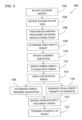
- FIG. 3 this illustrates an example of operation of a missile system according to an embodiment of the present invention, corresponding also to an implementation of a method according to the present invention, generally designated 100, illustrating a selection of the features described above.
- the missile system receives a dataset sufficient to define a position of a target relative to the launching position and launching orientation of the missile, most preferably in terms of real-world coordinates and angles of the launcher and real-world coordinates of the target. Some of the data may be "received" from various devices integrated with launcher 38, as described above.
- the system also receives data sufficient to determine an ego-motion scaling factor, typically through determining a distance to an object corresponding to a pixel of the seeker image, or through determining a velocity of the missile after launch by measurement or calculation.
- the system From launch during flight of the missile, the system performs ego-motion processing on a plurality of image frames from the imaging sensor so as to derive a position of the missile (step 106), and derives a calculated target direction from a current position of the missile to the target (step 108).
- the calculated target direction is then used in one or more manner for the purpose of correcting a flight path of the missile to the target.
- the calculated target direction is used directly as a basis for the guidance subsystem for navigating the missile to the target (step 110).
- steps 106-110 may be performed throughout the flight of the missile to provide autonomous fire-and-forget functionality based only on ego-motion navigation.
- the system can receive inputs from the operator to update the target designation if necessary (step 120).
- the missile system then typically continues with terminal guidance towards the target (step 122), typically by applying tracking algorithms to a sequence of images from the imaging sensor to track a target, and steering the missile towards the target tracked by the tracking algorithms.
- electro-optic missiles which are currently either remotely manually controlled or which provide "fire, observe and update” functionality can typically be provided with navigation-based visual prompts and/or automatic guidance to a geographic target simply by modification of the remote controller station 48, without requiring any change to the hardware of the missile, and in most cases, without even modifying the software of the missile itself.
Landscapes
- Engineering & Computer Science (AREA)
- General Engineering & Computer Science (AREA)
- Chemical & Material Sciences (AREA)
- Combustion & Propulsion (AREA)
- Radar, Positioning & Navigation (AREA)
- Remote Sensing (AREA)
- Physics & Mathematics (AREA)
- Aviation & Aerospace Engineering (AREA)
- General Physics & Mathematics (AREA)
- Automation & Control Theory (AREA)
- Electromagnetism (AREA)
- Aiming, Guidance, Guns With A Light Source, Armor, Camouflage, And Targets (AREA)
Claims (12)
- Système de missile comprenant :(a) un missile (10) ;(b) une tête chercheuse (14) située au niveau d'une partie nez dudit missile, ladite tête chercheuse comprenant un capteur d'imagerie électro-optique (16) ;(c) un dispositif de commande destiné à diriger le missile le long d'une trajectoire de vol vers une cible, ledit dispositif de commande comprenant :(i) un sous-système de poursuite (22) recevant des images dudit capteur d'imagerie, ledit système de poursuite étant configuré pour poursuivre une cible dans lesdites images et pour déterminer une direction de la cible poursuivie ; et(ii) un sous-système de guidage (24) utilisable pour diriger le missile vers la cible poursuivie, à l'aide d'un algorithme de guidage sur la base de ladite direction de la cible poursuivie ; et(d) un sous-système de navigation (26a, 26b) recevant des images dudit capteur d'imagerie,caractérisé en ce que ledit capteur d'imagerie électro-optique (16) de ladite tête chercheuse est un capteur d'image monté sur cardan, à champ de vision étroit, NFOV, ayant un angle de vision de moins de 15 degrés, et soutenu par un dispositif de cardan (18) de manière à être mobile par rapport à un corps (12) dudit missile (10),et caractérisé en outre en ce que ledit sous-système de navigation est configuré pour :(i) traiter conjointement une pluralité desdites images provenant dudit capteur d'imagerie monté sur cardan NFOV pour trouver un mouvement propre dudit missile par rapport à une zone observée par ledit capteur d'imagerie monté sur cardan NFOV en suivant le mouvement apparent d'éléments stationnaires apparaissant dans une pluralité de vues provenant de différents emplacements et en déduisant le mouvement dudit capteur d'imagerie monté sur cardan NFOV par rapport aux éléments suivis ;(ii) déduire dudit mouvement propre une direction calculée de cible dudit missile vers une cible ; et(iii) fournir ladite direction calculée de cible audit sous-système de guidage (24) pendant au moins une partie d'un vol dudit missile en tant que remplacement de ladite direction de cible poursuivie pour utilisation dans l'algorithme de guidage.
- Système de missile selon la revendication 1, dans lequel le sous-système de navigation (26a, 26b) est en outre configuré pour aligner une direction actuelle de cible poursuivie dudit sous-système de poursuite avec ladite direction calculée de cible pendant au moins une partie d'un vol dudit missile.
- Système de missile selon l'une quelconque des revendications précédentes, dans lequel ledit sous-système de navigation (26a, 26b) est en outre configuré pour amener ledit sous-système de poursuite (22) à effectuer une rechercher automatisée au sein d'une zone autour de ladite direction calculée de cible pour acquérir une cible poursuivie.
- Système de missile selon l'une quelconque des revendications précédentes, dans lequel ledit sous-système de navigation (26a, 26b) est en outre configuré pour :(a) déterminer à partir dudit mouvement propre une distance-objet correspondant à une distance allant du missile à un objet apparaissant dans une image provenant dudit capteur d'imagerie monté sur cardan NFOV le long de la direction-vers-cible ;(b) déterminer une distance-cible correspondant à une distance allant d'une position actuelle du missile à la cible ; et(c) comparer ladite distance-objet à ladite distance-cible pour déterminer si la cible est cachée.
- Système de missile selon l'une quelconque des revendications précédentes, comprenant en outre un poste d'opérateur (48) à distance, incluant un afficheur (50) un dispositif d'entrée (52) opérateur et des composants d'un sous-système de communication (54) destiné à communiquer avec des composants d'un sous-système de communication (34) à l'intérieur dudit missile (10), ledit poste d'opérateur à distance recevant et affichant des images provenant dudit capteur d'imagerie monté sur cardan NFOV (16), et recevant des entrées de commande via ledit dispositif d'entrée (52) opérateur pour modifier le fonctionnement dudit missile.
- Système de missile selon la revendication 5, dans lequel ledit sous-système de navigation (26a, 26b) est configuré pour engendrer un message visuel pour affichage sur ledit afficheur (50), ledit message visuel étant déduit de ladite direction calculée de cible, pour faciliter l'identification d'une cible par l'opérateur.
- Système de missile selon la revendication 5, dans lequel ledit sous-système de navigation (26a, 26b) est configuré en outre pour engendrer une limite d'une zone d'incertitude autour d'une position de la cible pour affichage sur ledit afficheur.
- Système de missile selon l'une quelconque des revendications précédentes, dans lequel ledit sous-système de navigation (26a, 26b) comprend en outre un dispositif de mémorisation de données destiné à mémoriser, avant le lancement dudit missile, des données correspondant à :(a) des coordonnées d'une position géographique du missile ;(b) des angles d'orientation du missile ; et(c) des coordonnées d'une position de la cible.
- Système de missile selon la revendication 8, dans lequel ledit dispositif de mémorisation de données mémorise en outre des données correspondant à une portée jusqu'à un emplacement correspondant à un pixel au sein d'une image échantillonnée par ledit capteur d'imagerie monté sur cardan NFOV avant le lancement.
- Système de missile selon l'une quelconque des revendications précédentes, ledit missile étant configuré pour être opérationnel sans un système de navigation inertielle embarqué et sans capteurs de signaux de positionnement par satellite embarqués.
- Procédé d'utilisation du système de missile selon l'une quelconque des revendications précédentes, le procédé comprenant les étapes consistant à :(a) recevoir un ensemble de données suffisant pour définir une position d'une cible par rapport à la position de lancement et l'orientation de lancement du missile, et des données suffisantes pour déterminer un facteur d'échelle pour déduction de mouvement propre basée sur le suivi du mouvement apparent d'éléments stationnaires apparaissant dans la pluralité de vues depuis différents emplacements ;(b) à partir du lancement, pendant le vol du missile, effectuer un traitement de mouvement propre sur une pluralité d'images individuelles provenant du capteur d'imagerie monté sur cardan NFOV de manière à trouver une position du missile en suivant le mouvement apparent d'éléments stationnaires apparaissant dans la pluralité de vues depuis différents emplacements et en déduisant, en utilisant le facteur d'échelle, le mouvement dudit capteur d'imagerie monté sur cardan NFOV par rapport aux éléments suivis ; et(c) déduire une direction calculée de cible d'une position actuelle du missile vers la cible.
- Procédé selon la revendication 11, comprenant en outre :(a) pendant une première partie d'un vol du missile, diriger le missile sur la base de ladite direction calculée de cible ; et(b) pendant une seconde partie du vol du missile :(i) appliquer des algorithmes de poursuite à une séquence d'images provenant du capteur d'imagerie monté sur cardan NFOV pour poursuivre une cible ; et(ii) diriger le missile vers la cible poursuivie par lesdits algorithmes de poursuite.
Applications Claiming Priority (2)
| Application Number | Priority Date | Filing Date | Title |
|---|---|---|---|
| IL227982A IL227982B (en) | 2013-08-15 | 2013-08-15 | Missile system with navigation capability based on image processing |
| PCT/IL2014/050540 WO2015022681A1 (fr) | 2013-08-15 | 2014-06-15 | Système de missile à capacité de navigation basée sur un traitement d'images |
Publications (4)
| Publication Number | Publication Date |
|---|---|
| EP3033584A1 EP3033584A1 (fr) | 2016-06-22 |
| EP3033584A4 EP3033584A4 (fr) | 2017-04-12 |
| EP3033584B1 true EP3033584B1 (fr) | 2025-03-12 |
| EP3033584C0 EP3033584C0 (fr) | 2025-03-12 |
Family
ID=49784256
Family Applications (1)
| Application Number | Title | Priority Date | Filing Date |
|---|---|---|---|
| EP14835900.3A Active EP3033584B1 (fr) | 2013-08-15 | 2014-06-15 | Système de missile à capacité de navigation basée sur un traitement d'images |
Country Status (5)
| Country | Link |
|---|---|
| US (1) | US10078339B2 (fr) |
| EP (1) | EP3033584B1 (fr) |
| ES (1) | ES3018470T3 (fr) |
| IL (1) | IL227982B (fr) |
| WO (1) | WO2015022681A1 (fr) |
Families Citing this family (13)
| Publication number | Priority date | Publication date | Assignee | Title |
|---|---|---|---|---|
| US20170307334A1 (en) * | 2016-04-26 | 2017-10-26 | Martin William Greenwood | Apparatus and System to Counter Drones Using a Shoulder-Launched Aerodynamically Guided Missile |
| EP3513302B1 (fr) * | 2016-10-07 | 2020-07-01 | Google LLC | Identification et affichage de trajets lisses et délimités |
| US10121091B2 (en) | 2017-02-09 | 2018-11-06 | Rosemount Aerospace Inc. | IMU-aided image registration |
| US10809064B2 (en) | 2018-02-08 | 2020-10-20 | Raytheon Company | Image geo-registration for absolute navigation aiding using uncertainy information from the on-board navigation system |
| US10877489B2 (en) * | 2018-03-26 | 2020-12-29 | Simmonds Precision Products, Inc. | Imaging seeker for a spin-stabilized projectile |
| KR102136759B1 (ko) * | 2019-04-03 | 2020-07-22 | 엘아이지넥스원 주식회사 | 유도비행체의 정렬 상태 측정장치, 방법 및 이를 이용한 정렬 상태 측정시스템 |
| US11371806B2 (en) | 2019-08-05 | 2022-06-28 | Bae Systems Information And Electronic Systems Integration Inc. | Midbody camera/sensor navigation and automatic target recognition |
| CN114442654B (zh) * | 2020-11-03 | 2023-10-27 | 北京理工大学 | 卫星图像复合制导方法 |
| CN114820701B (zh) * | 2022-04-12 | 2025-04-08 | 彩虹无人机科技有限公司 | 一种基于多模板的红外成像导引头捕获跟踪目标方法 |
| US12592156B2 (en) * | 2022-05-04 | 2026-03-31 | California Institute Of Technology | Method and system for on-board localization |
| IL296458A (en) * | 2022-09-13 | 2024-12-01 | Rafael Advanced Defense Systems Ltd | Electro-optical tactical missile system |
| KR102546814B1 (ko) * | 2022-11-28 | 2023-06-23 | 국방과학연구소 | 유도탄의 지형 간섭 판단방법 및 이를 위한 판단장치 |
| DE102023000398A1 (de) * | 2023-02-09 | 2024-08-14 | Diehl Defence Gmbh & Co. Kg | Verfahren zum Betrieb eines Lenkflugkörpers an einer Startplattform |
Family Cites Families (19)
| Publication number | Priority date | Publication date | Assignee | Title |
|---|---|---|---|---|
| US3564134A (en) * | 1968-07-03 | 1971-02-16 | Us Navy | Two-camera remote drone control |
| US4396903A (en) * | 1981-05-29 | 1983-08-02 | Westinghouse Electric Corp. | Electro-optical system for correlating and integrating image data from frame-to-frame |
| GB2293067B (en) * | 1984-06-29 | 1996-07-10 | Marconi Avionics | Processor arrangement |
| NO164137C (no) * | 1984-07-10 | 1990-08-29 | Norges Teknisk Naturvitenskape | System for deteksjon av objekter for gitte, kjente katarkteristika, mot en bakgrunn. |
| DE3843006A1 (de) * | 1988-12-21 | 1990-06-28 | Messerschmitt Boelkow Blohm | Vorrichtung fuer das auffinden und die identifizierung von einzelzielen |
| FR2657160B1 (fr) * | 1990-01-12 | 1992-05-07 | Aerospatiale | Systeme embarque pour determiner la position d'un vehicule aerien et ses applications. |
| US5260709A (en) * | 1991-12-19 | 1993-11-09 | Hughes Aircraft Company | Autonomous precision weapon delivery using synthetic array radar |
| DE4218600C2 (de) | 1992-06-05 | 1994-09-22 | Bodenseewerk Geraetetech | Einrichtung zur Bestimmung von Bewegungsgrößen eines Flugkörpers |
| US5323987A (en) | 1993-03-04 | 1994-06-28 | The Boeing Company | Missile seeker system and method |
| US5627905A (en) * | 1994-12-12 | 1997-05-06 | Lockheed Martin Tactical Defense Systems | Optical flow detection system |
| US5660355A (en) * | 1996-05-23 | 1997-08-26 | Hughes Missile Systems Company | Angle only range estimator for homing missile |
| JP4116116B2 (ja) | 1997-09-11 | 2008-07-09 | 富士重工業株式会社 | 移動体の測距原点認識装置 |
| FR2830078B1 (fr) * | 2001-09-25 | 2004-01-30 | Sagem | Procede de guidage d'une roquette |
| US8666661B2 (en) | 2006-03-31 | 2014-03-04 | The Boeing Company | Video navigation |
| WO2008024772A1 (fr) | 2006-08-21 | 2008-02-28 | University Of Florida Research Foundation, Inc. | Système et procédés de guidage et de navigation pour véhicule utilisant des images |
| DE102007054950B4 (de) * | 2007-11-17 | 2013-05-02 | Mbda Deutschland Gmbh | Verfahren zur Stützung der selbsttätigen Navigation eines niedrig fliegenden Flugkörpers |
| US9127908B2 (en) * | 2009-02-02 | 2015-09-08 | Aero Vironment, Inc. | Multimode unmanned aerial vehicle |
| DE102009042172A1 (de) * | 2009-09-18 | 2011-04-21 | Lfk-Lenkflugkörpersysteme Gmbh | Verfahren zur Bereitstellung von Steuerbefehlen für ein mittels einer Bedieneinheit lenkbares Fahrzeug und Steuerungssystem für ein derartiges lenkbares Fahr zeug |
| US8447116B2 (en) * | 2011-07-22 | 2013-05-21 | Honeywell International Inc. | Identifying true feature matches for vision based navigation |
-
2013
- 2013-08-15 IL IL227982A patent/IL227982B/en active IP Right Grant
-
2014
- 2014-06-15 EP EP14835900.3A patent/EP3033584B1/fr active Active
- 2014-06-15 WO PCT/IL2014/050540 patent/WO2015022681A1/fr not_active Ceased
- 2014-06-15 ES ES14835900T patent/ES3018470T3/es active Active
- 2014-06-15 US US14/911,469 patent/US10078339B2/en active Active
Also Published As
| Publication number | Publication date |
|---|---|
| WO2015022681A1 (fr) | 2015-02-19 |
| US20160195878A1 (en) | 2016-07-07 |
| IL227982A0 (en) | 2013-12-31 |
| EP3033584C0 (fr) | 2025-03-12 |
| EP3033584A4 (fr) | 2017-04-12 |
| EP3033584A1 (fr) | 2016-06-22 |
| IL227982B (en) | 2018-11-29 |
| ES3018470T3 (es) | 2025-05-16 |
| US10078339B2 (en) | 2018-09-18 |
Similar Documents
| Publication | Publication Date | Title |
|---|---|---|
| EP3033584B1 (fr) | Système de missile à capacité de navigation basée sur un traitement d'images | |
| AU2020204166B2 (en) | Interactive weapon targeting system displaying remote sensed image of target area | |
| US8525088B1 (en) | View-point guided weapon system and target designation method | |
| US8229163B2 (en) | 4D GIS based virtual reality for moving target prediction | |
| US8946606B1 (en) | Determining angular rate for line-of-sight to a moving object, with a body-fixed imaging sensor | |
| US8686326B1 (en) | Optical-flow techniques for improved terminal homing and control | |
| KR102853492B1 (ko) | 타겟을 여러 다른 디바이스에서 동시에 추적할 수 있도록 네트워크로 연결된 스코프가 있는 차량 탑재 장치 | |
| CA3064640C (fr) | Systeme et procede pour l`augmentation de la navigation | |
| JPH1185284A (ja) | 監視装置 | |
| CN119845267A (zh) | 一种可预测航迹的无卫星导航无人机位置估计方法 | |
| WO2024057102A1 (fr) | Système de missile tactique électro-optique |
Legal Events
| Date | Code | Title | Description |
|---|---|---|---|
| PUAI | Public reference made under article 153(3) epc to a published international application that has entered the european phase |
Free format text: ORIGINAL CODE: 0009012 |
|
| 17P | Request for examination filed |
Effective date: 20160209 |
|
| AK | Designated contracting states |
Kind code of ref document: A1 Designated state(s): AL AT BE BG CH CY CZ DE DK EE ES FI FR GB GR HR HU IE IS IT LI LT LU LV MC MK MT NL NO PL PT RO RS SE SI SK SM TR |
|
| AX | Request for extension of the european patent |
Extension state: BA ME |
|
| DAX | Request for extension of the european patent (deleted) | ||
| A4 | Supplementary search report drawn up and despatched |
Effective date: 20170310 |
|
| RIC1 | Information provided on ipc code assigned before grant |
Ipc: F41G 7/00 20060101ALI20170306BHEP Ipc: F41G 7/30 20060101ALI20170306BHEP Ipc: F41G 7/34 20060101ALI20170306BHEP Ipc: F42B 15/01 20060101AFI20170306BHEP Ipc: G01S 5/16 20060101ALI20170306BHEP Ipc: G05D 1/00 20060101ALI20170306BHEP |
|
| STAA | Information on the status of an ep patent application or granted ep patent |
Free format text: STATUS: EXAMINATION IS IN PROGRESS |
|
| 17Q | First examination report despatched |
Effective date: 20190711 |
|
| GRAP | Despatch of communication of intention to grant a patent |
Free format text: ORIGINAL CODE: EPIDOSNIGR1 |
|
| STAA | Information on the status of an ep patent application or granted ep patent |
Free format text: STATUS: GRANT OF PATENT IS INTENDED |
|
| RIC1 | Information provided on ipc code assigned before grant |
Ipc: F41G 7/34 20060101ALI20241023BHEP Ipc: F41G 7/22 20060101ALI20241023BHEP Ipc: G01C 21/12 20060101ALI20241023BHEP Ipc: G05D 1/00 20060101ALI20241023BHEP Ipc: F41G 7/00 20060101ALI20241023BHEP Ipc: F41G 7/30 20060101ALI20241023BHEP Ipc: G01S 5/16 20060101ALI20241023BHEP Ipc: F42B 15/01 20060101AFI20241023BHEP |
|
| INTG | Intention to grant announced |
Effective date: 20241118 |
|
| GRAS | Grant fee paid |
Free format text: ORIGINAL CODE: EPIDOSNIGR3 |
|
| GRAA | (expected) grant |
Free format text: ORIGINAL CODE: 0009210 |
|
| STAA | Information on the status of an ep patent application or granted ep patent |
Free format text: STATUS: THE PATENT HAS BEEN GRANTED |
|
| AK | Designated contracting states |
Kind code of ref document: B1 Designated state(s): AL AT BE BG CH CY CZ DE DK EE ES FI FR GB GR HR HU IE IS IT LI LT LU LV MC MK MT NL NO PL PT RO RS SE SI SK SM TR |
|
| REG | Reference to a national code |
Ref country code: GB Ref legal event code: FG4D |
|
| REG | Reference to a national code |
Ref country code: CH Ref legal event code: EP |
|
| REG | Reference to a national code |
Ref country code: DE Ref legal event code: R096 Ref document number: 602014091676 Country of ref document: DE |
|
| REG | Reference to a national code |
Ref country code: IE Ref legal event code: FG4D |
|
| U01 | Request for unitary effect filed |
Effective date: 20250408 |
|
| U07 | Unitary effect registered |
Designated state(s): AT BE BG DE DK EE FI FR IT LT LU LV MT NL PT RO SE SI Effective date: 20250414 |
|
| REG | Reference to a national code |
Ref country code: ES Ref legal event code: FG2A Ref document number: 3018470 Country of ref document: ES Kind code of ref document: T3 Effective date: 20250516 |
|
| U20 | Renewal fee for the european patent with unitary effect paid |
Year of fee payment: 12 Effective date: 20250522 |
|
| PG25 | Lapsed in a contracting state [announced via postgrant information from national office to epo] |
Ref country code: RS Free format text: LAPSE BECAUSE OF FAILURE TO SUBMIT A TRANSLATION OF THE DESCRIPTION OR TO PAY THE FEE WITHIN THE PRESCRIBED TIME-LIMIT Effective date: 20250612 |
|
| PGFP | Annual fee paid to national office [announced via postgrant information from national office to epo] |
Ref country code: GB Payment date: 20250619 Year of fee payment: 12 |
|
| PG25 | Lapsed in a contracting state [announced via postgrant information from national office to epo] |
Ref country code: NO Free format text: LAPSE BECAUSE OF FAILURE TO SUBMIT A TRANSLATION OF THE DESCRIPTION OR TO PAY THE FEE WITHIN THE PRESCRIBED TIME-LIMIT Effective date: 20250612 |
|
| PG25 | Lapsed in a contracting state [announced via postgrant information from national office to epo] |
Ref country code: HR Free format text: LAPSE BECAUSE OF FAILURE TO SUBMIT A TRANSLATION OF THE DESCRIPTION OR TO PAY THE FEE WITHIN THE PRESCRIBED TIME-LIMIT Effective date: 20250312 |
|
| PG25 | Lapsed in a contracting state [announced via postgrant information from national office to epo] |
Ref country code: GR Free format text: LAPSE BECAUSE OF FAILURE TO SUBMIT A TRANSLATION OF THE DESCRIPTION OR TO PAY THE FEE WITHIN THE PRESCRIBED TIME-LIMIT Effective date: 20250613 |
|
| PG25 | Lapsed in a contracting state [announced via postgrant information from national office to epo] |
Ref country code: SM Free format text: LAPSE BECAUSE OF FAILURE TO SUBMIT A TRANSLATION OF THE DESCRIPTION OR TO PAY THE FEE WITHIN THE PRESCRIBED TIME-LIMIT Effective date: 20250312 |
|
| PGFP | Annual fee paid to national office [announced via postgrant information from national office to epo] |
Ref country code: ES Payment date: 20250702 Year of fee payment: 12 |
|
| PG25 | Lapsed in a contracting state [announced via postgrant information from national office to epo] |
Ref country code: PL Free format text: LAPSE BECAUSE OF FAILURE TO SUBMIT A TRANSLATION OF THE DESCRIPTION OR TO PAY THE FEE WITHIN THE PRESCRIBED TIME-LIMIT Effective date: 20250312 |
|
| PG25 | Lapsed in a contracting state [announced via postgrant information from national office to epo] |
Ref country code: CZ Free format text: LAPSE BECAUSE OF FAILURE TO SUBMIT A TRANSLATION OF THE DESCRIPTION OR TO PAY THE FEE WITHIN THE PRESCRIBED TIME-LIMIT Effective date: 20250312 |
|
| PG25 | Lapsed in a contracting state [announced via postgrant information from national office to epo] |
Ref country code: SK Free format text: LAPSE BECAUSE OF FAILURE TO SUBMIT A TRANSLATION OF THE DESCRIPTION OR TO PAY THE FEE WITHIN THE PRESCRIBED TIME-LIMIT Effective date: 20250312 |
|
| PG25 | Lapsed in a contracting state [announced via postgrant information from national office to epo] |
Ref country code: IS Free format text: LAPSE BECAUSE OF FAILURE TO SUBMIT A TRANSLATION OF THE DESCRIPTION OR TO PAY THE FEE WITHIN THE PRESCRIBED TIME-LIMIT Effective date: 20250712 |
|
| PLBE | No opposition filed within time limit |
Free format text: ORIGINAL CODE: 0009261 |
|
| STAA | Information on the status of an ep patent application or granted ep patent |
Free format text: STATUS: NO OPPOSITION FILED WITHIN TIME LIMIT |
|
| REG | Reference to a national code |
Ref country code: CH Ref legal event code: L10 Free format text: ST27 STATUS EVENT CODE: U-0-0-L10-L00 (AS PROVIDED BY THE NATIONAL OFFICE) Effective date: 20260121 |
|
| REG | Reference to a national code |
Ref country code: CH Ref legal event code: H13 Free format text: ST27 STATUS EVENT CODE: U-0-0-H10-H13 (AS PROVIDED BY THE NATIONAL OFFICE) Effective date: 20260127 |
|
| PG25 | Lapsed in a contracting state [announced via postgrant information from national office to epo] |
Ref country code: MC Free format text: LAPSE BECAUSE OF FAILURE TO SUBMIT A TRANSLATION OF THE DESCRIPTION OR TO PAY THE FEE WITHIN THE PRESCRIBED TIME-LIMIT Effective date: 20250312 |
|
| 26N | No opposition filed |
Effective date: 20251215 |
|
| PG25 | Lapsed in a contracting state [announced via postgrant information from national office to epo] |
Ref country code: IE Free format text: LAPSE BECAUSE OF NON-PAYMENT OF DUE FEES Effective date: 20250615 |
|
| PG25 | Lapsed in a contracting state [announced via postgrant information from national office to epo] |
Ref country code: CH Free format text: LAPSE BECAUSE OF NON-PAYMENT OF DUE FEES Effective date: 20250630 |