EP3033668B1 - Verfahren zum bereitstellen einer bedienvorrichtung in einem fahrzeug und bedienvorrichtung - Google Patents
Verfahren zum bereitstellen einer bedienvorrichtung in einem fahrzeug und bedienvorrichtung Download PDFInfo
- Publication number
- EP3033668B1 EP3033668B1 EP14752291.6A EP14752291A EP3033668B1 EP 3033668 B1 EP3033668 B1 EP 3033668B1 EP 14752291 A EP14752291 A EP 14752291A EP 3033668 B1 EP3033668 B1 EP 3033668B1
- Authority
- EP
- European Patent Office
- Prior art keywords
- touch
- sensitive surface
- switching element
- display
- operating mode
- Prior art date
- Legal status (The legal status is an assumption and is not a legal conclusion. Google has not performed a legal analysis and makes no representation as to the accuracy of the status listed.)
- Active
Links
Images


Classifications
-
- G—PHYSICS
- G06—COMPUTING OR CALCULATING; COUNTING
- G06F—ELECTRIC DIGITAL DATA PROCESSING
- G06F3/00—Input arrangements for transferring data to be processed into a form capable of being handled by the computer; Output arrangements for transferring data from processing unit to output unit, e.g. interface arrangements
- G06F3/01—Input arrangements or combined input and output arrangements for interaction between user and computer
- G06F3/048—Interaction techniques based on graphical user interfaces [GUI]
- G06F3/0487—Interaction techniques based on graphical user interfaces [GUI] using specific features provided by the input device, e.g. functions controlled by the rotation of a mouse with dual sensing arrangements, or of the nature of the input device, e.g. tap gestures based on pressure sensed by a digitiser
- G06F3/0488—Interaction techniques based on graphical user interfaces [GUI] using specific features provided by the input device, e.g. functions controlled by the rotation of a mouse with dual sensing arrangements, or of the nature of the input device, e.g. tap gestures based on pressure sensed by a digitiser using a touch-screen or digitiser, e.g. input of commands through traced gestures
-
- B—PERFORMING OPERATIONS; TRANSPORTING
- B60—VEHICLES IN GENERAL
- B60K—ARRANGEMENT OR MOUNTING OF PROPULSION UNITS OR OF TRANSMISSIONS IN VEHICLES; ARRANGEMENT OR MOUNTING OF PLURAL DIVERSE PRIME-MOVERS IN VEHICLES; AUXILIARY DRIVES FOR VEHICLES; INSTRUMENTATION OR DASHBOARDS FOR VEHICLES; ARRANGEMENTS IN CONNECTION WITH COOLING, AIR INTAKE, GAS EXHAUST OR FUEL SUPPLY OF PROPULSION UNITS IN VEHICLES
- B60K35/00—Instruments specially adapted for vehicles; Arrangement of instruments in or on vehicles
- B60K35/80—Arrangements for controlling instruments
-
- B—PERFORMING OPERATIONS; TRANSPORTING
- B60—VEHICLES IN GENERAL
- B60K—ARRANGEMENT OR MOUNTING OF PROPULSION UNITS OR OF TRANSMISSIONS IN VEHICLES; ARRANGEMENT OR MOUNTING OF PLURAL DIVERSE PRIME-MOVERS IN VEHICLES; AUXILIARY DRIVES FOR VEHICLES; INSTRUMENTATION OR DASHBOARDS FOR VEHICLES; ARRANGEMENTS IN CONNECTION WITH COOLING, AIR INTAKE, GAS EXHAUST OR FUEL SUPPLY OF PROPULSION UNITS IN VEHICLES
- B60K35/00—Instruments specially adapted for vehicles; Arrangement of instruments in or on vehicles
- B60K35/10—Input arrangements, i.e. from user to vehicle, associated with vehicle functions or specially adapted therefor
-
- B—PERFORMING OPERATIONS; TRANSPORTING
- B60—VEHICLES IN GENERAL
- B60K—ARRANGEMENT OR MOUNTING OF PROPULSION UNITS OR OF TRANSMISSIONS IN VEHICLES; ARRANGEMENT OR MOUNTING OF PLURAL DIVERSE PRIME-MOVERS IN VEHICLES; AUXILIARY DRIVES FOR VEHICLES; INSTRUMENTATION OR DASHBOARDS FOR VEHICLES; ARRANGEMENTS IN CONNECTION WITH COOLING, AIR INTAKE, GAS EXHAUST OR FUEL SUPPLY OF PROPULSION UNITS IN VEHICLES
- B60K35/00—Instruments specially adapted for vehicles; Arrangement of instruments in or on vehicles
- B60K35/50—Instruments characterised by their means of attachment to or integration in the vehicle
-
- G—PHYSICS
- G06—COMPUTING OR CALCULATING; COUNTING
- G06F—ELECTRIC DIGITAL DATA PROCESSING
- G06F3/00—Input arrangements for transferring data to be processed into a form capable of being handled by the computer; Output arrangements for transferring data from processing unit to output unit, e.g. interface arrangements
- G06F3/01—Input arrangements or combined input and output arrangements for interaction between user and computer
- G06F3/048—Interaction techniques based on graphical user interfaces [GUI]
- G06F3/0484—Interaction techniques based on graphical user interfaces [GUI] for the control of specific functions or operations, e.g. selecting or manipulating an object, an image or a displayed text element, setting a parameter value or selecting a range
- G06F3/04842—Selection of displayed objects or displayed text elements
-
- B—PERFORMING OPERATIONS; TRANSPORTING
- B60—VEHICLES IN GENERAL
- B60K—ARRANGEMENT OR MOUNTING OF PROPULSION UNITS OR OF TRANSMISSIONS IN VEHICLES; ARRANGEMENT OR MOUNTING OF PLURAL DIVERSE PRIME-MOVERS IN VEHICLES; AUXILIARY DRIVES FOR VEHICLES; INSTRUMENTATION OR DASHBOARDS FOR VEHICLES; ARRANGEMENTS IN CONNECTION WITH COOLING, AIR INTAKE, GAS EXHAUST OR FUEL SUPPLY OF PROPULSION UNITS IN VEHICLES
- B60K2360/00—Indexing scheme associated with groups B60K35/00 or B60K37/00 relating to details of instruments or dashboards
- B60K2360/141—Activation of instrument input devices by approaching fingers or pens
-
- B—PERFORMING OPERATIONS; TRANSPORTING
- B60—VEHICLES IN GENERAL
- B60K—ARRANGEMENT OR MOUNTING OF PROPULSION UNITS OR OF TRANSMISSIONS IN VEHICLES; ARRANGEMENT OR MOUNTING OF PLURAL DIVERSE PRIME-MOVERS IN VEHICLES; AUXILIARY DRIVES FOR VEHICLES; INSTRUMENTATION OR DASHBOARDS FOR VEHICLES; ARRANGEMENTS IN CONNECTION WITH COOLING, AIR INTAKE, GAS EXHAUST OR FUEL SUPPLY OF PROPULSION UNITS IN VEHICLES
- B60K2360/00—Indexing scheme associated with groups B60K35/00 or B60K37/00 relating to details of instruments or dashboards
- B60K2360/143—Touch sensitive instrument input devices
- B60K2360/1438—Touch screens
-
- B—PERFORMING OPERATIONS; TRANSPORTING
- B60—VEHICLES IN GENERAL
- B60K—ARRANGEMENT OR MOUNTING OF PROPULSION UNITS OR OF TRANSMISSIONS IN VEHICLES; ARRANGEMENT OR MOUNTING OF PLURAL DIVERSE PRIME-MOVERS IN VEHICLES; AUXILIARY DRIVES FOR VEHICLES; INSTRUMENTATION OR DASHBOARDS FOR VEHICLES; ARRANGEMENTS IN CONNECTION WITH COOLING, AIR INTAKE, GAS EXHAUST OR FUEL SUPPLY OF PROPULSION UNITS IN VEHICLES
- B60K2360/00—Indexing scheme associated with groups B60K35/00 or B60K37/00 relating to details of instruments or dashboards
- B60K2360/55—Remote control arrangements
- B60K2360/56—Remote control arrangements using mobile devices
- B60K2360/573—Mobile devices controlling vehicle functions
Definitions
- the present invention relates to a method for providing an operating device in a vehicle.
- the operating device comprises a mobile device that is located in the interior of the vehicle.
- the mobile device has a display surface on which a touch-sensitive surface is formed. It therefore has a so-called touchscreen.
- graphic data are generated which are displayed on the display surface of the mobile device.
- An approach of an actuation object to the touch-sensitive surface is also detected. If it has been detected that an actuating object has approached the touch-sensitive surface, the representation on the display area changes from a display mode to an operating mode, with at least one actuatable switching element being displayed in the operating mode.
- the invention also relates to an operating device in a vehicle.
- the operating device comprises a mobile device that is located in the interior of the vehicle, the mobile device having a display surface on which a touch-sensitive surface is formed.
- the operating device further comprises a control device which is coupled to the mobile device or is integrated into the mobile device.
- the control device can be used to generate graphic data that can be displayed on the display surface of the mobile device.
- the operating device further comprises a proximity detection device for detecting an actuation object that is approaching the touch-sensitive surface.
- Mobile devices such as so-called smartphones, are becoming more and more powerful. At the same time, the spread of such devices is increasing. It is therefore possible to couple mobile devices with devices of the vehicle and to integrate them into the operating device of the vehicle.
- the disadvantage of using conventional mobile devices in a vehicle is that the operation of these devices is not designed for use by the driver of a vehicle while driving.
- the touchscreen of such mobile devices is often relatively small and the operating concept is not tailored to the fact that the operation requires as little attention as necessary from the user.
- the operating process in the vehicle should also be able to be carried out quickly, easily and intuitively by the driver of the vehicle while driving.
- a display and control device in a motor vehicle is known.
- the display device is operated in a display mode and in an operating mode with a control unit.
- an actuation element such as a user's finger
- this is detected and switched from the display mode to the operating mode.
- a multifunction display and operating device which comprises a touch screen. This device also switches from a display mode to an operating mode when an actuating object approaches this touchscreen,
- WO 2013/053466 A2 a method for providing an operating device is known in which a change is made from a display state to an operating state when an actuation object has been detected in a detection area in front of a display surface.
- EP 1 886 865 A1 discloses a touchscreen-based graphic operating system built into a motor vehicle, in which no operating elements are visible on the touchscreen during the playback of multimedia content. These are only displayed after the detection of an approach of an operating element and the knowledge derived therefrom, a likely imminent operating interaction. Furthermore, switching to a full-screen media playback mode is disclosed solely by approaching the touchscreen.
- the present invention is based on the object of providing a method and an operating device of the type mentioned at the beginning, which enable fast, intuitive and simple operation of the touch-sensitive surface of the mobile device even when the detection of the approach of the actuating object to the touch-sensitive surface does not work or works incorrectly.
- the method according to the invention is characterized in that the representation on the display area also changes from the display mode to the operating mode when it has been detected that the actuation object is touching the touch-sensitive surface.
- a switching element is understood to mean a control element of a graphical user interface in the operating mode.
- a switching element differs from elements and areas for pure information display, so-called display elements, in that they can be selected and an indication of the function of the switching element is displayed differently than in the display mode.
- display elements When a switching element is selected, a function assigned to it is carried out. The function can only lead to a change in the information display.
- devices can be controlled via the switching elements, the operation of which is supported by the information display.
- the switching elements can thus replace conventional mechanical switches.
- the switching elements can be generated and displayed by any freely programmable display area.
- the actuation object which is used in the method according to the invention can be, for example, the fingertip of a user, an actuation pen or any other object.
- the method according to the invention provides a fallback solution for such cases. Actuations on the touch-sensitive surface are possible even if the representation on the display surface of the mobile device is in display mode. In particular, touching the touch-sensitive surface leads at least to the fact that the representation on the display area changes from the display mode to the operating mode. In the display mode, entries can thus be made, regardless of whether the representation on the display area refers to switching elements or not.
- the switching element is defined in a partial area of the touch-sensitive surface. Furthermore, several switching elements can also be defined for the partial area.
- a control signal is generated. This control signal is assigned to the switched switching element and controls, for example, the function of a device in the vehicle.
- an indication of the function of the control signal is displayed in the operating mode on the partial area of the switching element. In the display mode, however, this reference to the function is not displayed.
- the control signal is also generated in the display mode.
- the proximity detection is not functional, the user can thus control the signal of a switching element, although the reference to the function of the control signal is not displayed. This is advantageous if the user already knows from previous operating processes that a certain partial area of the touch-sensitive surface can be actuated for a certain display.
- the representation on the display area also changes from the display mode to the operating mode, even if no approach of the actuating object to the touch-sensitive surface was previously detected. This ensures that when the following operations are carried out, corresponding information on the function of the control signals that are assigned to the switching elements is displayed.
- the display on the display area changes from the display mode to the operating mode, even if the actuation object has not previously approached the touch-sensitive surface was recorded. If the proximity detection fails, the user can thus manually generate a change from the display mode to the operating mode by touching the touch-sensitive surface of the mobile device. If he touches the touch-sensitive surface on the partial area in which a switching element is displayed in the operating mode, a change is made to the operating mode and at the same time the control signal for the corresponding switching element is generated.
- the control signal assigned to a switching element can only be generated if the touch of the actuating object on the touch-sensitive surface outside the sub-area of the switching element or the switching elements has been released again and then touching the touch-sensitive surface again on the sub-area of the switching element by the actuating object becomes. Since the display has switched to the operating mode after the first touch of the touch-sensitive surface, the user is again shown the information about the function of the control signal that is assigned to the switching element for the second touch of the touch-sensitive surface. This supports the user in actuating the switching element.
- the representation on the display area changes again from the operating mode to the display mode. This ensures that the representation on the display surface does not remain in the operating mode for an unnecessarily long time, in particular when the proximity detection has a malfunction and removal of the actuation object from the touch-sensitive surface has not been detected.
- the operating device is characterized in that the control device is designed in such a way that the representation on the display area changes from a display mode to an operating mode when it has been detected that the operating object has approached the touch-sensitive surface, switching elements that can be operated in the operating mode being displayed , and the representation on the display area also changes from the display mode to the operating mode when it has been detected that the actuation object is touching the touch-sensitive surface.
- the operating device according to the invention is designed in particular to carry out the method according to the invention. It thus also has the same advantages as the method according to the invention.
- the control device is an application that can be executed on the mobile device. This means that it is not necessary to have to adapt a control device provided in the vehicle to different models of the mobile device.
- An application adapted to the device, which the control device provides, runs on the mobile device.
- the operating device has, in particular, a holder for releasably attaching the mobile device.
- the proximity detection device is arranged at the holder, so that an approach of the actuation object to the touch-sensitive surface of the mobile device can be detected when the mobile device is attached to the holder.
- a possible proximity detection device of the mobile device is not used, but an proximity detection device integrated in the vehicle.
- the approach of an actuation object to the touch-sensitive surface of the mobile device can be detected more reliably.
- the actuation of the touch-sensitive surface of the mobile device is also possible if such an approach is erroneously not detected.
- the proximity detection device is in particular integrated into the holder. In this way, the approach to the touch-sensitive surface of the mobile device can be detected as reliably as possible.
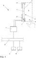
- the operating device 6 comprises a mobile device 1 which is detachably fastened by means of a holder 17 in the interior of the vehicle 12 in such a way that the display surface 2 of the mobile device 1 is clearly visible to at least one vehicle occupant, in particular the driver.
- the display surface 2 can be provided by a display, in particular a liquid crystal display, of any type.
- a touch-sensitive surface 4 is formed on the display surface 2 of the mobile device 1. A so-called touch screen is thus provided.
- the mobile device 1 can be, for example, a smartphone or a mobile navigation device.
- the operating device 6 further comprises a control device 3 which is coupled to the mobile device 1.
- a bidirectional data exchange between the mobile device 1 and the control device 3 is possible via this coupling.
- the coupling can take place via a radio interface or, as in Figure 1 shown, via a mechanical / electrical connection of the mobile device 1 to an interface of the holder 17 and a cable connection to the control device 3.
- the control device 3 is integrated in the vehicle 12 in this case.
- control device 3 is part of the mobile device 1.
- the control device 3 can be an application that can be executed on the mobile device 1. This application can be started automatically, for example, when the mobile device 1 is attached to the holder 17.
- the function of the control device 3 can also be provided jointly by a control device on the vehicle and on the mobile device.
- the operating device 6 comprises an approach detection device 7.
- This approach detection device 7 is integrated in the holder 17. It can be used to detect an actuation object 11, such as the fingertip 11 of a user, in a detection area 8 in front of the touch-sensitive surface 4 of the mobile device 1. As soon as the actuating object 11 enters the detection area 8, this is detected by the proximity detection device 7 and a corresponding signal is transmitted to the control device 3.
- the proximity detection device 7 is coupled to the control device 3 via a data connection.
- the proximity detection device 7 detects when the actuation object 11 is no longer located in the detection space 8. In this case too, a corresponding signal is transmitted to the control device 3.
- proximity detection devices 7 are known per se. Further details can be found in the WO 2011/051361 A1 can be removed.
- control device 3 is coupled to a data bus 5 of the vehicle 12.
- the control device 3 is connected via this data bus 5 to further devices 9, 10 of the vehicle 12, about which information is to be displayed on the display area 2 and which is to be operated by means of the operating device 6.
- Information about the devices 9, 10 of the vehicle 12 can thus be displayed to the vehicle occupants by means of the mobile device 1 of the operating device 6.
- the vehicle occupants can control and operate the devices 9, 10 by means of the mobile device 1.
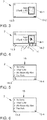
- FIGS Figures 3 to 9 On the display surface 2 of the mobile device 1, for example, the in Figure 3 The representation shown is reproduced.
- the information displayed belongs to a music playback device of the mobile device 1 or of the vehicle 12.
- the display elements 13-1 to 13-3 are shown.
- the proximity detection device 7 transmits a corresponding signal to the control device 3, which forwards this signal to the mobile device 1.
- the mobile device 1 could also be coupled directly to the proximity detection device 7.
- the mobile device 1 or the control device 3 displays the display on the display area 2 as in FIG Figure 4 Changed shown:
- the display elements 13-1 to 13-3 are converted into so-called switching elements 14-1 to 14-3, in which an indication of the function that is assigned to the respective switching element is displayed.
- the display of the display element 13-1 changes, for example, in such a way that a triangular symbol in the associated switch element 14-1 indicates that the user can change the title of the album being played when this switch element 14-1 is actuated.
- the display elements 13-1 and 13-3 change so that the associated symbols are shown enlarged, as is the case with the switching elements 14-2 and 14-3 of Figure 4 is shown.
- This enlargement of the representation indicates to the user that the partial areas which are located on the touch-sensitive surface 4 in these switching elements 14 - 2 and 14 - 3 can be actuated by touching them with the fingertip 11.
- the switching element 14-1 indicates to the user that he can touch the touch-sensitive surface 4 in this partial area in order to actuate the switching element 14-1.
- the representation on the display area 2 thus changes from a display mode as shown in FIG Figure 3 is shown in an operating mode as shown in Figure 4 is shown when it has been detected by the proximity detection device 7 that an actuation object 11, such as the fingertip 11 of a user, has approached the touch-sensitive surface 4. The approach is detected from the point in time at which the actuating object 11 has entered the detection space 8.
- actuatable switching elements 14-1 to 14-3 are then displayed.
- the control device 3 or the mobile device 1 As soon as the user has touched the switching element 14 - 1 after the actuation object 11 has entered the detection space 8, this is detected by the control device 3 or the mobile device 1. A control signal assigned to the switching element 14-1 is then generated and the representation on the display area 2 changes to that in FIG Figure 5 shown display. The display is still in the operating mode, a list 15 with the titles of the album being displayed. Furthermore, the switching element 14-3 can still be displayed. Instead of the switching element 14-2, the switching element 14-4 for a voice input is displayed in this menu in the operating mode.
- the user can now select a specific title by touching the touch-sensitive surface 4 on the partial area in which the corresponding title is displayed. If there is no operation by the user for a certain time interval, the representation on the display area 2 automatically switches back to the display mode, as shown in FIG Figure 6 is shown.
- the list 15 is shown reduced in this case.
- the switching elements 14-3 and 14-4 are shown reduced as display elements 13-3 and 13-4.
- This type of method in which the representation on the display surface 2 changes from a display mode to an operating mode when an actuation object 11 approaches the touch-sensitive surface 4, is known per se.
- the special feature of the method according to the invention is that a fallback solution is provided for the case in which the proximity detection device 7 has a malfunction. For example, the entry of the fingertip 11 into the detection space 8 is not detected by the proximity detection device 7. In the procedure described above, in this case there would be no change from the display mode to the operating mode and usually no actuation of the touch-sensitive surface 4 would be possible either.
- the representation on the display area 2 also changes from the display mode to the operating mode when it has been detected that an actuation object, such as the fingertip 11 of the user in the present case, is touching the touch-sensitive surface 4. This change from the display mode to the operating mode also takes place in particular if no approach of the fingertip 11 to the touch-sensitive surface 4 was previously detected.
- the control device 3 or the mobile device 1 directly generates a control signal that is assigned to the corresponding switching element 14-1. That is to say, in the present case, when this partial area of the touch-sensitive surface 4 is touched, the representation on the display area 2 changes to the one shown in FIG Figure 5 shown condition. At the same time, the representation on the display area 2 changes from the display mode to the operating mode.
- the display on the display area 2 changes from However, the display mode also changes to the operating mode when the user touches the touch-sensitive surface 4 outside of the partial areas that are assigned to a switching element in the operating mode. Via this indirect operation, the representation on the display area 2 changes from the display mode to the operating mode, however, without generating a control signal which is assigned to a switching element.
- the in Figure 9 displayed display in operating mode. If the user now releases the touch of the touch-sensitive surface 4 with his fingertip 11 again and then touches the switching element 14-1, for example, the control device 3 or the mobile device 1 generates a control signal which leads to a change in the display on the display surface 2, so that the in Figure 5 displayed display.
- the touch-sensitive surface 4 is thus divided into a sub-area in which the switching elements 14 are located in the operating mode, and another sub-area 16 in which there are no switching elements 14 in the operating mode.
- a control signal is additionally generated which is assigned to a switching element 14 of the operating mode.
- the proximity detection device 7 Even if the proximity detection device 7 fails, the user can thus continue to operate the mobile device 1 and use it to control the devices 9, 10 of the vehicle 12.
Landscapes
- Engineering & Computer Science (AREA)
- Chemical & Material Sciences (AREA)
- Combustion & Propulsion (AREA)
- Transportation (AREA)
- Mechanical Engineering (AREA)
- General Engineering & Computer Science (AREA)
- Theoretical Computer Science (AREA)
- Human Computer Interaction (AREA)
- Physics & Mathematics (AREA)
- General Physics & Mathematics (AREA)
- User Interface Of Digital Computer (AREA)
Description
- Die vorliegende Erfindung betrifft ein Verfahren zum Bereitstellen einer Bedienvorrichtung in einem Fahrzeug. Die Bedienvorrichtung umfasst ein mobiles Gerät, das sich im Innenraum des Fahrzeugs befindet. Das mobile Gerät weist eine Anzeigefläche auf, auf der eine berührungsempfindliche Oberfläche ausgebildet ist. Es besitzt somit einen sogenannten Touchscreen. Bei dem Verfahren werden Graphikdaten erzeugt, die auf der Anzeigefläche des mobilen Geräts angezeigt werden. Ferner wird eine Annäherung eines Betätigungsobjekts an die berührungsempfindliche Oberfläche erfasst. Wenn erfasst wurde, dass sich ein Betätigungsobjekt an die berührungsempfindliche Oberfläche angenähert hat, wechselt die Darstellung auf der Anzeigefläche von einem Anzeigemodus in einen Bedienmodus, wobei im Bedienmodus zumindest ein betätigbares Schaltelement angezeigt wird. Die Erfindung betrifft des Weiteren eine Bedienvorrichtung in einem Fahrzeug. Die Bedienvorrichtung umfasst ein mobiles Gerät, das sich im Innenraum des Fahrzeugs befindet, wobei das mobile Gerät eine Anzeigefläche aufweist, auf der eine berührungsempfindliche Oberfläche ausgebildet ist. Die Bedienvorrichtung umfasst ferner eine Steuervorrichtung, die mit dem mobilen Gerät gekoppelt ist oder in das mobile Gerät integriert ist. Mit der Steuervorrichtung sind Graphikdaten erzeugbar, die auf der Anzeigefläche des mobilen Geräts anzeigbar sind. Die Bedienvorrichtung umfasst des Weiteren eine Annäherungserfassungseinrichtung zum Erfassen eines Betätigungsobjekts, das sich an die berührungsempfindliche Oberfläche annähert.
- Mobile Geräte, wie beispielsweise sogenannte Smartphones, werden immer leistungsfähiger. Gleichzeitig steigt die Verbreitung solcher Geräte. Es besteht daher die Möglichkeit, mobile Geräte mit Einrichtungen des Fahrzeugs zu koppeln und sie in die Bedienvorrichtung des Fahrzeugs zu integrieren. Nachteilig an der Verwendung von herkömmlichen mobilen Geräten in einem Fahrzeug ist, dass die Bedienung dieser Geräte nicht für eine Nutzung durch den Fahrer eines Fahrzeugs während der Fahrt ausgelegt ist. Der Touchscreen solcher mobiler Geräte ist vielfach relativ klein und das Bedienkonzept ist nicht darauf abgestimmt, dass die Bedienung vom Nutzer so wenig Aufmerksamkeit wie nötig erfordert.
- Beim Bereitstellen einer Bedienvorrichtung in einem Fahrzeug ist es jedoch wichtig, dass die Bedienvorgänge nicht zu einer Ablenkung des Fahrers während der Fahrt führt. Der Bedienvorgang im Fahrzeug sollte schnell, einfach und intuitiv auch vom Fahrer des Fahrzeugs während der Fahrt vorgenommen werden können.
- Aus der
EP 1 935 704 A1 ist eine Anzeige- und Bedienvorrichtung in einem Kraftfahrzeug bekannt. Bei dieser Vorrichtung wird mit einer Steuereinheit die Anzeigevorrichtung in einem Anzeigemodus und in einem Bedienmodus betrieben. Wenn ein Betätigungselement, wie beispielsweise der Finger eines Nutzers, sich an die Anzeigefläche annähert, wird dies erfasst und von dem Anzeigemodus in den Bedienmodus umgeschaltet. - Aus der
DE 10 2007 023 290 A1 ist eine Multifunktionsanzeige- und Bedienvorrichtung bekannt, die einen Touchscreen umfasst. Auch bei dieser Vorrichtung wird von einem Anzeigemodus in einen Bedienmodus umgeschaltet, wenn sich ein Betätigungsobjekt an diesen Touchscreen annähert, - Ferner ist aus der
WO 2013/053466 A2 ein Verfahren zum Bereitstellen einer Bedienvorrichtung bekannt, bei dem von einem Anzeigezustand in einen Bedienzustand gewechselt wird, wenn ein Betätigungsobjekt in einem Detektionsbereich vor einer Anzeigefläche erfasst wurde. -
EP 1 886 865 A1 offenbart ein in ein KFZ eingebautes, touchscreenbasiertes grafisches Bediensystem, bei dem während der Wiedergabe von Multimediainhalten keine Bedienelemente auf dem Touchscreen sichtbar sind. Diese werden erst nach der Erkennung einer Annäherung eines Bedienelementes und der daraus abgeleiteten Erkenntnis, einer voraussichtlich bevorstehenden Bedieninteraktion, eingeblendet. Des Weiteren wird ein Umschalten in einen Vollbildmedienwiedergabenmodus allein durch eine Annäherung an den Touchscreen offenbart. - Der vorliegenden Erfindung liegt die Aufgabe zugrunde, ein Verfahren und eine Bedienvorrichtung der eingangs genannten Art bereitzustellen, welche eine schnelle, intuitive und einfache Bedienung der berührungsempfindlichen Oberfläche des mobilen Geräts auch dann ermöglichen, wenn das Erfassen der Annäherung des Betätigungsobjekts an die berührungsempfindliche Oberfläche nicht funktioniert oder fehlerhaft funktioniert.
- Diese Aufgabe wird erfindungsgemäß durch ein Verfahren mit den Merkmalen des Anspruchs 1 und ein Bedienvorrichtung mit den Merkmalen des Anspruchs 3 gelöst. Vorteilhafte Ausgestaltungen und Weiterbildungen ergeben sich aus den abhängigen Ansprüchen.
- Das erfindungsgemäße Verfahren ist dadurch gekennzeichnet, dass die Darstellung auf der Anzeigefläche auch dann von dem Anzeigemodus in den Bedienmodus wechselt, wenn erfasst wurde, dass das Betätigungsobjekt die berührungsempfindliche Oberfläche berührt.
- Unter einem Schaltelement wird im Sinne der Erfindung ein Steuerelement einer graphischen Benutzerschnittstelle in dem Bedienmodus verstanden. Ein Schaltelement unterscheidet sich von Elementen und Flächen zur reinen Informationsanzeige, so genannten Anzeigeelementen, darin, dass sie auswählbar sind und ein Hinweis auf die Funktion des Schaltelements anders als im Anzeigemodus angezeigt wird. Bei einer Auswahl eines Schaltelements wird eine ihr zugeordnete Funktion ausgeführt. Die Funktion kann nur zu einer Veränderung der Informationsanzeige führen. Ferner können über die Schaltelemente Einrichtungen gesteuert werden, deren Bedienung von der Informationsanzeige unterstützt wird. Die Schaltelemente können somit herkömmliche mechanische Schalter ersetzen. Die Schaltelemente können beliebig für eine frei programmierbaren Anzeigefläche erzeugt und von dieser angezeigt werden.
- Bei dem Betätigungsobjekt, welches bei dem erfindungsgemäßen Verfahren verwendet wird, kann es sich beispielsweise um die Fingerspitze eines Nutzers, einen Betätigungsstift oder irgendein anderes Objekt handeln.
- Bei herkömmlichen Verfahren, welche einen Anzeigemodus und einen Bedienmodus bei der Darstellung auf einer Anzeigefläche mit einer berührungsempfindlichen Oberfläche verwenden, sind im Anzeigemodus keine Bedienvorgänge ausführbar. Eine Betätigung der berührungsempfindlichen Oberfläche ist nur im Bedienmodus möglich. Bei einer Annäherung eines Betätigungsobjekts an die berührungsempfindliche Oberfläche wechselt die Darstellungsart jedoch automatisch in den Bedienmodus, so dass es normalerweise für den Nutzer unbeachtlich ist, dass im Anzeigemodus keine Betätigung möglich ist.
- Bei der Verwendung eines mobilen Geräts in dem Fahrzeug ergibt sich jedoch das Problem, dass die Annäherung des Betätigungsobjekts an die berührungsempfindliche Oberfläche des mobilen Geräts möglicherweise nicht sicher erkannt wird. Das erfindungsgemäße Verfahren stellt für solche Fälle eine Rückfalllösung bereit. Selbst wenn sich die Darstellung auf der Anzeigefläche des mobilen Geräts im Anzeigemodus befindet, sind Betätigungen auf der berührungsempfindlichen Oberfläche möglich. Insbesondere führt die Berührung der berührungsempfindlichen Oberfläche zumindest dazu, dass die Darstellung auf der Anzeigefläche von dem Anzeigemodus in den Bedienmodus wechselt. Im Anzeigemodus können somit Eingaben vorgenommen werden, unabhängig davon, ob die Darstellung auf der Anzeigefläche auf Schaltelemente hinweist oder nicht.
- Gemäß einer Ausgestaltung des erfindungsgemäßen Verfahrens ist das Schaltelement bei einer Teilfläche der berührungsempfindlichen Oberfläche definiert. Ferner können bei der Teilfläche auch mehrere Schaltelemente definiert sein. Bei einer Berührung dieser Teilfläche des Schaltelements oder bei der Berührung eines der Schaltelemente wird ein Steuersignal erzeugt. Dieses Steuersignal ist dem berührten Schaltelement zugeordnet und steuert beispielsweise die Funktion einer Einrichtung des Fahrzeugs. Bei dieser Ausgestaltung des erfindungsgemäßen Verfahrens wird im Bedienmodus bei der Teilfläche des Schaltelements ein Hinweis auf die Funktion des Steuersignals angezeigt. Im Anzeigemodus wird dieser Hinweis auf die Funktion hingegen nicht angezeigt. Bei der Berührung der Teilfläche des Schaltelements wird das Steuersignal jedoch auch im Anzeigemodus erzeugt. Auch wenn die Annäherungserfassung nicht funktionsfähig ist, kann der Nutzer somit das Steuersignal eines Schaltelements erzeugen, obwohl der Hinweis auf die Funktion des Steuersignals nicht angezeigt wird. Dies ist dann vorteilhaft, wenn der Nutzer bereits aus früheren Bedienvorgängen weiß, dass bei einer bestimmten Anzeige eine bestimmte Teilfläche der berührungsempfindlichen Oberfläche betätigbar ist.
- In diesem Fall wechselt bei der Berührung der Teilfläche, bei der im Bedienmodus das Schaltelement oder eines der Schaltelemente angezeigt wird, ferner die Darstellung auf der Anzeigefläche von dem Anzeigemodus in den Bedienmodus, selbst wenn vorher keine Annäherung des Betätigungsobjekts an die berührungsempfindliche Oberfläche erfasst wurde. Hierdurch wird erreicht, dass bei den folgenden Betätigungen wieder entsprechende Hinweise auf die Funktion der Steuersignale angezeigt werden, die den Schaltelementen zugeordnet sind.
- Gemäß dem erfindungsgemäßen Verfahren wechselt bei einer Berührung der berührungsempfindlichen Oberfläche außerhalb der Teilfläche, bei der im Bedienmodus das Schaltelement oder die Schaltelemente dargestellt werden, die Darstellung auf der Anzeigefläche von dem Anzeigemodus in den Bedienmodus, selbst wenn vorher keine Annäherung des Betätigungsobjekts an die berührungsempfindliche Oberfläche erfasst wurde. Der Nutzer kann somit bei einem Ausfall der Annäherungserfassung eine Wechsel von dem Anzeigemodus in den Bedienmodus manuell erzeugen, indem er die berührungsempfindliche Oberfläche des mobilen Geräts berührt. Wenn er die berührungsempfindliche Oberfläche bei der Teilfläche berührt, bei der im Bedienmodus ein Schaltelement dargestellt wird, erfolgt ein Wechsel in den Bedienmodus und gleichzeitig wird das Steuersignal für das entsprechende Schaltelement erzeugt.
- Wenn der Nutzer hingegen die berührungsempfindliche Oberfläche außerhalb der Teilfläche, bei der im Bedienmodus eines der Schaltelemente dargestellt wird berührt, erfolgt nur ein Wechsel in den Bedienmodus, ohne dass das Steuersignal erzeugt wird. Das einem Schaltelement zugeordnete Steuersignal kann in diesem Fall insbesondere nur dann erzeugt werden, wenn die Berührung des Betätigungsobjekts bei der berührungsempfindlichen Oberfläche außerhalb der Teilfläche des Schaltelements oder der Schaltelemente wieder gelöst wurde und danach die berührungsempfindliche Oberfläche wieder bei der Teilfläche des Schaltelements von dem Betätigungsobjekt berührt wird. Da nach der ersten Berührung der berührungsempfindlichen Oberfläche die Darstellung in den Bedienmodus gewechselt hat, wird dem Nutzer für die zweite Berührung der berührungsempfindlichen Oberfläche wieder der Hinweis auf die Funktion des Steuersignals angezeigt, welches dem Schaltelement zugeordnet ist. Hierdurch wird der Nutzer bei der Betätigung des Schaltelements unterstützt.
- Wenn im Bedienmodus für ein vordefiniertes Zeitintervall keine Eingaben auf der berührungsempfindlichen Oberfläche erfasst worden sind, wechselt die Darstellung auf der Anzeigefläche wieder von dem Bedienmodus in den Anzeigemodus. Hierdurch wird erreicht, dass die Darstellung auf der Anzeigefläche nicht unnötig lange im Bedienmodus verbleibt, insbesondere dann, wenn die Annäherungserfassung eine Fehlfunktion hat und ein Entfernen des Betätigungsobjekts von der berührungsempfindlichen Oberfläche nicht erfasst worden ist.
- Die erfindungsgemäße Bedienvorrichtung ist dadurch gekennzeichnet, dass die Steuervorrichtung so ausgebildet ist, dass die Darstellung auf der Anzeigefläche von einem Anzeigemodus in einen Bedienmodus wechselt, wenn erfasst wurde, dass sich das Betätigungsobjekt an die berührungsempfindliche Oberfläche angenähert hat, wobei im Bedienmodus betätigbare Schaltelemente angezeigt werden, und die Darstellung auf der Anzeigefläche auch dann von dem Anzeigemodus in den Bedienmodus wechselt, wenn erfasst wurde, dass das Betätigungsobjekt die berührungsempfindliche Oberfläche berührt.
- Die erfindungsgemäße Bedienvorrichtung ist insbesondere ausgebildet, das erfindungsgemäße Verfahren auszuführen. Sie weist somit auch dieselben Vorteile wie das erfindungsgemäße Verfahren auf.
- Gemäß einer Ausgestaltung der erfindungsgemäßen Bedienvorrichtung ist die Steuervorrichtung eine auf dem mobilen Gerät ausführbare Anwendung. Hierdurch wird erreicht, dass es nicht erforderlich ist, eine in dem Fahrzeug vorgesehene Steuervorrichtung an verschiedene Modelle des mobilen Geräts anpassen zu müssen. Auf dem mobilen Gerät läuft jeweils eine an das Gerät angepasste Anwendung, welche die Steuervorrichtung bereitstellt.
- Die Bedienvorrichtung weist insbesondere eine Halterung zum lösbaren Befestigen des mobilen Geräts auf. Die Annäherungserfassungseinrichtung ist in diesem Fall bei der Halterung angeordnet, so dass eine Annäherung des Betätigungsobjekts an die berührungsempfindliche Oberfläche des mobilen Geräts erfassbar ist, wenn das mobile Gerät an der Halterung befestigt ist. Vorteilhafterweise wird somit nicht eine etwaige Annäherungserfassungseinrichtung des mobilen Geräts genutzt, sondern eine in das Fahrzeug integrierte Annäherungserfassungseinrichtung. Hierdurch kann die Annäherung eines Betätigungsobjekts an die berührungsempfindliche Oberfläche des mobilen Geräts verlässlicher erfasst werden. Allerdings ist die Betätigung der berührungsempfindlichen Oberfläche des mobilen Geräts, wie vorstehend erläutert, auch dann möglich, wenn eine solche Annäherung fehlerhafterweise nicht erfasst wird.
- Die Annäherungserfassungseinrichtung ist insbesondere in die Halterung integriert. Auf diese Weise kann die Annäherung an die berührungsempfindliche Oberfläche des mobilen Geräts so verlässlich wie möglich erfasst werden.
- Die Erfindung wird nun anhand eines Ausführungsbeispiels mit Bezug zu den Zeichnungen erläutert.
- Figur 1
- zeigt schematisch ein Ausführungsbeispiel der erfindungsgemäßen Bedienvorrichtung und die Verbindung dieser Bedienvorrichtung mit anderen Einrichtungen des Fahrzeugs,
- Figur 2
- zeigt ein Fahrzeug mit dem Ausführungsbeispiel der erfindungsgemäßen Bedienvorrichtung und
- Figuren 3 bis 9
- zeigen Anzeigen auf der Anzeigefläche des mobilen Geräts, welche von einem Ausführungsbeispiel des erfindungsgemäßen Verfahrens erzeugt werden.
- Mit Bezug zu den
Figuren 1 und2 wird zunächst ein Ausführungsbeispiel der erfindungsgemäßen Bedienvorrichtung 6 und deren Anordnung in einem Fahrzeug 12 erläutert:
Die Bedienvorrichtung 6 umfasst ein mobiles Gerät 1, welches mittels einer Halterung 17 so im Innenraum des Fahrzeugs 12 lösbar befestigt ist, dass die Anzeigefläche 2 des mobilen Geräts 1 zumindest für einen Fahrzeuginsassen, insbesondere für den Fahrer, gut sichtbar ist. Die Anzeigefläche 2 kann von einem Display, insbesondere einem Flüssigkristalldisplay, beliebiger Bauart bereitgestellt werden. Auf der Anzeigefläche 2 des mobilen Geräts 1 ist eine berührungsempfindliche Oberfläche 4 ausgebildet. Es wird somit ein sogenannter Touchscreen bereitgestellt. Bei dem mobilen Gerät 1 kann es sich beispielsweise um ein Smartphone oder eine mobile Navigationsvorrichtung handeln. - Die Bedienvorrichtung 6 umfasst ferner eine Steuervorrichtung 3, die mit dem mobilen Gerät 1 gekoppelt ist. Über diese Kopplung ist ein bidirektionaler Datenaustausch zwischen dem mobilen Gerät 1 und der Steuervorrichtung 3 möglich. Die Kopplung kann über eine Funkschnittstelle erfolgen oder, wie in
Figur 1 gezeigt, über einen mechanisch/elektrischen Anschluss des mobilen Geräts 1 an eine Schnittstelle der Halterung 17 und eine Kabelverbindung zu der Steuervorrichtung 3. Die Steuervorrichtung 3 ist in diesem Fall in das Fahrzeug 12 integriert. - Bei einem anderen Ausführungsbeispiel ist die Steuervorrichtung 3 Teil des mobilen Geräts 1. Beispielsweise kann die Steuervorrichtung 3 eine auf dem mobilen Gerät 1 ausführbare Anwendung sein. Diese Anwendung kann beispielsweise automatisch gestartet werden, wenn das mobile Gerät 1 an der Halterung 17 befestigt wird. Schließlich kann die Funktion der Steuervorrichtung 3 auch gemeinsam von einer fahrzeugseitigen und mobilgeräteseitigen Steuervorrichtung bereitgestellt werden.
- Des Weiteren umfasst die Bedienvorrichtung 6 eine Annäherungserfassungseinrichtung 7. Diese Annäherungserfassungseinrichtung 7 ist in die Halterung 17 integriert. Mittels ihr kann ein Betätigungsobjekt 11, wie beispielsweise die Fingerspitze 11 eines Nutzers, in einem Detektionsbereich 8 vor der berührungsempfindlichen Oberfläche 4 des mobilen Geräts 1 erfasst werden. Sobald das Betätigungsobjekt 11 in den Detektionsbereich 8 eintritt, wird dies von der Annäherungserfassungseinrichtung 7 erfasst und ein entsprechendes Signal an die Steuervorrichtung 3 übertragen. Hierfür ist die Annäherungserfassungseinrichtung 7 über eine Datenverbindung mit der Steuervorrichtung 3 gekoppelt. Außerdem erfasst die Annäherungserfassungseinrichtung 7, wenn das Betätigungsobjekt 11 sich nicht mehr in dem Detektionsraum 8 befindet. Auch in diesem Fall wird ein entsprechendes Signal an die Steuervorrichtung 3 übertragen.
- Derartige Annäherungserfassungseinrichtungen 7 sind an sich bekannt. Weitere Details können beispielsweise der
WO 2011/051361 A1 entnommen werden. - Schließlich ist die Steuervorrichtung 3 mit einem Datenbus 5 des Fahrzeugs 12 gekoppelt. Über diesen Datenbus 5 ist die Steuervorrichtung 3 mit weiteren Einrichtungen 9, 10 des Fahrzeugs 12 verbunden, zu denen Informationen auf der Anzeigefläche 2 angezeigt werden sollen und die mittels der Bedienvorrichtung 6 bedient werden sollen. Mittels des mobilen Geräts 1 der Bedienvorrichtung 6 können den Fahrzeuginsassen somit Informationen zu den Einrichtungen 9, 10 des Fahrzeugs 12 angezeigt werden. Ferner können die Fahrzeuginsassen mittels dem mobilen Gerät 1 die Einrichtungen 9, 10 steuern und bedienen.
- Im Folgenden werden weitere Details der Ausgestaltung der Steuervorrichtung 3 in Verbindung mit einem Ausführungsbeispiel des erfindungsgemäßen Verfahrens mit Bezug zu den
Figuren 3 bis 9 erläutert:
Auf der Anzeigefläche 2 des mobilen Geräts 1 wird beispielsweise die inFigur 3 gezeigte Darstellung wiedergegeben. Die angezeigten Informationen gehören zu einer Musikwiedergabeeinrichtung des mobilen Geräts 1 oder des Fahrzeugs 12. Es werden insbesondere die Anzeigeelemente 13-1 bis 13-3 dargestellt. - Wenn der Nutzer nun die Musikwiedergabeeinrichtung bedienen will, nähert er sich mit seiner Fingerspitze 11 der berührungsempfindlichen Oberfläche 4 auf der Anzeigefläche 2 an, wie es in
Figur 4 gezeigt ist. Sobald die Fingerspitze 11 des Nutzers in den Detektionsraum 8 eingetreten ist, überträgt die Annäherungserfassungseinrichtung 7 ein entsprechendes Signal an die Steuervorrichtung 3, welche dieses Signal an das mobile Gerät 1 weitergibt. Alternativ könnte das mobile Gerät 1 auch direkt mit der Annäherungserfassungseinrichtung 7 gekoppelt sein. Daraufhin wird von dem mobilen Gerät 1 oder der Steuervorrichtung 3 die Darstellung auf der Anzeigefläche 2 wie inFigur 4 gezeigt geändert: Die Anzeigeelemente 13-1 bis 13-3 wandeln sich in sogenannte Schaltelemente 14-1 bis 14-3 um, bei denen ein Hinweis auf die Funktion, die dem jeweiligen Schaltelement zugeordnet ist, angezeigt wird. Die Darstellung des Anzeigeelements 13-1 ändert sich zum Beispiel derart, dass im zugehörigen Schaltelement 14-1 durch ein dreieckiges Symbol angezeigt wird, dass der Nutzer bei Betätigung dieses Schaltelements 14-1 den Titel des gespielten Albums ändern kann. Die Anzeigeelemente 13-1 und 13-3 ändern sich so, dass die zugeordneten Symbole vergrößert dargestellt werden, wie es bei den Schaltelementen 14-2 und 14-3 derFigur 4 gezeigt ist. Diese Vergrößerung der Darstellung weist den Nutzer darauf hin, dass die Teilflächen, welche sich bei der berührungsempfindlichen Oberfläche 4 bei diesen Schaltelementen 14-2 und 14-3 befinden, betätigbar sind, indem sie mit der Fingerspitze 11 berührt werden. Gleichermaßen weist das Schaltelement 14-1 den Nutzer darauf hin, dass er die berührungsempfindliche Oberfläche 4 bei diesem Teilbereich berühren kann, um das Schaltelement 14-1 zu betätigen. - Die Darstellung auf der Anzeigefläche 2 wechselt somit von einem Anzeigemodus, wie er in
Figur 3 gezeigt ist, in einen Bedienmodus, wie er inFigur 4 gezeigt ist, wenn von der Annäherungserfassungseinrichtung 7 erfasst wurde, dass sich ein Betätigungsobjekt 11, wie beispielsweise die Fingerspitze 11 eines Nutzers, an die berührungsempfindliche Oberfläche 4 angenähert hat. Die Annäherung wird ab dem Zeitpunkt erfasst, zu dem das Betätigungsobjekt 11 in den Detektionsraum 8 eingetreten ist. Im Bedienmodus werden dann betätigbare Schaltelemente 14-1 bis 14-3 angezeigt. - Sobald nach dem Eintritt des Betätigungsobjekts 11 in den Detektionsraum 8 der Nutzer das Schaltelement 14-1 berührt hat, wird dies von der Steuervorrichtung 3 bzw. dem mobilen Gerät 1 erfasst. Daraufhin wird ein dem Schaltelement 14-1 zugeordnetes Steuersignal erzeugt und die Darstellung auf der Anzeigefläche 2 wechselt in die in
Figur 5 gezeigte Anzeige. Die Darstellung befindet sich weiterhin im Bedienmodus, wobei eine Liste 15 mit den Titeln des Albums angezeigt wird. Ferner kann weiterhin das Schaltelement 14-3 angezeigt werden. Statt des Schaltelements 14-2 wird bei diesem Menü im Bedienmodus das Schaltelement 14-4 für eine Spracheingabe angezeigt. - Der Nutzer kann nun einen bestimmten Titel auswählen, indem er die berührungsempfindliche Oberfläche 4 bei der Teilfläche berührt, bei welcher der entsprechende Titel angezeigt wird. Wenn für ein bestimmtes Zeitintervall keine Bedienung durch den Nutzer erfolgt, wechselt die Darstellung auf der Anzeigefläche 2 automatisch wieder zurück in den Anzeigemodus, wie es in
Figur 6 gezeigt ist. Die Liste 15 wird in diesem Fall verkleinert dargestellt. Ferner werden die Schaltelemente 14-3 und 14-4 verkleinert als Anzeigeelemente 13-3 und 13-4 dargestellt. - Diese Art des Verfahrens, bei welcher die Darstellung auf der Anzeigefläche 2 von einem Anzeigemodus in einen Bedienmodus wechselt, wenn sich ein Betätigungsobjekt 11 an die berührungsempfindliche Oberfläche 4 annähert, ist an sich bekannt. Die Besonderheit des erfindungsgemäßen Verfahrens liegt nun darin, dass eine Rückfalllösung für den Fall bereitgestellt wird, in dem die Annäherungserfassungseinrichtung 7 eine Fehlfunktion aufweist. Beispielsweise wird der Eintritt der Fingerspitze 11 in den Detektionsraum 8 nicht von der Annäherungserfassungseinrichtung 7 erfasst. Bei der vorstehend beschriebenen Verfahrensführung, würde in diesem Fall kein Wechsel von dem Anzeigemodus in den Bedienmodus erfolgen und üblicherweise wäre auch keine Betätigung der berührungsempfindlichen Oberfläche 4 möglich.
- Bei dem erfindungsgemäßen Verfahren sind jedoch auch im Anzeigemodus Eingaben über die berührungsempfindliche Oberfläche 4 des mobilen Geräts 1 möglich. Außerdem wechselt die Darstellung auf der Anzeigefläche 2 auch dann von dem Anzeigemodus in den Bedienmodus, wenn erfasst wurde, dass ein Betätigungsobjekt, wie im vorliegenden Fall die Fingerspitze 11 des Nutzers, die berührungsempfindliche Oberfläche 4 berührt. Dieser Wechsel von dem Anzeigemodus in den Bedienmodus erfolgt insbesondere auch dann, wenn vorher keine Annäherung der Fingerspitze 11 an die berührungsempfindliche Oberfläche 4 erfasst wurde.
- Der Ablauf des Verfahrens bei einer Fehlfunktion der Annäherungserfassungseinrichtung 7 wird im Folgenden mit Bezug zu den
Figuren 3 bis 9 erläutert:
Wenn der Nutzer ausgehend von der Anzeige im Anzeigemodus gemäßFigur 3 sich mit seiner Fingerspitze 11 an die berührungsempfindliche Oberfläche 4 annähert und in den Detektionsraum 8 eintritt, erfolgt aufgrund der Fehlfunktion der Annäherungserfassungseinrichtung 7 kein Wechsel vom Anzeigemodus in den Bedienmodus. Die Darstellung verbleibt im Anzeigemodus, wie dies inFigur 7 gezeigt ist. Wenn der Nutzer nun aus früheren Bedienvorgängen weiß, dass sich bei dem Anzeigelement 13-1 im Bedienmodus ein Schaltelement befindet, kann er die Teilfläche der berührungsempfindlichen Oberfläche 4 bei dem Anzeigeelement 13-1 berühren. Diese Berührung wird auch im Anzeigemodus von dem mobilen Gerät 1 bzw. der Steuervorrichtung 3 erfasst und verarbeitet. Im Fall der direkten Bedienung einer Teilfläche der berührungsempfindlichen Oberfläche 4, die im Bedienmodus einem Schaltelement zugeordnet ist, erzeugt die Steuervorrichtung 3 oder das mobile Gerät 1 direkt ein Steuersignal, das dem entsprechenden Schaltelement 14-1 zugeordnet ist. Das heißt im vorliegenden Fall wechselt bei der Berührung dieser Teilfläche der berührungsempfindlichen Oberfläche 4 die Darstellung auf der Anzeigefläche 2 in den inFigur 5 gezeigten Zustand. Gleichzeitig wechselt die Darstellung auf der Anzeigefläche 2 von dem Anzeigemodus in den Bedienmodus. - Wenn der Nutzer nicht weiß, bei welchen Teilflächen der berührungsempfindlichen Oberfläche 4 sich im Bedienmodus Schaltelemente befinden, weil beispielsweise im Anzeigemodus kein Hinweis auf diese Teilfläche angezeigt wird oder weil der Nutzer entsprechende Bedienvorgängen bisher noch nicht ausgeführt hat, wechselt die Darstellung auf der Anzeigefläche 2 von dem Anzeigemodus in den Bedienmodus jedoch auch dann, wenn der Nutzer die berührungsempfindliche Oberfläche 4 außerhalb der Teilflächen berührt, die im Bedienmodus einem Schaltelement zugeordnet sind. Über diese indirekte Bedienung wechselt die Darstellung auf der Anzeigefläche 2 von dem Anzeigemodus in den Bedienmodus jedoch, ohne dass ein Steuersignal erzeugt wird, welches einem Schaltelement zugeordnet ist.
- Im Bedienmodus wird dann die in
Figur 9 wiedergegebene Anzeige im Bedienmodus dargestellt. Wenn der Nutzer nun die Berührung der berührungsempfindlichen Oberfläche 4 mit seiner Fingerspitze 11 wieder löst und anschließend beispielsweise das Schaltelement 14-1 berührt, erzeugt die Steuervorrichtung 3 oder das mobile Gerät 1 ein Steuersignal, welches zu einer Veränderung der Anzeige auf der Anzeigefläche 2 führt, so dass anschließend die inFigur 5 wiedergegebene Anzeige dargestellt wird. - Die berührungsempfindliche Oberfläche 4 ist somit in einen Teilbereich eingeteilt, bei denen sich im Bedienmodus die Schaltelemente 14 befinden, und einen anderen Teilbereich 16, bei denen sich im Bedienmodus keine Schaltelemente 14 befinden. Bei der Berührung beider Teilbereiche erfolgt ein Wechsel von dem Anzeigemodus in den Bedienmodus. Bei einer Berührung des Teilbereichs, bei dem sich im Bedienmodus die Schaltelemente 14 befinden, wird jedoch zusätzlich ein Steuersignal erzeugt, das einem Schaltelement 14 des Bedienmodus zugeordnet ist.
- Auch bei einem Ausfall der Annäherungserfassungseinrichtung 7 kann der Nutzer somit das mobile Gerät 1 weiterhin bedienen und darüber die Einrichtungen 9, 10 des Fahrzeugs 12 steuern.
-
- 1
- mobiles Gerät
- 2
- Anzeigefläche
- 3
- Steuervorrichtung
- 4
- berührungsempfindliche Oberfläche
- 5
- Datenbus
- 6
- Bedienvorrichtung
- 7
- Annäherungserfassungseinrichtung
- 8
- Detektionsraum
- 9
- Einrichtung des Fahrzeugs
- 10
- Einrichtung des Fahrzeugs
- 11
- Betätigungsobjekt; Fingerspitze des Nutzers
- 12
- Fahrzeug
- 13-1 bis 13-3
- Anzeigeelemente
- 14, 14-1 bis 14-4
- Schaltelemente
- 15
- Liste
- 16
- Bereich der berührungsempfindlichen Oberfläche außerhalb des Bereichs der Schaltelemente
- 17
- Halterung
Claims (6)
- Verfahren zum Bereitstellen einer Bedienvorrichtung (6) in einem Fahrzeug (12) zur Steuerung von Fahrzeugfunktionen, die ein mobiles Gerät (1) umfasst, das sich im Innenraum des Fahrzeugs (12) befindet, wobei das mobile Gerät (1) eine Anzeigefläche (2) aufweist, auf der eine berührungsempfindliche Oberfläche (4) ausgebildet ist, bei dem- Graphikdaten erzeugt werden, die auf der Anzeigefläche (2) des mobilen Geräts (1) angezeigt werden,- eine Annäherung eines Betätigungsobjekts (11) an die berührungsempfindliche Oberfläche (4) erfasst wird,- die Darstellung auf der Anzeigefläche (2) von einem Anzeigemodus in einen Bedienmodus wechselt, wenn erfasst wurde, dass sich ein Betätigungsobjekt (11) an die berührungsempfindliche Oberfläche (4) angenähert hat und bei einer Berührung eines angezeigten Schaltelements (14) ein diesem Schaltelement zugeordnetes Steuersignal erzeugt wird, und- für den Fall, dass durch eine Fehlfunktion nicht erfasst wurde, dass sich das Betätigungsobjekt (11) an die berührungsempfindliche Oberfläche (4) angenähert hat obwohl eine Annäherung des Betätigungsobjekts (11) an die berührungsempfindliche Oberfläche (4) erfolgt ist, die Darstellung auf der Anzeigefläche (2) während der Annäherung zunächst noch in dem Anzeigemodus erfolgt und dann aber von dem Anzeigemodus in den Bedienmodus wechselt, wenn erfasst wurde, dass das Betätigungsobjekt (11) die berührungsempfindliche Oberfläche (4) berührt, wobei im Bedienmodus bei der Teilfläche des Schaltelements (14) ein Hinweis auf die Funktion des Steuersignals angezeigt wird undbei Berührung einer Teilfläche der berührungsempfindlichen Oberfläche (4), in der sich im Bedienmodus ein Schaltelement (14) befindet, ein diesem Schaltelement zugeordnetes Steuersignal erzeugt wird, undbei Berührung einer Teilfläche der berührungsempfindlichen Oberfläche (4), in der sich im Bedienmodus kein Schaltelement (14) befindet, zunächst kein einem Schaltelement im Bedienmodus zugeordnetes Steuersignal erzeugt wird und erst bei anschließender erneuter Berührung der berührungsempfindlichen Oberfläche (4) im Bereich eines Schaltelements (14) ein diesem Schaltelement zugeordnetes Steuersignal erzeugt wird.
- Verfahren nach Anspruch 1 dadurch gekennzeichnet,
dass, wenn im Bedienmodus für ein vordefiniertes Zeitintervall keine Eingaben auf der berührungsempfindlichen Oberfläche (4) erfasst worden sind, die Darstellung auf der Anzeigefläche (2) von dem Bedienmodus in den Anzeigemodus wechselt. - Bedienvorrichtung (6) in einem Fahrzeug (12) zur Steuerung von Fahrzeugfunktionen, mit!- einem mobilen Gerät (1), das sich im Innenraum des Fahrzeugs (12) befindet, wobei das mobile Gerät (1) eine Anzeigefläche (2) aufweist, auf der eine berührungsempfindliche Oberfläche (4) ausgebildet ist,- einer Steuervorrichtung (3), die mit dem mobilen Gerät (1) gekoppelt ist oder in das mobile Gerät (1) integriert ist, mit der Graphikdaten erzeugbar sind, die auf der Anzeigefläche (2) des mobilen Geräts (1) anzeigbar sind,- einer Annäherungserfassungseinrichtung (7) zum Erfassen eines Betätigungsobjekts (11), das sich an die berührungsempfindliche Oberfläche (4) annähert,wobei die Steuervorrichtung (3) so ausgebildet ist, dass die Darstellung auf der Anzeigefläche (2) von dem Anzeigemodus in einen Bedienmodus wechselt, wenn erfasst wurde, dass sich das Betätigungsobjekt (11) an die berührungsempfindliche Oberfläche (4) angenähert hat, wobei im Bedienmodus betätigbare Schaltelemente (14) angezeigt werden, und bei einer Berührung eines angezeigten Schaltelements (14) ein diesem Schaltelement zugeordnetes Steuersignal erzeugt wird, und
für den Fall, dass durch eine Fehlfunktion nicht erfasst wurde, dass sich das Betätigungsobjekt (11) an die berührungsempfindliche Oberfläche (4) angenähert hat obwohl eine Annäherung des Betätigungsobjekts (11) an die berührungsempfindliche Oberfläche (4) erfolgt ist, die Darstellung auf der Anzeigefläche (2) während der Annäherung zunächst noch in dem Anzeigemodus erfolgt und dann aber von dem Anzeigemodus in den Bedienmodus wechselt, wenn erfasst wurde, dass das Betätigungsobjekt (11) die berührungsempfindliche Oberfläche (4) berührt, wobei im Bedienmodus bei der Teilfläche des Schaltelements (14) ein Hinweis auf die Funktion des Steuersignals angezeigt wird undbei Berührung einer Teilfläche der berührungsempfindlichen Oberfläche (4), in der sich im Bedienmodus ein Schaltelement (14) befindet, ein diesem Schaltelement zugeordnetes Steuersignal erzeugt wird, undbei Berührung einer Teilfläche der berührungsempfindlichen Oberfläche (4), in der sich im Bedienmodus kein Schaltelement (14) befindet, zunächst kein einem Schaltelement im Bedienmodus zugeordnetes Steuersignal erzeugt wird und erst bei anschließender erneuter Berührung der berührungsempfindlichen Oberfläche (4) im Bereich eines Schaltelements (14) ein diesem Schaltelement zugeordnetes Steuersignal erzeugt wird. - Bedienvorrichtung (6) nach Anspruch 3, dadurch gekennzeichnet,
dass die Steuervorrichtung (3) eine auf dem mobilen Gerät (1) ausführbare Anwendung ist. - Bedienvorrichtung (6) nach Anspruch 3 oder 4, dadurch gekennzeichnet,
dass die Bedienvorrichtung (6) eine Halterung (17) zum lösbaren Befestigen des mobilen Geräts (1) aufweist und dass die Annäherungserfassungseinrichtung (7) bei der Halterung (17) angeordnet ist, so dass eine Annäherung des Betätigungsobjekts (11) an die berührungsempfindliche Oberfläche (4) des mobilen Geräts (1) erfassbar ist, wenn das mobile Gerät (1) an der Halterung (17) befestigt ist. - Bedienvorrichtung (6) nach Anspruch 5, dadurch gekennzeichnet,
dass die Annäherungserfassungseinrichtung (7) in die Halterung (17) integriert ist.
Applications Claiming Priority (2)
| Application Number | Priority Date | Filing Date | Title |
|---|---|---|---|
| DE102013215904.8A DE102013215904A1 (de) | 2013-08-12 | 2013-08-12 | Verfahren zum Bereitstellen einer Bedienvorrichtung in einem Fahrzeug und Bedienvorrichtung |
| PCT/EP2014/067150 WO2015022286A1 (de) | 2013-08-12 | 2014-08-11 | Verfahren zum bereitstellen einer bedienvorrichtung in einem fahrzeug und bedienvorrichtung |
Publications (2)
| Publication Number | Publication Date |
|---|---|
| EP3033668A1 EP3033668A1 (de) | 2016-06-22 |
| EP3033668B1 true EP3033668B1 (de) | 2021-03-31 |
Family
ID=51355518
Family Applications (1)
| Application Number | Title | Priority Date | Filing Date |
|---|---|---|---|
| EP14752291.6A Active EP3033668B1 (de) | 2013-08-12 | 2014-08-11 | Verfahren zum bereitstellen einer bedienvorrichtung in einem fahrzeug und bedienvorrichtung |
Country Status (3)
| Country | Link |
|---|---|
| EP (1) | EP3033668B1 (de) |
| DE (1) | DE102013215904A1 (de) |
| WO (1) | WO2015022286A1 (de) |
Families Citing this family (3)
| Publication number | Priority date | Publication date | Assignee | Title |
|---|---|---|---|---|
| DE102017201236B4 (de) * | 2017-01-26 | 2023-09-07 | Volkswagen Aktiengesellschaft | Verfahren zum Betreiben eines Bediensystems, Bediensystem und Fahrzeug mit einem Bediensystem |
| DE102019204049A1 (de) * | 2019-03-25 | 2020-10-01 | Volkswagen Aktiengesellschaft | Vorrichtung und Verfahren zum Einstellen eines Parameterwerts in einem Fahrzeug |
| CN115048005B (zh) * | 2022-07-05 | 2024-05-28 | 武汉领普科技有限公司 | 智能开关控制方法和系统 |
Family Cites Families (8)
| Publication number | Priority date | Publication date | Assignee | Title |
|---|---|---|---|---|
| US7561145B2 (en) * | 2005-03-18 | 2009-07-14 | Microsoft Corporation | Systems, methods, and computer-readable media for invoking an electronic ink or handwriting interface |
| DE102006037762A1 (de) * | 2006-08-11 | 2008-02-28 | Volkswagen Ag | Multifunktionsbedienvorrichtung und Verfahren zum Betreiben einer Multifunktionsbedienvorrichtung |
| DE102007029618A1 (de) * | 2006-12-21 | 2008-06-26 | Volkswagen Ag | Berührungslos aktivierbare Anzeige- und Bedienvorrichtung |
| DE102006061778A1 (de) | 2006-12-21 | 2008-06-26 | Volkswagen Ag | Anzeige- und Bedienvorrichtung in einem Kraftfahrzeug mit von einer Position einer Bedienhand abhängig eingeblendeten Menüs |
| DE102007023290A1 (de) | 2007-05-16 | 2008-11-20 | Volkswagen Ag | Multifunktionsanzeige- und Bedienvorrichtung und Verfahren zum Betreiben einer Multifunktionsanzeige- und Bedienvorrichtung mit verbesserter Auswahlbedienung |
| DE102009051202A1 (de) | 2009-10-29 | 2011-05-12 | Volkswagen Ag | Verfahren zum Betreiben einer Bedienvorrichtung und Bedienvorrichtung |
| DE102011116120A1 (de) | 2011-10-15 | 2013-04-18 | Volkswagen Aktiengesellschaft | Verfahren zum Bereitstellen einer Bedienvorrichtung in einem Fahrzeug und Bedienvorrichtung für ein Fahrzeug |
| DE102011117289B4 (de) * | 2011-10-31 | 2017-08-24 | Volkswagen Ag | Verfahren zum Betreiben einer mobilen Vorrichtung in einem Fahrzeug, Koppelvorrichtung, Fahrzeug sowie System |
-
2013
- 2013-08-12 DE DE102013215904.8A patent/DE102013215904A1/de not_active Withdrawn
-
2014
- 2014-08-11 WO PCT/EP2014/067150 patent/WO2015022286A1/de not_active Ceased
- 2014-08-11 EP EP14752291.6A patent/EP3033668B1/de active Active
Non-Patent Citations (1)
| Title |
|---|
| None * |
Also Published As
| Publication number | Publication date |
|---|---|
| WO2015022286A1 (de) | 2015-02-19 |
| EP3033668A1 (de) | 2016-06-22 |
| DE102013215904A1 (de) | 2015-02-12 |
Similar Documents
| Publication | Publication Date | Title |
|---|---|---|
| EP2927791B1 (de) | Verfahren und vorrichtung zum bereitstellen einer graphischen benutzerschnittstelle in einem fahrzeug | |
| EP3096969B1 (de) | Anwenderschnittstelle und verfahren zum steuern einer lautstärke mittels einer berührungssensitiven anzeigeeinheit | |
| EP3063611A1 (de) | Vorrichtung und verfahren zum anpassen des inhaltes einer statusleiste | |
| EP3393843B1 (de) | Fahrzeug mit einer bilderfassungseinheit und einem bediensystem zum bedienen von einrichtungen des fahrzeugs sowie verfahren zum betreiben des bediensystems | |
| EP2425321B1 (de) | Verfahren und vorrichtung zum anzeigen von in listen geordneter information | |
| EP2924551B1 (de) | Verfahren und Vorrichtung zum Bereitstellen einer graphischen Benutzerschnittstelle in einem Fahrzeug | |
| EP2941685B1 (de) | Bedienverfahren und bediensystem in einem fahrzeug | |
| EP2246214B1 (de) | Verfahren und Vorrichtung zum Anzeigen von in Listen geordneter Information | |
| EP2930603B1 (de) | Verfahren und Vorrichtung zum Bereitstellen einer graphischen Benutzerschnittstelle in einem Fahrzeug | |
| EP3033668B1 (de) | Verfahren zum bereitstellen einer bedienvorrichtung in einem fahrzeug und bedienvorrichtung | |
| DE102009023897B4 (de) | Verfahren zum Bedienen einer Anzeigevorrichtung für betrachtungsseitenspezifische Informationsanzeigen und Bedienvorrichtung hierfür | |
| EP2925552B1 (de) | Bedienverfahren und bediensystem in einem strassenfahrzeug | |
| EP2917062B1 (de) | Verfahren zum anzeigen von informationen in einem fahrzeug und vorrichtung zum steuern der anzeige | |
| DE102015204978A1 (de) | Verfahren und Vorrichtung zum Betreiben eines Ausgabesystems mit einer Anzeigevorrichtung und zumindest einer weiteren Ausgabevorrichtung | |
| EP2766210B1 (de) | Verfahren zum bereitstellen einer bedienvorrichtung in einem fahrzeug und bedienvorrichtung | |
| EP2930050B1 (de) | Verfahren und Vorrichtung zum Anzeigen von Informationen in einem Fahrzeug | |
| EP2818353B1 (de) | Bedienvorrichtung in einem Fahrzeug und Verfahren zum Bedienen von Funktionseinrichtungen eines Fahrzeugs | |
| DE102016007921A1 (de) | Bedieneinrichtung für ein Funktionselement eines Kraftfahrzeugs und Verfahren zum Bedienen eines Funktionselements | |
| EP2703205B1 (de) | Verfahren zum Anzeigen und Bedienen von Funktionsgruppen und/oder Funktionen sowie eine Anzeige- und Bedienvorrichtung | |
| EP3143483B1 (de) | Bedienverfahren und bediensystem in einem fahrzeug | |
| DE102018202668A1 (de) | Bedienvorrichtung sowie Verfahren zum Ansteuern zumindest einer Funktionseinheit für ein Kraftfahrzeug mit einer optischen Verlagerung eines Bediensymbols | |
| DE102012016110B4 (de) | Verfahren zum Bereitstellen einer Bedienvorrichtung in einem Fahrzeug und Bedienvorrichtung hierfür | |
| DE102013019572A1 (de) | Verfahren zum Betreiben eines Infotainmentsystems eines Kraftwagens und Kraftwagen mit einem Infotainmentsystem | |
| EP2809541B1 (de) | Verfahren zum bereitstellen einer bedienvorrichtung in einem fahrzeug und bedienvorrichtung für ein fahrzeug | |
| DE102012022803A1 (de) | Bedienverfahren und Bediensystem in einem Straßenfahrzeug |
Legal Events
| Date | Code | Title | Description |
|---|---|---|---|
| PUAI | Public reference made under article 153(3) epc to a published international application that has entered the european phase |
Free format text: ORIGINAL CODE: 0009012 |
|
| 17P | Request for examination filed |
Effective date: 20160314 |
|
| AK | Designated contracting states |
Kind code of ref document: A1 Designated state(s): AL AT BE BG CH CY CZ DE DK EE ES FI FR GB GR HR HU IE IS IT LI LT LU LV MC MK MT NL NO PL PT RO RS SE SI SK SM TR |
|
| AX | Request for extension of the european patent |
Extension state: BA ME |
|
| RIN1 | Information on inventor provided before grant (corrected) |
Inventor name: CZELNIK, MARK PETER Inventor name: KOETTER, NILS Inventor name: SEITZ, GORDON |
|
| DAX | Request for extension of the european patent (deleted) | ||
| STAA | Information on the status of an ep patent application or granted ep patent |
Free format text: STATUS: EXAMINATION IS IN PROGRESS |
|
| 17Q | First examination report despatched |
Effective date: 20170928 |
|
| GRAP | Despatch of communication of intention to grant a patent |
Free format text: ORIGINAL CODE: EPIDOSNIGR1 |
|
| STAA | Information on the status of an ep patent application or granted ep patent |
Free format text: STATUS: GRANT OF PATENT IS INTENDED |
|
| INTG | Intention to grant announced |
Effective date: 20201202 |
|
| GRAS | Grant fee paid |
Free format text: ORIGINAL CODE: EPIDOSNIGR3 |
|
| GRAA | (expected) grant |
Free format text: ORIGINAL CODE: 0009210 |
|
| STAA | Information on the status of an ep patent application or granted ep patent |
Free format text: STATUS: THE PATENT HAS BEEN GRANTED |
|
| AK | Designated contracting states |
Kind code of ref document: B1 Designated state(s): AL AT BE BG CH CY CZ DE DK EE ES FI FR GB GR HR HU IE IS IT LI LT LU LV MC MK MT NL NO PL PT RO RS SE SI SK SM TR |
|
| REG | Reference to a national code |
Ref country code: GB Ref legal event code: FG4D Free format text: NOT ENGLISH Ref country code: CH Ref legal event code: EP |
|
| REG | Reference to a national code |
Ref country code: DE Ref legal event code: R096 Ref document number: 502014015438 Country of ref document: DE Ref country code: AT Ref legal event code: REF Ref document number: 1377680 Country of ref document: AT Kind code of ref document: T Effective date: 20210415 |
|
| REG | Reference to a national code |
Ref country code: IE Ref legal event code: FG4D Free format text: LANGUAGE OF EP DOCUMENT: GERMAN |
|
| REG | Reference to a national code |
Ref country code: LT Ref legal event code: MG9D |
|
| PG25 | Lapsed in a contracting state [announced via postgrant information from national office to epo] |
Ref country code: FI Free format text: LAPSE BECAUSE OF FAILURE TO SUBMIT A TRANSLATION OF THE DESCRIPTION OR TO PAY THE FEE WITHIN THE PRESCRIBED TIME-LIMIT Effective date: 20210331 Ref country code: HR Free format text: LAPSE BECAUSE OF FAILURE TO SUBMIT A TRANSLATION OF THE DESCRIPTION OR TO PAY THE FEE WITHIN THE PRESCRIBED TIME-LIMIT Effective date: 20210331 Ref country code: BG Free format text: LAPSE BECAUSE OF FAILURE TO SUBMIT A TRANSLATION OF THE DESCRIPTION OR TO PAY THE FEE WITHIN THE PRESCRIBED TIME-LIMIT Effective date: 20210630 Ref country code: NO Free format text: LAPSE BECAUSE OF FAILURE TO SUBMIT A TRANSLATION OF THE DESCRIPTION OR TO PAY THE FEE WITHIN THE PRESCRIBED TIME-LIMIT Effective date: 20210630 |
|
| PG25 | Lapsed in a contracting state [announced via postgrant information from national office to epo] |
Ref country code: RS Free format text: LAPSE BECAUSE OF FAILURE TO SUBMIT A TRANSLATION OF THE DESCRIPTION OR TO PAY THE FEE WITHIN THE PRESCRIBED TIME-LIMIT Effective date: 20210331 Ref country code: LV Free format text: LAPSE BECAUSE OF FAILURE TO SUBMIT A TRANSLATION OF THE DESCRIPTION OR TO PAY THE FEE WITHIN THE PRESCRIBED TIME-LIMIT Effective date: 20210331 Ref country code: SE Free format text: LAPSE BECAUSE OF FAILURE TO SUBMIT A TRANSLATION OF THE DESCRIPTION OR TO PAY THE FEE WITHIN THE PRESCRIBED TIME-LIMIT Effective date: 20210331 |
|
| REG | Reference to a national code |
Ref country code: NL Ref legal event code: MP Effective date: 20210331 |
|
| PG25 | Lapsed in a contracting state [announced via postgrant information from national office to epo] |
Ref country code: SM Free format text: LAPSE BECAUSE OF FAILURE TO SUBMIT A TRANSLATION OF THE DESCRIPTION OR TO PAY THE FEE WITHIN THE PRESCRIBED TIME-LIMIT Effective date: 20210331 Ref country code: CZ Free format text: LAPSE BECAUSE OF FAILURE TO SUBMIT A TRANSLATION OF THE DESCRIPTION OR TO PAY THE FEE WITHIN THE PRESCRIBED TIME-LIMIT Effective date: 20210331 Ref country code: EE Free format text: LAPSE BECAUSE OF FAILURE TO SUBMIT A TRANSLATION OF THE DESCRIPTION OR TO PAY THE FEE WITHIN THE PRESCRIBED TIME-LIMIT Effective date: 20210331 Ref country code: NL Free format text: LAPSE BECAUSE OF FAILURE TO SUBMIT A TRANSLATION OF THE DESCRIPTION OR TO PAY THE FEE WITHIN THE PRESCRIBED TIME-LIMIT Effective date: 20210331 Ref country code: LT Free format text: LAPSE BECAUSE OF FAILURE TO SUBMIT A TRANSLATION OF THE DESCRIPTION OR TO PAY THE FEE WITHIN THE PRESCRIBED TIME-LIMIT Effective date: 20210331 |
|
| PG25 | Lapsed in a contracting state [announced via postgrant information from national office to epo] |
Ref country code: IS Free format text: LAPSE BECAUSE OF FAILURE TO SUBMIT A TRANSLATION OF THE DESCRIPTION OR TO PAY THE FEE WITHIN THE PRESCRIBED TIME-LIMIT Effective date: 20210731 Ref country code: PL Free format text: LAPSE BECAUSE OF FAILURE TO SUBMIT A TRANSLATION OF THE DESCRIPTION OR TO PAY THE FEE WITHIN THE PRESCRIBED TIME-LIMIT Effective date: 20210331 Ref country code: PT Free format text: LAPSE BECAUSE OF FAILURE TO SUBMIT A TRANSLATION OF THE DESCRIPTION OR TO PAY THE FEE WITHIN THE PRESCRIBED TIME-LIMIT Effective date: 20210802 Ref country code: ES Free format text: LAPSE BECAUSE OF FAILURE TO SUBMIT A TRANSLATION OF THE DESCRIPTION OR TO PAY THE FEE WITHIN THE PRESCRIBED TIME-LIMIT Effective date: 20210331 Ref country code: RO Free format text: LAPSE BECAUSE OF FAILURE TO SUBMIT A TRANSLATION OF THE DESCRIPTION OR TO PAY THE FEE WITHIN THE PRESCRIBED TIME-LIMIT Effective date: 20210331 Ref country code: SK Free format text: LAPSE BECAUSE OF FAILURE TO SUBMIT A TRANSLATION OF THE DESCRIPTION OR TO PAY THE FEE WITHIN THE PRESCRIBED TIME-LIMIT Effective date: 20210331 |
|
| REG | Reference to a national code |
Ref country code: DE Ref legal event code: R097 Ref document number: 502014015438 Country of ref document: DE |
|
| PG25 | Lapsed in a contracting state [announced via postgrant information from national office to epo] |
Ref country code: DK Free format text: LAPSE BECAUSE OF FAILURE TO SUBMIT A TRANSLATION OF THE DESCRIPTION OR TO PAY THE FEE WITHIN THE PRESCRIBED TIME-LIMIT Effective date: 20210331 Ref country code: AL Free format text: LAPSE BECAUSE OF FAILURE TO SUBMIT A TRANSLATION OF THE DESCRIPTION OR TO PAY THE FEE WITHIN THE PRESCRIBED TIME-LIMIT Effective date: 20210331 |
|
| PLBE | No opposition filed within time limit |
Free format text: ORIGINAL CODE: 0009261 |
|
| STAA | Information on the status of an ep patent application or granted ep patent |
Free format text: STATUS: NO OPPOSITION FILED WITHIN TIME LIMIT |
|
| 26N | No opposition filed |
Effective date: 20220104 |
|
| REG | Reference to a national code |
Ref country code: CH Ref legal event code: PL |
|
| PG25 | Lapsed in a contracting state [announced via postgrant information from national office to epo] |
Ref country code: MC Free format text: LAPSE BECAUSE OF FAILURE TO SUBMIT A TRANSLATION OF THE DESCRIPTION OR TO PAY THE FEE WITHIN THE PRESCRIBED TIME-LIMIT Effective date: 20210331 |
|
| REG | Reference to a national code |
Ref country code: BE Ref legal event code: MM Effective date: 20210831 |
|
| GBPC | Gb: european patent ceased through non-payment of renewal fee |
Effective date: 20210811 |
|
| PG25 | Lapsed in a contracting state [announced via postgrant information from national office to epo] |
Ref country code: LI Free format text: LAPSE BECAUSE OF NON-PAYMENT OF DUE FEES Effective date: 20210831 Ref country code: CH Free format text: LAPSE BECAUSE OF NON-PAYMENT OF DUE FEES Effective date: 20210831 |
|
| PG25 | Lapsed in a contracting state [announced via postgrant information from national office to epo] |
Ref country code: IS Free format text: LAPSE BECAUSE OF FAILURE TO SUBMIT A TRANSLATION OF THE DESCRIPTION OR TO PAY THE FEE WITHIN THE PRESCRIBED TIME-LIMIT Effective date: 20210731 Ref country code: LU Free format text: LAPSE BECAUSE OF NON-PAYMENT OF DUE FEES Effective date: 20210811 |
|
| PG25 | Lapsed in a contracting state [announced via postgrant information from national office to epo] |
Ref country code: IT Free format text: LAPSE BECAUSE OF FAILURE TO SUBMIT A TRANSLATION OF THE DESCRIPTION OR TO PAY THE FEE WITHIN THE PRESCRIBED TIME-LIMIT Effective date: 20210331 Ref country code: IE Free format text: LAPSE BECAUSE OF NON-PAYMENT OF DUE FEES Effective date: 20210811 Ref country code: GB Free format text: LAPSE BECAUSE OF NON-PAYMENT OF DUE FEES Effective date: 20210811 Ref country code: FR Free format text: LAPSE BECAUSE OF NON-PAYMENT OF DUE FEES Effective date: 20210831 Ref country code: BE Free format text: LAPSE BECAUSE OF NON-PAYMENT OF DUE FEES Effective date: 20210831 |
|
| REG | Reference to a national code |
Ref country code: AT Ref legal event code: MM01 Ref document number: 1377680 Country of ref document: AT Kind code of ref document: T Effective date: 20210811 |
|
| PG25 | Lapsed in a contracting state [announced via postgrant information from national office to epo] |
Ref country code: AT Free format text: LAPSE BECAUSE OF NON-PAYMENT OF DUE FEES Effective date: 20210811 |
|
| PG25 | Lapsed in a contracting state [announced via postgrant information from national office to epo] |
Ref country code: HU Free format text: LAPSE BECAUSE OF FAILURE TO SUBMIT A TRANSLATION OF THE DESCRIPTION OR TO PAY THE FEE WITHIN THE PRESCRIBED TIME-LIMIT; INVALID AB INITIO Effective date: 20140811 |
|
| P01 | Opt-out of the competence of the unified patent court (upc) registered |
Effective date: 20230523 |
|
| PG25 | Lapsed in a contracting state [announced via postgrant information from national office to epo] |
Ref country code: CY Free format text: LAPSE BECAUSE OF FAILURE TO SUBMIT A TRANSLATION OF THE DESCRIPTION OR TO PAY THE FEE WITHIN THE PRESCRIBED TIME-LIMIT Effective date: 20210331 |
|
| PG25 | Lapsed in a contracting state [announced via postgrant information from national office to epo] |
Ref country code: GR Free format text: LAPSE BECAUSE OF FAILURE TO SUBMIT A TRANSLATION OF THE DESCRIPTION OR TO PAY THE FEE WITHIN THE PRESCRIBED TIME-LIMIT Effective date: 20210331 |
|
| PG25 | Lapsed in a contracting state [announced via postgrant information from national office to epo] |
Ref country code: MK Free format text: LAPSE BECAUSE OF FAILURE TO SUBMIT A TRANSLATION OF THE DESCRIPTION OR TO PAY THE FEE WITHIN THE PRESCRIBED TIME-LIMIT Effective date: 20210331 |
|
| PG25 | Lapsed in a contracting state [announced via postgrant information from national office to epo] |
Ref country code: MT Free format text: LAPSE BECAUSE OF FAILURE TO SUBMIT A TRANSLATION OF THE DESCRIPTION OR TO PAY THE FEE WITHIN THE PRESCRIBED TIME-LIMIT Effective date: 20210331 |
|
| PGFP | Annual fee paid to national office [announced via postgrant information from national office to epo] |
Ref country code: DE Payment date: 20250831 Year of fee payment: 12 |
|
| PG25 | Lapsed in a contracting state [announced via postgrant information from national office to epo] |
Ref country code: TR Free format text: LAPSE BECAUSE OF FAILURE TO SUBMIT A TRANSLATION OF THE DESCRIPTION OR TO PAY THE FEE WITHIN THE PRESCRIBED TIME-LIMIT Effective date: 20210331 |