EP3034107B1 - Multifunktionaler griff einer blutbehandlungsmaschine zum händischen bewegen der blutbehandlungsmaschine sowie zum aufwickeln von leitungen und blutbehandlungsmaschine mit einem solchen griff - Google Patents
Multifunktionaler griff einer blutbehandlungsmaschine zum händischen bewegen der blutbehandlungsmaschine sowie zum aufwickeln von leitungen und blutbehandlungsmaschine mit einem solchen griff Download PDFInfo
- Publication number
- EP3034107B1 EP3034107B1 EP15199476.1A EP15199476A EP3034107B1 EP 3034107 B1 EP3034107 B1 EP 3034107B1 EP 15199476 A EP15199476 A EP 15199476A EP 3034107 B1 EP3034107 B1 EP 3034107B1
- Authority
- EP
- European Patent Office
- Prior art keywords
- handle
- blood treatment
- multifunctional handle
- treatment machine
- multifunctional
- Prior art date
- Legal status (The legal status is an assumption and is not a legal conclusion. Google has not performed a legal analysis and makes no representation as to the accuracy of the status listed.)
- Active
Links
Images



Classifications
-
- A—HUMAN NECESSITIES
- A61—MEDICAL OR VETERINARY SCIENCE; HYGIENE
- A61M—DEVICES FOR INTRODUCING MEDIA INTO, OR ONTO, THE BODY; DEVICES FOR TRANSDUCING BODY MEDIA OR FOR TAKING MEDIA FROM THE BODY; DEVICES FOR PRODUCING OR ENDING SLEEP OR STUPOR
- A61M1/00—Suction or pumping devices for medical purposes; Devices for carrying-off, for treatment of, or for carrying-over, body-liquids; Drainage systems
- A61M1/14—Dialysis systems; Artificial kidneys; Blood oxygenators ; Reciprocating systems for treatment of body fluids, e.g. single needle systems for hemofiltration or pheresis
-
- A—HUMAN NECESSITIES
- A61—MEDICAL OR VETERINARY SCIENCE; HYGIENE
- A61M—DEVICES FOR INTRODUCING MEDIA INTO, OR ONTO, THE BODY; DEVICES FOR TRANSDUCING BODY MEDIA OR FOR TAKING MEDIA FROM THE BODY; DEVICES FOR PRODUCING OR ENDING SLEEP OR STUPOR
- A61M1/00—Suction or pumping devices for medical purposes; Devices for carrying-off, for treatment of, or for carrying-over, body-liquids; Drainage systems
- A61M1/14—Dialysis systems; Artificial kidneys; Blood oxygenators ; Reciprocating systems for treatment of body fluids, e.g. single needle systems for hemofiltration or pheresis
- A61M1/16—Dialysis systems; Artificial kidneys; Blood oxygenators ; Reciprocating systems for treatment of body fluids, e.g. single needle systems for hemofiltration or pheresis with membranes
-
- A—HUMAN NECESSITIES
- A61—MEDICAL OR VETERINARY SCIENCE; HYGIENE
- A61M—DEVICES FOR INTRODUCING MEDIA INTO, OR ONTO, THE BODY; DEVICES FOR TRANSDUCING BODY MEDIA OR FOR TAKING MEDIA FROM THE BODY; DEVICES FOR PRODUCING OR ENDING SLEEP OR STUPOR
- A61M1/00—Suction or pumping devices for medical purposes; Devices for carrying-off, for treatment of, or for carrying-over, body-liquids; Drainage systems
- A61M1/14—Dialysis systems; Artificial kidneys; Blood oxygenators ; Reciprocating systems for treatment of body fluids, e.g. single needle systems for hemofiltration or pheresis
- A61M1/16—Dialysis systems; Artificial kidneys; Blood oxygenators ; Reciprocating systems for treatment of body fluids, e.g. single needle systems for hemofiltration or pheresis with membranes
- A61M1/1621—Constructional aspects thereof
-
- B—PERFORMING OPERATIONS; TRANSPORTING
- B62—LAND VEHICLES FOR TRAVELLING OTHERWISE THAN ON RAILS
- B62B—HAND-PROPELLED VEHICLES, e.g. HAND CARTS OR PERAMBULATORS; SLEDGES
- B62B3/00—Hand carts having more than one axis carrying transport wheels; Steering devices therefor; Equipment therefor
- B62B3/10—Hand carts having more than one axis carrying transport wheels; Steering devices therefor; Equipment therefor characterised by supports specially adapted to objects of definite shape
- B62B3/102—Hand carts having more than one axis carrying transport wheels; Steering devices therefor; Equipment therefor characterised by supports specially adapted to objects of definite shape the objects being of elongated shape, e.g. rods or golf clubs
-
- B—PERFORMING OPERATIONS; TRANSPORTING
- B62—LAND VEHICLES FOR TRAVELLING OTHERWISE THAN ON RAILS
- B62B—HAND-PROPELLED VEHICLES, e.g. HAND CARTS OR PERAMBULATORS; SLEDGES
- B62B5/00—Accessories or details specially adapted for hand carts
- B62B5/06—Hand moving equipment, e.g. handle bars
-
- H—ELECTRICITY
- H05—ELECTRIC TECHNIQUES NOT OTHERWISE PROVIDED FOR
- H05K—PRINTED CIRCUITS; CASINGS OR CONSTRUCTIONAL DETAILS OF ELECTRIC APPARATUS; MANUFACTURE OF ASSEMBLAGES OF ELECTRICAL COMPONENTS
- H05K5/00—Casings, cabinets or drawers for electric apparatus
- H05K5/02—Details
- H05K5/0217—Mechanical details of casings
- H05K5/023—Handles; Grips
-
- A—HUMAN NECESSITIES
- A61—MEDICAL OR VETERINARY SCIENCE; HYGIENE
- A61M—DEVICES FOR INTRODUCING MEDIA INTO, OR ONTO, THE BODY; DEVICES FOR TRANSDUCING BODY MEDIA OR FOR TAKING MEDIA FROM THE BODY; DEVICES FOR PRODUCING OR ENDING SLEEP OR STUPOR
- A61M2205/00—General characteristics of the apparatus
- A61M2205/50—General characteristics of the apparatus with microprocessors or computers
- A61M2205/502—User interfaces, e.g. screens or keyboards
-
- A—HUMAN NECESSITIES
- A61—MEDICAL OR VETERINARY SCIENCE; HYGIENE
- A61M—DEVICES FOR INTRODUCING MEDIA INTO, OR ONTO, THE BODY; DEVICES FOR TRANSDUCING BODY MEDIA OR FOR TAKING MEDIA FROM THE BODY; DEVICES FOR PRODUCING OR ENDING SLEEP OR STUPOR
- A61M2209/00—Ancillary equipment
- A61M2209/08—Supports for equipment
-
- A—HUMAN NECESSITIES
- A61—MEDICAL OR VETERINARY SCIENCE; HYGIENE
- A61M—DEVICES FOR INTRODUCING MEDIA INTO, OR ONTO, THE BODY; DEVICES FOR TRANSDUCING BODY MEDIA OR FOR TAKING MEDIA FROM THE BODY; DEVICES FOR PRODUCING OR ENDING SLEEP OR STUPOR
- A61M2209/00—Ancillary equipment
- A61M2209/08—Supports for equipment
- A61M2209/082—Mounting brackets, arm supports for equipment
-
- A—HUMAN NECESSITIES
- A61—MEDICAL OR VETERINARY SCIENCE; HYGIENE
- A61M—DEVICES FOR INTRODUCING MEDIA INTO, OR ONTO, THE BODY; DEVICES FOR TRANSDUCING BODY MEDIA OR FOR TAKING MEDIA FROM THE BODY; DEVICES FOR PRODUCING OR ENDING SLEEP OR STUPOR
- A61M2209/00—Ancillary equipment
- A61M2209/08—Supports for equipment
- A61M2209/084—Supporting bases, stands for equipment
Definitions
- the present invention relates to a multifunctional handle of a mobile machine for extracorporeal blood treatment or a mobile blood treatment machine for moving manually the blood treatment machine and for winding lines and a blood treatment machine with such a multifunctional handle.
- a conventional blood treatment machine is for example from the WO 2004 / 028594A1 known.
- Such a mobile blood treatment machine has on its outside a plurality of separate components for manually moving the dialysis machine (two handles) to wind up fluid lines or cables (a clamp) and around the various electrical or IT interfaces of the dialysis machine before splashing too protect (a raised edge of the tray-like top of the dialysis machines or cover flaps for the interfaces).
- a carriage for a treatment system is for example from the document EP 0240153 A1 known.
- This car has a handle bar, at least one hook is arranged next.
- the handlebar is designed as a circular circulating handrail as the body of the blood treatment machine.
- a very similar embodiment is also in the document US 2009 / 0084717A1 disclosed.
- conventional blood treatment machines especially of the mobile type, additionally have limiting elements protruding from the body of the blood treatment machine and damaging the body of the dialysis machine due to collisions with e.g. To prevent walls while maneuvering the dialysis machine.
- the present invention seeks to provide a blood treatment machine, preferably dialysis machine of the mobile type, which is characterized by a more efficient use of space, lower production costs and lower assembly costs.
- a blood treatment machine preferably dialysis machine of the mobile type
- the tasks the movement of the preferably mobile blood treatment machine and the storage or winding of connected to the blood treatment machine lines or hoses, but preferably also the tasks of limiting the blood treatment machine or the protection of the blood treatment machine in possible collisions and the protection of various electrical interfaces and IT interfaces of Blood treatment machine against splashing water should be fulfilled by a single multifunctional handle.
- the core idea of the present invention is therefore to combine several functions or tasks in a single multifunctional component, in particular a multifunctional handle.
- the multi-function handle according to the invention therefore has at least two (structural) functional sections, of which the one for the receiving / carrying of lines / hoses and the other for the ergonomic gripping by an operator are constructively adapted.
- the two functional sections are not adaptively but integratively linked to one another such that both functional sections simultaneously contribute to the functional fulfillment of the respective other functional section.
- a handle usually has a more or less ergonomically shaped gripping portion, which must be spaced by a spacer of a housing wall or the like component in order to be able to be stably gripped circumferentially.
- this spacer is now formed into a conduit / hose carrier (conduit / hose receiving / hooking portion), while at the same time the gripping portion forms a retaining / blocking member which prevents the sliding / falling of the pipe at the pipe.
- / Hose carrier accumulated line / hose prevented over the free end.
- the gripping portion may be shaped / arranged so that it surrounds the housing wall or the like component according to a bumper at least in sections and thus forms a collision protection.
- a multifunctional handle of a mobile blood treatment machine preferably (hemo) dialysis machine, for moving the hand of the blood treatment machine and for winding or hanging of lines and / or Hoses proposed, which has a bow-shaped or channel-like line receiving portion and an ergonomically shaped handle portion, which is arranged or formed on at least one end portion of the bow-shaped or channel-like line receiving portion.
- the multifunctional handle in addition to providing an ergonomically shaped gripping geometry at the same time forms an optimized for hanging bending flexible cables holder, which in turn spaced the gripping geometry of the blood treatment machine or their housing so that they by an operator also can be encompassed.
- the multi-function handle has a slip preventive portion disposed between the strap-like channel receiving portion and the ergonomically shaped handle portion and curved toward the mobile blood processing machine such that slipping of in the strap-like channel receiving portion Received lines and / or hoses is prevented.
- This embodiment of the multi-function handle allows a particularly simple and secure storage of hoses on the handle.
- Such a multifunctional handle according to the invention can therefore not only be used only for purposes other than that intended, but is specifically designed for this second function, without suffering any loss of function in the fulfillment of the main function.
- the grip portion is formed handrail or rod-like and extends longitudinally to a line receiving direction defined by the line receiving portion.
- the handle can be extended, for example, to shoulder width, so as to be able to transmit sufficient manual force to the blood treatment machine for its movement.
- the handle portion on at least one transverse to the line receiving direction located end (front side) of the line receiving portion is positioned.
- the handle is preferably disassembled into two gripping parts, which are arranged on the two end faces of the line receiving section which are viewed in the cable receiving direction and enclose this between them.
- the grip section is positioned at an end of the line receiving section located longitudinal to the line receiving direction. This end may be quasi-point-shaped in the case of a bracket type and edge-shaped in the case of a channel type.
- the line receiving portion of the multifunctional handle at its opposite end of the handle portion fixed to the mobile blood treatment machine (hemodialysis machine), preferably via a connector or mounting adapter, connected or connectable.
- the line receiving portion of the multifunctional handle serves as a spacer of the handle portion to the blood treatment machine.
- the preferably handrail or rod-like grip section projects beyond the line receiving section at least at one and preferably both of its longitudinal ends as seen in the line-receiving direction.
- the handle portion not only performs the function of transmitting manual force of an operator to the machine, but also protects the machine / machine housing from impact damage.
- the line receiving portion is formed in a cup-shaped curved view in line receiving direction, in order to avoid kinking of the hinged lines and / or hoses in this way.
- the line receiving portion is formed as a flat, preferably plate-like component. It thus provides a smooth bearing surface, whereby damage to the pipes / hoses can be prevented.
- the multifunctional handle can preferably be made of a metal or plastic stoffein Westernig with a connector or mounting adapter.
- Another aspect of the present invention relates to the provision of a blood treatment machine preferably with a machine housing to which a multifunctional handle according to the invention is mounted.
- the multifunctional handle due to its stirrup or trough construction, forms the hose receiving portion around which conduits can be wound for storage, and preferably forms a slip-off prevention portion connected to the support portion, extending from the rest portion to the support portion projecting free end portion at an angle and thus prevents slippage of custody on the support section lines over the free end portion.
- the peculiarity of the multifunctional handle according to the invention lies in the fact that the slip-off prevention section is designed by at least a partially ergonomic design for gripping by hand, whereby the functions "easy / ergonomic gripping" and "preventing slipping of wound lines" in a structural section of the multifunctional handle.
- the support section of the multifunctional handle may be formed as a preferably flat section projecting from the body / component or the housing of the blood treatment machine (hemodialysis machine), which also has electrical connections arranged in the manner of a protruding (camber) roof on the housing of the machine and / or shielding IT interfaces from pointed water.
- the functions "storage of pipes” and “protection against splash water” can be combined in a structural section of the multifunctional handle.
- the design of the multifunctional handle according to claim 1 is thus based on the design concept to conceive each structural section of the handle as possible that this is a structural section adapted to fulfill as many different functions and thus the functionality of the entire multi-function handle on the widest possible range of tasks can be extended.
- the assembly costs and the manufacturing cost of a preferably mobile blood treatment machines such as a hemodialysis machine can be reduced because instead of several separate components to fulfill the tasks of "maneuvering”, “storage”, “limiting” and “protection of sensitive interfaces against splashing water” only a single component, namely the multifunctional handle according to the invention, must be mounted.
- the more efficient use of space also increases the flexibility in the technical design of the blood treatment machine (hemodialysis machine).
- the tray-like designed top of the machine no longer have a high edge, which can hinder gripping objects parked on the top, since the shielding of sensitive electrical and IT interfaces of the machine is already done by the multifunctional handle.
- the hose receiving portion / support portion need not necessarily be formed as a surface (plate), but may also consist of at least one rod from which a Abrisonverhi immersabterrorism rises in the form of a second rod at a defined angle and thereby defines the strap type .
- the slip-off prevention section may have a grip ball or a handle bar or a handrail on the (free) end of the rod facing away from the support section.
- the support portion and the slip-off preventing portion of the multifunctional handle may be structurally integrated into a single curved bar or plate (hook shape). In this case, the bending of the rod determines the angle between the support portion and the slip-off preventing portion of the multifunctional handle.
- the angle between the support section and the slip-off prevention section is substantially rectangular.
- a substantially L-shaped handle in cross section is formed.
- the supporting portion of the multifunctional handle protrudes perpendicularly from the body of the blood processing machine, and the slip preventing portion protrudes substantially perpendicularly from the delivery portion toward the top of the blood processing machine, so that between the slip prevention portion and the surface of the body or the body.
- Housing the blood treatment machine quasi a trough / gutter is formed.
- the trough / gutter is located at the multifunctional grip gripping operator from behind the slip prevention section. Since the trough serves to receive leads, this arrangement is particularly advantageous because in the trough / gutter lines wound around the support portion of the multifunctional handle, in this arrangement, does not interfere with grasping the slip-off preventing portion of the multifunctional handle.
- the slip-off prevention portion of the multifunctional handle may be fixedly connected to the surface of the body or housing of the blood treatment machine, preferably via a connecting piece, on its side facing away from the support section.
- the support portion of the multifunctional handle forms a coiled cable support surface that faces the slip-off preventing portion from an operator grasping the multifunctional grip.
- the end of the support portion facing away from the slip-off preventing portion may be turned upwards, i. be bent towards the top of the blood treatment machine and thus serve as a second, additional slip prevention section. In this case, the handle would approach in cross-section, so to speak, a U-shape.
- An advantage of the described arrangements of the multifunctional handle on the body of a blood treatment machine is that the abutment portion of the body or the housing of the blood processing machine protrudes substantially at right angles. If sensitive electrical interfaces or IT interfaces are arranged on the body of the blood treatment machine, viewed from the top side of the blood treatment machine, under the support section of the multifunctional handle, the projecting support section shields the electrical or IT interfaces in the manner of a protruding roof from splash water falling from above. The need for separate covers for these interfaces is therefore eliminated by the design of the multifunctional handle.
- the multifunctional handle also serves as a limiting element, d. H. similar to a bumper protects the blood treatment machine in collisions, also eliminates the need for a separate limiting element.
- the shunting of the mobile blood treatment machine is facilitated by the fact that the handle bar projects at at least one of its ends over the support section in the direction of support. It is particularly advantageous if the handle bar or the handrail protrudes at its or both ends by an equal length over the support section, since this arrangement facilitates both shunting of the mobile blood treatment machine to the left and to the right.
- At least one of the support portion and the slip-preventing portion of the multifunctional handle is formed curved.
- the support section which forms the trough / gutter or support surface for receiving lines, formed as a lateral surface of a half-cylinder.
- the slip-preventing portion projecting up from the support portion may be curved so as to reproduce an, for example, convex curvature of the surface of the body of the blood treatment machine.
- the slip-off preventing portion may be formed as a circumferential surface of a half-cylinder, which is convexly curved toward the surface of the body or the housing of the blood treatment machine. In such a configuration, lines stored between the slipping prevention section and the surface of the body of the blood processing machine are pinched by the bulge of the slipping prevention section, thereby preventing the lines from falling out of the storage position.
- the multifunctional handle creates large, level, rounded and gap-free surfaces that are easy to clean. This is particularly important in everyday clinical everyday life, since surfaces must be cleaned frequently, but often not much time is available.
- the multifunctional handle can also be used as a platform for the integration of further components and interfaces necessary for dialysis.
- ventilation devices or IT interfaces or connections can be integrated in the multifunctional handle.
- the multifunctional handle along its length (seen in the receiving direction) rails have, which serve to guide a fan fleece.
- various terminals for example for connecting various cables, may preferably be arranged at the lateral ends or the underside of the multifunctional handle.
- the multifunctional handle can also have an integrated media strip, which is preferably arranged below the line receiving section on the body of the blood treatment machine.
- the wire receiving portion of the multifunctional handle shields the various terminals and interfaces from splashes falling from above.
- the multifunctional handle is designed so that the various connections are accessible even when lines are wound on the line receiving portion.
- the line receiving portion is formed such that it forms a cavity on its underside.
- the line receiving portion is curved or formed as a convex upwardly curved section of a cylinder jacket surface.
- This geometric configuration of the conduit receiving portion provides a cavity defined by the multifunctional handle from three sides in the multifunctional handle on the underside of the multifunctional handle.
- a functional component such as a fan fleece may be arranged.
- the multifunctional handle shields the fan fleece from three sides against unwanted contact with the fingers or other damaging influences.
- the access to the fan fleece is very angled, whereby the probability of, for example, an unwanted contact of the fan fleece is further reduced.
- Fig. 1a shows the first embodiment of a multifunctional handle 1 for a blood treatment or dialysis machine for moving the dialysis machine by hand and for winding up lines and / or hoses, with a flat or plate-shaped support area / section 2 and a sheet-like slip prevention area / portion 3 projecting at a first edge-like end 2a of the support portion 2 at an angle from the support portion 2.
- Sections 2 and 3 together form a cross-sectionally V- or L-shaped channel which, in cooperation, define a conduit receiving portion of the multifunctional handle.
- the multifunctional handle 1 is made in one piece, and the angle between the support portion 2 and the slip prevention portion 3 is substantially rectangular, but may be acute or obtuse. Due to the substantially rectangular arrangement of the substantially L-shaped handle 1, in which the surface of the support portion 2 forms the sole support for lines that can be stored wound around the handle 1, whereas the slip prevention section 3 alone unintentional slipping the already wound lines / hoses over the free edge of the support section 2 should prevent.
- the slip-off prevention section 3 has a handle bar or a handrail 4 for improved gripping of the handle 1 and simplified maneuvering of the mobile dialysis machine to which the multifunctional handle 1 is fixed or extending along the edge of the support section 2 facing away from the end 3b of the Abrisonverhi concerningsabitess 3.
- the handle bar 4 protrudes here at its two ends by an equal length over the slip prevention section 3. This allows a simple maneuvering of the mobile dialysis machine to the right and left and also protects the housing of the dialysis machine in collisions.
- the surface of the entire multifunctional handle 1 consists of large, gap-free and undercut-free surfaces with rounded corners. This simplifies the cleaning of the handle 1. In addition, it prevents damage to the wound lines / hoses, for example by kinking or pressing.
- the multifunctional handle 1 can be connected to the dialysis machine, preferably via a connection / adapter piece, at the second end 2b of the support section 2 facing away from the slip-off prevention section 3.
- the multifunctional handle 1 may also be connected to the dialysis machine at the area formed by the slip-preventing portion 3 in the manner of a back-to-back connection.
- the support surface formed by the support portion 2 is in this arrangement, viewed from the gripping, in front of the handlebar 4.
- Such an arrangement may possibly facilitate the winding of lines around the multifunctional handle 1, since the lines do not have to be guided around the handlebar , However, in this case, it would be advisable to choose a V or U shape for the line receiving area instead of the above-described L-shape in order to avoid unintentional slipping of the wound lines in this case.
- the slip prevention portion 3 may be arranged according to Fig. 1 a straight or curved, so that the slip-preventing portion 3, the curvature of a surface of the dialysis machine on which the multifunctional handle 1 is mounted, replicates.
- Fig. 1b shows a multifunctional handle 1 according to the invention, in which the support portion 2 per se (barrel-shaped) is rounded, so that a receiving trough / channel for improved receiving lines is formed.
- the same reference numerals as used in the remaining figures refer to the same or very similar components.
- the rounded configuration of the support section 2 makes it possible to make the multifunctional handle 1 more compact, so that the multifunctional handle 1 projects a smaller distance from the dialysis machine than a comparable multifunctional handle 1, in which the support section 2 is planar, as in FIG Fig. 1a will be shown.
- the slip-off preventing portion 3 may be formed curved so that the slip-preventing portion 3 simulates the curvature of a surface of the dialysis machine on which the multifunctional handle 1 is mounted.
- Fig. 1c shows a further embodiment of a multifunctional handle 1 according to the invention, in which the surface of the slip-preventing section 3 is rounded towards the surface of the support section 2 (barrel-shaped).
- the surface of the support portion 2 is also as in the Fig. 1b rounded, so that a recessed receiving trough / gutter arises.
- the surface of the support section 2 may also be flat (not shown). Due to the rounded configuration of the slip-off prevention section 3 according to the Fig.
- Fig. 1e is an alternative embodiment to the embodiment according to the Fig. 1a shown.
- the handle bar 4 is not placed directly on the free (edged) end 3b of the wire receiving portion / region but in the center portion thereof.
- the handle bar 4 is divided into two parts, which are each fixed to an end face of the line receiving section / area seen in the support / winding direction and thus receive the line receiving section / area between them.
- This variant has the advantage that, for example, two different lines / hoses can be hung, which can be separated from the two-part handlebar 4 from each other.
- the line receiving portion / - area may not necessarily be plate-shaped but also rod-shaped, as in the Fig. 1d and 1f is shown.
- the support portion 2 and / or the slip prevention portion 3 are formed of at least one rod.
- the handle may have a handle bar 4, as in the Fig. 1f is shown or it can be arranged on the free rod ends one or two handle balls / buttons, which can also define the slip prevention section 3 at the same time. This variant is in the Fig. 1 d shown.
- Fig. 2 shows a blood treatment machine / (hemo) dialysis machine 6, to which a multifunctional handle 1 is fixed according to the present invention via a connector 5.
- the multifunctional handle 1 is connected to the second, the Abloisverhi concerningsabexcellent 3 facing away from (edge-shaped) end 2b of the support portion 2 with the connector 5, which is fixedly attached to the dialysis machine 6 / is.
- the handle thus corresponds to the already described above handle according to the Fig. 1 a.
- the support section 2 of the multifunctional handle 1 projecting from the surface of the dialysis machine 6 protects the flank / side wall 7 of the dialysis machine 6 in the manner of a projecting roof against spray water falling from above. If electrical or IT interfaces are arranged on the flank 7 of the dialysis machine 6 protected by the protruding multifunctional handle 1, then the requirement for separate covers to protect these interfaces from splash water is eliminated.
- the assembly of multifunctional handle 1 and connector 5 is made of one piece fabric. But it may also be to design the multi-function handle 1 as a universal handle which can then be combined with different connection / adapter pieces 5, which are adapted for different blood treatment machines.
- Fig. 3 shows a detailed view of a multifunctional handle 1, which is mounted on a dialysis machine 6.
- the support portion 2 of the multifunctional handle 1 is below the wound on the multifunctional handle 1 lines 8 and is therefore not visible in this illustration.
- a user grasps the handlebar 4 at its right end projecting beyond the slip-preventing portion 3 of the multifunctional handle 1.
- the lines 8 are when viewed from the multifunctional handle 1 from the handle, behind the handle bar 4 and therefore do not hinder gripping the handle bar 4.
- the slip-off prevention section 3, as well as the handle bar 4 are curved, so that they simulate the curvature of the surface of the dialysis machine 6 and the connecting piece 5.
- the multifunctional handle 1 also serves as a limiting element for the dialysis machine 6, since it protects the housing of the dialysis machine 6 in the event of a collision with walls or the like in the manner of a bumper.
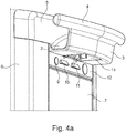
- FIG. 4a shows a detailed view of a multifunctional handle 1 according to the invention according to a further embodiment of the invention, which is mounted on a blood treatment machine or dialysis machine 6 and has an integrated media strip 12 with electrical or IT interfaces 9.
- the multifunctional handle also has openings 10. These openings 10 serve, for example, to reduce the attenuation of the signal of a loudspeaker mounted in the blood treatment machine, since the sound emitted by the loudspeaker from the blood treatment machine can escape through the openings 10 to the outside.
- the media strip 12 is arranged at the flank 7 of the blood treatment machine 6 protected by the multifunctional handle 1 from above from above, as viewed from the top of the blood treatment machine 6 behind / below the multifunctional handle 1.
- the line receiving portion 2 of the multifunctional handle 1 is formed in this embodiment as a section of a cylinder jacket surface which is convexly curved towards the top of the blood treatment machine 6.
- a cavity 13 is formed on the underside of the wire receiving portion 2 of the multifunctional handle 1.
- a fan fleece 11 via which the housing interior is connected to the atmosphere, is arranged.
- the lead receiving portion 2 of the multifunctional handle 1 limits the cavity 13 on three sides (top, left side, right side), the fan fleece 11 is shielded on the three sides against undesirable contact with the fingers, spray and other harmful influences. Due to the configuration of the multifunctional handle 1 or by the arrangement of the multifunctional handle 1 on the dialysis machine 6 access to the fan fleece 11 or any other arranged in the cavity 13 element is bent and thus very difficult. By this arrangement, the likelihood of unwanted touching the fan fleece 11 by operating personnel can be further reduced.
- the line receiving portion 2 of the multifunctional handle 1 is set in its dimensions and the arrangement of the electrical or and IT interfaces 9 on the integrated media strip 12 and the openings 10 is such that the resting on the line receiving portion 2 lines 8 due to the intrinsic Rigidity of the lines 8 sufficiently protrude from the multifunctional handle 1, that the interfaces 9 and also the openings 10 are not covered by the lines 8.
- FIG. 4b shows a frontal view of the multifunctional handle 1 from Fig. 4a , Accordingly, the fan fleece 11 is located above the media strip 12 and below the roof-shaped arched line receiving section 2.
Landscapes
- Health & Medical Sciences (AREA)
- Engineering & Computer Science (AREA)
- Heart & Thoracic Surgery (AREA)
- Urology & Nephrology (AREA)
- Anesthesiology (AREA)
- Animal Behavior & Ethology (AREA)
- Emergency Medicine (AREA)
- Veterinary Medicine (AREA)
- Public Health (AREA)
- Vascular Medicine (AREA)
- General Health & Medical Sciences (AREA)
- Biomedical Technology (AREA)
- Hematology (AREA)
- Life Sciences & Earth Sciences (AREA)
- Mechanical Engineering (AREA)
- Chemical & Material Sciences (AREA)
- Combustion & Propulsion (AREA)
- Transportation (AREA)
- Microelectronics & Electronic Packaging (AREA)
- External Artificial Organs (AREA)
Description
- Die vorliegende Erfindung betrifft einen multifunktionalen Griff einer mobilen Maschine zur extrakorporalen Blutbehandlung bzw. einer mobilen Blutbehandlungsmaschine zum händischen Bewegen der Blutbehandlungsmaschine sowie zum Aufwickeln von Leitungen und eine Blutbehandlungsmaschine mit einem solchen multifunktionalen Griff.
- Die moderne extrakorporale Blutbehandlung, beispielsweise die Dialyse, wird immer komplexer und flexibler. Besonders durch eine stetig zunehmende Anzahl technischer Neuerungen und zusätzlicher Behandlungsgeräte konnte der Standard klinischer Blutbehandlungen in den letzten Jahren kontinuierlich gehoben werden. Allerdings erhöht sich durch die zunehmende Anzahl neuer technischer Geräte auch der Druck, bestehenden Bauraum bei Blutbehandlungsmaschine besser zu nutzen, um mehr und mehr technische Funktionen in einer vorzugsweise mobilen Blutbehandlungsmaschine herkömmlicher Größe unterbringen zu können. Neben der Miniaturisierung von Bauteilen und anderen technischen Bestandteilen der Blutbehandlungsmaschine spielt hierbei vor Allem das Konzipieren multifunktionaler Bauteile eine Schlüsselrolle.
- Eine herkömmliche Blutbehandlungsmaschine ist beispielsweise aus der
WO 2004/028594A1 bekannt. Eine derartige mobile Blutbehandlungsmaschine weist an ihrer Außenseite mehrere separate Bauteile auf, um die Dialysemaschine händisch zu bewegen (zwei Griffe), um Fluidleitungen oder Kabel aufzuwickeln bzw. zu verstauen (eine Klemme) und, um die verschiedenen elektrischen bzw. IT-Schnittstellen der Dialysemaschine vor Spritzwasser zu schützen (ein erhöhter Rand an der tablettartig ausgebildeten Oberseite der Dialysemaschinen bzw. Abdeckungsklappen für die Schnittstellen). - Ein Wagen für ein Behandlungssystem ist beispielsweise aus der Druckschrift
EP 0240153 A1 bekannt. Dieser Wagen weist eine Griffstange auf, neben der mindestens ein Haken angeordnet ist. - Zudem offenbart die Druckschrift
US 2009/0012458A1 eine Dialysemaschine mit einem Griff in Form einer gebogenen Griffstange. - Bei der Blutbehandlungsmaschine gemäß der
US 2010/0089806 A1 ist die Griffstange als den Korpus der Blutbehandlungsmaschine kreisförmig umlaufender Handlauf ausgestaltet. Eine sehr ähnliche Ausgestaltung ist auch in der DruckschriftUS 2009/0084717A1 offenbart. - Weiterhin offenbart die Druckschrift
US 2011/0040242A1 einen Wagen für eine Dialysemaschine, bei welchem der Griff als Aussparung in der Tischplatte ausgestaltet ist. - Häufig weisen herkömmliche Blutbehandlungsmaschine insbesondere der mobilen Bauart noch zusätzlich Begrenzungselemente auf, die von dem Körper der Blutbehandlungsmaschine hervorragen und einer Beschädigung des Körpers bzw. des Gehäuses der Dialysemaschine aufgrund von Kollisionen mit z.B. Wänden während des Rangierens der Dialysemaschine vorbeugen sollen.
- Diese vielen separaten Bauteile beanspruchen bei der Konstruktion einer solchen Blutbehandlungsmaschine viel Bauraum, der daher nicht für unmittelbar dialyserelevante Bauteile verwendet werden kann. Aufgrund des beschränkten Bauraums können die verschiedenen Bauteile wie beispielsweise die Klemme zum Aufwickeln von Leitungen nur suboptimal positioniert werden, so dass oftmals auf die Klemme aufgewickelte Leitungen elektrische Schnittstellen und IT-Schnittstellen verdecken oder eine Bedienung der Dialysemaschine behindern.Zudem ist der Montageaufwand bei der Herstellung solcher Dialysemaschinen unnötig hoch, wodurch auch die Herstellungskosten derartiger Dialysemaschinen relativ hoch sind.
- Ausgehend von dem vorstehend beschriebenen Stand der Technik liegt der Erfindung die Aufgabe zugrunde, eine Blutbehandlungsmaschine, vorzugsweise Dialysemaschine der mobilen Bauart bereitzustellen, die sich durch eine effizientere Bauraumnutzung, geringere Herstellungskosten und geringeren Montageaufwand auszeichnet. Insbesondere die Aufgaben des Bewegens bzw. Rangierens der vorzugsweise mobilen Blutbehandlungsmaschine und der Aufbewahrung bzw. des Aufwickelns von mit der Blutbehandlungsmaschine verbundenen Leitungen bzw. Schläuchen, aber vorzugsweise auch die Aufgaben der Begrenzung der Blutbehandlungsmaschine bzw. des Schutzes der Blutbehandlungsmaschine bei möglichen Kollisionen und der Schutz verschiedener elektrischer Schnittstellen und IT-Schnittstellen der Blutbehandlungsmaschine vor Spritzwasser sollen durch einen einzigen multifunktionalen Griff erfüllt werden.
- Diese Aufgabe wird gelöst durch einen multifunktionalen Griff mit den Merkmalen gemäß dem Anspruch 1 und durch eine Blutbehandlungsmaschine, vorzugsweise Blutbehandlungsmaschine gemäß Anspruch 14 mit einem solchen multifunktionalen Griff. Vorteilhafte Weiterbildungen der Erfindung sind Gegenstand der Unteransprüche.
- Der Kerngedanke der vorliegenden Erfindung besteht demzufolge darin, mehrere Funktionen bzw. Aufgaben in einem einzigen multifunktionalen Bauteil insbesondere einem Multifunktionshandgriff zu vereinen. Der erfindungsgemäße Multifunktionshandgriff hat demzufolge wenigstens zwei (bauliche) Funktionsabschnitte, von denen der Eine für das Aufnehmen/Tragen von Leitungen/Schläuchen und der Andere für das ergonomische Ergreifen durch eine Bedienperson konstruktiv angepasst sind. Dabei sind die beiden Funktionsabschnitte erfindungsgemäß nicht adaptiv sondern integrativ miteinander verknüpft, derart, dass beide Funktionsabschnitte gleichzeitig auch zur Funktionserfüllung des jeweils anderen Funktionsabschnitts beitragen.
- In anderen Worten ausgedrückt hat ein Handgriff in der Regel einen mehr oder weniger ergonomisch geformten Greifabschnitt, der durch einen Abstandshalter von einer Gehäusewand oder dergleichen Bauteil beabstandet sein muss, um umfänglich stabil ergriffen werden zu können. Gemäß einem ersten Aspekt der Erfindung ist dieser Abstandshalter nunmehr zu einem Leitungs-/Schlauchträger (Aufnahme-/ Einhängabschnitt für Leitungen/Schläuche) geformt, wohingegen der Greifabschnitt gleichzeitig ein Rückhalte-/Sperrelement bildet, das ein Abgleiten/Abfallen der/des am Leitungs-/Schlauchträger aufgelagerten Leitung/Schlauchs über dessen freies Ende verhindert. Zusätzlich kann der Greifabschnitt so geformt/angeordnet sein, dass er entsprechend einer Stoßstange die Gehäusewand oder dergleichen Bauteil zumindest abschnittsweise umrahmt und somit einen Kollisionsschutz bildet.
- Gemäß dem Anspruch 1 wird folglich ein multifunktionaler Griff einer mobilen Blutbehandlungsmaschine, vorzugsweise (Hämo-) Dialysemaschine, zum händischen Bewegen der Blutbehandlungsmaschine sowie zum Aufwickeln oder Einhängen von Leitungen und/oder Schläuchen vorgeschlagen, der einen bügel- oder rinnenartigen Leitungsaufnahmeabschnitt und einen ergonomisch geformten Griffabschnitt hat, der an wenigstens einem Endbereich des bügel- oder rinnenartigen Leitungsaufnahmeabschnitts angeordnet oder ausgebildet ist. Dies bedeutet, dass der multifunktionale Griff (oder Multifunktionsgriff) neben der Bereitstellung einer ergonomisch geformten Greifgeometrie gleichzeitig eine für ein Aufhängen von biegeflexiblen Leitungen optimierte Halterung bildet, welche wiederum die Greifgeometrie von der Blutbehandlungsmaschine bzw. deren Gehäuse so beabstandet, dass sie von einer Bedienperson auch umgriffen werden kann. Durch diese integrative Gestaltung des Multifunktionsgriffs sind adaptive Einrichtungen wie zusätzliche Haken, die am Griff montiert werden oder zusätzliche, beispielsweise zapfenförmige Vorsprünge am Griff als Aufhängeinrichtungen überflüssig. Auch sind die entsprechende Formgebung des Leitungsaufnahmeabschnitts sowie die Positionierung des Griffabschnitts entscheidend dafür, dass bereits eingehängte Leitungen/Schläuche nicht unbeabsichtigt abgestreift werden können.
- Gemäß einer besonders bevorzugten Ausführungsform gemäß Anspruch 2 weist der Multifunktionshandgriff einen Abrutschverhinderungsabschnitt auf, der zwischen dem bügel-oder rinnenartigen Leitungsaufnahmeabschnitt und dem ergonomisch geformten Griffabschnitt angeordnet und hin zu der mobilen Blutbehandlungsmaschine derart gewölbt ist, dass ein Abrutschen von in dem bügel-oder rinnenartigen Leitungsaufnahmeabschnitt aufgenommenen Leitungen und / oder Schläuchen verhindert wird. Diese Ausgestaltung des Multifunktionshandgriffs ermöglicht ein besonders einfaches und sicheres Verwahren von Schläuchen auf dem Handgriff. Ein derartiger erfindungsgemäßer Multifunktionshandgriff kann daher nicht nur lediglich zweckfremd verwendet werden, sondern ist speziell für diese zweite Funktion ausgelegt, ohne dabei Funktionseinbußen bei der Erfüllung der Hauptfunktion zu erleiden.
- Eine bevorzugte Weiterbildung der Erfindung sieht vor, dass der Griffabschnitt handlauf- oder stangenartig ausgeformt ist und sich längs zu einer durch den Leitungsaufnahmeabschnitt definierten Leitungsaufnahmerichtung erstreckt. Dadurch kann der Griff beispielsweise auf Schulterbreite erstreckt werden, um so genügend manuelle Kraft auf die Blutbehandlungsmaschine zu deren Bewegung übertragen zu können.
- Vorzugsweise kann es vorgesehen sein, dass der Griffabschnitt an wenigstens einem quer zur Leitungsaufnahmerichtung sich befindlichen Ende (Stirnseite) des Leitungsaufnahmeabschnitts positioniert ist. In diesem Fall ist also der Griff vorzugsweise in zwei Griffteile zerlegt, die an den beiden in Leitungsaufnahmerichtung gesehenen Stirnseiten des Leitungsaufnahmeabschnitts angeordnet sind und diesen zwischen sich einschließen. Alternativ hierzu kann es aber auch vorgesehen sein, dass der Griffabschnitt an einem längs zur Leitungsaufnahmerichtung sich befindenden Ende des Leitungsaufnahmeabschnitts positioniert ist. Dieses Ende kann im Fall einer Bügelart quasi punktförmig und im Fall einer Rinnenart kantenförmig sein.
- Gemäß einem anderen, ggf. unabhängigen Aspekt der vorliegenden Erfindung kann es vorgesehen sein, dass der Leitungsaufnahmeabschnitt des multifunktionalen Griffs an seinem dem Griffabschnitt gegenüberliegenden Anschlussende fest mit der mobilen Blutbehandlungsmaschine (Hämodialysemaschine), vorzugsweise über ein Verbindungsstück oder Montageadapter, verbunden oder verbindbar ist. Dadurch wird eine eingehängte Leitung/Schlauch zwischen dem Griffabschnitt und der Blutbehandlungsmaschine aufgelagert und damit vor einem Abrutschen gesichert. Vorzugsweise dient dabei der Leitungsaufnahmeabschnitt des multifunktionalen Griffs als Abstandshalter des Griffabschnitts zur Blutbehandlungsmaschine.
- Des Weiteren kann es vorgesehen sein, dass der vorzugsweise handlauf- oder stangenartige Griffabschnitt an mindestens einem und vorzugsweise beiden seiner Längsenden in Leitungsaufnahmerichtung gesehen über den Leitungsaufnahmeabschnitt vorragt. Somit übernimmt der Griffabschnitt nicht nur die Funktion, manuelle Kraft einer Bedienperson auf die Maschine zu übertragen sondern auch die Maschine/das Maschinengehäuse vor Aufprallschäden zu schützen.
- Vorteilhaft kann es sein, wenn der Leitungsaufnahmeabschnitt in Leitungsaufnahmerichtung gesehen schalenförmig gewölbt ausgebildet ist, um auf diese Weise ein Abknicken der eingehängten Leitungen und/oder Schläuche zu vermeiden. Vorzugsweise ist der Leitungsaufnahmeabschnitt als flächiges, vorzugsweise plattenartiges Bauteil ausgebildet. Er bietet somit eine glatte Auflagefläche, wodurch Beschädigungen an den Leitungen/Schläuchen verhinderbar sind.
- Zur einfachen und kostengünstigen Herstellung kann der multifunktionale Griff vorzugsweise mit einem Verbindungsstück oder Montageadapter stoffeinstückig aus Metall oder Kunststoff gefertigt sein.
- Schließlich betrifft ein anderer Aspekt der vorliegenden Erfindung die Bereitstellung einer Blutbehandlungsmaschine vorzugsweise mit einem Maschinengehäuse an der/dem ein multifunktionaler Griff gemäß der Erfindung montiert ist.
- Aus der vorstehenden Beschreibung der Erfindung ist ersichtlich, dass der multifunktionale Griff infolge seiner Bügel- oder Rinnenbauart den Schlauchaufnahmeabschnitt bzw. Auflageabschnitt, um welchen Leitungen zur Verwahrung gewickelt werden können, und vorzugsweise einen mit dem Auflageabschnitt verbundenen Abrutschverhinderungsbereich ausbildet, der von dem Auflageabschnitt an dessen freien Endbereich in einem Winkel vorragt und somit ein Abrutschen von auf dem Auflageabschnitt verwahrten Leitungen über dessen freien Endbereich verhindert. Die Besonderheit des multifunktionalen Griffs gemäß der Erfindung liegt darin, dass der Abrutschverhinderungsabschnitt durch eine zumindest partiell ergonomische Ausgestaltung für das Ergreifen durch eine Hand ausgelegt ist, wodurch die Funktionen "leichtes/ergonomisches Ergreifen" und "Verhindern des Abrutschens aufgewickelter Leitungen" in einem baulichen Abschnitt des multifunktionalen Griffs vereint werden. Zusätzlich kann beispielsweise der Auflageabschnitt des multifunktionalen Griffs als von dem Körper/Bauteil bzw. dem Gehäuse der Blutbehandlungsmaschine (Hämodialysemaschine) vorragender, vorzugsweise flächiger Abschnitt ausgebildet sein, der zudem nach Art eines hervorstehenden (Wölb-) Daches an dem Gehäuse der Maschine angeordnete elektrische Anschlüsse und/oder IT-Schnittstellen von Spitzwasser abschirmt. Somit lassen sich auch die Funktionen " Verwahrung von Leitungen" und "Schutz vor Spritzwasser" in einem baulichen Abschnitt des multifunktionalen Griffs vereinen.
- Der Ausgestaltung des multifunktionalen Griffs gemäß Anspruch 1 liegt somit das Konstruktionskonzept zugrunde, jeden baulichen Abschnitt des Griffs möglichst so zu konzipieren, dass dieser eine bauliche Abschnitt für die Erfüllung möglichst vieler verschiedener Funktionen angepasst ist und somit die Funktionalität des gesamten Multifunktionsgriffs auf einen möglichst weiten Aufgabenbereich ausgedehnt werden kann.
- Durch den multifunktionalen Griff gemäß der vorliegenden Erfindung lassen sich der Montageaufwand und die Herstellungskosten einer vorzugsweise mobilen Blutbehandlungsmaschinen wie einer Hämodialysemaschine reduzieren, da anstatt mehrerer separater Bauteile zur Erfüllung der Aufgaben "Rangieren", "Aufbewahren", "Begrenzen" und "Schutz empfindlicher Schnittstellen gegen Spritzwasser" nur ein einziges Bauteil, nämlich der multifunktionale Griff gemäß der Erfindung, montiert werden muss. Durch die effizientere Bauraumnutzung erhöht sich auch die Flexibilität bei der technischen Ausgestaltung der Blutbehandlungsmaschine (Hämodialysemaschine). So muss beispielsweise die tablettartig ausgestaltete Oberseite der Maschine keinen hohen Rand mehr aufweisen, der ein Greifen von auf der Oberseite abgestellten Gegenständen behindern kann, da die Abschirmung von empfindlichen elektrischen und IT- Schnittstellen der Maschine bereits durch den multifunktionalen Griff erfolgt.
- Abschließend sei darauf hingewiesen, dass der Schlauchaufnahmeabschnitt/Auflageabschnitt nicht notwendiger Weise als Fläche (Platte) ausgebildet sein muss, sondern auch aus mindestens einer Stange bestehen kann, von der ein Abrutschverhinderungsabschnitt in Form einer zweiten Stange in einem definierten Winkel aufragt und dadurch die Bügelart definiert. Zum verbesserten Greifen kann der Abrutschverhinderungsabschnitt beispielsweise an dem dem Auflageabschnitt abgewandten (freien) Ende der Stange eine Griffkugel oder eine Griffstange bzw. einen Handlauf aufweisen. Weiterhin alternativ können der Auflageabschnitt und der Abrutschverhinderungsabschnitt des multifunktionalen Griffs in einer einzigen gebogenen Stange oder Platte (Hakenform) baulich integriert sein. In diesem Falle bestimmt die Biegung der Stange den Winkel zwischen dem Auflageabschnitt und dem Abrutschverhinderungsabschnitt des multifunktionalen Griffs.
- In einer vorteilhaften Ausführungsform ist der Winkel zwischen dem Auflageabschnitt und dem Abrutschverhinderungsabschnitt im Wesentlichen rechtwinklig. Hierdurch wird ein im Wesentlichen L-förmiger Griff (im Querschnitt) gebildet.
- Vorteilhafterweise ragt bei dieser Anordnung der Auflageabschnitt des multifunktionalen Griffs rechtwinklig von dem Körper bzw. dem Gehäuse der Blutbehandlungsmaschine vor und der Abrutschverhinderungsabschnitt ragt im Wesentlichen rechtwinklig von dem Auslageabschnitt hin zu der Oberseite der Blutbehandlungsmaschine vor, sodass zwischen dem Abrutschverhinderungsabschnitt und der Oberfläche des Körpers bzw. Gehäuses der Blutbehandlungsmaschine quasi eine Mulde/Rinne gebildet wird. Wird der ergonomisch ausgeformte Abrutschverhinderungsabschnitt zum Rangieren der mobilen Blutbehandlungsmaschine ergriffen, so befindet sich die Mulde/Rinne von der den multifunktionalen Griff ergreifenden Bedienperson aus gesehen hinter dem Abrutschverhinderungsabschnitt. Da die Mulde/Rinne der Aufnahme von Leitungen dient, ist diese Anordnung besonders vorteilhaft, da in der Mulde/Rinne liegende, um den Auflageabschnitt des multifunktionalen Griffs aufgewickelte Leitungen bei dieser Anordnung ein Ergreifen des Abrutschverhinderungsabschnitts des multifunktionalen Griffs nicht behindern.
- Alternativ kann der Abrutschverhinderungsabschnitt des multifunktionalen Griffs an seiner dem Auflageabschnitt abgewandten Seite fest mit der Oberfläche des Körpers bzw. des Gehäuses der Blutbehandlungsmaschine, vorzugsweise über ein Verbindungsstück, verbunden sein. Bei einer derartigen Rücken- an- Rücken- Verbindung zwischen dem multifunktionalen Griff und dem Körper der Blutbehandlungsmaschine bildet der Auflageabschnitt des multifunktionalen Griffs eine Auflagefläche für aufgewickelte Kabel, die von einer den multifunktionalen Griff ergreifenden Bedienperson aus gesehen, vor dem Abrutschverhinderungsabschnitt liegt. Um ein Abrutschen von auf der Auflagefläche liegenden, um den Auflageabschnitt des multifunktionalen Griffs aufgewickelten Leitungen zu verhindern, kann in dieser Ausführungsform das dem Abrutschverhinderungsabschnitt abgewandte Ende des Auflageabschnitts nach oben, d.h. in Richtung hin zu der Oberseite der Blutbehandlungsmaschine gebogen sein und somit als zweiter, zusätzlicher Abrutschverhinderungsabschnitt dienen. In diesem Fall würde der Griff im Querschnitt quasi eine U-Form annähern.
- Ein Vorteil der geschilderten Anordnungen des multifunktionalen Griffs an dem Körper einer Blutbehandlungsmaschine besteht darin, dass der Auflageabschnitt von dem Körper bzw. dem Gehäuse der Blutbehandlungsmaschine im Wesentlichen rechtwinklig vorsteht. Werden empfindliche elektrische Schnittstellen oder IT-Schnittstellen am Körper der Blutbehandlungsmaschine von der Oberseite der Blutbehandlungsmaschine betrachtet unter dem Auflageabschnitt des multifunktionalen Griffs angeordnet, so schirmt der vorstehende Auflageabschnitt die elektrischen bzw. IT-Schnittstellen nach Art eines hervorstehenden Daches vor von oben herabfallendem Spritzwasser ab. Die Notwendigkeit separater Abdeckungen für diese Schnittstellen entfällt daher durch die Ausgestaltung des multifunktionalen Griffs.
- Da der multifunktionale Griff zudem als Begrenzungselement dient, d. h. ähnlich zu einer Stoßstange die Blutbehandlungsmaschine bei Kollisionen schützt, entfällt zudem die Notwendigkeit eines separaten Begrenzungselements.
- Weiterhin wird gemäß einer vorteilhaften Abwandlung des multifunktionalen Griffs das Rangieren der mobilen Blutbehandlungsmaschine dadurch erleichtert, dass die Griffstange an mindestens einem ihrer Enden über den Auflageabschnitt in Auflagerichtung gesehen vorragt. Besonders vorteilhaft ist es, wenn die Griffstange bzw. der Handlauf an ihren bzw. seinen beiden Enden um eine gleiche Länge über den Auflageabschnitt vorragt, da diese Anordnung sowohl ein Rangieren der mobilen Blutbehandlungsmaschine nach links als auch nach rechts erleichtert.
- Gemäß einer weiteren vorteilhaften Ausgestaltung ist mindestens einer von dem Auflageabschnitt und dem Abrutschverhinderungsabschnitt des multifunktionalen Griffs gekrümmt ausgebildet. Beispielsweise ist der Auflageabschnitt, der die Mulde/Rinne bzw. Auflagefläche zur Aufnahme von Leitungen bildet, als Mantelfläche eines Halbzylinders ausgebildet. Eine derartige Ausgestaltung verhindert eine Herabrutschen bzw. Herausfallen der Leitungen von der Auflagefläche bzw. der Mulde/Rinne. Der von dem Auflageabschnitt aufragende Abrutschverhinderungsabschnitt kann derart gewölbt sein, dass er eine beispielsweise konvexe Wölbung der Oberfläche des Körpers der Blutbehandlungsmaschine nachbildet. Zusätzlich oder alternativ kann auch der Abrutschverhinderungsabschnitt als eine Mantelfläche eines Halbzylinders ausgebildet sein, der hin zu der Oberfläche des Körpers bzw. des Gehäuses der Blutbehandlungsmaschine konvex gewölbt ist. Bei einer derartigen Ausgestaltung werden zwischen dem Abrutschverhinderungsabschnitt und der Oberfläche des Körpers der Blutbehandlungsmaschine aufbewahrte Leitungen durch die Wölbung des Abrutschverhinderungsabschnitt eingeklemmt, wodurch ein Herausfallen der Leitungen aus der Lagerposition verhindert wird.
- Zudem bietet die Reduktion der Anzahl der an der Blutbehandlungsmaschine befindlichen Kleinteile auch hygienische Vorteile: Durch den multifunktionalen Griff entstehen große, ebene, abgerundete und spaltfreie Flächen, die einfach zu reinigen sind. Dies ist insbesondere im hektischen klinischen Alltag essentiell, da Oberflächen häufig gereinigt werden müssen, hierfür aber oftmals nicht viel Zeit zur Verfügung steht.
- Zur weiteren Verbesserung der Effizienz der Bauraumnutzung der Blutbehandlungsmaschine kann der multifunktionale Griff auch als Plattform zur Integration von weiteren für die Dialyse notwendigen Bauteilen und Schnittstellen genutzt werden. So können beispielsweise Belüftungsvorrichtungen oder IT-Schnittstellen bzw. Anschlüsse in dem multifunktionalen Griff integriert werden. Beispielsweise kann der multifunktionale Griff entlang seiner Länge (In Aufnahmerichtung gesehen) Schienen aufweisen, die der Führung eines Lüftervlieses dienen. So erhöhen sich die Möglichkeiten, die Belüftungsvorrichtung möglichst vorteilhaft anzuordnen und den zur Verfügung stehenden Bauraum optimal zu nutzen. Auch verschiedene Anschlüsse, beispielsweise zum Anschließen verschiedener Kabel, können vorzugsweise an den seitlichen Enden oder der Unterseite des multifunktionalen Griffs angeordnet sein.
- Zudem kann der multifunktionale Griff auch eine integrierte Medienleiste, welche vorzugsweise unter dem Leitungsaufnahmeabschnitt an dem Körper der Blutbehandlungsmaschine angeordnet ist, aufweisen. Durch diese Anordnung schirmt der Leitungsaufnahmeabschnitt des multifunktionalen Griffs die verschiedenen Anschlüsse und Schnittstellen von von oben herabfallendem Spritzwasser ab. Vorteilhafterweise ist der multifunktionale Griff hierbei so ausgebildet, dass die verschiedenen Anschlüsse auch dann zugänglich sind, wenn Leitungen auf dem Leitungsaufnahmeabschnitt aufgewickelt sind.
- Gemäß einer vorteilhaften Ausgestaltung ist der Leitungsaufnahmeabschnitt derart ausgebildet, dass er an seiner Unterseite einen Hohlraum bildet. Beispielsweise ist der Leitungsaufnahmeabschnitt gekrümmt bzw. als konvex nach oben gewölbter Ausschnitt einer Zylindermantelfläche ausgebildet. Durch diese geometrische Ausgestaltung des Leitungsaufnahmeabschnitts wird ein von drei Seiten durch den multifunktionalen Griff begrenzter Hohlraum in dem multifunktionalen Griff an der Unterseite des multifunktionalen Griffs geschaffen. In diesem Hohlraum kann beispielsweise ein funktionelles Bauteil wie ein Lüftervlies angeordnet sein. Dies hat den Vorteil, dass der multifunktionale Griff das Lüftervlies von drei Seiten gegen ungewollte Berührungen mit den Fingern oder sonstige schädigende Einflüsse abschirmt. Zudem ist der Zugang zu dem Lüftervlies sehr verwinkelt, wodurch die Wahrscheinlichkeit beispielsweise einer ungewollten Berührung des Lüftervlieses weiter reduziert wird.
- Die Erfindung wird nachstehend anhand bevorzugter Ausführungsbeispiele unter Bezugnahme auf die begleitenden Figuren näher erläutert.
-
-
Fig. 1a bis 1f unterschiedliche Konstruktionsbeispiele eines erfindungsgemäßen multifunktionalen Griffs, jeweils mit einem bügel- oder rinnenartigen Leitungsaufnahmeabschnitt (nachfolgend in Auflagebereich/-abschnitt und Abrutschverhinderungsbereich/-abschnitt untergliedert) und einen ergonomisch geformten Griffabschnitt, -
Fig. 2 eine Blutbehandlungsmaschine (nachfolgend grundsätzlich als Dialysemaschine bezeichnet), an der der erfindungsgemäße multifunktionale Griff über ein Verbindungs- oder Adapterstück montiert ist, und -
Fig. 3 die Dialysemaschine gemäß derFig. 2 mit dem erfindungsgemäßen multifunktionalen Griff, auf welchem Leitungen oder Schläuche aufgewickelt sind. -
Fign.4a undb jeweils eine Detailansicht aus einem unterschiedlichen Blickwinkel eines erfindungsgemäßen multifunktionalen Griffs gemäß einer weiteren Ausführungsform der Erfindung, welcher an einer Dialysemaschine montiert ist und eine integrierte Medienleiste mit elektrischen und IT-Schnittstellen, sowie einen Hohlraum zur Abschirmung eines Lüftervlieses aufweist. -
Fig. 1a zeigt die ersten Ausführungsform eines multifunktionalen Griffs 1 für eine Blutbehandlungs- bzw. Dialysemaschine zum händischen Bewegen der Dialysemaschine sowie zum Aufwickeln von Leitungen und/oder Schläuchen, mit einem flächigen, bzw. plattenförmigen Auflagebereich/-abschnitt 2 und einem flächigen bzw. plattenförmigen Abrutschverhinderungsbereich/-abschnitt 3, der an einem ersten kantenartigen Ende 2a des Auflageabschnitts 2 in einem Winkel von dem Auflageabschnitt 2 absteht. Die Abschnitte 2 und 3 bilden zusammen eine im Querschnitt V- oder L-förmige Rinne, welche im Zusammenwirken einen Leitungsaufnahmeabschnitt des Multifunktionshandgriffs definieren. - In dieser Ausführungsform ist der multifunktionale Griff 1 einstückig gefertigt und der Winkel zwischen dem Auflageabschnitt 2 und dem Abrutschverhinderungsabschnitt 3 ist im Wesentlichen rechtwinklig, kann aber auch ein spitzer oder stumpfer Winkel sein. Durch die im Wesentlichen rechtwinklige Anordnung entsteht der im Wesentlichen L-förmige Griff 1, bei dem die Fläche des Auflageabschnitts 2 die alleinige Auflage für Leitungen bildet, die um den Griff 1 aufgewickelt verwahrt werden können, wohingegen der Abrutschverhinderungsabschnitt 3 alleinig ein unbeabsichtigtes Abgleiten der bereits aufgewickelten Leitungen/Schläuche über die freie Kante des Auflageabschnitts 2 verhindern soll.
- An seinem dem Auflageabschnitt 2 abgewandten, freien (kantenförmigen) Ende 3b weist der Abrutschverhinderungsabschnitt 3 zum verbesserten Greifen des Griffs 1 und zum vereinfachten Rangieren der mobilen Dialysemaschine, an der der multifunktionale Griff 1 fixiert ist, eine Griffstange bzw. einen Handlauf 4 auf, die bzw. der entlang der Kante des dem Auflageabschnitt 2 abgewandten Endes 3b des Abrutschverhinderungsabschnitts 3 verläuft. Die Griffstange 4 ragt hierbei an ihren beiden Enden um eine gleiche Länge über den Abrutschverhinderungsabschnitt 3 vor. Dies ermöglicht ein einfaches Rangieren der mobilen Dialysemaschine nach rechts und links und schützt zudem das Gehäuse der Dialysemaschine bei Kollisionen.
- Die Oberfläche des gesamten multifunktionalen Griffs 1 besteht aus großen, spaltfreien und hinterschneidungsfreien Flächen mit abgerundeten Ecken. Dies vereinfacht die Reinigung des Griffs 1. Außerdem beugt es Beschädigungen der aufgewickelten Leitungen/Schläuchen etwa durch Knicken oder Eindrücken vor.
- Der multifunktionale Griff 1 kann an dem zweiten (dem Abrutschverhinderungsabschnitt 3 abgewandten) Ende 2b des Auflageabschnitts 2 mit der Dialysemaschine, vorzugsweise über ein Verbindungs-/Adapterstück, verbunden werden. Bei dieser Anordnung liegt die durch den Auflageabschnitt 2 gebildete Auflagefläche für Leitungen zwischen der Oberfläche der Dialysemaschine und dem Abrutschverhinderungsabschnitt 3 mit dem daran angeordneten Handlauf/Griffstange 4. Da ein Benutzer den multifunktionalen Griff 1 an der Griffstange 4 greift, befindet sich die Auflagefläche daher, von dem Ergreifenden betrachtet, hinter der Griffstange 4 und etwaige auf der Auflagefläche befindliche Leitungen behindern somit ein Ergreifen des multifunktionalen Griffs 1 an der Griffstange 4 nicht.
- Alternativ kann der multifunktionale Griff 1 auch an der durch den Abrutschverhinderungsabschnitt 3 gebildeten Fläche nach Art einer Rücken-an-Rücken-Verbindung mit der Dialysemaschine verbunden werden. Die durch den Auflageabschnitt 2 gebildete Auflagefläche befindet sich in dieser Anordnung, von dem Ergreifenden betrachtet, vor der Griffstange 4. Eine derartige Anordnung kann unter Umständen das Aufwickeln von Leitungen um den multifunktionalen Griff 1 erleichtern, da die Leitungen nicht um die Griffstange herumgeführt werden müssen. Jedoch wäre es in diesem Fall empfehlenswert, anstelle der vorstehend beschriebenen L-Form eine V- oder U-Form für den Leitungsaufnahmebereich zu wählen, um auch in diesem Fall ein unbeabsichtigtes Abrutschen der aufgewickelten Leitungen zu vermeiden.
- Der Abrutschverhinderungsabschnitt 3 kann gemäß der
Fig. 1 a gerade oder gewölbt ausgebildet sein, so dass der Abrutschverhinderungsabschnitt 3 die Wölbung einer Oberfläche der Dialysemaschine, an der der multifunktionale Griff 1 montiert ist, nachbildet. -
Fig. 1b zeigt einen erfindungsgemäßen multifunktionalen Griff 1, bei dem der Auflageabschnitt 2 per se (tonnenförmig) gerundet ausgebildet ist, so dass eine Aufnahmemulde/-rinne zur verbesserten Aufnahme von Leitungen gebildet wird. Dieselben Bezugszeichen, die auch in den übrigen Figuren verwendet werden, beziehen sich auf dieselben oder sehr ähnliche Bauteile. - Die gerundete Ausbildung des Auflageabschnitts 2 ermöglicht es, den multifunktionalen Griff 1 kompakter auszubilden, so dass der multifunktionale Griff 1 um eine geringere Distanz von der Dialysemaschine vorsteht, als ein vergleichbarer multifunktionaler Griff 1, bei dem der Auflageabschnitt 2 plan ausgebildet ist, wie in der
Fig. 1a gezeigt wird. Zusätzlich kann der Abrutschverhinderungsabschnitt 3 gewölbt ausgebildet sein, so dass der Abrutschverhinderungsabschnitt 3 die Wölbung einer Oberfläche der Dialysemaschine, an der der multifunktionale Griff 1 montiert ist, nachbildet. -
Fig. 1c zeigt eine weitere Ausgestaltung eines erfindungsgemäßen multifunktionalen Griffs 1, bei dem die Fläche des Abrutschverhinderungsabschnitts 3 hin zu der Fläche des Auflageabschnitts 2 (tonnenförmig) gerundet ist. Bei der in dieser Figur dargestellten Ausgestaltung ist die Fläche des Auflageabschnitts 2 ebenfalls wie in derFig. 1b gerundet ausgebildet, so dass eine vertiefte Aufnahmemulde/-rinne entsteht. Alternativ kann die Fläche des Auflageabschnitts 2 aber auch plan sein (nicht weiter gezeigt). Durch die gerundete Ausgestaltung des Abrutschverhinderungsabschnitts 3 gemäß derFig. 1c kann vor allem bei einer Anordnung des multifunktionalen Griffs 1, bei der der multifunktionale Griff 1 an dem zweiten, dem Abrutschverhinderungsabschnitt 3 abgewandten (kantenförmigen) Ende 2b des Auflageabschnitts 2 mit der Dialysemaschine verbunden ist, ein unerwünschtes Herabfallen von in der Auflagemulde befindlichen Leitungen verhindert werden, da die Leitungen zwischen der Wölbung des Abrutschverhinderungsabschnitts 3 und der Oberfläche der Dialysemaschine quasi eingeklemmt sind. - In der
Fig. 1e ist eine alternative Ausführungsform zum Ausführungsbeispiel gemäß derFig. 1a gezeigt. In diesem Fall ist die Griffstange 4 nicht unmittelbar am freien (kantenförmigen) Ende 3b des Leitungsaufnahmeabschnitts/-bereichs sondern in dessen Mittenabschnitt platziert. Die Griffstange 4 ist in zwei Teile gegliedert, die jeweils an einer in Auflage-/Aufwickelrichtung gesehenen Stirnkante des Leitungsaufnahmeabschnitts/-bereichs fixiert sind und so den Leitungsaufnahmeabschnitt/- bereich zwischen sich aufnehmen. Diese Variante hat den Vorteil, dass beispielsweise zwei unterschiedliche Leitungen/Schläuche eingehängt werden können, welche von der zweigeteilten Griffstange 4 voneinander separiert werden können. - An dieser Stelle sei darauf hingewiesen, dass der Leitungsaufnahmeabschnitt/- bereich nicht notwendiger Weise plattenförmig sondern auch stangenförmig sein kann, wie dies in den
Fig. 1d und 1f gezeigt ist. In diesem Fall sind der Auflageabschnitt 2 und/oder der Abrutschverhinderungsabschnitt 3 aus zumindest einer Stange gebildet. In diesem Fall kann der Griff eine Griffstange 4 haben, wie diese in derFig. 1f dargestellt ist oder es können ein oder zwei Griffkugeln/Knöpfe an den freien Stangenenden angeordnet sein, welche gleichzeitig auch den Abrutschverhinderungsabschnitt 3 definieren können. Diese Variante ist in derFig. 1 d gezeigt. -
Fig. 2 zeigt eine Blutbehandlungsmaschine/ (Hämo-) Dialysemaschine 6, an der ein multifunktionaler Griff 1 gemäß der vorliegenden Erfindung über ein Verbindungsstück 5 fixiert ist. Hierbei ist der multifunktionale Griff 1 mit dem zweiten, dem Abrutschverhinderungsabschnitt 3 abgewandten (kantenförmigen) Ende 2b des Auflageabschnitts 2 mit dem Verbindungsstück 5 verbunden, welches fest an der Dialysemaschine 6 angebracht ist/wird. Bei dieser Anordnung befindet sich die durch den Auflageabschnitt 2 gebildete Auflagefläche bzw. -rinne für Leitungen zwischen der Griffstange 4 bzw. dem Abrutschverhinderungsabschnitt 3 und der Oberfläche der Dialysemaschine 6. Der Griff entspricht somit dem bereits vorstehend beschriebenen Griff gemäß derFig. 1 a. - In dieser Darstellung ist klar zu erkennen, wie der von der Oberfläche der Dialysemaschine 6 vorragende Auflageabschnitt 2 des multifunktionalen Griffs 1 die Flanke/Seitenwand 7 der Dialysemaschine 6 nach Art eines vorstehenden Daches vor von oben herabfallendem Spritzwasser schützt. Werden elektrische bzw. IT-Schnittstellen an der durch den hervorstehenden multifunktionalen Griff 1 derart geschützten Flanke 7 der Dialysemaschine 6 angeordnet, so entfällt das Erfordernis für separate Abdeckungen zum Schutz dieser Schnittstellen vor Spritzwasser.
- In dieser Ausgestaltung ist die Baugruppe aus multifunktionalem Griff 1 und Verbindungsstück 5 stoffeinstückig gefertigt. Es kann aber auch sein, den Multifunktionsgriff 1 als Universalgriff zu konzipieren der dann mit unterschiedlichen Verbindungs-/Adapterstücken 5 kombinierbar ist, welche für unterschiedliche Blutbehandlungsmaschinen angepasst sind.
-
Fig. 3 zeigt eine Detailansicht eines multifunktionalen Griffs 1, der an einer Dialysemaschine 6 montiert ist. In dieser Darstellung sind von der Baugruppe aus multifunktionalem Griff 1 und Verbindungsstück 5 der Abrutschverhinderungsabschnitt 3 und die Griffstange 4 des multifunktionalen Griffs 1, sowie das Verbindungsstück 5 zu sehen. Der Auflageabschnitt 2 des multifunktionalen Griffs 1 liegt unter den auf den multifunktionalen Griff 1 aufgewickelten Leitungen 8 und ist daher in dieser Darstellung nicht sichtbar. Ein Benutzer ergreift die Griffstange 4 an ihrem rechten, über den Abrutschverhinderungsabschnitt 3 des multifunktionalen Griffs 1 hervorragenden Ende. Die Leitungen 8 liegen bei Betrachtung von dem den multifunktionalen Griff 1 Ergreifenden aus betrachtet, hinter der Griffstange 4 und behindern daher ein Ergreifen der Griffstange 4 nicht. - Der Abrutschverhinderungsabschnitt 3, sowie die Griffstange 4 sind gewölbt ausgebildet, so dass sie die Wölbung der Oberfläche der Dialysemaschine 6 bzw. des Verbindungsstücks 5 nachbilden. Der multifunktionale Griff 1 dient hierbei auch als Begrenzungselement für die Dialysemaschine 6, da er nach Art einer Stoßstange das Gehäuse der Dialysemaschine 6 bei einer Kollision mit Wänden oder ähnlichem schützt.
-
Fig.4a zeigt eine Detailansicht eines erfindungsgemäßen multifunktionalen Griffs 1 gemäß einer weiteren Ausführungsform der Erfindung, welcher an einer Blutbehandlungsmaschine bzw. Dialysemaschine 6 montiert ist und eine integrierte Medienleiste 12 mit elektrischen bzw. IT-Schnittstellen 9 aufweist. Zusätzlich weist der multifunktionale Griff auch Öffnungen 10 auf. Diese Öffnungen 10 dienen beispielsweise dazu, die Dämpfung des Signals eines in der Blutbehandlungsmaschine montierten Lautsprechers zu reduzieren, da durch die Öffnungen 10 der von dem Lautsprecher ausgesandte Schall aus der Blutbehandlungsmaschine nach außen dringen kann. - Die Medienleiste 12 ist an der durch den multifunktionalen Griff 1 vor von oben kommendem Spritzwasser geschützten Flanke 7 der Blutbehandlungsmaschine 6 bei Betrachtung von der Oberseite der Blutbehandlungsmaschine 6 her hinter /unter dem multifunktionalen Griff 1 angeordnet. Der Leitungsaufnahmeabschnitt 2 des multifunktionalen Griffs 1 ist in dieser Ausgestaltung als ein Ausschnitt einer Zylindermantelfläche ausgebildet, der hin zu der Oberseite der Blutbehandlungsmaschine 6 konvex gewölbt ist. Durch diese geometrische Ausgestaltung des Leitungsaufnahmeabschnitts 2 des multifunktionalen Griffs 1 wird ein Hohlraum 13 an der Unterseite des Leitungsaufnahmeabschnitts 2 des multifunktionalen Griffs 1 gebildet. In diesem Hohlraum 13 ist ein Lüftervlies 11, über welches das Gehäuseinnere mit der Atmosphäre verbunden ist, angeordnet. Da der Leitungsaufnahmeabschnitt 2 des multifunktionalen Griffs 1 den Hohlraum 13 an drei Seiten (Oberseite, linke Seite, rechte Seite) begrenzt, ist das Lüftervlies 11 an den drei Seiten vor unerwünschten Berührungen mit den Fingern, Spritzwasser und sonstigen schädigenden Einflüssen abgeschirmt. Durch die Ausgestaltung des multifunktionalen Griffs 1 bzw. durch die Anordnung des multifunktionalen Griffs 1 an der Dialysemaschine 6 ist der Zugang zu dem Lüftervlies 11 oder jedem anderen beliebigen in dem Hohlraum 13 angeordneten Element verwinkelt und somit sehr erschwert. Durch diese Anordnung läßt sich die Wahrscheinlichkeit unerwünschter Berührungen des Lüftervlieses 11 durch Bedienpersonal weiter reduzieren.
- Der Zugang zu den an der integrierten Medienleiste 12 angeordneten elektrischen bzw. IT-Schnittstellen 9 ist auch dann gewährleistet, wenn Leitungen auf dem Leitungsaufnahmeabschnitt 2 des multifunktionalen Griffs 1 aufgewickelt sind. Hierfür ist der Leitungsaufnahmeabschnitt 2 des multifunktionalen Griffs 1 so in seinen Abmessungen eingestellt und die Anordnung der elektrischen bzw. und IT-Schnittstellen 9 an der integrierten Medienleiste 12 und der Öffnungen 10 ist derart, dass die auf dem Leitungsaufnahmeabschnitt 2 aufliegenden Leitungen 8 aufgrund der intrinsischen Steifigkeit der Leitungen 8 genügend von dem multifunktionalen Griff 1 abstehen, dass die Schnittstellen 9 und auch die Öffnungen 10 nicht von den Leitungen 8 verdeckt werden.
-
Fig.4b zeigt eine Frontalansicht des multifunktionalen Griffs 1 ausFig. 4a . Demnach befindet sich das Lüftervlies 11 oberhalb der Medienleiste 12 und unterhalb des dachförmig gewölbten Leitungsaufnahmeabschnitts 2.
Claims (16)
- Multifunktionaler Griff (1) einer mobilen Blutbehandlungsmaschine (6) zum händischen Bewegen der Blutbehandlungsmaschine (6) sowie zum Aufwickeln oder Einhängen von Leitungen und/oder Schläuchen (8), umfassend einen bügel- oder rinnenartigen Leitungsaufnahmeabschnitt (2) und einen ergonomisch geformten Griffabschnitt, der an wenigstens einem Endbereich des bügel- oder rinnenartigen Leitungsaufnahmeabschnitts angeordnet oder ausgebildet ist, und gekennzeichnet dadurch, dass der Leitungsaufnahmeabschnitt (2) einen Hohlraum (13) zur besonders abgeschirmten Unterbringung eines funktionellen Bauteils ausbildet.
- Multifunktionaler Griff (1) einer mobilen Blutbehandlungsmaschine (6) gemäß Anspruch 1, mit einem Abrutschverhinderungsabschnitt (3), der zwischen dem bügel-oder rinnenartigen Leitungsaufnahmeabschnitt (2) und dem ergonomisch geformten Griffabschnitt (4) angeordnet und hin zu der mobilen Blutbehandlungsmaschine (6) derart gewölbt ist, dass ein Abrutschen von in dem bügel- oder rinnenartigen Leitungsaufnahmeabschnitt (2) aufgenommenen Leitungen und / oder Schläuchen (8) verhindert wird.
- Multifunktionaler Griff (1) nach Anspruch 1 oder 2, dadurch gekennzeichnet, dass der Griffabschnitt handlauf- oder stangenartig ausgeformt ist und sich längs zu einer durch den Leitungsaufnahmeabschnitt definierten Leitungsaufnahmerichtung erstreckt.
- Multifunktionaler Griff (1) nach Anspruch 3, dadurch gekennzeichnet, dass der Griffabschnitt an einem quer zur Leitungsaufnahmerichtung sich befindenden Ende des Leitungsaufnahmeabschnitts positioniert ist.
- Multifunktionaler Griff (1) nach Anspruch 3, dadurch gekennzeichnet, dass der Griffabschnitt an einem längs zur Leitungsaufnahmerichtung sich befindenden Ende des Leitungsaufnahmeabschnitts positioniert ist.
- Multifunktionaler Griff (1) nach einem der vorhergehenden Ansprüche, dadurch gekennzeichnet, dass der Leitungsaufnahmeabschnitt (2) des multifunktionalen Griffs (1) an einem dem Griffabschnitt gegenüberliegenden Anschlussende fest mit der mobilen Blutbehandlungsmaschine (6), vorzugsweise über ein Verbindungsstück oder Montageadapter (5), verbunden oder verbindbar ist.
- Multifunktionaler Griff (1) nach einem der vorhergehenden Ansprüche, dadurch gekennzeichnet, dass der Leitungsaufnahmeabschnitt (2) des multifunktionalen Griffs (1) als Abstandshalter des Griffabschnitts zur Blutbehandlungsmaschine (6) dient.
- Multifunktionaler Griff (1) nach einem der vorhergehenden Ansprüche, dadurch gekennzeichnet, dass der vorzugsweise handlauf- oder stangenartige Griffabschnitt (4) an mindestens einem und vorzugsweise beiden seiner Längsenden in Leitungsaufnahmerichtung gesehen über den Leitungsaufnahmeabschnitt (2) vorragt.
- Multifunktionaler Griff (1) nach einem der vorhergehenden Ansprüche, dadurch gekennzeichnet, dass der Leitungsaufnahmeabschnitt (2) in Leitungsaufnahmerichtung gesehen schalenförmig gewölbt ausgebildet ist, um ein Abknicken der eingehängten Leitungen und/oder Schläuche zu vermeiden.
- Multifunktionaler Griff (1) nach einem der vorhergehenden Ansprüche, dadurch gekennzeichnet, dass der Leitungsaufnahmeabschnitt (2) als flächiges, vorzugsweise plattenartiges Bauteil ausgebildet ist.
- Multifunktionaler Griff (1) nach einem der vorhergehenden Ansprüche, dadurch gekennzeichnet, dass der multifunktionale Griff (1), vorzugsweise mit einem Verbindungsstück oder Montageadapter (5), stoffeinstückig aus Metall oder Kunststoff gefertigt ist.
- Multifunktionaler Griff (1) nach einem der vorhergehenden Ansprüche, dadurch gekennzeichnet, dass in dem multifunktionalen Griff (1) elektrische und andere Schnittstellen (9), vorzugsweise in einer integrierten Medienleiste (12), integriert sind.
- Multifunktionaler Griff (1) nach Anspruch 12, dadurch gekennzeichnet, dass der multifunktionale Griff (1) die elektrischen und anderen Schnittstellen (9) mindestens vor aus einer Richtung kommendem Spritzwasser abschirmt.
- Mobile Blutbehandlungsmaschine (6) mit einem multifunktionalen Griff (1) nach einem der Ansprüche 1 bis 13.
- Mobile Blutbehandlungsmaschine (6) mit einem multifunktionalen Griff (1) gemäß einem der Ansprüche 12 und 13, dadurch gekennzeichnet, dass der multifunktionale Griff (1) derart an der mobilen Blutbehandlungsmaschine (6) montiert ist, dass der multifunktionale Griff (1) die elektrischen und anderen Schnittstellen (9) von von der Oberseite der mobilen Blutbehandlungsmaschine (6) kommendem Spritzwasser abschirmt.
- Mobile Blutbehandlungsmaschine (6) mit einem multifunktionalen Griff (1) gemäß einem der Ansprüche 1 bis 13, dadurch gekennzeichnet, dass der multifunktionale Griff (1) derart an der mobilen Blutbehandlungsmaschine (6) montiert ist, dass der multifunktionale Griff (1) einen definierten, seitlich abgeschirmten Zugang zu dem Hohlraum (13) ausbildet, der ein unbeabsichtigtes Berühren des funktionellen Bauteils erschwert.
Applications Claiming Priority (1)
| Application Number | Priority Date | Filing Date | Title |
|---|---|---|---|
| DE102014119107.2A DE102014119107A1 (de) | 2014-12-18 | 2014-12-18 | Multifunktionaler Griff einer Hämodialysemaschine zum händischen Bewegen der Hämodialysemaschine sowie zum Aufwickeln von Leitungen und Hämodialysemaschine mit einem solchen Griff |
Publications (2)
| Publication Number | Publication Date |
|---|---|
| EP3034107A1 EP3034107A1 (de) | 2016-06-22 |
| EP3034107B1 true EP3034107B1 (de) | 2018-02-14 |
Family
ID=54849773
Family Applications (1)
| Application Number | Title | Priority Date | Filing Date |
|---|---|---|---|
| EP15199476.1A Active EP3034107B1 (de) | 2014-12-18 | 2015-12-11 | Multifunktionaler griff einer blutbehandlungsmaschine zum händischen bewegen der blutbehandlungsmaschine sowie zum aufwickeln von leitungen und blutbehandlungsmaschine mit einem solchen griff |
Country Status (4)
| Country | Link |
|---|---|
| US (1) | US9931451B2 (de) |
| EP (1) | EP3034107B1 (de) |
| CN (2) | CN105709290B (de) |
| DE (1) | DE102014119107A1 (de) |
Families Citing this family (8)
| Publication number | Priority date | Publication date | Assignee | Title |
|---|---|---|---|---|
| US10426887B2 (en) * | 2016-06-21 | 2019-10-01 | Pedigo Products, Inc. | Handle for mobile stand for use with intravenous delivery of medications |
| FR3062363B1 (fr) * | 2017-02-01 | 2019-03-29 | Gtm Batiment | Chariot de manutention pour materiel de chantier |
| US10952345B2 (en) * | 2018-06-06 | 2021-03-16 | Cisco Technology, Inc. | Adjustable cable management bracket for modular electronic system |
| CN109462956B (zh) * | 2018-11-28 | 2020-12-01 | 曾骁 | 一种信息服务牌的电源控制盒 |
| US20220142621A1 (en) * | 2019-04-12 | 2022-05-12 | Stryker Corporation | Waste Collection Cart for Collecting Waste During a Medical Procedure |
| CN110010401B (zh) * | 2019-04-18 | 2024-09-13 | 合肥德通科贸有限公司 | 一种操作便捷的手柄构件 |
| WO2022147041A1 (en) * | 2020-12-29 | 2022-07-07 | Baxter International Inc. | Peritoneal dialysis system having disinfection fluid pumping and pathway |
| JP7300783B2 (ja) * | 2021-11-19 | 2023-06-30 | 伊藤超短波株式会社 | 医療機器 |
Family Cites Families (17)
| Publication number | Priority date | Publication date | Assignee | Title |
|---|---|---|---|---|
| US4705498A (en) | 1984-10-29 | 1987-11-10 | Mcneilab, Inc. | Disposable temperature probe for photoactivation patient treatment system |
| US5005790A (en) * | 1988-10-31 | 1991-04-09 | Harris Iii John H | Hose holding fixture |
| DE29819619U1 (de) * | 1998-11-03 | 1999-02-18 | Hsu, Shih-Hao, Bi Tou Hsiang, Changhua | Schlauchhalterung |
| CN2532516Y (zh) * | 2002-03-22 | 2003-01-22 | 力捷电脑股份有限公司 | 把手及吊挂的双用结构 |
| US8182440B2 (en) | 2002-09-27 | 2012-05-22 | Baxter International Inc. | Dialysis machine having combination display and handle |
| US8764702B2 (en) | 2007-07-05 | 2014-07-01 | Baxter International Inc. | Dialysis system having dual patient line connection and prime |
| US8747662B2 (en) | 2007-08-02 | 2014-06-10 | B. Braun Avitum Ag | Modular hemofiltration apparatus with removable panels for multiple and alternate blood therapy |
| CN201088726Y (zh) * | 2007-10-26 | 2008-07-23 | 于文 | 畜禽养殖用防漏电消毒清洗车 |
| US8545425B2 (en) * | 2008-01-18 | 2013-10-01 | Baxter International | Reusable effluent drain container for dialysis and other medical fluid therapies |
| US8323482B2 (en) | 2008-10-15 | 2012-12-04 | B. Braun Avitum Ag | Extracorporeal blood therapy apparatus control unit housing with removable panels and manually operated panel engaging components |
| CN201343016Y (zh) * | 2008-12-31 | 2009-11-11 | 李利 | 一种多功能洗车机 |
| US8245985B2 (en) * | 2009-04-24 | 2012-08-21 | Robert Bosch Gmbh | Hose hanger device |
| US8720913B2 (en) | 2009-08-11 | 2014-05-13 | Fresenius Medical Care Holdings, Inc. | Portable peritoneal dialysis carts and related systems |
| CN201578038U (zh) * | 2009-10-28 | 2010-09-15 | 东莞市新格电器有限公司 | 一种电水壶 |
| DE102011010249A1 (de) | 2011-02-03 | 2012-08-09 | Fresenius Medical Care Deutschland Gmbh | Medizinisches Gerät |
| US9166385B2 (en) * | 2012-07-26 | 2015-10-20 | Winston Newman | Portable cable management device |
| US9004433B2 (en) * | 2012-12-11 | 2015-04-14 | John A. KRIEGER | Folding travel support device and method for using the same |
-
2014
- 2014-12-18 DE DE102014119107.2A patent/DE102014119107A1/de not_active Withdrawn
-
2015
- 2015-12-10 US US14/965,381 patent/US9931451B2/en active Active
- 2015-12-11 EP EP15199476.1A patent/EP3034107B1/de active Active
- 2015-12-18 CN CN201510958893.5A patent/CN105709290B/zh active Active
- 2015-12-18 CN CN201521066602.3U patent/CN205494500U/zh not_active Expired - Lifetime
Non-Patent Citations (1)
| Title |
|---|
| None * |
Also Published As
| Publication number | Publication date |
|---|---|
| EP3034107A1 (de) | 2016-06-22 |
| US9931451B2 (en) | 2018-04-03 |
| CN105709290A (zh) | 2016-06-29 |
| CN205494500U (zh) | 2016-08-24 |
| CN105709290B (zh) | 2021-02-23 |
| DE102014119107A1 (de) | 2016-06-23 |
| US20160175504A1 (en) | 2016-06-23 |
Similar Documents
| Publication | Publication Date | Title |
|---|---|---|
| EP3034107B1 (de) | Multifunktionaler griff einer blutbehandlungsmaschine zum händischen bewegen der blutbehandlungsmaschine sowie zum aufwickeln von leitungen und blutbehandlungsmaschine mit einem solchen griff | |
| EP1369211B2 (de) | Vorrichtung zum Führen und Zurückholen eines Schlauches eines Industrieroboters | |
| EP3979425A1 (de) | Leiteranschlusskontaktelement | |
| EP1379843B1 (de) | Waagen mit unterboden-kabelaufbewahrung | |
| DE102008058972A1 (de) | Klemmaufbau und Klemmanschluss | |
| DE102018214519A1 (de) | Aufbau zum temporären Halten eines Anschlusses | |
| EP2976814B1 (de) | Aufsteckwinkel für einen steckverbinder | |
| EP3286441B1 (de) | Teleskopstange, insbesondere für ein handführbares gerät | |
| DE102019005179B4 (de) | Roboterprogrammiervorrichtung, die ein mobiles Endgerät verwendet | |
| EP3776743B1 (de) | Leiteranschlussklemme | |
| DE102013216561B4 (de) | Verbindungs-Komponente für Blitzschutz-Leitungen | |
| WO2017190825A1 (de) | Kupplungsvorrichtung zum lösbaren verbinden von leitungsabschnitten | |
| DE69307238T2 (de) | Befestigungssystem für rohrförmiges biegsames Element | |
| DE202014104540U9 (de) | Führungseinrichtung zum Führen und Halten von Versorgungs- und/oder Abführschläuchen, energie- und/oder datenübertragenden Kabeln, Leitungen, Adern, Litzen, Drähten und dergleichen | |
| DE112015000832T5 (de) | Solenoid-Festlegungsstruktur | |
| DE102019125704A1 (de) | Auswechselbarer Akkumulator | |
| WO2015010781A1 (de) | Kabelentwirrer, elektrodenkabelstrang mit kabelentwirrer und elektrokardiogrammgerät | |
| EP2541686A1 (de) | Schirmanschlussklemme | |
| DE102012004340A1 (de) | Messspitze | |
| EP2731215A1 (de) | Kabelführungseinrichtung zur Verwendung bei der Installation von Kabeln | |
| AT513329A1 (de) | Vorrichtung zum Einziehen oder Ausstoßen eines beweglich gelagerten Möbelteils | |
| EP3232890B1 (de) | Saugschlauch-anschlussstück | |
| EP2913576B1 (de) | Schienenfahrzeug mit Halterung für ein elektronisches Gerät und Verfahren zur Herstellung einer solchen Halterung | |
| WO2019076562A1 (de) | Kabelsammler | |
| EP1303008A2 (de) | Verbinderteil eines elektrischen Steckverbinders |
Legal Events
| Date | Code | Title | Description |
|---|---|---|---|
| PUAI | Public reference made under article 153(3) epc to a published international application that has entered the european phase |
Free format text: ORIGINAL CODE: 0009012 |
|
| AK | Designated contracting states |
Kind code of ref document: A1 Designated state(s): AL AT BE BG CH CY CZ DE DK EE ES FI FR GB GR HR HU IE IS IT LI LT LU LV MC MK MT NL NO PL PT RO RS SE SI SK SM TR |
|
| AX | Request for extension of the european patent |
Extension state: BA ME |
|
| 17P | Request for examination filed |
Effective date: 20160914 |
|
| RBV | Designated contracting states (corrected) |
Designated state(s): AL AT BE BG CH CY CZ DE DK EE ES FI FR GB GR HR HU IE IS IT LI LT LU LV MC MK MT NL NO PL PT RO RS SE SI SK SM TR |
|
| GRAP | Despatch of communication of intention to grant a patent |
Free format text: ORIGINAL CODE: EPIDOSNIGR1 |
|
| INTG | Intention to grant announced |
Effective date: 20170825 |
|
| GRAS | Grant fee paid |
Free format text: ORIGINAL CODE: EPIDOSNIGR3 |
|
| GRAA | (expected) grant |
Free format text: ORIGINAL CODE: 0009210 |
|
| AK | Designated contracting states |
Kind code of ref document: B1 Designated state(s): AL AT BE BG CH CY CZ DE DK EE ES FI FR GB GR HR HU IE IS IT LI LT LU LV MC MK MT NL NO PL PT RO RS SE SI SK SM TR |
|
| REG | Reference to a national code |
Ref country code: GB Ref legal event code: FG4D Free format text: NOT ENGLISH |
|
| REG | Reference to a national code |
Ref country code: CH Ref legal event code: EP |
|
| REG | Reference to a national code |
Ref country code: IE Ref legal event code: FG4D Free format text: LANGUAGE OF EP DOCUMENT: GERMAN |
|
| REG | Reference to a national code |
Ref country code: DE Ref legal event code: R096 Ref document number: 502015003069 Country of ref document: DE Ref country code: AT Ref legal event code: REF Ref document number: 969469 Country of ref document: AT Kind code of ref document: T Effective date: 20180315 |
|
| REG | Reference to a national code |
Ref country code: SE Ref legal event code: TRGR |
|
| REG | Reference to a national code |
Ref country code: NL Ref legal event code: MP Effective date: 20180214 |
|
| PG25 | Lapsed in a contracting state [announced via postgrant information from national office to epo] |
Ref country code: FI Free format text: LAPSE BECAUSE OF FAILURE TO SUBMIT A TRANSLATION OF THE DESCRIPTION OR TO PAY THE FEE WITHIN THE PRESCRIBED TIME-LIMIT Effective date: 20180214 Ref country code: NO Free format text: LAPSE BECAUSE OF FAILURE TO SUBMIT A TRANSLATION OF THE DESCRIPTION OR TO PAY THE FEE WITHIN THE PRESCRIBED TIME-LIMIT Effective date: 20180514 Ref country code: CY Free format text: LAPSE BECAUSE OF FAILURE TO SUBMIT A TRANSLATION OF THE DESCRIPTION OR TO PAY THE FEE WITHIN THE PRESCRIBED TIME-LIMIT Effective date: 20180214 Ref country code: HR Free format text: LAPSE BECAUSE OF FAILURE TO SUBMIT A TRANSLATION OF THE DESCRIPTION OR TO PAY THE FEE WITHIN THE PRESCRIBED TIME-LIMIT Effective date: 20180214 Ref country code: NL Free format text: LAPSE BECAUSE OF FAILURE TO SUBMIT A TRANSLATION OF THE DESCRIPTION OR TO PAY THE FEE WITHIN THE PRESCRIBED TIME-LIMIT Effective date: 20180214 Ref country code: ES Free format text: LAPSE BECAUSE OF FAILURE TO SUBMIT A TRANSLATION OF THE DESCRIPTION OR TO PAY THE FEE WITHIN THE PRESCRIBED TIME-LIMIT Effective date: 20180214 Ref country code: LT Free format text: LAPSE BECAUSE OF FAILURE TO SUBMIT A TRANSLATION OF THE DESCRIPTION OR TO PAY THE FEE WITHIN THE PRESCRIBED TIME-LIMIT Effective date: 20180214 |
|
| PG25 | Lapsed in a contracting state [announced via postgrant information from national office to epo] |
Ref country code: LV Free format text: LAPSE BECAUSE OF FAILURE TO SUBMIT A TRANSLATION OF THE DESCRIPTION OR TO PAY THE FEE WITHIN THE PRESCRIBED TIME-LIMIT Effective date: 20180214 Ref country code: RS Free format text: LAPSE BECAUSE OF FAILURE TO SUBMIT A TRANSLATION OF THE DESCRIPTION OR TO PAY THE FEE WITHIN THE PRESCRIBED TIME-LIMIT Effective date: 20180214 Ref country code: BG Free format text: LAPSE BECAUSE OF FAILURE TO SUBMIT A TRANSLATION OF THE DESCRIPTION OR TO PAY THE FEE WITHIN THE PRESCRIBED TIME-LIMIT Effective date: 20180514 Ref country code: GR Free format text: LAPSE BECAUSE OF FAILURE TO SUBMIT A TRANSLATION OF THE DESCRIPTION OR TO PAY THE FEE WITHIN THE PRESCRIBED TIME-LIMIT Effective date: 20180515 |
|
| PG25 | Lapsed in a contracting state [announced via postgrant information from national office to epo] |
Ref country code: MT Free format text: LAPSE BECAUSE OF FAILURE TO SUBMIT A TRANSLATION OF THE DESCRIPTION OR TO PAY THE FEE WITHIN THE PRESCRIBED TIME-LIMIT Effective date: 20180214 |
|
| PG25 | Lapsed in a contracting state [announced via postgrant information from national office to epo] |
Ref country code: RO Free format text: LAPSE BECAUSE OF FAILURE TO SUBMIT A TRANSLATION OF THE DESCRIPTION OR TO PAY THE FEE WITHIN THE PRESCRIBED TIME-LIMIT Effective date: 20180214 Ref country code: EE Free format text: LAPSE BECAUSE OF FAILURE TO SUBMIT A TRANSLATION OF THE DESCRIPTION OR TO PAY THE FEE WITHIN THE PRESCRIBED TIME-LIMIT Effective date: 20180214 Ref country code: PL Free format text: LAPSE BECAUSE OF FAILURE TO SUBMIT A TRANSLATION OF THE DESCRIPTION OR TO PAY THE FEE WITHIN THE PRESCRIBED TIME-LIMIT Effective date: 20180214 Ref country code: AL Free format text: LAPSE BECAUSE OF FAILURE TO SUBMIT A TRANSLATION OF THE DESCRIPTION OR TO PAY THE FEE WITHIN THE PRESCRIBED TIME-LIMIT Effective date: 20180214 |
|
| REG | Reference to a national code |
Ref country code: DE Ref legal event code: R097 Ref document number: 502015003069 Country of ref document: DE |
|
| PG25 | Lapsed in a contracting state [announced via postgrant information from national office to epo] |
Ref country code: SM Free format text: LAPSE BECAUSE OF FAILURE TO SUBMIT A TRANSLATION OF THE DESCRIPTION OR TO PAY THE FEE WITHIN THE PRESCRIBED TIME-LIMIT Effective date: 20180214 Ref country code: DK Free format text: LAPSE BECAUSE OF FAILURE TO SUBMIT A TRANSLATION OF THE DESCRIPTION OR TO PAY THE FEE WITHIN THE PRESCRIBED TIME-LIMIT Effective date: 20180214 Ref country code: SK Free format text: LAPSE BECAUSE OF FAILURE TO SUBMIT A TRANSLATION OF THE DESCRIPTION OR TO PAY THE FEE WITHIN THE PRESCRIBED TIME-LIMIT Effective date: 20180214 Ref country code: CZ Free format text: LAPSE BECAUSE OF FAILURE TO SUBMIT A TRANSLATION OF THE DESCRIPTION OR TO PAY THE FEE WITHIN THE PRESCRIBED TIME-LIMIT Effective date: 20180214 |
|
| PLBE | No opposition filed within time limit |
Free format text: ORIGINAL CODE: 0009261 |
|
| STAA | Information on the status of an ep patent application or granted ep patent |
Free format text: STATUS: NO OPPOSITION FILED WITHIN TIME LIMIT |
|
| 26N | No opposition filed |
Effective date: 20181115 |
|
| PG25 | Lapsed in a contracting state [announced via postgrant information from national office to epo] |
Ref country code: SI Free format text: LAPSE BECAUSE OF FAILURE TO SUBMIT A TRANSLATION OF THE DESCRIPTION OR TO PAY THE FEE WITHIN THE PRESCRIBED TIME-LIMIT Effective date: 20180214 |
|
| REG | Reference to a national code |
Ref country code: CH Ref legal event code: PL |
|
| PG25 | Lapsed in a contracting state [announced via postgrant information from national office to epo] |
Ref country code: MC Free format text: LAPSE BECAUSE OF FAILURE TO SUBMIT A TRANSLATION OF THE DESCRIPTION OR TO PAY THE FEE WITHIN THE PRESCRIBED TIME-LIMIT Effective date: 20180214 Ref country code: LU Free format text: LAPSE BECAUSE OF NON-PAYMENT OF DUE FEES Effective date: 20181211 |
|
| REG | Reference to a national code |
Ref country code: IE Ref legal event code: MM4A |
|
| REG | Reference to a national code |
Ref country code: BE Ref legal event code: MM Effective date: 20181231 |
|
| PG25 | Lapsed in a contracting state [announced via postgrant information from national office to epo] |
Ref country code: IE Free format text: LAPSE BECAUSE OF NON-PAYMENT OF DUE FEES Effective date: 20181211 Ref country code: FR Free format text: LAPSE BECAUSE OF NON-PAYMENT OF DUE FEES Effective date: 20181231 |
|
| PG25 | Lapsed in a contracting state [announced via postgrant information from national office to epo] |
Ref country code: BE Free format text: LAPSE BECAUSE OF NON-PAYMENT OF DUE FEES Effective date: 20181231 |
|
| PG25 | Lapsed in a contracting state [announced via postgrant information from national office to epo] |
Ref country code: LI Free format text: LAPSE BECAUSE OF NON-PAYMENT OF DUE FEES Effective date: 20181231 Ref country code: CH Free format text: LAPSE BECAUSE OF NON-PAYMENT OF DUE FEES Effective date: 20181231 |
|
| PG25 | Lapsed in a contracting state [announced via postgrant information from national office to epo] |
Ref country code: TR Free format text: LAPSE BECAUSE OF FAILURE TO SUBMIT A TRANSLATION OF THE DESCRIPTION OR TO PAY THE FEE WITHIN THE PRESCRIBED TIME-LIMIT Effective date: 20180214 |
|
| PG25 | Lapsed in a contracting state [announced via postgrant information from national office to epo] |
Ref country code: PT Free format text: LAPSE BECAUSE OF FAILURE TO SUBMIT A TRANSLATION OF THE DESCRIPTION OR TO PAY THE FEE WITHIN THE PRESCRIBED TIME-LIMIT Effective date: 20180214 |
|
| PG25 | Lapsed in a contracting state [announced via postgrant information from national office to epo] |
Ref country code: MK Free format text: LAPSE BECAUSE OF NON-PAYMENT OF DUE FEES Effective date: 20180214 Ref country code: HU Free format text: LAPSE BECAUSE OF FAILURE TO SUBMIT A TRANSLATION OF THE DESCRIPTION OR TO PAY THE FEE WITHIN THE PRESCRIBED TIME-LIMIT; INVALID AB INITIO Effective date: 20151211 |
|
| PG25 | Lapsed in a contracting state [announced via postgrant information from national office to epo] |
Ref country code: IS Free format text: LAPSE BECAUSE OF FAILURE TO SUBMIT A TRANSLATION OF THE DESCRIPTION OR TO PAY THE FEE WITHIN THE PRESCRIBED TIME-LIMIT Effective date: 20180614 |
|
| GBPC | Gb: european patent ceased through non-payment of renewal fee |
Effective date: 20191211 |
|
| PG25 | Lapsed in a contracting state [announced via postgrant information from national office to epo] |
Ref country code: GB Free format text: LAPSE BECAUSE OF NON-PAYMENT OF DUE FEES Effective date: 20191211 |
|
| REG | Reference to a national code |
Ref country code: AT Ref legal event code: MM01 Ref document number: 969469 Country of ref document: AT Kind code of ref document: T Effective date: 20201211 |
|
| PG25 | Lapsed in a contracting state [announced via postgrant information from national office to epo] |
Ref country code: AT Free format text: LAPSE BECAUSE OF NON-PAYMENT OF DUE FEES Effective date: 20201211 |
|
| P01 | Opt-out of the competence of the unified patent court (upc) registered |
Free format text: CASE NUMBER: APP_4369/2025 Effective date: 20250127 |
|
| PGFP | Annual fee paid to national office [announced via postgrant information from national office to epo] |
Ref country code: SE Payment date: 20251217 Year of fee payment: 11 |
|
| PGFP | Annual fee paid to national office [announced via postgrant information from national office to epo] |
Ref country code: DE Payment date: 20251222 Year of fee payment: 11 |
|
| PGFP | Annual fee paid to national office [announced via postgrant information from national office to epo] |
Ref country code: IT Payment date: 20251231 Year of fee payment: 11 |